1
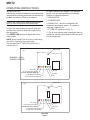
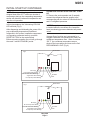
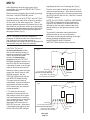
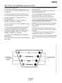
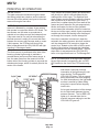
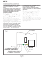
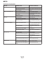
MDT2
INTRODUCTION
This manual provides the specifications and the
step-by-step procedures for the installation,
start-up, operation, maintenance and cleaning for
the SCOTSMAN MDT2 counter top cubelet ice
dispenser.
NOTE: To retain the safety and performance built
into this ice machine, it is important that installation
and maintenance be conducted in the manner
outlined in this manual.
Table of Contents
SPECIFICATIONS · · · · · · · · · · · · · · · · · · · · · · · · · · · · · · · · · · · · · · · · · · · · · Page 2
CABINET DIAGRAMS
· · · · · · · · · · · · · · · · · · · · · · · · · · · · · · · · · · · · · · · · · · Page 3
GENERAL INFORMATION AND INSTALLATION
· · · · · · · · · · · · · · · · · · · · · · · · · · · · Page 4
ELECTRICAL CONNECTIONS · · · · · · · · · · · · · · · · · · · · · · · · · · · · · · · · · · · · · · Page 5
WATER SUPPLY AND DRAIN CONNECTIONS · · · · · · · · · · · · · · · · · · · · · · · · · · · · · Page 6
FINAL CHECK LIST · · · · · · · · · · · · · · · · · · · · · · · · · · · · · · · · · · · · · · · · · · · · Page 7
OPERATING INSTRUCTIONS · · · · · · · · · · · · · · · · · · · · · · · · · · · · · · · · · · · · · · Page 8
INITIAL START UP CONTINUED · · · · · · · · · · · · · · · · · · · · · · · · · · · · · · · · · · · · · Page 9
SETTING THE DISPENSING SELECTOR · · · · · · · · · · · · · · · · · · · · · · · · · · · · · · · · Page 11
PRINCIPLE OF OPERATION · · · · · · · · · · · · · · · · · · · · · · · · · · · · · · · · · · · · · · · Page 12
REFRIGERANT CIRCUIT · · · · · · · · · · · · · · · · · · · · · · · · · · · · · · · · · · · · · · · · · Page 13
MECHANICAL SYSTEM · · · · · · · · · · · · · · · · · · · · · · · · · · · · · · · · · · · · · · · · · Page 14
COMPONENT DESCRIPTION · · · · · · · · · · · · · · · · · · · · · · · · · · · · · · · · · · · · · · Page 15
COMPONENT DESCRIPTION · · · · · · · · · · · · · · · · · · · · · · · · · · · · · · · · · · · · · · Page 16
COMPONENT DESCRIPTION · · · · · · · · · · · · · · · · · · · · · · · · · · · · · · · · · · · · · · Page 17
COMPONENT DESCRIPTION · · · · · · · · · · · · · · · · · · · · · · · · · · · · · · · · · · · · · · Page 18
SERVICE DIAGNOSIS · · · · · · · · · · · · · · · · · · · · · · · · · · · · · · · · · · · · · · · · · · Page 19
SERVICE DIAGNOSIS · · · · · · · · · · · · · · · · · · · · · · · · · · · · · · · · · · · · · · · · · · Page 20
MAINTENANCE AND CLEANING INSTRUCTION · · · · · · · · · · · · · · · · · · · · · · · · · · · · Page 21
CLEANING INSTRUCTIONS OF WATER SYSTEM · · · · · · · · · · · · · · · · · · · · · · · · · · · Page 22
REMOVAL AND REPLACEMENT
· · · · · · · · · · · · · · · · · · · · · · · · · · · · · · · · · · · · Page 23
TOP BEARING REPLACEMENT · · · · · · · · · · · · · · · · · · · · · · · · · · · · · · · · · · · · · Page 24
BEARING REPLACEMENT - CONTINUED · · · · · · · · · · · · · · · · · · · · · · · · · · · · · · · · Page 25
WATER SEAL · · · · · · · · · · · · · · · · · · · · · · · · · · · · · · · · · · · · · · · · · · · · · · · Page 26
May 2002
Page 1
MDT2
SPECIFICATIONS
MDT2C12:
Ice Maker Dispenser TouchFree 200 lb ice making capacity Cublet 12 lb storage
Important operating requirements:
MIN
MAX
- Air temperature
50°F
100°F
- Water temperature
40°F
95°F
- Water pressure
20 psi
70 psi
- Electrical voltage variations from
voltage rating specified on
nameplate
-10%
+10%
To keep your SCOTSMAN CUBELET DISPENSER
at peak performance levels, periodic maintenance
checks must be carried out as indicated in this
manual.
MACHINE SPECIFICATIONS
Model
Cond.
unit
Air
MDT2C12-1A
Basic
electrical
115/60/1
Cabinet Size
Finish
34 13/32” high x 15 9/32” wide x 26 7/64” deep
S. Steel
Amps
Watts
Amps fuse
6
550
15
Unit is equipped with leveling legs.
The unit has a power cord.
May 2002
Page 2
Comp.
HP
3/8
Ice bin
cap
12 lb.
MDT2
CABINET DIAGRAMS
May 2002
Page 3
MDT2
GENERAL INFORMATION AND INSTALLATION
UNPACKING AND INSPECTION
LOCATION AND LEVELING
1. Call your authorized SCOTSMAN Distributor or
Dealer for proper installation.
2. Visually inspect the exterior of the packing and
skid. Any severe damage noted should be reported
to the delivering carrier and a concealed damage
claim form filled in subject to inspection of the
contents with the carrier’s representative present.
3. a) Cut and remove the plastic strip securing the
carton box to the skid.
b) Cut open the top of the carton and remove the
polystyrene protection sheet.
c) Pull out the polystyrene posts from the corners
and then remove the carton.
4. Remove the top and sides panels of the unit and
inspect for any concealed damage. Notify carrier of
your claim for the concealed damage as stated in
step 2 above.
5. Remove all internal support packing and
masking tape.
6. Check that refrigerant lines do not rub against or
touch other lines or surfaces, and that the fan
blades move freely.
WARNING: This Ice Dispenser is designed for
indoor installation only. If the machine is operated
for extended periods at temperatures exceeding
the following limitations it will constitute misuse
under the terms of the SCOTSMAN Manufacturer’s
Limited Warranty resulting in LOSS of warranty
coverage.
Position the unit in the selected permanent
location. Criteria for selection of location include:
Min
Air Temperature
50°F
Water Temperature
40°F
Water pressure
20 psi
Voltage
-10%
(Compared to the nameplate)
Max
100°F
95°F
70 psi
+10%
Service access: adequate space must be left for all
service connections through the rear of the ice
machine.
7. Check that the compressor fits snugly onto all its
mounting pads.
This machine is air-cooled and sucks air through
the left side panel and blows air out the rear side of
the top panel. Do not install the machine where the
left and upper rear side airflows might be blocked.
8. Use clean damp cloth to wipe the surfaces
outside of the cabinet.
A minimum clearance of 6 inches is required at the
left and upper rear side for air circulation.
9. See data plate on the rear side of the unit and
check that local main voltage corresponds with the
voltage specified on it.
It is important that the machine be installed in a
location where it has enough space around it to be
accessible for service. Avoid hot, dirty and
crowded locations.
CAUTION: Incorrect voltage supplied to the ice
machine will void your parts replacement program.
NOTE: Do NOT place anything on top of the
machine. Leave the upper louvers open for
proper air exhaust.
10. Remove the manufacturer’s registration card
from the inside of the Users Manual and fill-in all
parts including Model and Serial Number taken
from the data plate. Forward the completed
self-addressed registration card to SCOTSMAN
factory.
The base of the MDT2 must be sealed to the
counter top.
1. Place the unit in its final position.
2. Place a bead of sealant on the counter top to
match the outside edge of the cabinet base and
sink.
Food grade silastic sealant such as Scotsman part
number 19-0529-01 is recommended.
May 2002
Page 4
MDT2
ELECTRICAL CONNECTIONS
See data plate for current requirements to
determine wire size to be used for electrical
connections. All SCOTSMAN ice machines require
a solid earth wire. This SCOTSMAN ice machine is
supplied from the factory completely pre-wired and
only needs to be plugged into a nearby 115 volt
outlet.
Make sure that the ice machine is connected to its
own circuit and individually fused (see data plate
for fuse size).
The maximum allowable voltage variation should
not exceed -10% and +10% of the data plate
rating. Low voltage can cause faulty functioning
and may be responsible for serious damage to the
overload switch and motor windings.
NOTE: All external wiring should conform to
national, state and local standards and regulations.
Check voltage on the line and the ice machine’s
data plate before connecting the unit.
May 2002
Page 5
MDT2
WATER SUPPLY AND DRAIN CONNECTIONS
GENERAL
WATER DRAIN
When choosing the water supply for the ice flaker,
consideration should be given to:
The recommended drain tube is a copper, rigid
plastic or reinforced flexible tubing (supplied) with
.75" (19mm) I.D. which runs to an open trapped
and vented drain. When the drain is a long run,
allow1/4" drop per foot.
a) Length of run
b) Water clarity and purity
c) Adequate water supply pressure
Note: Although soft, easily kinked vinyl tubing is
not recommended for a drain, a short length of ¾”
ID vinyl tubing is required to connect a rigid drain
tube to the 20 mm (25/32”) fitting on the back of
the MDT2.
Water is the most important single ingredient in
producing ice - these three items are very
important.
Low water pressure, below 20 psi may cause
malfunction of the ice machine unit.
Water containing excessive minerals will tend to
produce scale build-up on the interior parts of the
water system while water that’s too soft (water
contains too few mineral salts), will produce a very
hard flaked ice.
PLUMBING CONNECTIONS MUST CONFORM
TO ALL APPLICABLE CODES
CONNECT TO POTABLE WATER ONLY
The model MDT2 is capable of having water
connections through the bottom base or through
the rear bottom side of the machine. In this second
case it is necessary to remove the small panel at
the bottom rear.
Install a vertical open vent on the drain line high
point at the drain connection to ensure good
draining.
The ideal drain receptacle is a trapped and vented
floor drain.
NOTE: The water supply and the water drain
must be installed to conform with the local
code. In some case a licensed plumber and/or a
plumbing permit is required.
WATER SUPPLY
Connect to the 3/4" male water inlet fitting, using
the supplied fitting, to the cold water supply line. A
shut-off valve should be installed in an accessible
position between the water supply line and the unit.
If the water contains a high level of impurities,
consider installing a water filter or conditioner.
May 2002
Page 6
MDT2
FINAL CHECK LIST
1. Is the unit in a room where the ambient
temperatures are within a minimum of 50°F even in
winter months?
2. Is there at least a 6" clearance around the unit
for proper air circulation?
3. Is the unit level?
4. Have all the electrical and plumbing connections
been made, and is the water supply shut-off valve
open?
5. Has the voltage been tested and checked
against the data plate rating?
6. Has the water supply pressure been checked to
ensure a flowing water pressure of at least 20 psi.
7. Check all refrigerant lines and conduit lines to
guard against vibrations and possible failure.
8. Has the unit been sealed to the counter top?
9. Has the owner/user been given the Users
Manual and been instructed on the importance of
periodic maintenance checks?
10. Has the Manufacturer’s registration card been
filled in properly? Check the model and serial
number against the serial plate and mail the
registration card to Scotsman.
11. Has the owner been given the name and the
phone number of the authorized SCOTSMAN
Service Agency serving them?
May 2002
Page 7
MDT2
OPERATING INSTRUCTIONS
INITIAL START UP
After having correctly installed the ice machine and
completed the plumbing and electrical connections,
perform the following “Start-up” procedure.
B. After 3 minutes have elapsed – the stand by
period – the unit starts operating by activating
systems in following sequence:
1. GEAR MOTOR
2. COMPRESSOR
Remove the control board inspection panel and
cover to view the lights on the control board.
3. FAN MOTOR – which is controlled by the
condenser temperature sensor. The probe is
within the condenser fins.
A. Open the water supply line shutoff valve and
turn the main switch on the power supply line to
the ON position.
4. 2nd RED LED switches off (Fig. 2).
C. Two or three minutes after compressor start up;
cubelet ice should begin dropping off the ice spout
into the storage bin.
The GREEN LED will glow to signal that unit is
under power.
NOTE: Every time the unit is turned on after being
shut off for a period of time (electrically
disconnected) the 2nd RED LED will blink for 3
minutes (Fig.1).
Reset button
Fig 1
BLINKING – 3 MIN.
STAND-BY PERIOD
Bin empty
Bin full
Hi cond temp when Steady
3 minute wait when Blinking
No water
Auger Motor when Steady
Hi evap temp when Blinking
Power
Reset button
Fig 2
Bin empty
Bin full
Hi cond temp when Steady
3 minute wait when Blinking
No water
Auger Motor when Steady
Hi evap temp when Blinking
Power
May 2003
Page 8
MDT2
INITIAL START UP CONTINUED
NOTE: If the evaporating temperature has not
dropped lower than 30° F within ten minutes of
compressor start-up, the evaporating temperature
sensor will detect the abnormal temperature and
stop the unit operation.
In this circumstance, the 3rd warning YELLOW
LED will blink (Fig.3).
After diagnosing and eliminating the cause of the
poor evaporating temperature (insufficient
refrigerant in the system, inoperative compressor
or inoperative evaporator sensor), push the
RESET BUTTON on the control board.
Before resuming operation the unit will go through
the usual 3 minute STAND-BY period.
OPERATION CHECKS UPON THE UNIT START
UP
D. Remove the service panels and (if needed)
connect the refrigerant service gauges to the
corresponding service valves to check both the HI
and LO refrigerant pressures.
NOTE:The condenser temperature sensor, which
is located within the condenser fins, keeps the
head (condensing) pressure between two preset
valves.
If proper flow of cooling are is prevented by a
clogged condenser or inoperative fan motor, the
condenser temperature rises. When it reaches
158° F the condenser temperature sensor
shuts-off the ice machine and turns on the 2nd
RED WARNING LIGHT (Fig.4).
Reset button
Fig 3
Bin empty
Bin full
Hi cond temp when Steady
3 minute wait when Blinking
No water
Auger Motor when Steady
Hi evap temp when Blinking
Power
Reset button
Fig 4
Bin empty
Bin full
Hi cond temp when Steady
3 minute wait when Blinking
No water
Auger Motor when Steady
Hi evap temp when Blinking
Power
May 2003
Page 9
MDT2
signaling that there is a full storage bin (Fig.6).
After diagnosing and fixing the cause of the
temperature rise, push the RESET BUTTON on
the control board.
Before resuming operation the unit will go through
the usual 3 minute STAND-BY period.
E. Check for the correct CUT-OUT and CUT-IN of
the float reservoir water level sensors by shutting
off the valve on the water supply line. This will
cause a gradual decrease of the water level in the
float reservoir and as soon as the level gets below
the sensors, the flaker stops operating and the 5th
YELLOW WARNING LED will glow to signal the
shortage of water (Fig.5).
NOTE: The water level sensor detects the
presence of sufficient water in the float reservoir
and confirms it to the microprocessor by
maintaining a low voltage current flow between the
two sensors using the water as conductor.
CAUTION: The use of
de-mineralized water (water
with no salt content) having an
electrical conductivity lower than
30mS, will cause the water
sensors to stop working
properly which will CUT-OUT
the flaker operations and turn on
the YELLOW LED that indicates
a shortage of water, even though
water is indeed in the reservoir.
After this is done, open the water
supply line shutoff valve to refill
the float reservoir; the 5th
YELLOW LED goes off and the
2nd RED LED starts blinking.
The gear motor will start-up
immediately, 2 seconds later the
compressor will start and after
the 3 minutes the unit resumes
normal operation.
F. To check for the correct
operation of the electronic eye
that controls ice bin level, place
one hand between the sensing
“eye” (located in the ice spout) to
interrupt the light beam. This
interruption will cause the 1st
RED LED to go out. After about
6 seconds the unit shuts off and
the 6th YELLOW LED will light
Remove your hand to allow the electronic eye to
resume normal operation. After about 6 seconds
the flaker will resume the ice making process and
the YELLOW LED will turn off – after the 3 minute
STAND-BY period.
NOTE: The ICE LEVEL CONTROL (INFRARED
SYSTEM) is independent of the temperature.
However, the reliability of its detection can be
affected by dirt and scale sediment that may
deposit directly on the light source and on the
receiver.
To prevent ice machine malfunction due to
sediment build-up, be sure to follow the
instructions for the periodic cleaning of the light
sensor elements as detailed in the
MAINTENANCE AND CLEANING
INSTRUCTIONS section of this manual.
Reset button
Fig 5
Bin empty
Hi cond temp when Steady
3 minute wait when Blinking
Auger Motor when Steady
Hi evap temp when Blinking
Bin full
No water
Power
Reset button
Fig 6
Bin empty
Hi cond temp when Steady
3 minute wait when Blinking
Auger Motor when Steady
Hi evap temp when Blinking
May 2003
Page 10
Bin full
No water
Power
MDT2
SETTING THE DISPENSING SELECTOR
Setting the dispensing time
It’s possible to modify the dispensing time to 5, 10
or 15 seconds. To modify the original setting time
(5 seconds):
a) Push and hold the 4th switch (CONTINUOUS)
for 10 seconds until the first 3 lights start to blink,
b) Push & release the 1st switch (ICE) for a 5
second dispense.
a) First, select the Dispensing Mode by pushing
the proper switch.
b) Place a glass or a carafe in front of the two
Optical Dispensing Devices.
c) The dispensing drive motor and/or the water
solenoid valve starts. Ice and/or water is
discharged through the bottom plastic spout.
The drive motor and/or the water solenoid valve
remains in operation (per dispensing time settings)
unless the glass or carafe is removed.
nd
c) Push & release the 2 switch (ICE AND
WATER) for a 10 second dispense.
d) Push & release the 3rd switch (WATER) for a 15
second dispense.
The unit resumes a default dispense setting (Ice,
Ice and Water or Water) after each dispense.
To modify the resume mode (from factory set to
ICE) push the desired switch (ICE, ICE AND
WATER or WATER ) for 5 seconds.
Push the CONTINUOUS switch and check again
for the dispensing mechanism operation per the
steps above.
The drive motor and/or the water solenoid valve
will remain in operation until the glass or carafe is
removed.
I. If connected, remove the refrigerant service
gauges and re-attach the service panels.
H. CHECK OF THE DISPENSING OPERATING
MECHANISM
To check for the correct operation of the dispensing
mechanism:
J. Instruct the owner/user on the general operation
of the ice machine and its required cleaning and
care.
May 2002
Page 11
MDT2
PRINCIPLE OF OPERATION
WATER CIRCUIT
The water enters the machine through the water
inlet fitting (which has a strainer and is located at
the rear side of the cabinet) and goes to the water
reservoir through a float valve.
NOTE: The presence of the water in the float
reservoir is detected by a system of two sensors
that operate in conjunction with the PC Board. The
two sensors use the water as a conductor to
maintain a low voltage current flow between them.
If the water used is very soft (de-mineralized) or
the float reservoir is empty, the current that flows
between the sensors may become weak or cease.
If this happens, the PC Board will shut off the
flaker’s operation and the YELLOW LED will light
signaling a “Shortage of water.”
The float reservoir is positioned at the side of the
freezing cylinder high enough to maintain a
constant water level around the freezer auger. In
fact, the water flows from the reservoir into the
bottom inlet of the freezing cylinder to surround the
stainless steel auger, which is vertically fitted in the
center of the freezer.
In the freezer the incoming water gets chilled into
soft (slush) ice, which is moved upward by the
rotating action of the auger. The stainless steel
auger rotates counter-clockwise within the freezer
and is powered by a direct drive gear motor. It
carries the ice upward along the inner walls of the
freezer and as it raises the ice gets progressively
thicker and harder. As the ice rises upward it
moves toward the icebreaker (which is located on
the top end of the auger), where it gets compacted,
cracked and shifted horizontally to be discharged
out through the ice spout, into the storage bin.
Once the ice machine is turned on it starts the
automatic ice making process, which will continue
until ice storage bin is full enough to trigger the
control “eye” located on the sides of the ice spout.
As the ice level raises it interrupts the light beam
running between the two infrared lamps. The unit
stops after six seconds and the YELLOW LED
turns on to signal that there is a “Full Storage Bin”.
NOTE: The interruption of the light beam between
the two light sensors is signaled by the 1st RED
LED located on the front of the PC Board turning
off.
After about 6 seconds of steady
interruption of the light beam the unit
stops and the “Full Storage Bin”
YELLOW LED glows. The six second
delay prevents the unit from stopping
for small interruptions in the light beam
such as is caused by flakes sliding
along the ice spout before dropping
into the bin.
As ice gets scooped out of the storage
bin, the light beam between the two
sensors resumes. The 1st RED LED
lights up; 6 seconds later the ice
machine resumes making ice and the
YELLOW LED goes off.
May 2002
Page 12
MDT2
REFRIGERANT CIRCUIT
The hot gas refrigerant discharged from the
compressor reaches the condenser where it is
cooled down and condenses into liquid.
When the condenser temperature goes below the
pre-fixed limit, the temperature sensor changes its
electrical resistance again by reducing the flow of
current to the PC Board to cause a temporary stop
of the Fan Motor.
NOTE: If the condenser temperature probe senses
a rise in temperature to 158°F for one of the
following abnormal reasons:
· CLOGGED CONDENSER
· FAN MOTOR OUT OF OPERATION
· AMBIENT TEMPERATURE HIGHER THAN
Flowing into the liquid line it passes through the
drier filter, then it goes all the way through the
capillary tube where it loses some of its pressure.
At this time the pressure and temperature are
lowered and the refrigerant enters into the
evaporator coil wrapped around the freezer inner
tube.
The water being constantly fed into the freezer
inner tube exchanges heat with the refrigerant
circulating in the evaporator coil. This causes the
refrigerant to boil-off and it evaporates, thereby
changing from liquid into vapor.
The vapor refrigerant then passes through the
suction accumulator and the suction line where the
refrigerant exchanges heat with the one flowing
into the capillary tube (warmer) before being
sucked into the compressor to be re-circulated.
109.4°F
It will cause the total and immediate SHUT-OFF of
the machine in order to prevent the unit from
operating in abnormal and dangerous conditions.
When the probe stops the ice machine the 2nd RED
LED will turn on, warning the user of the Hi
Temperature situation. After eliminating the cause
of the increase in temperature, push the RESET
button (PC Board) to restart the ice machine. The
2nd RED LED starts blinking and three minutes
later the flaker unit resumes normal operation.
The refrigerant suction or Lo-pressure will be (in
normal ambient conditions about 70°F) about 14.5
PSIG within a few minutes from the unit’s start-up.
This value can vary by 1.5 to 2.9 psig in relation to
the water temperature variations influencing the
freezer cylinder.
NOTE: If no ice is made within ten minutes of unit
start up and the evaporating temperature detected
by the evaporator sensor is higher than 30° F the
ice machine stops and the 3rd WARNING
YELLOW LED blinks.
The refrigerant heat pressure is kept between two
pre-set values 131¸145 psig by the condenser
temperature sensor (the probe is located within the
condenser fins) in air-cooled versions.
When this condenser temperature sensor detects a
rise in condenser temperature (beyond the
pre-fixed limit) it changes its electrical resistance
and sends a low voltage power flow to the
microprocessor on the PC Board that energizes
(through a TRIAC) the Fan Motor in ON-OFF
mode.
May 2002
Page 13
MDT2
MECHANICAL SYSTEM
The mechanical system of the SCOTSMAN
Nugget Ice Dispenser consists of a gear motor
assembly that drives (through a ratchet coupling) a
worn shaft or auger placed on its vertical axis
within the freezing cylinder.
for the wrong rotation) and the 3rd YELLOW
WARNING LED turns on. This is done to avoid
overloading the electrical and mechanical
components of the entire Drive System and extend
their durability.
The gear motor is made of a single-phase electric
motor with a permanent capacitor. This motor is
directly fitted in the gear case through which it
drives – in a counter clockwise rotation at a speed
of 9.5 rpm – the freezer auger linked to it by the
ratchet coupling.
NOTE: After diagnosing and eliminating the source
of the gear motor slow rotation, restart the unit by
pushing the RESET button to or turning the power
line main switch OFF and ON.
NOTE If the gear motor rotates in the wrong
direction (counter-clockwise) or is not rotating at all
the unit will stop immediately and the 3RD
WARNING YELLOW LED will turn on showing the
intervention of the Electromagnetic Safety Device based on Hall Effect principle.
NOTE: Any time the machine stops with a problem
the front 4 LED’s start to blink.
REFRIGERANT METERING DEVICE:
· Capillary tube
OPERATING PRESSURES
(With 70°F ambient temperature)
After diagnosing and eliminating the source of the
failure, restart the unit by pressing the RESET
button or turn the power switch OFF and ON (Fig.
7).
· Discharge pressure: 130 to 145 psig
· Suction pressure: 14.5 psig
· REFRIGERANT CHARGE (R 134 A): 13 oz.
The RED LED will start blinking and after 3
minutes the ice machine will resume normal
operations by running first the gear motor and then
the compressor.
NOTE: Before charging the refrigerant system
always check the type of refrigerant and quantity
as specified on the individual ice machine data
plate.
When the gear motor rotating speed is slowed
below 1300 rpm - normal speed is 1400 rpm - the
Electromagnetic Safety Device transmits an
electrical signal to the MICROPROCESSOR to
stop the unit operation immediately (just as it does
The refrigerant charges indicated are relatives to
averages operating conditions.
Reset button
Fig 7
Bin empty
Bin full
Hi cond temp when Steady
3 minute wait when Blinking
No water
Auger Motor when Steady
Hi evap temp when Blinking
Power
May 2003
Page 14
MDT2
COMPONENT DESCRIPTION
A. EVAPORATOR TEMPERATURE SENSOR BLUE 2 POLE CONNECTOR - MANUAL RESET
The evaporator sensor probe is inserted into its
tube well, which is welded on the evaporator outlet
line. It detects the temperature of the refrigerant on
the way out of the evaporator and signals it by
supplying a low voltage current flow to the PC
Board microprocessor. According to the current
received, the microprocessor lets the ice machine
to continue its operations or not. If within 10
minutes of startup the evaporating temperature
does not go below 30°F the evaporator sensor
signals the microprocessor to stop the unit
operation immediately and causes the 3rd
WARNING YELLOW LED to blink.
B. WATER LEVEL SENSOR - RED TWO POLE
CONNECTOR – AUTOMATIC RESET
This sensor system consists of two small stainless
steel rods vertically fitted on the inner face of the
reservoir cover and electrically connected to the
low voltage circuit of the PC Board. When the
cover of the reservoir is positioned properly the tips
of both rods dip into the reservoir water and signal
its presence by supplying power to the PC Board.
NOTE: In the event of shortage of water in the
reservoir or if the water used is too soft
(de-mineralized) to cause greater resistance to the
current flow (conductivity lower than 30mS) this
sensor system causes the machine to shutoff to
protect it from running with an interrupted or
inadequate water supply.
If the temperature rises to 158°F or above the
current sent to the microprocessor causes the
machine to cease operation and turns on the 2nd
RED WARNING LED.
NOTE: After fixing the problem that caused the
high condenser temperature, press the RESET
button or turn the power line main disconnect
switch OFF and ON to restart the unit after the shut
down.
The fan motor will cycle on an off to maintain the
discharge pressure.
D. GEAR MOTOR ROTATION AND SPEED
SENSOR - RED FOUR POLE CONNECTOR MANUAL RESET
This safety device is housed on top of the Drive
Motor and detects - based on the Hall Effect
principle - the rotating speed and rotating direction
of the drive Motor. Should the rotating speed drop
below 1300 rpm the magnitude measured by this
device signals the microprocessor to stop the unit
and turns on the 3rd YELLOW LED. The same
reaction occurs when the drive motor rotates in the
wrong direction (counterclockwise) or it doesn’t
rotate at all.
NOTE: After diagnosing and eliminating the
problem that caused the intervention of the safety
device, press the RESET button or turn the power
line main disconnect switch OFF and ON to restart
the unit after the shut down.
When this happens the 5th YELLOW LED will turn
on warn that the ice machine is off and why.
C. CONDENSER TEMPERATURE SENSOR BLACK TWO POLE CONNECTOR –MANUAL
RESET
The condenser temperature sensor probe (located
within the condenser fins) detects condenser
temperature variations and signals them by
supplying current, at low voltage, to the PC
BOARD.
Current to the microprocessor on the PC Board
varies and as it does the microprocessor supplies,
through a TRIAC, power at a high voltage to the
fan motor so that it can cool the condenser and
reduce its temperature.
May 2002
Page 15
MDT2
COMPONENT DESCRIPTION
E. ICE BIN LEVEL LIGHT CONTROL – BLACK
FOUR POLE CONNECTOR –AUTOMATIC
RESET
F. ICE/WATER OPTICAL DISPENSING DEVICE BLUE FOUR-POLE CONNECTOR
The electronic ice bin level control (located on the
ice spout) stops the operation of the ice machine
when the light beam between the light source and
the sensor gets interrupted by the ice which
accumulates in the spout.
When the light beam is interrupted for 6 seconds,
the 1st RED LED (on the front of the PC board)
goes off and the ice machine stops ice production
and turns on the 6th YELLOW LED to show that
there is a full storage bin.
The 6-second delay prevents interruption of
machine operation in the case of minimal breaks in
the light beam that can occur due to the ice
dropping through the ice spout blocking the sensor.
Located on the front of the dispensing area it
consists of a combination of an infrared Transmitter
and Receiver.
When a glass or a carafe is placed in front of the
Infrared sources, the optical device transmits a
signal to the PC Board. This activates the
dispensing drive motor, which in turn, puts into
rotation a dispensing vane that pushes the ice
towards a rectangular opening located in the
bottom of the storage bin.
After the glass/carafe is removed or the dispensing
time has elapsed (5, 10 or 15 seconds according to
the setting) the infrared transmitter switches off the
dispensing drive motor.
As soon as ice is scooped out of the bin, the light
beam resumes contact with the two infrared
sensors of ice level control. The RED LED lights
up and after 6 seconds the ice machine resume its
operation and the 6th YELLOW LED turns off.
Reset button
Fig 6
Bin empty
Bin full
Hi cond temp when Steady
3 minute wait when Blinking
No water
Auger Motor when Steady
Hi evap temp when Blinking
Power
May 2002
Page 16
MDT2
COMPONENT DESCRIPTION
G. FRONT DISPENSING SELECTOR/DISPLAY BLACK SIX-POLE CONNECTOR
Placed in the upper front part of the dispensing
area it is used to select (varies by machine model):
a) Ice (first switch)
or
The PC BOARD is the brain of the system. It
relays through its microprocessor, the signals
received from the sensors to control the operation
of the different electrical components of the ice
machine (compressor, gear motor, etc.) as well as
the dispensing of the ice and water.
a) Ice (first switch)
The six LEDS on the front of the PC BOARD
indicate the following:
b) Ice and water (second switch)
RED LIGHT
c) Water - not chilled - (third switch)
- Empty storage bin
It is also possible to set up for “continuous”
dispensing operation just by pushing the fourth
switch before or after the selection of the
dispensed product.
RED LIGHT
Once completed the dispensing selector/display
resumes its original dispensing setting mode.
- Unit shut-off due to a Too high-condensing
temperature > 158°F
ON all the time
Blinking
NOTE: It is possible to modify the original resume
mode (default) by pushing the corresponding
switch for 5 seconds (all machines are factory set
to the ICE dispensing mode).
- 3 minutes start up delay time
YELLOW LIGHT
ON all the time
It is also possible to modify the dispensing time
controlled by the PC Board to 5, 10 or 15 seconds
by:
- Unit shut-off due to the wrong rotation direction of
gear motor
a) Push and hold the 4th switch “continuous” for
approximately 10 seconds till the first 3 lights start
to blink
- Unit shut-off due to the too lo speed of gear motor
b) Pushing the 1st switch (ICE) is equivalent to 5
seconds.
>-30°F after 10 min of operation
Pushing the 2nd switch (ICE+WATER) is
equivalent to 10 seconds.
GREEN LIGHT
Blinking
- Unit shut-off due to a Too high-evaporating temp.
Pushing the 3rd switch (WATER) is equivalent to
15 seconds.
- Unit under electrical power
H. PC BOARD (Data processor)
YELLOW LIGHT
The PC BOARD (in a plastic box on the right side
of the unit) consists of two separated printed circuit
boards; one at high voltage and the other at low
voltage, protected by three fuses, integrated with a
RESET button. It also consists of six aligned LEDS
monitoring machine operation, input terminals for
the leads of the sensor probes as well as input and
output terminals for the leads of the ice machine
electrical wires.
- Unit shut-off due to a too lo-water level into float
tank
YELLOW LIGHT
- Unit shut-off at full storage bin
BLINKING – 3 MINUTE STAND-BY PERIOD
May 2002
Page 17
MDT2
COMPONENT DESCRIPTION
I. FLOAT RESERVOIR
The float reservoir consists of a plastic water pan
which has a float valve with a set screw on it. The
float valve modulates the incoming water flow to
maintain a constant water level in the reservoir that
corresponds to the one in the freezing cylinder to
ensure proper ice formation and fluidity.
The drive motor rotor is kept aligned on its vertical
axis by two permanently lubricated ball bearings.
The gear case contains a train of three spur gears,
the first of which is fiber to limit the noise level. All
three gears are encased in case bearings and are
covered by lubricant grease (MOBILPLEX IP 44).
On the inside of the reservoir cover are two water
level sensors that detect the presence or shortage
of water in the reservoir.
Two seal rings, one fitted on the rotor shaft and the
other on the output shaft, keep the gear case
sealed. However, the interior can be inspected
and serviced by unbolting the two halves of the
aluminum gear case housing.
NOTE: It is very important to make sure that the
cover on the reservoir is seated properly to enable
the sensors to efficiently control the water level to
avoid undue shutoff.
The gear reducer output shaft is connected to the
freezer auger by a ratchet coupling which is made
of two toothed halves that engage only if turned in
the correct direction (counter-clockwise).
M. FAN MOTOR (Air cooled version)
J. FREEZING CYLINDER (EVAPORATOR)
The freezing cylinder is made of a stainless steel
vertical tube. The cooling coil is wrapped around
its exterior with the evaporating chamber. In its
interior is the auger which rotates on a vertical axis
that is kept aligned by the top and bottom bearings.
A water seal system is located in the bottom part of
the freezer and the ice breaker is fitted on top end.
The fan motor is controlled through the PC Board
and the TRIAC by the condenser temperature
sensor. Normally it operates to draw cooling air
through the condenser fins.
In a cold ambient situation, the fan motor can run
intermittently as the condenser pressure must be
kept between two corresponding head pressure
values.
The water constantly flows into the cylinder bottom
and it freezes into ice when it comes into contact
with the cylinder inner walls. The ice is then lifted
up by the rotating auger, compacted and forced out
by the icebreaker.
N. ICE DISPENSER DRIVE MOTOR
K. ICE BREAKER
By rotating, the dispensing vane pushes the ice
towards the bottom rectangular opening to force
the nugget ice to go through the bottom outlet
spout.
The icebreaker is made up of several rectangular
openings that the ice is forced to pass through. By
undergoing this process, the ice loses its excess of
water content and drops into the bin in hard dry
bits of ice.
The icebreaker houses the top bearing, which is
made of two roller bearings, positioned to
withstand the auger axial and radial loads. This
bearing is lubricated with a food-grade,
water-resistant grease.
Located on the upper side of the storage bin, it
turns the dispensing vane by a milled shaft inside
the round storage bin.
O. STORAGE BIN
The storage bin is located in the front of the ice
machine. It main purpose is to store the cubelet
ice produced by the evaporator until it reaches its
maximum level. In its bottom is placed the ice
spout as well as the water drain hole.
Inside the ice spout opening is the water outlet
tube connected to the solenoid valve.
NOTE: Check the conditions of both the lubricant
grease and the bearings every six months.
L. DRIVE GEAR MOTOR
P. DISPENSING WATER SOLENOID VALVE
Energized and controlled by the PC Board, it
allows a metered quantity of not chilled water to be
dispensed through the same opening of the ice.
This motor reducer is made of a single-phase
electric motor with a permanent capacitor directly
fitted on a gearbox.
May 2002
Page 18
MDT2
SERVICE DIAGNOSIS
SYMPTOM
POSSIBLE CAUSE
SUGGESTED CORRECTION
Unit will not run
Blown fuse in P.C. Board
Replace fuse & check for cause of blown
fuse
No LED lights
Master switch in OFF position
Turn switch to ON position
Inoperative P.C. Board
Replace P.C. Board
Loose electrical connections
Check wiring
6th Yellow LED glows
Inoperative or dirty ice level control
Replace or clean ice level control
5th Yellow LED glows
Shortage or too soft water
See remedies for shortage of water or
install a mineral salt metering device
2nd LED glows
High head pressure
Dirty condenser. Clean
3rd Yellow LED blinks
Too high evap. temperature
Inoperative fan motor. Replace
Check and charge refrigerant system
Shortage or lack of refrigerant
3rd Yellow LED glows
Gear motor tends to run on reverse
Check gear motor capacitor
Too low gear motor rotating speed
Check rotor bearings, freezer bearings and
interior of freezer for scores. Replace
whatever is worn or damaged.
No rotation of gear motor
Check for power to drive motor (16 A
fuses)
Check for stator winding
Gear motor starts and stops
Check for correct operation of drive after a
while motor magnetic sensor
Check for correct magnetic capacity of
magnetic cylinder
Compressor cycles intermittently
Low voltage
Check circuit for overloading
Check voltage at the supply to the
building. If low, contact the power
company
Low ice production
Will not dispense
Non-condensable gas in system
Purge the system
Compressor starting device with loose
wires
Check for loose wires in starting device
Capillary tube partially restricted
Blow charge, add new gas & drier, after
evacuating system with vacuum pump
Moisture in the system
Same as above
Low water level in the freezer
Adjust to approx 20mm below ice spout
Shortage of refrigerant
Check for leaks & recharge
Pitted or stained auger surface
Clean or replace auger
Dispense motor open
No power to dispense motor
Check windings
Check harness connections from
touch free sensors to control board &
from board to motor
Trace harness from touch free
sensors to PC board, jump the two
center pins, the dispense motor
should turn. If not replace the board
Check the harness for continuity, if
any wire is open, replace the harness
If the above does not prove to be a
problem, replace the sensors
Control board does not work
Open harness
Defective sensor
May 2002
Page 19
MDT2
SERVICE DIAGNOSIS
SYMPTOM
POSSIBLE CAUSE
SUGGESTED CORRECTION
Wet ice
Ambient temperature too high
Move unit to cooler location
High water level in the freezer
Lower to approx. 20mm below ice spout
Faulty compressor
Replace
Water not entering in the freezer
Air lock in feed line to freezer.
Machine runs but makes no ice
Clogged feed line to freezer. Clean it
Water leaks
Excessive noise or chattering
Gear motor noise
Gear stripped
Check and repair
Moisture in the system
Purge, replace drier and re-charge
Water seal leaking
Replace water seal
Water feed line to freezer leaking
Check and fasten hose clamp
Float valve not closing
Check and adjust float valve setting
screw
Mineral or scale deposit on auger
Remove and manually polish auger and
inner freezer walls and inner walls of
freezer barrel using emery paper
Low suction pressure
Add refrigerant to increase suction
pressure
Water feed line to freezer clogged
Vent and clean it
Low water level into freezer
Adjust to approx. 20 mm below ice
spout
Worn rotor bearings
Check and replace
Shortage or poor lubricant in gear case
Check for proper lubricant level by
opening gear case.
Top of gears must be covered with
lubricant
Shortage of water
Gear case bearings and gear racers worn
out
Check and replace worn parts
Strainer at water inlet fitting clogged
Remove strainer and clean
Float reservoir water nozzle clogged-up
nozzle
Remove float valve and clean
May 2002
Page 20
MDT2
MAINTENANCE AND CLEANING INSTRUCTION
A. GENERAL
The times and the procedures for maintenance and
cleaning are given as guides and are not to be
construed as absolute or invariable. Cleaning
especially will vary depending upon local water and
ambient conditions and the ice volume produced.
Each ice machine must be maintained individually,
in accordance with its particular location
requirements.
B. ice machine
The following maintenance should be scheduled at
least two times per year on these ice machines:
1. Check and clean the water line strainer or filter.
8. Check for water leaks and tighten drain line
connections. Pour water into the sink to be sure
that drain line is open and clear.
9. Check the ice level control sensor to test
shut-off. Put your hand between the light source
and the receiver on the upper side of the storage
bin to cut off the light beam for at least 6 seconds.
This should cause the 1st RED LED on the front of
the PC board to turn off and, 6 seconds later the
ice machine will cease operation and the 6th
YELLOW LED will turn on. Once you remove your
hand the ice machine should resume normal
operation within a few seconds.
2. Remove the cover from the float reservoir – be
careful to not damage the two water sensors –and
depress the float to make sure that a full stream of
water enters the reservoir.
NOTE: The ice level control uses a device that
senses light, therefore they must be kept clean
enough so they can “see”.
3. Check that the ice machine is level.
Every month clean/wipe the sensing “eyes” with a
clean soft cloth.
4. Check that the water level in the water reservoir
is below the overflow but high enough that it does
not run out of the spout opening.
NOTE: The float must stop the incoming water flow
when the rubber housed in the setting screw is
perpendicular to the water nozzle.
5. Clean the water system, water reservoir and the
interior of freezing cylinder using a solution of
SCOTSMAN Ice Machine Cleaner. Refer to
section C. CLEANING INSTRUCTIONS OF
WATER SYSTEM for cleaning procedures and
after cleaning will indicate frequency and
procedure to be followed in local areas.
NOTE: Cleaning requirements vary according to
the local water conditions and individual user
operation.
6. If required, polish the two sensor rods secured
to the float reservoir cover. Heavy scale sediment
on them can be removed with the help of a bit of
SCOTSMAN Cleaner plain.
10. Check for refrigerant leaks and for proper frost
line, approx. 8 inches from the compressor.
When in doubt of refrigerant charge, connect
refrigerant gauges to corresponding Schräder
valves and check for correct refrigerant pressures.
(See Operating Pressure on page 19 of this
manual).
11. Check that fan blades move freely and are not
touching any surfaces.
12. Remove the ice spout cover, loosen the bolt
securing the casting ice sweep and remove it; then
inspect the top bearing. Wipe away existing
grease and apply a coating of food grade
waterproof grease (P/N F263612-00).
NOTE: Use of food-grade, waterproof grease to
lubricate the top bearing is recommended.
13. Turn the ice-dispensing spout and remove it.
Wash and sanitize it.
14. Remove the sink grill for washing and
sanitizing.
7. With the ice machine and fan motor OFF clean
condenser using vacuum cleaner, whiskbroom or
non-metallic brush taking care to do not damage
the condenser temperature sensor.
May 2002
Page 21
MDT2
CLEANING INSTRUCTIONS OF WATER SYSTEM
1. Switch OFF the power supply to the MDT2.
2. Remove the top panel and the top cover of the
storage bin with the dispensing drive motor.
If this should occur it is recommended that you
stop the ice machine for few minutes in order to
allow the ice in the freezer to partially melt.
4. Close the water shutoff valve on water line.
12. When all of the cleaning solution has been
used up, open the water shutoff valve to allow new
fresh water to flow into the reservoir. Let the unit
continue to run until the ice resumes the normal
color and hardness.
5. Remove the left side panel to gain access to the
water reservoir.
13. Stop the ice machine and pour warm water on
the ice deposited into the storage bin to melt it.
6. Remove the float reservoir cover and jump the
two water level sensors with a piece of copper
wire.
NOTE: DO NOT use ice produced with the
cleaning solution. Be sure none remains in the bin.
3. Remove all ice stored in the bin to prevent it
from getting contaminated with the cleaning
solution.
7. Remove the right service panel and loosen the
drain plug from the water purge tube to drain all of
water our of the freezer. Then re-plug the purge
tube.
CLEANING
8. Prepare the cleaning solution by diluting it in a
plastic container with 2.1 quarts (2 liters) of warm
water (113°-122°F) with 7 ounces (0.2 liters) of
SCOTSMAN Ice Machine Cleaner.
WARNING: SCOTSMAN Ice Machine Cleaner
contains Phosphoric and Hydroxyacetic acids.
These compounds are corrosive and may cause
burns if swallowed, DO NOT induce vomiting. Give
large amounts of water or milk and call a Physician
immediately. In case of external contact, flush with
water. KEEP OUT OF THE REACH OF CHILDREN
SANITATION
14. Pour into the water reservoir locally approved
sanitizer mixed according to the directions for that
sanitizer. A possible saniziter can be obtained by
mixing 1 ounce of liquid household bleach with 2
gallons of warm water.
15. Leave the unit running for approx 10 minutes
then remove the copper wire used to jump the two
sensors for the water level and place the cover
back on the float reservoir.
NOTE: DO NOT use ice produced with the
sanitizing solution.
16. With a sponge moistened with a sanitizing
solution, wipe clean all bin interior surfaces.
REMEMBER: To prevent the accumulation of
undesirable bacteria it is necessary to sanitize the
interior of the storage bin with an anti-algae
disinfectant solution every week.
9. Pour the cleaning solution into the water
reservoir until it reaches the proper level.
10. After 15 minutes switch ON the Master switch
to start the unit.
11. Wait till the machine starts to discharge ice,
then continue to slowly pour the cleaning solution
into the water reservoir taking care to maintain the
level just below the overflow.
NOTE: The ice made with the cleaning solution is
slushy and colored. It may also loose fluidity
creating some resistance in being elevated and
extruded; this situation can be heard by the
creaking noise made by the ice.
May 2002
Page 22
MDT2
REMOVAL AND REPLACEMENT
Bearings, Auger, Water Seal
To remove gear reducer.
Note: Metric tools are required for this procedure.
Disconnect electrical power.
1. Disconnect power leads and sensor wires from
motor.
1. Remove all panels and the sink assembly.
2. Perform steps to remove bottom bearing.
2. Remove the spout cover.
3. Use a 10 mm socket or box wrench to remove
the 5 bolts holding the gear reducer to the unit.
3. Use a 17mm socket to remove the top bolt
holding the ice sweep to the auger.
4. Remove the gear reducer from the unit.
Reverse all individual sections to reassemble
that section except for the top bearing and
water seal. See the next page.
4. Use a 13mm socket to remove the four bolts
holding the breaker to the auger.
5. Lift up to remove breaker.
To remove top bearing:
6. Remove snap ring from the top of the breaker.
7. Turn breaker over and using a ¾” punch or bolt,
tap the bearing out from the bottom.
To remove auger:
8. After removing breaker, pull up on the auger to
remove it.
To remove water seal or bottom bearing.
9. Remove bin cover.
10. Disconnect drain and water line from bin.
11. Remove nut holding bin to chassis.
12. Pull bin out of machine.
13. Remove screws holding air deflector to chassis
and pull deflector out of the unit.
14. Remove screws holding reservoir to bulkhead
panel.
15. Remove screws holding bulkhead panel to
chassis frame, push panel back several inches.
16. Use a 13 mm open end or box wrench and
remove the three bolts holding the adapter stand to
the evaporator.
17. Lift evaporator up and off the stand.
18. Tap water seal and bottom bearing out of the
evaporator from the top down.
May 2002
Page 23
MDT2
TOP BEARING REPLACEMENT
Replacement of the top bearing
3. The bearing’s inner race must be supported
during installation. Make an insertion tool. Use a
5/16 - 18 x 3” bolt, a ¾” copper coupling, two or
three washers (one must be less than ¾” OD to go
inside the breaker) and two nuts to hold it together:
The MDT2 top bearing is a unique design. It is
two bearings in one: a flat thrust bearing and a
roller bearing.
The bearing will separate if not installed
properly. Do not attempt to install it unless it is
secured as described in these instructions.
5/16” bolt
¾” copper
coupling
1. Carefully clean out the breaker, removing any
debris or dirt. If using a new breaker, skip this step.
2. Separate the flat-bearing & thrust washer from
the new roller bearing.
Flat Washer
Flat bearing
Thrust Washer
Not Shown
Roller
Bearing
Large Flat
Washer
Nut for
centering
Roller Bearing
Nut for
tightening
Flat
washer
Construction of Bearing Insertion Tool
· Place copper coupling onto top of bearing
· Place large washers over coupling and small
washer under bottom of bearing.
· Insert bolt through large washers, coupling and
bearing. Run one nut into bearing to center the
bolt. Add small washer and nuit. Tighten nut
finger tight.
May 2002
Page 24
MDT2
BEARING REPLACEMENT - CONTINUED
6. Remove coupling, bolt, washers and nuts.
7. The roller bearing is fully seated when it is
13/16” from the top edge of the breaker.
8. Thoroughly lubricate the thrust bearing and
place it on top of the roller bearing. The inner race
of the roller bearing must project through the
center of the flat thrust bearing.
9. Install the flat washer (provided with the new
bearing) on top of the flat thrust bearing.
Tighten finger tight
before inserting into
breaker
10. Return the snap ring to its normal position.
11. Add food grade water resistant grease to the
top of the bearing area.
12. Assemble onto auger and secure with the
original bolt.
Bearing and Tool
4. Add food grade lube to the edges of the breaker
where the bearing will be inserted.
5. Tap the new roller bearing into the breaker using
a plastic mallet.
Tap Bearing & Tool into Breaker
May 2002
Page 25
MDT2
WATER SEAL
Stationary Half
1. Insert new water seal into bottom of evaporator.
2. Insert new bearing under the water seal, push or
tap both in until the bottom of the bearing is flush
3. Assemble adapter to evaporator. Tightening the
mounting bolts will correctly position the bottom
bearing and bottom seal.
Rotating Half
1. Remove old rotating half from the auger. Clean
the mounting area.
2. Place a bead of food grade sealant (such as
Scotsman part number 19-0529-01) onto the
shoulder of the auger where the rotating half of the
water seal will be installed.
3. Wash the new seal in water. While wet, slip it
onto the bottom of the auger, rubber side toward
the auger. Push up until seated against the
sealant. Do not allow any sealant to come into
contact with the face of the seal.
Bottom of
Auger
May 2002
Page 26