1
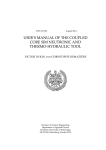
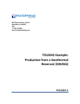
B
ELECTRIC SYSTEM
TROUBLESHOOTING
XTM - XSM
WORKSHOP MANUALS
B - TROUBLESHOOTING
ELECTRIC SYSTEM TROUBLESHOOTING
Introduction
B
CHAPTER
B
ELECTRICAL SYSTEM TROUBLESHOOTING
12.03
ISSUE
PAGE
SECTION 1
ENGLISH
INTRODUCTION ............................................................................................................................................... 4
Manual updates ........................................................................................................................................ 4
Notes for easy consultation ...................................................................................................................... 4
Page layout ...................................................................................................................................... 4
Modified pages ................................................................................................................................. 5
Additional pages ............................................................................................................................... 5
Editing symbols ................................................................................................................................ 5
Abbreviations .................................................................................................................................... 7
TROUBLESHOOTING ...................................................................................................................................... 8
Wiring diagram ......................................................................................................................................... 8
Connection of the switches described in this manual ..................................................................... 9
Ignition system circuit .............................................................................................................................10
Ignition system troubleshooting ....................................................................................................... 11
Charging system circuit ........................................................................................................................... 12
Charging system troubleshooting .....................................................................................................13
Light system circuit ................................................................................................................................. 14
Light system troubleshooting ...........................................................................................................15
Signalling system circuit ......................................................................................................................... 20
Turn indicator troubleshooting .......................................................................................................... 21
Stop light troubleshooting ................................................................................................................ 23
Horn troubleshooting ........................................................................................................................ 24
Water temperature probe troubleshooting ...................................................................................... 25
Mixture oil indicator light troubleshooting ....................................................................................... 25
fuel reserve indicator light troubleshooting ........................................................................................ 26
Neutral indicator light troubleshooting .............................................................................................. 26
Speedometer sensor troubleshooting ...............................................................................................26
MODE button troubleshooting ........................................................................................................ 26
Revolution counter troubleshooting ..................................................................................................27
Configuration of the digital instrument connector ......................................................................................27
Electrical component layout ....................................................................................................................28
3
B - TROUBLESHOOTING
B
ELECTRIC SYSTEM TROUBLESHOOTING
Introduction
CHAPTER
• Malaguti reserves the right to make any and all changes to its vehicles as it deems fit and appropriate at any
time without prior notice.
• No part of this publication, whether text or illustrations, may be reproduced or circulated. Malaguti reserves all rights over this publication. Reasons must be given for any request for permission (written) thereto.
FIRST EDITION: 05/03
INTRODUCTION
• This publication describes all necessary steps for troubleshooting concerning the electrical system (of the
models indicated on the front page) and of the possible service operations, which are necessary for their solution.
It supplies the trade technicians (authorised customer service centres) with the necessary information for
operating in compliance with the modern concepts of “good practice” and “safety at work”.
ENGLISH
• Further information can be derived from the “Chassis” workshop manual - from the “Engine” workshop
manual - from the Spare Parts catalogue.
• All described operations must be performed by technicians with the necessary skill and experience.
• The steps for the removal of body parts and of electrical and mechanical components, to allow access to wiring
or electric components to service, can be taken from the Chassis Workshop Manual.
• We recommend you follow the information given in this publication with care.
• For any further information you may need, refer to the Malaguti S.p.A. Technical Department.
MANUAL UPDATES
• Updated pages of this publication will be delivered by us (in a reasonable time) already punched and therefore
ready to be incorporated in the Manual. The superseded sheets should not be removed from the manual as they
remain applicable to the servicing of pre-modified models.
• The table of contents will be duly updated in the event that new pages are inserted, which render the consultation of the manual difficult.
• IMPORTANT! The Electrical System Troubleshooting Manual is to be considered as an essential tool to be
properly kept up-to-date so as to maintain its “validity” over time.
NOTES FOR EASY CONSULTATION
PAGE LAYOUT
4
Y
Chapter
X
Section title
W
Page N°
Z
Date of issue
PAGE
SECTION 1
ISSUE
05.03
B - TROUBLESHOOTING
ELECTRIC SYSTEM TROUBLESHOOTING
Introduction
Z
B
Y
ENGLISH
X
CHAPTER
W
MODIFIED PAGES
• Modified pages shall bear the same number as those in the previous edition /pre-modified ones,
followed by the letter M, with the date of issue appearing in the appropriate box.
• Modified pages may contain new illustrations; in this case, the added illustration (or illustrations) will bear the
number of the illustration on the former page, followed by a letter.
ADDITIONAL PAGES
• Any additional pages shall bear the last number of the section to which they belong, followed by the letter A and
the date of issue.
EDITING SYMBOLS
• Symbols have been provided for quick and easy reference (see page 6), identifying situations requiring utmost
attention or providing practical suggestions or simple information.
• These symbols may appear next to a text (in which case they refer solely to the text itself), next to a figure
(in which case they refer to the topic illustrated in the figure and to the relative text), or at the top of the page
(in which case they refer to all the topics dealt with in the page).
Note:
The meaning of the symbols should be duly memorised as their scope is to avoid having to repeat basic technical
concepts or safety recommendations. They are therefore to be considered as veritable “memory tags”. In case
of any doubt as to their meaning, consult the page in which they are fully described.
05.03
ISSUE
PAGE
SECTION 1
5
B - TROUBLESHOOTING
ELECTRIC SYSTEM TROUBLESHOOTING
B
CHAPTER
A)
Introduction
CAUTION! Recommendations and precautions regarding rider
safety and motor vehicle integrity.
A
B)
C)
WARNING!
Situations entailing the risk of personal injury to maintenance or
repair mechanics, other workshop personnel or third parties, or
damage to environment, vehicle or equipment.
B
FIRE HAZARD
Indicates operations which may constitute a fire hazard.
C
ENGLISH
D)
RISK OF EXPLOSION
Indicates operations which may constitute a risk of explosion.
D
E)
F)
TOXIC FUMES
Indicates a possibility of intoxication or inflammation of the upper
respiratory tract.
E
MECHANICAL MAINTENANCE
Operations to be performed only by an expert mechanic.
F
G)
H)
ELECTRICAL MAINTENANCE
Operations be performed only by an expert electrical/electronic
technician
G
NO! Operations to be absolutely avoided
H
I)
ENGINE SERVICE MANUAL
Indicates information which may be obtained by referring to said
manual.
I
M
L)
6
SPARE PARTS CATALOGUE
Indicates information which may be obtained by referring to said
catalogue
PAGE
SECTION 1
L
R
ISSUE
05.03
B - TROUBLESHOOTING
ELECTRIC SYSTEM TROUBLESHOOTING
Introduction
CHAPTER
B
ABBREVIATIONS
F
Cs
P
Pr
S
Sc
T
V
Figure
Tightening torque
Page
Paragraph
Section
Diagram
Table
Screw
ENGLISH
Note:
The letter V in the illustrations refers to retaining or adjusting screws. The number following this letter refers to the
number of the same type of screw in the unit or component described and illustrated. Letters not followed by a
number indicate a single screw. In case of different screws being referred to in the illustration, the letter V is
followed by a number and a small letter, for instance: (V4a).
Unless otherwise specified, units and components are reassembled by proceeding in the reverse order of removal.
Before any servicing, make sure that the motorbike is perfectly stable.
The front wheel should preferably be anchored to the equipment (A - F 4) integral with the lifting board.
A
F4
05.03
ISSUE
PAGE
SECTION 1
7
B - TROUBLESHOOTING
B
ELECTRIC SYSTEM TROUBLESHOOTING
CHAPTER
Troubleshooting
WIRING DIAGRAM
ENGLISH
8
PAGE
SECTION 2
ISSUE
SECTION 2
02.04
B - TROUBLESHOOTING
ELECTRIC SYSTEM TROUBLESHOOTING
Troubleshooting
CHAPTER
B
CONNECTION OF THE SWITCHES DESCRIBED IN THIS MANUAL
AR
B -MA
RH CONTROL
This manual contains connection diagrams, like the one illustrated hereby, which
illustrate how switch terminals should be connected (key switch, brake switch,
MODE button, etc.).
OFF
ON
The first column from the left indicates the different positions of the switch, the top
line the colour of the wires connected to the switch terminals.
MODE
The symbol “
” identifies terminals in which there is a condition of continuity,
i.e. a closed circuit, in a certain position of the switch.
ENGLISH
In this diagram:
“B-MA and AR”: there is continuous contact when the switch is “ON”.
05.03
ISSUE
PAGE
SECTION 2
SECTION 2
9
B - TROUBLESHOOTING
B
ELECTRIC SYSTEM TROUBLESHOOTING
CHAPTER
Troubleshooting
IGNITION SYSTEM CIRCUIT
ENGLISH
10
PAGE
SECTION 2
ISSUE
SECTION 2
02.04
B - TROUBLESHOOTING
ELECTRIC SYSTEM TROUBLESHOOTING
Troubleshooting
CHAPTER
B
A) Check resistance of the spark plug cap
- Detach the spark plug cap from the H.V. cable and
connect the tester (kΩ) as follows (F1):
- Tester (+) terminal
side 1
- Tester (-) terminal
side 2
- Spark plug cap resistance: 5 kΩ (20°C)
- Not compliant: replace the spark plug cap
F1
B) Check resistance of the electronic control unit
- Connect the tester (kΩ) to the control unit as follows (F2):
- Tester (+) terminal
H.V. cable
- Tester (-) terminal
lead terminal (green
cable)
- Secondary winding resistance: 5-6 kΩ (20°C)
- Not compliant: replace the control unit
F2
ENGLISH
IGNITION SYSTEM TROUBLESHOOTING
FLYWHEEL
C) Check resistance of power supply cable (green cable)
- Connect the tester (Ω) to the flywheel as follows (F3):
- Tester (+) terminal
green cable
- Tester (-) terminal
white cable
- Power supply resistance: 640-780 Ω (20°C)
- Not compliant: replace the flywheel magneto
MAGNETO
F3
D) Check pick-up resistance (red cable)
- Connect the tester (Ω) to the flywheel as follows (F4):
- Tester (+) terminal
red cable
- Tester (-) terminal
white cable
- Pick-up resistance: 100-140 Ω (20°C)
- Not compliant: replace the flywheel magneto
FLYWHEEL
MAGNETO
F4
E) Check key switch
- Disconnect the connector and connect the tester (Ω):
1) - Tester (+) terminal
KEY OFF
KEY ON
KEY ON
-1ST CLICK
2ND CLICK
red/white cable
CONTINUITY
DISCONTINUITY
DISCONTINUITY
Up to chassis n° 7086713
2) - Tester (+) terminal
KEY OFF
KEY ON
KEY ON
-1ST CLICK
2ND CLICK
orange cable
DISCONTINUITY
CONTINUITY
DISCONTINUITY
Up to chassis n° 7086713
3) - Tester (+) terminal
KEY OFF
KEY ON
KEY ON
-1ST CLICK
2ND CLICK
Up to chassis n° 7086713
yellow cable
DISCONTINUITY
CONTINUITY
CONTINUITY
- Tester (-) terminal
KEY OFF
KEY ON
blue cable
CONTINUITY
DISCONTINUITY
From chassis n° 7086714
- Tester (-) terminal
KEY OFF
KEY ON
green cable
DISCONTINUITY
CONTINUITY
From chassis n° 7086714
- Tester (-) terminal
KEY OFF
KEY ON
green/black cable
DISCONTINUITY
CONTINUITY
From chassis n° 7086714
WARNING: if the white/black cable leading from the switch is grounded, the motor does not start.
02.04
ISSUE
PAGE
SECTION 2
SECTION 2
11
B - TROUBLESHOOTING
B
ELECTRIC SYSTEM TROUBLESHOOTING
CHAPTER
Troubleshooting
CHARGING SYSTEM CIRCUIT
ENGLISH
12
PAGE
SECTION 2
ISSUE
SECTION 2
02.04
B - TROUBLESHOOTING
ELECTRIC SYSTEM TROUBLESHOOTING
Troubleshooting
CHAPTER
B
CHARGING SYSTEM TROUBLESHOOTING
If the battery is still flat, after it has been replaced or recharged, proceed as follows:
A) Check charging voltage
-
Connect the tester (20 V DC) to the battery as in (F5):
Tester (+) terminal
+ battery pole
Tester (-) terminal
- battery pole
Start the engine at approx. 7000 RPM
Voltage measured 13.5-14V
Not compliant: continue searching
F5
ENGLISH
B) Check the flywheel magneto charging coil
FLYWHEEL
- Disconnect the connectors from the flywheel magneto
and connect the tester (Ω) as follows (F6):
- Tester (+) terminal
yellow cable
- Tester (-) terminal
white cable
- Charging coil resistance: 0.2-0.4Ω (20°C)
- Not compliant: replace the flywheel
- Compliant: continue searching
F6
C) Check that the cables have been connected to the regulator connector in the right sequence (see
wiring diagram).
D) Check continuity (tester Ω) of the yellow/purple cable leading from the flywheel to the regulator.
E) Check continuity of the yellow cable (tester Ω) leading from the regulator to the battery (pole +).
F) Check continuity (tester Ω) of the black grounding cable connected to the regulator connector.
G) Check the rectifier diode (F7)
The diode is under the seat, connected to the yellow cable
leading to the (+) pole of the battery.
- Remove the diode and connect the tester (
follows:
- Tester (+) terminal
terminal 1
- Tester (-) terminal
terminal 2
- The value measured must be (
435)
- Not compliant: replace the diode
) as
F7
WARNING:
to avoid troublesome inconveniences on electrical components, make sure the diode is
fitted before connecting the battery.
H) If all checks have positive results, replace the regulator.
05.03
ISSUE
PAGE
SECTION 2
SECTION 2
13
B - TROUBLESHOOTING
B
ELECTRIC SYSTEM TROUBLESHOOTING
CHAPTER
Troubleshooting
LIGHT SYSTEM CIRCUIT
ENGLISH
14
PAGE
SECTION 2
ISSUE
SECTION 2
02.04
B - TROUBLESHOOTING
ELECTRIC SYSTEM TROUBLESHOOTING
Troubleshooting
CHAPTER
B
LIGHT SYSTEM TROUBLESHOOTING
WARNING: the vehicle’s lights come on when the key is in its “ON” position.
If the lights do not work, proceed as follows:
A) Check the light coil resistance (F8)
FLYWHEEL
- Disconnect the flywheel connector and connect the
tester (Ω):
Tester (+) terminal
yellow cable
Tester (-) terminal
white cable
Light coil resistance: 0.2_0.4Ω (20°C)
Not compliant: replace the flywheel
Compliant: continue searching
ENGLISH
-
F8
B) Make sure that the cables of the regulator connector are correctly positioned and firmly secured in
place (see wiring diagram).
C) Check continuity (tester Ω) between the yellow cable leading from the flywheel and the purple/
yellow cable leading to the regulator.
D) Check ground continuity (tester Ω) between the black cable in the regulator and a grounded point of
the frame (to be tested after disconnecting the regulator terminal board).
E) Check the voltage regulator (F9)
- Connect the tester (AC) to the regulator connector
(leaving the latter plugged in)
- Tester (+) terminal
purple/yellow cable
- Tester (-) terminal
black cable
- Start the engine at 7000 RPM
- The voltage measured should be: 12 volts
- Not compliant: replace the regulator
- Compliant: continue searching
F9
F) Check continuity (tester Ω) of the yellow cable leading from the regulator to the key switch.
G) Check the key switch (see page 11).
(SWITZERLAND version only)
Check continuity (tester Ω) of the pink cable leading from the key switch to the left hand switch. If
there is no continuity, replace the left hand switch.
02.04
ISSUE
PAGE
SECTION 2
SECTION 2
15
B - TROUBLESHOOTING
B
ELECTRIC SYSTEM TROUBLESHOOTING
CHAPTER
Troubleshooting
If the headlights are not working, proceed as follows:
A) Check continuity of the lamp and lamp socket
- Discontinuity: replace the lamp and/or lamp socket
- Continuity: continue searching
ENGLISH
B) Check voltage delivered to the front lamp socket
- Connect the tester (20V AC) to the lamp socket
- Tester (+) terminal
pink cable
- Tester (-) terminal
black cable
- Turn the key to “ON”.
- Start the engine at 7000 RPM
- The voltage measured should be: 12 volts
- Not compliant: continue searching.
C) Check continuity of the pink cable
Ω) to the pink cable leading from the key switch to the headlight connector.
- Connect the tester (Ω
- No continuity: the pink cable is interrupted. Repair (see wiring diagram).
- Continuity: black cable interrupted. Repair by providing a jumper between the black cable connected to the
headlight and a grounded point of the frame.
(SWITZERLAND version only - If the front parking light does not work)
Check continuity of the pink cable
Ω) to the pink cable leading from the key switch to the parking light lamp socket.
- Connect the tester (Ω
- No continuity: the pink cable is interrupted. Repair (see wiring diagram)
- Continuity: black cable interrupted. Repair by providing a jumper between the black cable connected to the
parking light lamp socket and a grounded point of the frame.
If the low beam is not working, proceed as follows:
A) (SWITZERLAND version only)
Check continuity of the lamp
- Discontinuity: replace the lamp.
B) (SWITZERLAND version only)
Check left hand switch.
Ω) to the switch as follows:
Connect the tester (Ω
- Tester (+) terminal
white/blue cable
- Tester (-) terminal
pink cable
- Turn the switch light to the “LO” symbol.
- No continuity: replace the left hand switch.
- Continuity: the white/blue cable leading from the left hand switch to the lamp socket is interrupted. Repair
(see wiring diagram)
16
PAGE
SECTION 2
ISSUE
SECTION 2
02.04
B - TROUBLESHOOTING
ELECTRIC SYSTEM TROUBLESHOOTING
Troubleshooting
CHAPTER
B
If the low beam light is not working but the low beam indicator light is, proceed as follows:
A) (SWITZERLAND version only)
Check continuity of the lamp
- Discontinuity: replace the lamp.
B) (SWITZERLAND version only)
Check continuity of the blue cable leading from the left hand switch to the lamp socket.
- No continuity: repair the blue cable (see wiring diagram).
ENGLISH
If the low beam light and indicator light are not working, proceed as follows:
A) (SWITZERLAND version only)
Check left hand switch.
Ω) to the switch as follows:
Connect the tester (Ω
- Tester (+) terminal
blue cable
- Tester (-) terminal
pink cable
- Turn the light switch to the “HI” symbol.
- No continuity: replace the left hand switch.
If the low beam indicator light is not working, proceed as follows:
A) (SWITZERLAND version only)
Check continuity of the light bulb
- Discontinuity: replace the light bulb.
B) (SWITZERLAND version only)
Check continuity of the blue cable leading from the left hand switch to the lamp socket of the instrument board indicator light.
- No continuity: the blue cable is interrupted. Repair (see wiring diagram)
- Continuity: there is no grounding point. Repair by providing a jumper between the black cable connected to
the lamp socket and a grounded point of the frame.
02.04
ISSUE
PAGE
SECTION 2
SECTION 2
17
B - TROUBLESHOOTING
B
ELECTRIC SYSTEM TROUBLESHOOTING
CHAPTER
Troubleshooting
If the tail light does not work, proceed as follows:
A) Check continuity of the lamp
- Discontinuity: replace the lamp
B) Check the voltage delivered to the rear lamp socket
ENGLISH
-
Connect the tester (AC 20V) to the lamp socket (F10)
Tester (+) terminal
pink cable
Tester (-) terminal
black cable
Turn the key to “ON”.
Start the engine at 7000 RPM
The voltage measured should be: 12 volts
Not compliant: continue searching
F10
C) Check continuity of the pink cable
-
Ω) as follows (F11):
Connect the tester (Ω
Tester (+) terminal
terminal 1
Tester (-) terminal
terminal 2
No continuity: the pink cable leading from the key switch
to the tail light is interrupted. Repair (see wiring diagram).
PARKING LIGHTS
STOP LIGHTS
F11
WARNING: if the ground connection is lacking (black cable), the stop light will not come on either.
18
PAGE
SECTION 2
ISSUE
SECTION 2
02.04
B - TROUBLESHOOTING
ELECTRIC SYSTEM TROUBLESHOOTING
Troubleshooting
CHAPTER
B
If the number plate light is not working, proceed as follows:
A) (SWITZERLAND version only)
Check continuity of the lamp and lamp socket.
- Discontinuity: replace the lamp and/or lamp socket.
- Continuity: continue searching.
ENGLISH
B) (SWITZERLAND version only)
Check continuity of the pink cable
Ω) between the pink cable of the tail light lamp socket and the pink cable of the number
- Connect the tester (Ω
plate light lamp socket.
- No continuity: the pink cable is interrupted. Repair (see wiring diagram)
- Continuity: there is no grounding point. Repair by providing a jumper between the black cable connected to
the lamp socket and a grounded point of the frame.
02.04
ISSUE
PAGE
SECTION 2
SECTION 2
19
B - TROUBLESHOOTING
B
ELECTRIC SYSTEM TROUBLESHOOTING
CHAPTER
Troubleshooting
SIGNALLING SYSTEM CIRCUIT
ENGLISH
20
PAGE
SECTION 2
ISSUE
SECTION 2
02.04
B - TROUBLESHOOTING
ELECTRIC SYSTEM TROUBLESHOOTING
Troubleshooting
CHAPTER
B
TURN INDICATOR TROUBLESHOOTING
If the turn indicators do not blink, proceed as follows:
A) Check the turn indicator switch (F12)
- Disconnect the 5-way connector from the left hand
switch (tester Ω).
- Put the button in left hand indicator position
- Tester (+) terminal
- Tester (-) terminal
brown cable
purple cable
- Put the button in right hand indicator position
brown cable
green cable
ENGLISH
- Tester (+) terminal
- Tester (-) terminal
- There must be continuity in both cases
- No continuity: replace the left hand switch
- Continuity: continue searching.
F12
B) Check the voltage delivered to the flashlight (F13)
- Disconnect the flashlight connector and connect the
20 V DC tester:
- Tester (+) terminal
blue cable
- Tester (-) terminal
cable grounded to
frame
- Turn the key “ON”
- Voltage =0: blue cable interrupted. Repair (see wiring
diagram).
- Voltage 12 Volts: continue searching.
F13
C) Check continuity of brown cable
- Connect the OHM tester between the terminal plugged into the flashlight connector and the terminal plugged
into the 5-way connector of the left hand switch; both connectors must be disconnected.
- Continuity: replace the flashlight.
- No continuity: brown cable interrupted Repair (see wiring diagram).
05.03
ISSUE
PAGE
SECTION 2
SECTION 2
21
B - TROUBLESHOOTING
B
ELECTRIC SYSTEM TROUBLESHOOTING
CHAPTER
Troubleshooting
Check the voltage delivered to the lamp socket connector of the turn indicators; proceed as follows:
A) Check the right indicator (F14)
RIGHT TURN INDICATOR
- Disconnect the terminal of the right hand lamp socket
and connect the tester (20V DC):
- Tester (+) terminal
green cable
- Tester (-) terminal
black cable
- Key switch in “ON” position
- Put the switch in right hand indicator position:
- Voltage 12 Volts: compliant
- Not compliant: the circuit between the turn indicator
switch and the lamp socket connector is faulty. Repair
(see wiring diagram).
ENGLISH
F14
B) Check left indicator (F15)
LEFT TURN INDICATOR
- Disconnect the left lamp socket terminal and connect
the tester (20 V DC):
- Tester (+) terminal
purple cable
- Tester (-) terminal
black cable
- Key switch in “ON” position
- Put the switch in left hand indicator position
- Voltage 12 Volts: compliant
- Not compliant: the circuit between the turn indicator
switch and the lamp socket connector is faulty. Repair
(see wiring diagram).
F15
22
PAGE
SECTION 2
ISSUE
SECTION 2
05.03
B - TROUBLESHOOTING
ELECTRIC SYSTEM TROUBLESHOOTING
Troubleshooting
CHAPTER
B
STOP LIGHT TROUBLESHOOTING
If the stop light is not working, proceed as follows:
A) Check continuity of the lamp and lamp socket with a tester (Ω)
- Discontinuity: replace the lamp or lamp socket
- Continuity: continue searching
B) Check front and rear stop light switch
STOP SWITCH
ENGLISH
- Disconnect the red and blue terminals and connect the
tester (Ω) to the switch terminals (F16).
- Tester (+) terminal
terminal 1
- Tester (-) terminal
terminal 2
- Operate the brake lever.
- Discontinuity: replace the stop light switch.
- Continuity: continue searching.
F16
C) Check the voltage delivered to the blue cable inserted in the stop light switch (20 V DC tester) (F17)
STOP SWITCH
-
Tester (+) terminal
blue cable
Tester (-) terminal
grounded to the frame
Turn the key “ON”
The voltage measured should be: 12 Volts.
Not compliant: blue cable interrupted. Repair (see wiring diagram)
- Compliant: continue searching.
GROUNDED
F17
D) Check continuity of the red cable between the terminal inserted in the stop switch and the terminal inserted in the tail light.
STOP SWITCH
- Discontinuity: red cable interrupted. Repair (see wiring
diagram) (F18).
WARNING: if the grounding connection is lacking, the
tail light will not come on either.
TAIL AND STOP
LIGHTS
F18
05.03
ISSUE
PAGE
SECTION 2
SECTION 2
23
B - TROUBLESHOOTING
B
ELECTRIC SYSTEM TROUBLESHOOTING
CHAPTER
Troubleshooting
HORN TROUBLESHOOTING
If the horn is not working, proceed as follows:
LEFT HAND SWITCH BLOCK
A) Check the “HORN” button
- Disconnect the 5-way connector from the left hand switch
and connect the tester (Ω) (F19)
- Tester (+) terminal
orange terminal
- Tester (-) terminal
black terminal
- Press the “HORN” button
- Discontinuity: replace the left hand switch
- Continuity: continue searching.
OHM
ENGLISH
F19
B) Check grounding of the black cable of the 9-way switch of the harness
-
Connect the OHM tester as follows:
Tester (+) terminal
black cable
Tester (-) terminal
grounded to frame
No continuity: black cable interrupted. Repair by providing a jumper between the black cable and a
grounded point of the frame.
- Continuity: continue searching.
C) Check voltage delivered to the horn
- Disconnect the terminals of the horn and connect the
tester (20V DC) (F20)
blue terminal
- Tester (+) terminal
- Tester (-) terminal
orange terminal
- Key switch in “ON” position
- Press the “HORN” button
- Voltage 12V: replace the horn.
- No power: continue searching.
F20
D) Check voltage delivered to blue cable (F21) (20 V DC
Tester)
-
Tester (+) terminal
blue terminal
Tester (-) terminal
grounded to frame
Key switch in “ON” position
No power: blue cable interrupted: repair (see wiring diagram).
Voltage 12V: orange cable interrupted between the terminal
inserted in the 5-way connector of the harness and the terminal inserted in the horn. Repair (see wiring diagram).
F21
24
PAGE
SECTION 2
ISSUE
SECTION 2
05.03
B - TROUBLESHOOTING
ELECTRIC SYSTEM TROUBLESHOOTING
Troubleshooting
CHAPTER
B
WATER TEMPERATURE PROBE TROUBLESHOOTING
If the motor is hot and the instrument’s indicator is reading 0, proceed as follows:
- Disconnect the white/green cable of the water temperature probe and ground it:
A) Red light on and digital temperature scale at maximum level:
- Replace the water temperature probe (on the head).
B) Red light blinking and digital temperature scale signalling only one notch:
- Check continuity (tester Ω) of the white/green cable leading from the water temperature probe to the digital
instrument.
- Continuity: replace the digital instrument.
- Discontinuity: the white/green cable is interrupted. Repair (see wiring diagram).
ENGLISH
Warning: the red light will also blink if the white/green water temperature probe cable has come
loose.
MIXTURE OIL INDICATOR LIGHT TROUBLESHOOTING
If the mixture oil indicator light only comes on in check mode, proceed as follows:
A) Check the oil probe
- Take the oil probe out of the tank, disconnect the connector and connect the OHM tester (F22).
- Tester (+) terminal
coupling 1
- Tester (-) terminal
coupling 2
- Whilst keeping the probe upright, float “A” must run freely
and position itself at the base of the probe.
- Discontinuity: the probe is faulty. Repair.
- Continuity: continue searching.
F22
B) Check the grounding continuity of the black cable of
the connector plugged into the probe
- Disconnect the connector from the probe and connect
the OHM tester (F23).
- Tester (+) terminal
black cable
- Tester (-) terminal
grounded to frame
- Discontinuity: the black cable is interrupted. Repair by
providing a jumper between the black cable and a grounded point of the frame.
- Continuity: the white cable leading from the probe to
the digital instrument is interrupted. Repair (see wiring
diagram).
F23
05.03
ISSUE
PAGE
SECTION 2
SECTION 2
25
B - TROUBLESHOOTING
B
ELECTRIC SYSTEM TROUBLESHOOTING
CHAPTER
Troubleshooting
FUEL RESERVE INDICATOR LIGHT TROUBLESHOOTING
If the fuel reserve indicator light only comes on in check mode, proceed as follows:
A) Disconnect the probe connector and provide a jumper between the grey cable and the black cable.
- Turn the switch “ON”.
- Light on: replace the petrol probe.
- Light off: continue searching.
B) Check grounding continuity (tester Ω) between the black cable and a grounded point of the frame.
- Discontinuity: black cable interrupted. Repair by providing a jumper between the black cable and a grounded
point.
- Continuity: the cable leading from the probe to the digital instrument is interrupted. Repair (see wiring diagram).
ENGLISH
NEUTRAL INDICATOR LIGHT TROUBLESHOOTING
A) The neutral light stays on, even if the vehicle is in gear.
- Check whether the red/black cable is grounded.
- Disconnect the red/black cable of the “neutral” switch fastened to the motor casing and connect the tester
(Ω) as follows:
- Tester (+) terminal
red/black cable
- Tester (-) terminal
grounded to frame
- Continuity: red/black cable grounded. Repair.
- Discontinuity: replace the “neutral” switch.
B) The neutral light only comes on in check mode.
- Check continuity (tester Ω) of the red/black cable leading from the neutral switch to the digital instrument.
- Discontinuity: red/black cable interrupted. Repair.
- Continuity: replace the “neutral” switch.
SPEEDOMETER SENSOR TROUBLESHOOTING
If speed is not signalled, proceed as follows:
- make sure the digital instrument is correctly connected (see wiring diagram).
- if the cables leading to the instrument’s connector are correctly inserted, replace the speedometer sensor
and its electronic transmission.
“MODE” BUTTON TROUBLESHOOTING
If the functions of the digital instrument are not changed
when the “Mode” button is pressed, proceed as follows:
RIGHT HAND CONTROL
A) Check the “MODE” button
- Disconnect the 2-way connector of the “MODE” button and connect the OHM tester as follows (F24):
- Tester (+) terminal
terminal 1
- Tester (-) terminal
terminal 2
- Press the “MODE” button
- Discontinuity: replace the “MODE” button
- Continuity: continue searching.
F24
26
PAGE
SECTION 2
ISSUE
SECTION 2
05.03
B - TROUBLESHOOTING
ELECTRIC SYSTEM TROUBLESHOOTING
Troubleshooting
CHAPTER
B
B) Check the power supply of the blue cable
- Connect the tester (20V DC) as follows:
- Tester (+) terminal
blue cable
- Tester (-) terminal
grounded to the frame
- Turn the switch “ON”:
- Power measured must be 12 V.
- Not compliant: the blue cable is interrupted. Repair (see wiring diagram).
C) Check continuity of red cable (“MODE” pulse)
- Connect the OHM tester as follows:
- Tester (+) terminal
red cable (“MODE” connector)
- Tester (-) terminal
red cable (digital instrument connector)
Discontinuity: red cable interrupted. Repair (see wiring diagram).
Continuity: replace the digital instrument.
ENGLISH
REVOLUTION COUNTER TROUBLESHOOTING
Check continuity of the white/brown cable leading to the digital instrument and the purple/yellow cable leading
from the flywheel magneto.
Discontinuity: white/brown cable interrupted. Repair (see wiring diagram).
Continuity: replace the digital instrument.
CONFIGURATION OF THE DIGITAL INSTRUMENT CONNECTOR
Pos. Meaning
Colour
Pos. Meaning
Colour
1
Indicator
green
10
Water probe
white-green
2
Indicator
purple
11
Under key
blue
3
Neutral
red/black
12
RPM
white-brown
4
Lights
pink
13
Negative
black
5
Hall sensor input
yellow/red
14
Battery positive terminals blue-red
6
MODE button
red
15
Hall sensor GND
black
7
NC
-
16
Hall sensor VDC
blue-black
8
Oil
white
17
NC
-
9
Fuel
grey
18
NC
-
05.03
ISSUE
PAGE
SECTION 2
SECTION 2
27
B - TROUBLESHOOTING
B
ELECTRIC SYSTEM TROUBLESHOOTING
CHAPTER
Troubleshooting
ELECTRICAL COMPONENT LAYOUT
ENGLISH
1)
INSTRUMENT BOARD
2)
HEADLIGHT
3)
HORN
4)
SWITCH WITH KEY
5)
LEFT CONTROL
6)
SPEEDOMETER SENSOR
7)
FRONT RIGHT INDICATOR
8)
FRONT LEFT INDICATOR
9)
RIGHT CONTROL
10) WATER TEMPERATURE PROBE
11) REAR STOP SWITCH
12) OIL INDICATOR SWITCH
13) FUEL RESERVE SENSOR
14) FLY WHEEL MAGNETO
15) “CDI” CONTROL UNIT
16) REGULATOR
17) FLASHLIGHT
18) BATTERY
19) REAR RIGHT INDICATOR
20) TAIL AND STOP LIGHT
21) REAR LEFT INDICATOR
22) FRONT STOP SWITCH
23) NEUTRAL INDICATOR LEAD TERMINAL
28
PAGE
SECTION 2
ISSUE
SECTION 2
05.03
ELECTRIC SYSTEM TROUBLESHOOTING
Troubleshooting
B
ENGLISH
CHAPTER
05.03
ISSUE
PAGE
29
B
ELECTRIC SYSTEM TROUBLESHOOTING
Troubleshooting
CHAPTER
ENGLISH
30
PAGE
ISSUE
05.03
ELECTRIC SYSTEM TROUBLESHOOTING
Troubleshooting
B
ENGLISH
CHAPTER
XTM - XSM
02.04
ISSUE
PAGE
31
B
ELECTRIC SYSTEM TROUBLESHOOTING
Troubleshooting
CHAPTER
ENGLISH
XTM - XSM
32
PAGE
ISSUE
02.04