1
sr-..n:IrSY INC. _
®hVlC
UN/SEN,
Section 1
Introduction
Welcome to the world of STAR TRAC. In your hands is the STAR TRAC PRO Service Manual. This
manual is designed to be easy to use, providing detailed instructions on how to service and maintain the
PRO BIKE
We highly recommend that you read the entire manual prior to performing any maintenance or repair
procedure. The information on the following pages will enable you to begin easily, quickly and safely.
Contents
How to Use the Manual
Precautions
Product Support Assistance
Tools and Materials
Product Overview
,
1.2
1.3
1.4
1.5
1.6
Part Order # 800-3437
Pro Bike Service manual
1.1
srr~BYUNISEN'
INC."_ _
®hVlC
How to Use the Manual
THIS IS NOT AN OWNER'S MANUAL. This Service Manual is intencied for use by qualified repair
•
technicians as a guide to diagnose and correct service problems.
The Service Manual is divided into six sections. Each section is provided with it's own Table of Contents to
assist in locating specific topics and procedures. Titles and major headings are located at the top of every
page.
The Service Manual contains the following sections:
Section 1: Introduction - Provides a general overview of the Elliptical Edge, outlines safety precautions to be
observed when performing maintenance or repair, and lists tools and materials required.
Section 2: Preventive Maintenance Schedules - Outlines periodic preventive maintenance checks and
services; provides detailed procedures for specific maintenance tasks.
Section 3: Diagnostics - Describes how to access and use built-in diagnostic and customizing features and
capabilities.
Section 4: Troubleshooting Provides information designed to help diagnose and correct equipment
problems. Troubleshooting information is arranged in a Symptom Probable Cause and Suggested Remedy
format.
Section 5: Parts Replacement - Provides step-by-step illustrated procedures to remove and install
authorized infield replacement parts.
Section 6: Parts Breakdown - Contains an illustrated listing of all parts and assemblies contained in the
PRO BIKE.
1.2
Pro Bike Service manual
. m - - . . n : I . S Y UN/SEN, INC.,
Precautions
_
®-riIIlC
The following general precautions -apply whenever performing any maintenance or parts replacement
procedure on the PRO BIKE:
1.
Read each procedure COMPLETELY before starting any work. Give particular attention to all NOTES,
CAUTIONS and/or WARNINGS.
2.
If the optional external wall powered power pack is used with the unit, MAKE SURE the power pack is
unplugged from the wall before starting any work.
3.
When disconnecting cable connectors, ALWAYS pull on the connector itself, NEVER the wires.
Pro Bike Service manual
1.3
ST'~BYUNISEN.
INC.,'-_ _
®7ifIlC
Product Support
PRODUCT SUPPORT DEPARTMENT
STAR TRAC Product Support Department sets the industry standard in Customer Service and Technical
Assistance world wide. Providing superior product support and customer service is at the very heart of
STAR TRAC's business philosophy. This commitment to service has been a major contributor to STAR
TRAC's success and growth in the worldwide fitness equipment industry.
Technical Assistance
When purchasing a part or requesting technical assistance, please contact our Product Support
DepartmentCALL TOLL-FREE: 1-800-535-4634 or 800-503-1221 US and CANADA or 714-669-1660.
When placing a call, please have the following information available:
1.
2.
3.
STAR TRAC model.
STAR TRAC serial number.
Problem statement/symptom.
After Hours Voicemail Direct
CALL TOLL-FREE: 1-800-486-4736
When placing a call, please have the following information available:
1.
2.
3.
4.
STAR TRAC model.
STAR TRAC serial number.
Problem statement/symptom.
Return phone number and contact name.
Fax Requests
Domestic and international: FAX 714-669-0739
When Placing the fax, please supply the following information:
1.
2.
3.
4.
5.
6.
7.
STAR TRAC model.
STAR TRAC serial number.
Problem statement/symptom.
Return phone fax number and contact name.
Purchase order or reference number.
Part description and quantity.
Ship to/bill to.
Product Support Documentation Access
Web page http://www.startrac.com/supportl
Docufacts CALL TOLL FREE: 1-800-429-3228 ext. 640 US and Canada or 714-253-3878 for a list of
Product Support Procedures and Bulletins.
1.4
Pro Bike Service manual
ST..JR..SYUN,SEN.,NC...__
®7iIIlC
Tools and Materials
The following tools and materials are required to perform adjustment and parts replacement procedures for
the PRO BIKE:
TOOUMATERIAL
Flat head screwdriver
USED FOR
Crank Bearings
Phillips head screwdriver Crank Bearings
Heart rate grips
Alternator
1/8 Hex key
1
~
Open-end wrench
Battery
Crank Bearings
Crank Bearings
14 mm
Crank Bearings
12 mm
Alternator
10 mm
Alternator
1/16 Allen
Transfer case
Display board
9/16 Socket
Heart rate qrips
Transfer Case
9/16-in, open-end
wrench
Needle-nose pliers
Transfer Case
Mallet
Crank Bearings
String/Scotch Tape
Transfer case
Heart rate cables
Crank Bearings
Pro Bike Service manual
1.5
m-~BYUNISEN'
INC."_ _
®hIIlC
Section 2
Preventive Maintenance
Schedules
Performing regular scheduled preventive maintenance is essential in keeping your PRO BIKE in top
operating condition. Without preventive maintenance, normal wear and tear may cause cumulative
effects, such as misalignment and early replacement of parts.
This section provides a list of factory-recommended preventive maintenance requirements, along with
detailed procedures for performing each task.
Contents
Preventative Maintenance Chart
2.1
2.2
Pro Bike Service Manual
g-.n:I,SY
UN/SEN,
/NC.
®1i=IIlC
_
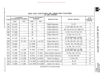
Preventive Maintenance Chart
The Preventive Maintenance Chart lists the scheduled maintenance tasks for the Pro Bike. The chart lists
the time interval when each procedure should be performed, and provides the general steps necessary to
perform the task. In some cases, the chart references detailed maintenance procedures provided later in
.
.
the section.
=
D =Daily W =Weekly M Monthly (depending on the amount of use, Quarterly procedures may need to be
performed more frequently).
.
INTERVAL
W
M
D
I
PROCEDURE
Clean dust and dirt from the unit using a soft, clean cloth dampened with a non-abrasive
liquid cleaner. Give particular attention to the display panel, handlebars, seat, pedals and
heart rate grips (if used).
~
~
Vacuum the floor under and around the unit MAKE SURE that the unit is at its maximum
elevation when vacuuming (or move the unit to another location).
~
Check the display panel, pedals, seat and shroud to ensure they are securely attached to
the unit. Retighten the screws as needed.
~
Tighten the handlebars by turning the four attaching screws.
~
Tighten the pedals to their respective crank arms.
Pro Bike Service Manual
2.2
)
:a-~BY
UN/SEN, /NC.,"_ _
®hVlC
Section 3
Diagnostics
The PRO BIKE contains several customizing and diagnostics features. The customizing feature
allows you to tailor the unit operation to suit your particular needs. Diagnostics features let you view
accumulated data related to machine usage, and check critical operating parameters as an aid in
maintenance and troubleshooting.
These features include:
•
Diagnostic LEDs - Provide and indication of the operating status of the Load Control Board
(LCB) and the alternator.
Display Maintenance Mode - Displays start-up and shut-down service messages as a result of
self-test or when scheduled periodic maintenance is required.
Display Settings Mode - Lets you modify certain operating and display settings for the unit.
Service Settings Mode - Displays accumulated statistical data related to machine usage and
troubleshooting.
Service Messages - Display during machine use if certain electrical failures or out-of-tolerance
conditions are detected.
System Measurements Mode - Lets you monitor critical electrical parameters under both idle
and in-usage to help diagnose.
Contents
Diagnostic LEOs
,
Display Maintenance Mode
Display Settings Mode
Service Settings Mode
Service Messages
System Measurements Mode
3.1
,
3.2
3.3
3.4
3.6
3.7
3.8
Pro Bike Service Manual
ST~BYUNISEN' INC.
_
®~C
Diagnostic LEOs
The Load Control Board (LCB) is equipped with three diagnostic LEOs. These LEOs provide
indications of the operating status of the LCB and the alternator.
The LCB diagnostic LEOs function as follows:
LED
02
FUNCTION
This Led provides a steady series of flashes, at 20-per-second, indicating communication
between the LCB and the display panel is functional. If this LED is off or flashes erratically,
replacement of the LCB, the display panel or the communication cable may be required.
03
This LED provides a steady series of flashes, at one-per-second, indicating the LCB
microprocessor is functional and the loop circuit is operating. If this LED is off or flashes
erratically, replacement of the LCB may be required.
013
This LED is normally off. If alternator output voltage exceeds 19 volts, the LED lights steady on.
This condition will also cause the - Needs Service" message to display (see Display
Maintenance Mode for details).
NOTE: The diagnostic LEOs provide a general indication of certain equipment malfunctions. Refer
to Systems Measurement Mode and in Section 4, Troubleshooting to aid in locating the
most likely cause of the problem.
Pro Bike Service Manual
3.2
ST..n:I..SY
Display Maintenance Mode
UN/SEN. /NC.
_
®liIIlC
The PRO BIKE displays start-up and shutdown service messages if an error is detected during use,
or when periodic maintenance is due.
Start-up Service Messages
The unit performs a self-test at the beginning of every workout. The self-test is initiated as soon as
operation of the unit begins, and continues throughout the duration of the workout. If a failure in an
' clrcUl
. 't or componen t'IS det ect ed one 0 f th e f 0 II oWing
. messages WI"II d'Ispav:
I
eI
ect
ronlc
Key Down
One or more keys on the keypad(s) are stuck in the depressed (on) position;
maintenance service is required. Call Star Trac Customer Support for assistance.
J
Needs Service
Self-test has detected an electronic component failure; maintenance service is
required. Call Star Trac Customer Support for assistance. Specific service
messages describing the equipment malfunction or failure can be accessed and
viewed using the Service Settings feature. Additional troubleshooting information is
provided in Section 4.
Shutdown Service Message
The PRO BIKE displays a " Needs Service" message when a periodic (preventive) maintenance
procedure is due. This message displays for 2-3 seconds at the end of a workout session. Call Star
Trac Customer Support for assistance. Preventive maintenance procedures are outlined in Section 2.
3.3
Pro Bike Service Manual
m - J r : I . . S Y UN/SEN, /NC.
_
®liIIlC
Display Setting Mode
The Display Settings Mode lets you view and modify several unit settings, which affect the way the machine
operates during a workout Use the keypad to enter the Display Settings Mode, view the current settings and
make any desired changes.
To enter the Display Settings Mode:
Press and hold the "Enter", "0" and "1" keys at the same time.
While continuing to hold the "ENTER "0" keys, release the "1" key. The unit will beep once, and the
message "Display Settings" will show in the upper display screen.
3. Release the "Enter" and "0" keys.
1.
2.
Once the unit is in the Display Settings Mode, use the keypad to select and enter changes to unit settings:
KEY
"Scroll" Key
FUNCTION
Press the "Scroll" key to scroll through the display settings and select the setting you
wish to view or change (for each setting, the current value is displayed in the upper
information window). Pressing and holding the "Scroll" key will scroll continuously
through the available settings. When a new value for the setting has been selected,
press the "Scroll" key to save the new value and advance to the next setting.
Up Down
Arrow Keys
Use the "Up-Down Arrow" keys to scroll through the available values for the setting
and to select a new value.
NOTE: To return display settings to their original values after changes have been
made and saved, you must MANUALL Y re-enter the factory-default settings.
"Enter" Key
Press the "Enter" key to exit the Display Settings Mode and return to the standard
operating mode.
Pro Bike Service Manual
3.4
g l R r S Y UNISEN.INC.
Display Settings Mode
_
®lWlC
The following display settings may be changed using the keypad as previously described:
3.5
Setting
Minutes
DefaultV?IUe
60
Units
ENGL
Weight
155
HR
POL (polar)
DHRC
ON
Watts
OFF
Mets
OFF
Lang
ENGL
Description
Values shall be from 1-99. This shall be the maximum
number of minutes for a program. NONE shall be used
for no limit. If counter reaches limit of 99 minutes, it will
roll over to O.
Values shall be ENGL and METR. This shall determine
whether units shall be displayed and received in
English units (Pounds, Miles) or Metric (Kg, Km).
Values shall be 0-350 when UNITS is set to ENGL, and
0-160 when UNITS is set to METRIC. This number is
provided as a default only; user will be prompted to
enter their weight, which is used for calculating total
calories burned.
Values shall be ON and OFF. This shall determine
whether Heart Rate Sensing shall be Active..
Values shall be On and OFF. This shall determine
whether the Heart Rate Control programs shall be
accessible from the HEART KEY.
Values shall be ON and OFF. This shall determine
whether or not a Watts value shall be displayed with
other program statistics at the Info display during a
workout.
Values shall be ON and OFF. This shall determine
whether or not a Mets value shall be
displayed with other program statistics at the text
display during a workout.
Values of ENGL, GER, SPAN, DUTC, FREN, ITAL,
PORT, and SWED shall be available for language.
settings. Prompts in the Info Window shall be
translated to the selected language.
Pro Bike Service Manual
gm,SYUNISEN,INC.
_
®mJlC
Service Settings
The PRO BIKE records and stores usage data which may be used as,an aid in maintaining the unit and
diagnosing malfunctions. The Service Settings Mode lets you view this usage data, as well as software
version numbers and the serial number and date of manufacture for the unit.
To enter the Service Settings Mode:
1. Press and hold the "Enter", "0" and "2" keys at the same time.
2. While continuing to hold the "Enter" and "0" keys, release the "2" key. The unit will beep once, and the
message "Service Settings" will show in the upper information display.
3. Release the "Enter" and "0" keys.
Once the unit is in the Service Settings Mode, use the keypad to view service settings, service messages,
or system
Settjng
Disp Ver
Default Value
x.y
LCB Ver
X.y
Ser Number
Mfg Date
Run Hrs
000000
00/00/00
0
Run Dist
0
Bat Hrs
0
Wall Hrs
0
Key1
0
Key2
Key3
Key4
Key5
Model
0
0
0
0
xxxxxx
Pro Bike Service Manual
Oescription
Values of x.y:x shall be 1-24 and y shall be 0-9. Current
Display software version number shall be built into the
software and shall not be modified from the keypad.
Values of X.y:x shall be 1-24 and y shall be 0-9. Current LCB
firmware version number is built into the LCB software and
shall not be modified from the keypad.
This shall be entered at manufacture time.
This shall be entered at manufacture time.
Values of 0 - 65535. Current number of whole hours of
program time. Value entered from the keypad shall be up to a
4 digit number.
Values of 0-65535. Current number of whole miles of
program distance. Value entered from the keypad shall be up
to a 4 digit number.
Values of 0-65535. Current number of whole hours on the
current battery. Value entered from the keypad shall be up to
a 4 digit number.
Values of 0-65535. Current number of whole hours on wall
power. Value entered from the keypad shall be up to a 4 digit
number.
Values of 0-22. 10 number of key pressed previous to a
NEEDS SERVICE or KEY DOWN condition. *
Values of 0-22. 10 number of key pressed previous Key1. *
Values of 0-22. 10 number of key pressed previous Key2. *
Values of 0-22. 10 number of key pressed previous Key3. *
Values of 0-22. 10 number of key pressed previous Key4. *
Values of "P-Vbike" AND "EE4600". When the model
selection is changed from default, the Disp Ver will
automatically update.
3.6
5r.n:l.SYUNISEN,INC.
_
®liIIlC
Service Messages
The PRO BIKE self-test function monitors critical electrical circuits while a workout is in progress. If a
malfunction or failure in a monitored circuit occurs during a workout, the "Needs Service" message
displays (as described in Display Maintenance Mode), and a specific service message is set. Service
message can be accessed and viewed from the Service Settings Mode.
To view Service Messages:
While in the Service Settings Mode, press the "5" key. The first recorded service message will
display in the upper information display.
Press the "Scroll" key to view additional service messages (if any have been set).
• Press the "Enter" key to exit Service Messages and return to the Service Settings Mode. The
following service messages may be set by the self-test function:
3.7
.. Message
No Comm
0
No Alt
0
Fld Short
0
No Load
0
Low Batt
0
Model Err
0
DefaLJltVaIlJe .
D'E!sctjption
Values of 0-65535. Number of communication failures
recorded for the system. Pressing CLEAR or "0" while
viewing this value shall clear it to O.
Values of 0-65535. Number of alternator failures recorded for
the system. Pressing CLEAR or "0" while viewing this value
shall clear it to O.
Values of 0-65535. Number of field short failures recorded
for the system. Pressing CLEAR or "0" while viewing this
value shall clear it to O.
Values of 0-65535. Number of no load failures recorded for
the system. Pressing CLEAR or "0" while viewing this value
shall clear it to O.
Values of 0-65535. Number of low battery failures recorded
for the system. Pressing CLEAR or "0" while viewing this
value shall clear it to O.
Value of 0-65535. Number of model mismatch errors
recorded for the system. Pressing CLEAR or "0" while
viewing this value shall clear it to O.
Pro Bike Service Manual
g..n:lrSY
®1iIIlC
UN/SEN, /NC."_ _
System Measurements Mode
The System Measurements Mode lets you measure critical voltages in the battery/alternator circuits,
under both idle and operating conditions.
To enter the System Measurements Mode:
• While in the Service Settings Mode, press the "8" key.
• Press the "Scroll" key to view the system measurements available.
• Press the "Enter" key to exit the System Measurements Mode and return to the Service Settings Mode.
MEASUREMENT
Battery Voltage
DESCRIPTION
Measures and displays battery output voltage while the unit is idle. Output voltage
for a normal battery should range between 6.2-7.5 volts.
·
Alternator Voltage
Output voltage below 6.2 volts indicates a low battery charge or a damaged
battery.
Output voltage above 7.7 volts indicates a fault in the Load Control Board.
·Measures
and displays alternator output voltage while the unit is in use. To check
the alternator output voltage:
·
·
Wall Power
Pedal the unit at a speed above 1.5 miles-per-hour.
Alternator output voltage should range between 11 .5-13.5 volts. Voltages
outside this range indicate a fault in the Load Control Board.
Measures and displays the voltage delivered to the unit from an optional
external wall
-
Load Voltage
between 11.0-1 8.0 voltage. The power pack should be replaced if the voltage
is outside this range.
Measures and displays the voltage generated across the workout loading resistor
while the unit is in use. To measure the load voltage:
·
Pedal the unit at a speed above 1.5 miles-per-hour.
·
Load voltage should range between 1.0-10.0 volts. Voltages outside this
range indicate a fault in the Load Control Board.
LED Test
LED test display are accessible by pressing "9" at the start of SERVICE SETTINGS.
The LED test display shall be all LEDs lit in the Profile Window, and "8" characters filling both the Info
Window and the Feedback Window.
Pro Bike Service Manual
3.9
gm,SYUNISEN.,NC.
Section 4
_
®n:IIlC
Troubleshooting
The PRO BIKE incorporates built-in self-test and diagnostic features which assist in diagnosing
electrical system problems.
Section 3: Diagnostics contains the procedures for using these self-test and diagnostic features.
This section contains troubleshooting information for mechanical problems which may occur as a
result of normal usage of the PRO BIKE. Troubleshooting information is presented in chart form.
The Troubleshooting Chart identifies symptoms of problems which may occur, lists the most
probable cause(s) for the problem, and provides suggested remedies to return the unit to operating
condition.
Contents
Troubleshooting Chart...........
No Communication Flowchart............................................................................
No Alternator Output Flowchart
,.
No Alternator Field Flowchart
,
No Load Flowchart..........................................................................................
Low Battery Flowchart
,
Heart Rate Troubleshooting
, '"
Pro Bike Service Manual
4.2
4.4
4.5
4.8
4.10
4.12
4.13
4.1
g.n:l,SYUNISEN"NC._ _
®liIIlC
SYMPTOM
No power to display
Troubleshooting Chart
PROBABLE CAUSE
1. Low or dead battery.
SUGGESTED REMEDY
1. Enter System Measurement
Mode, see Section 3 page
3.9 and check battery
output.
2. Using a volt meter manually
check battery output
voltage. Readings lower
than 6.2 volts indicates a
low battery.
No Polar reading
2. Disconnected or shorted
Communication or Power
cable.
1. Remove top shroud cover.
Check LED's 02 and 03,
verify they flash while
pedaling, see Section 3
page 3.2 for details
3. Faulty LCB.
1. Check all connections to the
LCB. See No Power
Flowchart in this section
page 4.13
4. Faulty display.
1. Remove the display and
check Communication and
Power cables connection.
2. Swap or replace display.
1. Disconnected or faulty Polar 1. Remove the display, check
cable.
polar connector to the
combiner/heart rate board.
2. Connect the polar board
straight into the display
electronics, by-passing the
combiner/heart rate board.
If polar is working replace
the combiner/heart rate
board.
3. No polar readings continue
replace the polar board;
No Contact Heart Rate reading
4.2
1. Disconnected or faulty Heart 1. Remove the display, check
Rate grips or board.
heat rate grip connection to
the grips and heart rate
board.
Pro Bike Service Manual
ST.JI=I..SYUNISEN,INC._ _
Troubleshooting Chart
SYMPTOM
PROBABLE CAUSE
No Contact Heart Rate
(continue)
®1iIIlC
SUGGESTED REMEDY
. 2. Remove the two screws
which supports the heart
rate grips and check
connection.
3. Using a Multi-meter check
continuity between the grips
and the heart rate cables.
Ceasing, hard to pedal
1. Transfer case bearings are
damaged.
1. Loosen or remove the Poly
V belts.
2. Manually by hand rotate the
transfer case pulley, feel for
any loosening or
mechanical grinding
(bearings) as the pulley is
rotated. If the pulley is hard
to turn or completely loose
replace the transfer case.
No resistance
1. Faulty Alternator
1. Check all connections from
the LCB and alternator.
2. Enter System Measurement
Mode, see section 3 page
3.9 and check Alternator..
Voltage. Output voltage
range should be between
11.5 - 13.5. Voltage outside
the this range indicates a
faulty Alternator.
2. Faulty LCB.
1. Enter System Measurement
2. Mode, see section 3 page
3.9 and check Load
Voltage. Output voltage
range should be between
1.0 - 10.0. Voltage outside
the this range indicates a
faulty LCB.
Pro Bike Service Manual
4.3
.sT.Jt:IrSY
®1ftIlC
UN/SEN, I N C . " -
No Communication Flowchart
<8>
NOTE 1: The LCa
panel is secured with
three Phillips head
screws; two located
under the flap from
the rubber grommet,
and the other located
in front of the panel.
NOTE 2: LED 02
provides a steady
series of flashes, at
20-per-second, indicating communication
between the LCa and
the display board. The
LED remains flashing
for 20 seconds after
initial stride.
NOTE 3: You may
temporarily use a 6pin line telephone
exten-sion cable in
place of the
communication cable
to verify if the
communication cable
is defective.
...I
Remove LCB panel.from
front shroud (see Note
i). Locate LED 02
(see Diagram 1).
1
Begin striding. Verify
LED 02 flashes steady
(see Note 2).
Diagram 1
YES
YES
11....__
1
NO
(
I
Remove PROM slot
cover from back of
display (see Diagram 2),
Verify communication
cable is connected to
connector J4.
R_ep_l_ac-:-e_L_c_B_,_ _
@
Stop)
DISPLA Y SIGNAL
CONNECTOR
YES
J,.
Replace the
communication cable
(see Note 3).
Diagram 2
Reconnect the
communication cable.
I
"r
(
Stop)
(
Stop)
\
4.4
Pro Bike Service Manual
INC.~
m-m..SYUNISEN,
-
®1ftI\C
No Alternator Output Flowchart
NOTE 1: Press and
hold the "Enter", "0"
and "2" keys at the
same time. While
holding the "Enter"
and "0" keys, release
the "2" key. The unit
will beep once and the
message "Service
Settings" will display.
Release the "Enter"
and "0" keys; press
the "8" key. The
message
"Measurements" will
display.
Engage "System
Measurement Mode"
(see Note 1). Use
"Scroll" key to select
Alternator Voltage.
Begin striding (display
shows alternator output
voltage while in use).
Verify voltage is between
10.5 - 13.5 volts.
NO
NOTE 2: Remove
eight Phillips head
screws from the front
shroud. Lift the front
shroud off the unit.
NOTE 3: From the
"System Measurements" mode, press
the "Enter" key to
return to the "Service
Settings" mode. From
the "Service Settings"
mode, press the
"Enter" key to return
to the "Manual" mode.
Re-engage the "Manual
Mode" (see Note 3).
Press the "Scroll" key
until speed is displayed.
Pedal the unit at a
seed of 1.5 MPH.
Take an output voltage
reading at the alternator
(see Note 4 and
Diagram 1). Verify
voltage is between
9 - 10 volts.
NO---)
YES
I
@
NOTE 4: Place the
red voltmeter probe
on the alternator red
wire connector
labeled "B"; place the
black volt-meter probe
on the alternator black
wire/ nut labeled "E".
I
Replace the alternator.
(
YES
I
@
1 ,)
Stop
RED
\rIHITE
BLACK
NOT USED
YELLO\rl
GREEN
Diagram 1
Pro Bike Service Manual
4.5
ST'.JI'=I..SYUNISEN,INC._
®1iIIlC
NOTE 5: Place the
red voltmeter probe
into the red wire at the
Lea J4 connector;
place the black
voltmeter probe on
the alternator black
wire/nut labeled "E".
No Alternator Output Flowchart
Take a voltage reading
at the alternator and
LeB (see Note 5 and
Diagram 2). Verify
voltage is between
9 -10 volts.
NOTE 6: Place the
red voltmeter probe
on the alternator
yellow wire/ nut; place
the black voltmeter
probe on the
alternator black
wire/nut labeled "E".
Diagram 2
YES
Take a voltage reading
at the alternator (see
Note 6 and Diagram 3).
Verify voltage is between
8 - 9 volts.
Replace the wire
harness.
@-------------,
YES
RED
BLACK
YELLOW'
Diagram 3
4.6
GREEN
Pro Bike Service Manual
gJR,BYUNISEN,INC._ _ -
®1iIIlC
No Alternator Output Flowchart
NOTE 7: Place the
red voltmeter probe
into the yellow wire at
the Lea J4 connector;
place the black
voltmeter probe on
the alternator black
wire/nut labeled "E".
a
Take voltage reading
at the alternator and
LCB (see Note 7 and
Diagram 4). Verify
voltage is between
8 - 9 volts.
RED
W'HITE
BLACK
NOT USED
YELLOW'
GREEN
Diagram 4
YES
I
Replace the cable
harness.
(
Pro Bike Service Manual
Stop)
Replace the LeB.
(
Stop)
4.7
g./R..SYUNISEN,INC._
®lftIlC
No Alternator Field Flowchart
Remove the LCB panel
from the front
shroud (see Note 2)
NOTE 1: Press and
hold the "Enter", "0"
and "2" keys at the
same time. While
holding the "Enter"
and "0" keys, release
the "2" key. The unit
will beep once and the
message "Service
Settings" will display.
Release the "Enter"
and "0" keys; press
the "8" key. The
message
"Measurements" will
display.
Engage "System
Measurement Mode"
(see Note 1). Use
"Scroll" key to select
Alternator Voltage.
Begin striding (display
shows alternator output
voltage while in use).
Verify voltage is between
10.5 - 13.5 volts.
NO
NOTE 2: The LCa
panel is secured with
three Phillips head
screws; two located
under the flap from
the rubber grommet,
and the other located
in front of the panel.
NOTE 3: From the
"System Measurements" mode, press
the "Enter" key to
return to the "Service
Settings" mode. From
the "Service Settings"
mode. press the
"Enter" key to return
to the "Manual" mode.
Re-engage the "Manual
Mode" (see Note 3).
Press the "Scroll" key
until speed is displayed.
Pedal the unit at a
seed of 1.5 MPH.
Take a voltage reading
at the LCB (see Note 4
and Diagram 1). Verify
voltage is between
5.5 - 6.5 volts.
NO~
Replace the LCB.
YES
,l,.
(
Stop)
NOTE 4: Place the
red voltmeter probe
on LCa test point TP8
FIELDDRV; place the
black voltmeter probe
on LCa test point
TP11 AGND.
TP11
o
Oiagram 1
Pro Bike Service Manual
4.8
m-.JR.BYUNISEN,
®liIIlC
No Alternator Field Flowchart
-
IN~'-
RED
NOTE 5: Remove
eight Phillips head
screws from the front
shroud. Lift the front
shroud off the unit.
NOTE 6: Place the
red voltmeter probe
on the alternator
yellow wire/ nut; place
the black voltmeter
probe on the
alternator black
wire/nut labeled "E".
BLACK
Replace the front
shroud (see Note 5).
Take a voltage reading
at the alternator (see
Note 6 and Diagram 2).
Verify voltage is
between 9 - 10 volts.
YELLOW'
GREEN
Diagram 2
NOTE 7: Place the
red voltmeter probe
into the yellow wire at
Lea connector J4;
place the black
voltmeter probe on
the alternator black
wire/nut labeled "E".
NO
Take a voltage reading
at the alternator and LCB
(see Note 7 and Diagram
3). Verify voltage is
between 8 - 9 volts.
Diagram 3
Replace the alternator.
NO--'
Replace the cable
harness.
YES-' Replace the alternator.
4.9
-{ Stop )
-{ Stop )
Pro Bike Service Manual
~.lRrBYUNISEN,
INC._
®1iIIlC
No Load Flowchart
RED
1A
"'HITE
NOTE 5: Remove
eight Phillips head
screws from the front
shroud. Lift the front
shroud off the unit.
NOTE 6: Place the
red voltmeter probe
on the alternator
yellow wire/ nut
labeled EXC; place
the black voltmeter
probe on the
alternator black
wire/nut labeled "E".
BLACK
Replace the front
shroud (see Note 5).
Take a voltage reading
at the alternator (see
Note 6 and Diagram 2).
Verify voltage is
between 8 - 9 volts.
YELLO'"
GREEN
Diagram 2
NOTE 7: Place the
red voltmeter probe
into the yellow wire at
LCa connector J4;
place the black
voltmeter probe on
the alternator black
wire/nut labeled "E".
NO
Take a voltage reading
at the alternator and LCB
(see Note 7 and Diagram
3). Verify voltage is
between 8 - 9 volts.
Diagram 3
Replace the alternator.
NO~
'-------yES-.
4.11
Replace the cable
harness.
Replace the alternator.
Pro Bike Service Manual
Low Battery Flowchart
•
NOTE 1: Press and
hold the "Enter", "0"
and "2" keys at the
same time. While
holding the "Enter"
and "0" keys, release
the "2" key. The unit
will beep once and the
message "Service
Settings" will display.
Release the "Enter"
and "0" keys; press
the "8" key. The
message
"Measurements" will
display.
Engage "System
Measurement Mode"
(see Note 1). Use
"Scroll" key to select
Battery Voltage.
Begin striding (display
shows battery voltage
while in use). Verify
voltage is between
6 - 7 volts.
Replace the LeB.
YES
@
YES
NO-{ Stop)
Battery charge is low
or battery is faulty.
Refer to the procedures
on page 3-7 to service
the battery.
Pro Bike Service Manual
4.12
~.n:IrBY
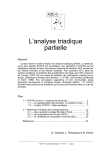
Heart Rate
UN/SEN. /NC.'-_
®1iII\C
Symptom:
Intermittent or no heart rate readings.
STEP 1:
Confirm the user is using the grips correctly. Hands must be completely making contact
with the heart rate plates.
STEP 2:
An excessively tight grip on the heart rate grips can cause erratic readings. The
probability of the erratic readings can be therefor be lessened by:
--- reduce upper torso movement.
--- a proper grasp on the grips.
--- clean hands.
--- clean grips.
Excessive foreign matter (dirt or hand lotions) on the hands can biochemical generate
electrical interference which will cause erratic readings.
STEP 3:
No heart rate is registered check connections and continuity between the grips.
--- Remove the display and verify that the heart rate cables are connected.
--- Remove the heart rate cover plates and check connection, see diagram 1.
, 4.13
Pro Service Manual
~.n:I,BYUN1SEN'
lNC."_
®n:IIlC
Heart Rate
--- Using a Multi- meter check the continuity between the heart rate grips,
see diagram below.
--- Disconnect the heart rate cables. Using the Multi-meter check continuity
between the heart rate grips and cables. Place the red meter on the red
cable and using the black meter probe test each heart rate grip plate for
continuity. One of the plates should register. Perform the same test with
black heart rate cable.
•
'Pro Service Manual
4.14
g J r : l , S Y UN/SEN, /NC.'-_ _
®liIIlC
Section 5:
Parts Replacements
Should the PRO BIKE experience a problem requiring replacement of a specific part, the
following procedures will help and instruct in the replacement of major parts.
Contents
Crank Bearing Replacement..........
Transfer Case Replacement..
Alternator Replacement
Battery Replacement...
Display Replacement
PROM Replacement
Heart rate grips Replacement
Pro Bike Service Manual
5.2
5.5
5.9
6.3
6.4
6.6
6.8
5.1
g - - J I ' = I , S Y UN/SEN, /NC...._ .
®n:IIlC
Crank Bearings Replacement
Tools:
•
•
•
•
•
•
•
•
1/8 Hex keys
1 1/4 Open-end wrench
14mm Open-end wrench
Adjustable crescent wrench
Punch
Flat and Phillips head screwdriver
Mallet
Needle-nose pliers
Time Required: 20 Minutes
Procedure: Remove both pedals
1. Using a 14-mm open-end wrench, hold the opposite side of
crank arm and loosen pedal. Note: The pedals loosen by turning to
the right.
( See page 5.7 in this section Pedal Replacement for more details)
2. Repeat the same step for the opposite side.
Remove shroud
1. Using a 1/8 hex key, remove the shroud screws. ( 8 total)
2. Using a Phillips screwdriver remove the side shroud screws. (4 total)
3. Tum the crank arm toward the front of the bike. Left side first Gently slide the
shroud towards the front of the bike until the shroud has been removed
Do the same to the right side of the bike.
5.2
Pro Bike Service Manual
ST.n:IrSY
®WIIlC
UN/SEN. /NC.,"'_ _
~rank
Bearings Replacement
4. Bend the tabs up on locking retaining washer (See diagram for picture of part
#8). Use a pair of needle nose pliers or a flat head screwdriver to bend both
tabs up.
5. Slide the crank belt off the crank pulley. (#1).
6. Using a 1 ~ open-end or an adjustable crescent wrench remove, the crank
locking nut (#7) and slide the locking retaining washer completely off.
Remember to loosen, tum to the right.
II
7. Using a 1 ~ open-end or an adjustable cres~ent wrench, remove conical
bearing nut (#6) completely.
II
8. Loosen the outer bearing Nut (#10) with a Channel lock wrench.
9. Remove the left side bearing from the bearing housing.
10. Remove the inner bearing spacer sleeve from the crank housing (#11).
11. Remove the outer bearing spacer sleeve from the crank housing (#11).
12. Remove the crank from the bearing housing. The bearing may come out with
crank arm if not, use a flat head screw driver to pry the bearing out.
Install new spacers and bearings
13. Grease both sides of the bearing housing. Use black lithium grease and apply
to both bearing cups.
14. Slide the bearing on the crank.
15. Slide the crank arm, starting from the right side through the bearing housing.
16. Insert the first bearing (#3) through the crank arm and crank housing.
17. Insert both inner and outer bearing spacer sleeves (#11) through crank arm in
the crank housing.
18. Insert second bearing (#3) through the crank arm in the crank housing.
19. Apply a small drop of Loctite (RED) with a channel lock wrench to 15-20Ibs.
,.
Pro Bike Service Manual
5.3
ST...n-:I,SY
UN/SEN. /NC.
®n:IIlC
_
Crank Bearings Replacement
20. Screw in the conical bearing nut (#6) first. Tighten first nut on crank only
enough to align t~e bearing (no more then finger tigqt), then back the nut off
1/8 tum. Make sure the is no play from side to side. Remember to tighten, tum
to the left.
21. Insert the locking retairTlng washer (#8). There is a flat tab on the inside hole,
that tab will slide into the slot on the crank threads.
22. Apply a small drop Loctite (243) to threads on the crank arm.
23. Screw in the locking crank nut (#7) and tighten.
24. Using a 1 ~ open end or adjustable crescent wrench tighten nut. Ensure the
conical bearing nut does not tighten or loosen during this process.
25. After tightening the crank-locking nut, spin crank and E?nsur~ that the crank
spins freely. The crank should spin a couple of times with finger pressure.
If it does not spin freely, adjust locking nut in a counter-clock wise direction.
26. Grab the end of the crank and move the crank towards and away from the bike
to check for play. If there is any play, tighten conical bearing nut, but be sure
.not to over tighten.
27. Use a punch or a flat head screwdriver and mallet bend down retaining washer
tabs one on first nut and one on second nut.
28. Slip the crank belt back on to the crank pulley.
Re-install shroud
1. Gently slide the shroud towards back of the bike until shroud is installed.
2. Using a 1/8 Hex key screw in the shroud screws. ( 8 total)
3. Using a Phillips screwdriver screw in the side shroud screws. ( 4 total)
4. Do the same to the right side of bike.
Re-install both pedals
5.4
Pro Bike Service Manual
m--mrSYUNISEN,INC.
_
®n:IIlC
ransfer Case Replacement
Tools:
•
.•
•
1/16 Allen Wrench
9/16 Socket
9/16 Open End Wrench
•
Rubber MalletJHarnmer
•
Retaining Clip Tool or small flat head screwdriver and needlenose pliers
Time Required: 20 minutes
Procedure: Remove transfer case.
1. Remove screws from the bike shroud using the 1/16 allen wrench. Set the
shroud and screws aside.
2. Remove the alternator belt by gently pushing it off of the 9/12" pulley.
(See Diagram A )
3. Loosen the top nut on transfer case. (See Diagram B )
4. Remove the drive belt by slipping it off of the crank pulley and transfer case
pulley. (See Diagram C)
5. Remove the 91/2" pulley by removing the c-ring retaining clip. Use the
retaining clip tool or the small flat head screw driver and needlenose pliers.
Alternator Belt
Pulley
•
Pro Bike Service Manual
5.5
g/R,SYUN,SEN.,NC...._.
®hVlC
Transfer Case Replacement
Top Nut
Bottom Nut
Diagram B
6. Loosen the bottom nut on the transfer case and remove both the top and
bottom bolts, washers and nuts. (See Diagram B)
7. Remove the transfer case.
5.6
Pro Bike Service Manual
.sr-..n:IrSY /NC."__
®1ftIlC
UN/SEN.
Transfer Case Replacement
Drive Belt
Pulley
Diagram C
8. Place the new transfer case into place. The crank pulley shroud be facing
towards the right side.
9. Replace the transfer case bolts. The long bolt goes on the bottom and the
.
small bolt on the top. Slide the drive belt back on pUlle~ls.
10. Tighten the bottom bolt on the transfer case first with the 9/16 open-end .
wrench.
11. Tighten the top bolt again until finger tight to allow for proper tensioning.
12. Using a rubber mallet or hammer tap the top end of the transfer case to tighten
the drive belt. Proper tension should be 85 Ibs +/- 5 Ibs.
13. When proper tension is achieved tighten top bolt completely with the 91/6
open-end wrench.
14. Check the alignment of the belt to pulleys. Adjust the transfer case pulley by
loosening the set screws on the transfer case pulley. When proper alignment
is obtained re-tighten the set screws.
Pro Bike Service Manual
5.7
gJt:l,SYUNISEN.INC. . ._ _
®n:IIlC
Transfer Case Replacement
15. Replace the 91/2" pulley on the transfer case. Put the flush side of pulley
against the transfer case. The recessed side out for the c-ring retainer dip.
16. Replace the retaining clip on the shaft to hold pUlley in place. Make sure the
pulley moves when you tum the crank.
17. Walk the alternator belt back on the pulleys.
18. Replace shroud and screws using the 1/26 allen key.
5.8
Pro Bike Service Manual
s r - . J I ' : I , S Y UNISEN. INC."_ _
...
Alternator Replacement
®n:IIlC
Tools:
•
•
•
•
•
•
Phillips head screw driver
12mm socket
10mm socket
14mm socket
W' socket
~"socket
Time Required:
1Hr.
Procedure: Remove Pedals
1. Place right foot on the right pedal and apply entire body weight.
2. simultaneously rotate opposite pedal mounting bolt in counter clockwise
direction.
Remove shroud
1. Using the 1/8" hex wrench and the Phillips head screwdriver. Remove the 9
screws holding the shroud in place.
2. Be cautious of the pedal cranks as the shroud is removed.
Remove Alternator Belt
1. Move to the left side of the bike and note the Transfer Case Assembly.
2. Slowly rotate the large clutch pulley counter clockwise while simultaneously
working the belt grooves to the outside of the pulley. (See Diagram A)
Pro Bike Service Manual
5.9
ST1RrSYUNISEN"NC. . ._ _
®WIIlC
Alternator Replacement
Remove the RPM Sensor
1. First, note the gapping between the rpm sensor and the rpm disc or "f)ywheel".
The gap should-be no greater than 1 / 3 2 " . "
2. With the ~" socket, remove the nut located directly behind the rpm sensor
mounting bracket.
3. Then remove the
~"
bolt on the face of the rpm sensor bracket.
4. Let the rpm sensor remain attached to the wiring harness and set aside the Y:z"
nut and bolt.
5. Refer to Figure A prior to removing wires.
6. Remove wires in clockwise sequence.
7. With the12mm socket remove the large red positive wire from Terminal B.
8. With the 10mm socket, remove the black ground wire from the post directly
underneath Terminal B on the altemator casing.
9. With the 10mm socket, remove the narrow green field wire from Terminal S.
10. Using the 10mm socket, remove the black ground wire from Terminal EXC.
Remove the Alternator
1. Using the 14mm socket, loosen the nut on the tension bracket. Do not remove
completely.
2. With the 7/8" socket, loosen and remove the large nut on the right side of the
alternator. Be careful to note the presence of a washer and lock washer
associated with this nut.
3. Remove the }2" bolt securing the alternator to the tension bracket. Note the
presence of a washer at the bolt head and a spacer (on the Upright Bike only)
between the bracket and the alternator.
4. Loosen and remove the %" nut from the main alternator mount.
5. Remove the ~" bolt from the main alternator mount. Be careful to cradle the
alternator with one hand as the last bolt is being removed to prevent it from
falling and damaging the frame.
6.0
Pro Bike Service Manual
m - m r S Y UN/SEN, INC.
-
Alternator Replacement
_
®n:rAC
Re-installation Procedure
1. Re-position Alternator on to support member.
2. Retrieve the 3/8'" bolt, position washer and insert from the right side of unit
3. On the Upright bike only, be sure to include the thick spacer between the
alternator and the support member.
4. Position the alternator and tension bracket together and insert the large %'" bolt
from the left side of the unit to the right.
5. Again, note the presence of the spacer on the Upright Bike only.
Attach RPM Sensor.
1. Using the other 3/8" bolt and nut, secure the RPM Sensor to the casing of the
alternator.
2. Tighten the nut and bolt finger-tight and position the sensor lobe to 1/32"
distance away from the large sensor discJflywheel. (1/32" is about equal to the
thickness of one business card.)
3. Tighten RPM sensor bolt.
Attach Alternator Belt.
1. Place the alternator belt around the alternator flywheel/pulley assembly.
2. Loop the other end around the 9.5" crank pulley.
3. While pressing the belt grooves and crank grooves together, slowly rotate the
crank, allowing the alternator belt to seat on to the crank.
4. Make sure all grooves are aligned. Adjustment is easily made by pressing to
the side of the belt and slowly rotating crank.
5. Adjust belt tension using the Y:z" socket. Tension is rated at 1001bs. The
tension can be accurately approximated by tightening the forward facing
tension bolt until there is no more than %" inch of up and down play in the belt.
6. Tighten the large bolt and nut securing the alternator to the tension bracket
with the 7/8" and ~" sockets.
•
Pro Bike Service Manual
6.1
srJl:lrSYUNISEN1INC. . ._
®7iIIlC
Alternator Replacement
Re..wire the Alternator.
",..,......
/
-
~
""'RED
"-
""HITE
BLACK
YELLO""
Replace Motor Shroud and Pedals.
1. Be cautious of the extended pedal cranks when replacing the shroud.
2. Using the 1IS" Allen Wrench and the Phillips Head scre'Ndriver, fasten all
shroud screws.
3. Using the 14mm open end 'M"ench or Crescent Wrench, secure pedal
shoulder bolts on to pedal cranks.
6.2
Pro Bike Service Manual
ST..IRrSYUNISEN.INC. . ._
Battery Replacement
®7iVlC
----.,--------------------Tools
•
Phillips head screwdriver
Time Required:
5 minutes
Procedure: Disconnect the battery
1. Disconnect the red (+) cable and the black (-) cable.
/
Remove screws
1. Using the Phillips head screw driver remove the two screws supporting the
battery to the frame. (See diagram)
Install Battery
1. Using the Phillips head screwdriver re-install the two screws through
the battery to the frame.
Pro Bike Service Manual
6.3
g..IR..SYUNISEN"NC.,
_
®7iIIlC
Display Replacement
Tools
•
1/16-inch Allen Wrench
Procedure: Remove the display board
1. Using a 1/16-inch Allen Wrench, carefully remove the 7 screws from the
rear of the display panel mount. It's important to use both hands so that the
display board doesn't fall and damage any connections.
(See diagram below. )
2. Carefully disconnect the heart rate cables, power cable and the
Display signal cable from the back of the display and gently lay the panel
down.
-
--
/
/
'\
\
\
6.4
Pro Bike Service Manual
ST..n:I.SY
®hVlC
UN/SEN, /NC."_ _
Display Replacement
Re-install Procedure
1. Using both han"ds to support the display board carefully re-connect the heart rate cables,
power cable and display signal cable. (See diagram below for connection layout)
2. Carefully supporting the display board re-install the 7 Allen screws using the 1/16 -inch
Allen Wrench.
DISPLAY PO\o/ER
CONNECTOR
DISPLAY SIGNAL
CONNECTOR
NOT USED
CENTER KEYPAD
CONNECTOR
CARDIO
CONNECTOR
LEFT KEYPAD
CONNECTOR
D
ENSURE CONN
IS SHUNTED
RIGHT KEYPAD
CONNECTOR
HEART RATEDISPLAY
CONNECTOR
Pro Bike Service Manual
CONTACT PLATES
CONNECTOR
DISPLAY BOARD
CONNECTORS
6.5
ST.lRrSY
®'JiIIlC
UN/SEN, /NC. _ _-
PROM Replacement
Tools
•
•
Small flat screwdriver
PLCC Extractor
(This spring-assisted chip extractor tool is especially designed for safe
removal of PLCC IC's from 18 to 124 pins. This tool can be purchase at any
electronic store or through Star Trac Product Support.)
Procedure: Remove the PROM
1. Locate the small back panel located on the back of the display mount
supported by a single screw.
2. Using the flat screwdriver loosen, not remove the single screw. Gently slide
the back plate to view the PROM socket.
3. Using the extractor carefully remove the PROM from the back of the display.
It's critical that when using the extractor that you gently press to release the
chip from its socket.
I
I
/
/
Diagram 1: Shows the display without the backing plate only as an example of
the location of the chip.
6.6
Pro Bike Service Manual
g J t : l , S Y UN/SEN, /NC.,
PROM Replacement
_
®7iIIlC
•
Diagram 2: Shows the location and how to remove the chip.
Procedure: Re-install the PROM
1. The new PROM will have a sticker showing the software version. Carefully
pull back the sticker to locate the directional indicator ( circular groove located
on the center top of the chip)
2. Using your index finger and thumb carefully position the new chip with the
directional indicator lined-up with the arrow located on the printed circuit
board (display electronic). Carefully using your thumb apply gentle pressure
so that the chip is inserted into the chip socket on the printed circuit board.
3. Reposition the back panel. Using the flat screwdriver tighten down the single
screw.
Pro Bike Service Manual
6.7
gJR,SYUNISEN"NC.
®n:IIlC
_
Heart Rate Grip Replacement
Tools
•
•
•
1/16-inch Allen Wrench
Phillips Head Screwdriver
String or Scotch Tape
Procedure: Remove the display board
1. Using a 1/16-inch Allen Wrench, carefully remove the 7 screws from the rear
of the display panel mount. It's important to use both hands so that the
display board doesn't fall and damage any connections.
(See diagram below)
2. Carefully disconnect the heart rate cables, power cable and the Display signal
cable from the back of the display and gently lay the display panel down.
-
--
/
/
"
\
\
6.8
Pro Bike Service Manual
gJl:l,SY
~~art
--
Rate Grip Replacement
UN/SEN, /NC.,
_
®n:IIlC
Procedure: Remove the heart rate grips
1. Using a Phillips head screwdriver, remove the 2 screws which support the
heart rate plates to the handlebar. Do this for both the Left and Right heart
rate grips.
(See diagram below)
2. Carefully disconnect the heart rate cables from the back of the heart rate
plates.
3. Remove the plastic end caps from the tips of the handlebar.
(See diagram below)
RIGHT HAND
LEFT HAND
4. Attach the new cables with the old by using string or Scotch Tape and gently
pull the old cable out from the back of the display post.
Pro Bike Service Manual
6.9
. s r r J l ' = l . . S Y UNISEN, INC."_ _
®7iIIlC
~QClrtRat~GripReplacement
Procedure: Re-install the heart rate grips
1. Carefully pull t~e connector plugs through the fro,nt handlebar holes.
2. Re-connect the heart rate cables to the heart rate plates. Using the Phillips
head screwdriver re-install the 2 screws, which attach the heart rate plates to
the handlebar. Do this for both the Left and Right grips.
3. Using both hands to support the display board, carefully re-connect the heart
rate cables, power cable and display signal cable.
(See diagram below)
4. Carefully supporting the display board re-install the 7 Allen screws to the back
of the display using the 1/16-inch Allen Wrench.
DISPL.~ Y POVER
CONNECTOR
DISPLAY SIGNAL
CONNECTOR
NOT USED
CENTER KEYPAD
CONNECTOR
CARDIO
CONNECTOR
LEFT KEYPAD
CONNECTOR
D
ENSURE CONN
IS SHUNTED
RIGHT KEYPAD
CONNECTOR
HEART RATEDISPLAY
CONNECTOR
7.0
CONTACT PLATES
CONNECTOR
DISPLA Y BOARD
CONNECTORS
Pro Bike Service Manual