1
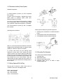
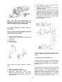
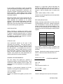
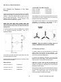
Model TA-10/270 H
PREDATOR
AC/DC CC/CV Welding Generator
STICK
MIG
AUXILIARY POWER
Service Manual
4/1/02
Manual No. 430429-493
GENERAL INFORMATION
2
Table of Contents
SECTION 1: GENERAL INFORMATION ............................................................................................................ 6
1.01 Notes, Cautions and Warnings.......................................................................................................................... 6
1.02 Important Safety Precautions ............................................................................................................................ 6
1.03 Publications ........................................................................................................................................................ 7
1.04 Note, Attention et Avertissement...................................................................................................................... 8
1.05 Precautions De Securite Importantes ................................................................................................................ 8
1.06 Documents De Reference................................................................................................................................10
SECTION 2: TECHNICAL SPECIFICATIONS...................................................................................................11
2.01 Specifications ....................................................................................................................................................11
2.02 Volt-Amp Curve ...............................................................................................................................................11
2.03 Duty Cycle.........................................................................................................................................................11
2.04 Front Panel Descriptions ..................................................................................................................................12
2.05 Dimensions and Weight ...................................................................................................................................13
2.06 Maximum Welding Generator Operating Angles...........................................................................................13
2.07 Installing Welding Generator ...........................................................................................................................13
2.08 Location.............................................................................................................................................................13
2.09 Air Flow Clearance...........................................................................................................................................14
2.10 Generator Auxiliary Power System .................................................................................................................15
2.11 Wiring Optional 230 Volt Plug........................................................................................................................15
2.12 Grounding The Generator ................................................................................................................................15
2.13 When Connecting To Home, Shop, or Farm Wiring......................................................................................16
2.14 Auxiliary Power Requirements........................................................................................................................16
2.15 Simultaneous Welding and Power...................................................................................................................18
2.16 Selecting and Preparing Weld Output Cables .................................................................................................18
SECTION 3: TROUBLE SHOOTING GUIDE ....................................................................................................20
3.01 There Is No Auxiliary Voltage and/or Welding Current ................................................................................20
3.02 The Generator Is De-Energized when Load is connected ..............................................................................21
3.03 Excessive Fall of Voltage When The Load is Connected...............................................................................21
3.04 Single Phase Receptacle Out Of Balance When at Idling ..............................................................................21
3.05 Insufficient Welding Current............................................................................................................................21
3.06 The Battery Runs down Frequently .................................................................................................................22
SECTION 4: CIRCUIT TESTING..........................................................................................................................23
Date 04/01/02
3
Manual
4.01 Checking the Resistance of the Stator Windings.............................................................................................23
4.02 Replacing the Stator..........................................................................................................................................23
4.03 Excitation Capacitors........................................................................................................................................24
4.04 Output Rectifier.................................................................................................................................................24
4.05 Auto Idle Circuit ...............................................................................................................................................24
4.06 Engine Oil Shut-Down Circuit Tests. ..............................................................................................................25
4.07 Engine Charge Circuit Shut-Down Test..........................................................................................................25
SECTION 5: PARTS LIST.......................................................................................................................................26
5.01 Revision A & B.................................................................................................................................................26
5.02 Revision C.........................................................................................................................................................30
5.03 Revision D.........................................................................................................................................................40
5.04 With Kohler Engine..........................................................................................................................................48
5.05 Common Engine Part Numbers .......................................................................................................................54
5.06 Propane Engine Conversion Parts....................................................................................................................55
SECTION 6: SCHEMATICS ...................................................................................................................................57
Revision A.................................................................................................................................................................57
Revision B .................................................................................................................................................................58
Revision C .................................................................................................................................................................59
Revision D.................................................................................................................................................................60
Revision with Kohler Engine ...................................................................................................................................61
APPENDIX A ..............................................................................................................................................................62
GENERAL INFORMATION
4
Date 04/01/02
5
Manual
when cutting or welding any metals which may
contain one or more of the following:
SECTION 1: GENERAL INFORMATION
1.01 Notes, Cautions and Warnings
Throughout this manual, notes, cautions, and warnings
are used to highlight important information. These
highlights are categorized as follows:
NOTE
An operation, procedure, or background
information which requires additional emphasis or
is helpful in efficient operation of the system.
CAUTION
A procedure which, if not properly followed, may
cause damage to the equipment.
WARNING
A procedure which, if not properly followed, may
cause injury to the operator or others in the
operating area.
Antimony
Arsenic
Barium
Beryllium
Cadmium
Chromium
Cobalt
Copper
Lead
Manganese
Mercury
Nickel
Selenium
Silver
Vanadium
• Always read the Material Safety Data Sheets
(MSDS) that should be supplied with the material
you are using. These MSDSs will give you the
information regarding the kind and amount of
fumes and gases that may be dangerous to your
health.
• For information on how to test for fumes and gases
in your workplace, refer to item 1 in Subsection
1.03, Publications in this manual.
• Use special equipment, such as water or down
draft welding/cutting tables, to capture fumes
and gases.
• Do not use the welding torch in an area where
combustible or explosive gases or materials are
located.
• Phosgene, a toxic gas, is generated from the vapors
of chlorinated solvents and cleansers. Remove all
sources of these vapors.
1.02 Important Safety Precautions
WARNING
OPERATION AND MAINTENANCE OF ARC
WELDING
EQUIPMENT
CAN
BE
DANGEROUS AND HAZARDOUS TO YOUR
HEALTH.
To prevent possible injury, read, understand and
follow all warnings, safety precautions and
instructions before using the equipment. Call 1603-298-5711 or your local distributor if you have
any questions.
GASES AND FUMES
ELECTRIC SHOCK
Electric Shock can injure or kill. The arc welding
process uses and produces high voltage electrical
energy. This electric energy can cause severe or fatal
shock to the operator or others in the workplace.
• Never touch any parts that are electrically “live” or
“hot.”
• Wear dry gloves and clothing. Insulate yourself
from the work piece or other parts of the welding
circuit.
• Repair or replace all worn or damaged parts.
Gases and fumes produced during the Arc
welding/cutting process can be dangerous and
hazardous to your health.
• Extra care must be taken when the workplace is
moist or damp.
• Keep all fumes and gases from the breathing area.
Keep your head out of the welding fume plume.
• Install and maintain equipment according to NEC
code, refer to item 4 in Subsection 1.03,
Publications.
• Use an air-supplied respirator if ventilation is not
adequate to remove all fumes and gases.
• Disconnect power source before performing any
service or repairs.
• The kinds of fumes and gases from the arc
welding/cutting depend on the kind of metal
being used, coatings on the metal, and the
different processes. You must be very careful
• Read and follow all the instructions in the
Operating Manual.
GENERAL INFORMATION
6
• Keep helmet and safety glasses in good condition.
Replace lenses when cracked, chipped or dirty.
FIRE AND EXPLOSION
Fire and explosion can be caused by hot slag, sparks, or
the arc weld.
• Protect others in the work area from the arc rays.
Use protective booths, screens or shields.
• Use the shade of lens as recommended in
Subsection 1.03, item 4.
• Be sure there is no combustible or flammable
material in the workplace. Any material that
cannot be removed must be protected.
1.03 Publications
• Ventilate all flammable or explosive vapors from
the workplace.
Refer to the following standards or their latest revisions
for more information:
• Do not cut or weld on containers that may have
held combustibles.
1.
• Provide a fire watch when working in an area
where fire hazards may exist.
• Hydrogen gas may be formed and trapped under
aluminum workpieces when they are cut
underwater or while using a water table. DO
NOT cut aluminum alloys underwater or on a
water table unless the hydrogen gas can be
eliminated or dissipated. Trapped hydrogen gas
that is ignited will cause an explosion.
NOISE
Noise can cause permanent hearing loss.
Arc
welding/cutting processes can cause noise levels to
exceed safe limits. You must protect your ears from
loud noise to prevent permanent loss of hearing.
• To protect your hearing from loud noise, wear
protective ear plugs and/or ear muffs. Protect
others in the workplace.
• Noise levels should be measured to be sure the
decibels (sound) do not exceed safe levels.
• For information on how to test for noise, see item 1
in Subsection 1.03, Publications, in this manual.
ARC WELDING RAYS
Arc Welding/Cutting Rays can injure your eyes and
burn your skin. The arc welding/cutting process
produces very bright ultra violet and infra red light.
These arc rays will damage your eyes and burn your
skin if you are not properly protected.
• To protect your eyes, always wear a welding
helmet or shield. Also always wear safety glasses
with side shields, goggles or other protective eye
wear.
• Wear welding gloves and suitable clothing to
protect your skin from the arc rays and sparks.
7
OSHA, SAFETY AND HEALTH STANDARDS,
29CFR 1910, obtainable from the Superintendent of
Documents, U.S. Government Printing Office,
Washington, D.C. 20402
2. ANSI Standard Z49.1, SAFETY IN WELDING AND
CUTTING, obtainable from the American Welding
Society, 550 N.W. LeJeune Rd, Miami, FL 33126
3.
NIOSH, SAFETY AND HEALTH IN ARC
WELDING AND GAS WELDING AND CUTTING,
obtainable from the Superintendent of Documents,
U.S. Government Printing Office, Washington, D.C.
20402
4. ANSI Standard Z87.1, SAFE PRACTICES FOR
OCCUPATION AND EDUCATIONAL EYE AND
FACE PROTECTION, obtainable from American
National Standards Institute, 1430 Broadway, New
York, NY 10018
5. ANSI Standard Z41.1, STANDARD FOR MEN’S
SAFETY-TOE FOOTWEAR, obtainable from the
American National Standards Institute, 1430
Broadway, New York, NY 10018
6. ANSI Standard Z49.2, FIRE PREVENTION IN THE
USE OF CUTTING AND WELDING PROCESSES,
obtainable from American National Standards
Institute, 1430 Broadway, New York, NY 10018
7. AWS Standard A6.0, WELDING AND CUTTING
CONTAINERS
WHICH
HAVE
HELD
COMBUSTIBLES, obtainable from American
Welding Society, 550 N.W. LeJeune Rd, Miami, FL
33126
8. NFPA Standard 51, OXYGEN-FUEL GAS SYSTEMS
FOR WELDING, CUTTING AND ALLIED
PROCESSES, obtainable from the National Fire
Protection Association, Batterymarch Park, Quincy,
MA 02269
9.
NFPA Standard 70, NATIONAL ELECTRICAL
CODE, obtainable from the National Fire Protection
Association, Batterymarch Park, Quincy, MA 02269
10. NFPA Standard 51B, CUTTING AND WELDING
PROCESSES, obtainable from the National Fire
Protection Association, Batterymarch Park, Quincy,
MA 02269
GENERAL INFORMATION
11.CGA Pamphlet P-1, SAFE HANDLING OF
COMPRESSED GASES IN CYLINDERS, obtainable
from the Compressed Gas Association, 1235
Jefferson Davis Highway, Suite 501, Arlington, VA
22202
12. CSA Standard W117.2, CODE FOR SAFETY IN
WELDING AND CUTTING, obtainable from the
Canadian Standards Association, Standards Sales,
178 Rexdale Boulevard, Rexdale, Ontario, Canada
M9W 1R3
13.
NWSA
booklet,
WELDING
SAFETY
BIBLIOGRAPHY obtainable from the National
Welding Supply Association, 1900 Arch Street,
Philadelphia, PA 19103
14. American Welding Society Standard AWSF4.1,
RECOMMENDED SAFE PRACTICES FOR THE
PREPARATION FOR WELDING AND CUTTING
OF CONTAINERS AND PIPING THAT HAVE
HELD HAZARDOUS SUBSTANCES, obtainable
from the American Welding Society, 550 N.W.
LeJeune Rd, Miami, FL 33126
15.
ANSI Standard Z88.2, PRACTICE FOR
RESPIRATORY PROTECTION, obtainable from
American National Standards Institute, 1430
Broadway, New York, NY 10018
1.04 Note, Attention et Avertissement
Dans ce manuel, les mots “note,” “attention,” et
“avertissement” sont utilisés pour mettre en relief des
informations à caractère important. Ces mises en relief
sont classifiées comme suit :
NOTE
Toute opération, procédure ou renseignement
général sur lequel il importe d’insister davantage ou
qui contribue à l’efficacité de fonctionnement du
système.
ATTENTION
Toute procédure pouvant résulter
l’endommagement du matériel en cas de non-respect
de la procédure en question.
AVERTISSEMENT
Toute procédure pouvant provoquer des blessures de
l’opérateur ou des autres personnes se trouvant
dans la zone de travail en cas de non-respect de la
procédure en question.
GENERAL INFORMATION
8
1.05 Precautions De Securite Importantes
AVERTISSEMENT
L’OPÉRATION ET LA MAINTENANCE DU
MATÉRIEL DE SOUDAGE À L’ARC AU JET
DE PLASMA PEUVENT PRÉSENTER DES
RISQUES ET DES DANGERS DE SANTÉ.
Il faut communiquer aux opérateurs et au personnel
TOUS les dangers possibles. Afin d’éviter les
blessures possibles, lisez, comprenez et suivez tous
les avertissements, toutes les précautions de sécurité
et toutes les consignes avant d’utiliser le matériel.
Composez le + 603-298-5711 ou votre distributeur
local si vous avez des questions.
FUMÉE et GAZ
La fumée et les gaz produits par le procédé de jet de
plasma peuvent présenter des risques et des dangers de
santé.
• Eloignez toute fumée et gaz de votre zone de
respiration. Gardez votre tête hors de la plume de
fumée provenant du chalumeau.
• Utilisez un appareil respiratoire à alimentation en
air si l’aération fournie ne permet pas d’éliminer
la fumée et les gaz.
• Les sortes de gaz et de fumée provenant de l’arc de
plasma dépendent du genre de métal utilisé, des
revêtements se trouvant sur le métal et des
différents procédés. Vous devez prendre soin
lorsque vous coupez ou soudez tout métal
pouvant contenir un ou plusieurs des éléments
suivants:
antimoine
argent
arsenic
baryum
béryllium
cadmium
chrome
cobalt
cuivre
manganèse
mercure
nickel
plomb
sélénium
vanadium
• Lisez toujours les fiches de données sur la sécurité
des matières (sigle américain “MSDS”); celles-ci
devraient être fournies avec le matériel que vous
utilisez.
Les
MSDS
contiennent
des
renseignements quant à la quantité et la nature de
la fumée et des gaz pouvant poser des dangers de
santé.
• Pour des informations sur la manière de tester la
fumée et les gaz de votre lieu de travail, consultez
l’article 1 et les documents cités à la page 5.
• Utilisez un équipement spécial tel que des tables
de coupe à débit d’eau ou à courant descendant
pour capter la fumée et les gaz.
• N’utilisez pas le chalumeau au jet de plasma dans
une zone où se trouvent des matières ou des gaz
combustibles ou explosifs.
• Le phosgène, un gaz toxique, est généré par la
fumée provenant des solvants et des produits de
nettoyage chlorés. Eliminez toute source de telle
fumée.
CHOC ELECTRIQUE
Les chocs électriques peuvent blesser ou même tuer. Le
procédé au jet de plasma requiert et produit de
l’énergie électrique haute tension. Cette énergie
électrique peut produire des chocs graves, voire
mortels, pour l’opérateur et les autres personnes sur le
lieu de travail.
• Ne touchez jamais une pièce “sous tension” ou
“vive”; portez des gants et des vêtements secs.
Isolez-vous de la pièce de travail ou des autres
parties du circuit de soudage.
• Réparez ou remplacez toute pièce usée ou
endommagée.
• Prenez des soins particuliers lorsque la zone de
travail est humide ou moite.
• Montez et maintenez le matériel conformément au
Code électrique national des Etats-Unis. (Voir la
page 5, article 9.)
• Débranchez l’alimentation électrique avant tout
travail d’entretien ou de réparation.
• Lisez et respectez toutes les consignes du Manuel
de consignes.
• Procurez une bonne aération de toutes les fumées
inflammables ou explosives.
• Ne coupez pas et ne soudez pas les conteneurs
ayant pu renfermer des matières combustibles.
• Prévoyez une veille d’incendie lors de tout travail
dans une zone présentant des dangers d’incendie.
• Le gas hydrogène peut se former ou s’accumuler
sous les pièces de travail en aluminium
lorsqu’elles sont coupées sous l’eau ou sur une
table d’eau. NE PAS couper les alliages en
aluminium sous l’eau ou sur une table d’eau à
moins que le gas hydrogène peut s’échapper ou
se dissiper.
Le gas hydrogène accumulé
explosera si enflammé.
RAYONS D’ARC DE PLASMA
Les rayons provenant de l’arc de plasma peuvent
blesser vos yeux et brûler votre peau. Le procédé à l’arc
de plasma produit une lumière infra-rouge et des
rayons ultra-violets très forts. Ces rayons d’arc nuiront
à vos yeux et brûleront votre peau si vous ne vous
protégez pas correctement.
• Pour protéger vos yeux, portez toujours un casque
ou un écran de soudeur. Portez toujours des
lunettes de sécurité munies de parois latérales ou
des lunettes de protection ou une autre sorte de
protection oculaire.
• Portez des gants de soudeur et un vêtement
protecteur approprié pour protéger votre peau
contre les étincelles et les rayons de l’arc.
• Maintenez votre casque et vos lunettes de
protection en bon état. Remplacez toute lentille
sale ou comportant fissure ou rognure.
• Protégez les autres personnes se trouvant sur la
zone de travail contre les rayons de l’arc en
fournissant des cabines ou des écrans de
protection.
• Respectez le teint de lentille recommandé dans le
article 4, page 5.
INCENDIE ET EXPLOSION
Les incendies et les explosions peuvent résulter des
scories chaudes, des étincelles ou de l’arc de plasma. Le
procédé à l’arc de plasma produit du métal, des
étincelles, des scories chaudes pouvant mettre le feu
aux matières combustibles ou provoquer l’explosion de
fumées inflammables.
• Soyez certain qu’aucune matière combustible ou
inflammable ne se trouve sur le lieu de travail.
Protégez toute telle matière qu’il est impossible
de retirer de la zone de travail.
9
• Hydrogen gas may be present under aluminum
workpieces during the cutting process when
being cut underwater or using a water table. DO
NOT cut aluminum underwater or on a water
table unless the hydrogen gas can be eliminated
as the hydrogen gas may detonate.
BRUIT
GENERAL INFORMATION
Le bruit peut provoquer une perte permanente de
l’ouïe. Les procédés de soudage à l’arc de plasma
peuvent provoquer des niveaux sonores supérieurs aux
limites normalement acceptables. Vous dú4ez vous
protéger les oreilles contre les bruits forts afin d’éviter
une perte permanente de l’ouïe.
• Pour protéger votre ouïe contre les bruits forts,
portez des tampons protecteurs et/ou des
protections auriculaires. Protégez également les
autres personnes se trouvant sur le lieu de travail.
• Il faut mesurer les niveaux sonores afin d’assurer
que les décibels (le bruit) ne dépassent pas les
niveaux sûrs.
• Pour des renseignements sur la manière de tester
le bruit, consultez l’article 1, page 5.
1.06 Documents De Reference
Consultez les normes suivantes ou les révisions les plus
récentes ayant été faites à celles-ci pour de plus amples
renseignements :
1. OSHA, NORMES DE SÉCURITÉ DU TRAVAIL
ET DE PROTECTION DE LA SANTÉ, 29CFR
1910, disponible auprès du Superintendent of
Documents, U.S. Government Printing Office,
Washington, D.C. 20402
2. Norme ANSI Z49.1, LA SÉCURITÉ DES
OPÉRATIONS DE COUPE ET DE SOUDAGE,
disponible auprès de la Société Américaine de
Soudage (American Welding Society), 550 N.W.
LeJeune Rd., Miami, FL 33126
3. NIOSH, LA SÉCURITÉ ET LA SANTÉ LORS DES
OPÉRATIONS DE COUPE ET DE SOUDAGE À
L’ARC ET AU GAZ, disponible auprès du
Superintendent of Documents, U.S. Government
Printing Office, Washington, D.C. 20402
4. Norme ANSI Z87.1, PRATIQUES SURES POUR
LA PROTECTION DES YEUX ET DU VISAGE
AU TRAVAIL ET DANS LES ECOLES,
disponible de l’Institut Américain des Normes
Nationales (American National Standards
Institute), 1430 Broadway, New York, NY 10018
5. Norme ANSI Z41.1, NORMES POUR LES
CHAUSSURES PROTECTRICES, disponible
auprès de l’American National Standards
Institute, 1430 Broadway, New York, NY 10018
6.
Norme ANSI Z49.2, PRÉVENTION DES
INCENDIES LORS DE L’EMPLOI DE
PROCÉDÉS DE COUPE ET DE SOUDAGE,
disponible auprès de l’American National
GENERAL INFORMATION
10
Standards Institute, 1430 Broadway, New York,
NY 10018
7.
Norme A6.0 de l’Association Américaine du
Soudage (AWS), LE SOUDAGE ET LA COUPE
DE CONTENEURS AYANT RENFERMÉ DES
PRODUITS COMBUSTIBLES, disponible auprès
de la American Welding Society, 550 N.W.
LeJeune Rd., Miami, FL 33126
8. Norme 51 de l’Association Américaine pour la
Protection contre les Incendies (NFPA), LES
SYSTEMES À GAZ AVEC ALIMENTATION EN
OXYGENE POUR LE SOUDAGE, LA COUPE
ET LES PROCÉDÉS ASSOCIÉS, disponible
auprès de la National Fire Protection Association,
Batterymarch Park, Quincy, MA 02269
9. Norme 70 de la NFPA, CODE ELECTRIQUE
NATIONAL, disponible auprès de la National
Fire Protection Association, Batterymarch Park,
Quincy, MA 02269
10. Norme 51B de la NFPA, LES PROCÉDÉS DE
COUPE ET DE SOUDAGE, disponible auprès de
la National Fire Protection Association,
Batterymarch Park, Quincy, MA 02269
11. Brochure GCA P-1, LA MANIPULATION SANS
RISQUE
DES
GAZ
COMPRIMÉS
EN
CYLINDRES, disponible auprès de l’Association
des Gaz Comprimés (Compressed Gas
Association), 1235 Jefferson Davis Highway, Suite
501, Arlington, VA 22202
12.
Norme CSA W117.2, CODE DE SÉCURITÉ
POUR LE SOUDAGE ET LA COUPE, disponible
auprès
de
l’Association
des
Normes
Canadiennes, Standards Sales, 178 Rexdale
Boulevard, Rexdale, Ontario, Canada, M9W 1R3
13. ivret NWSA, BIBLIOGRAPHIE SUR LA
SÉCURITÉ DU SOUDAGE, disponible auprès de
l’Association Nationale de Fournitures de
Soudage (National Welding Supply Association),
1900 Arch Street, Philadelphia, PA 19103
14. Norme AWSF4.1 de l’Association Américaine de
Soudage,
RECOMMANDATIONS
DE
PRATIQUES SURES POUR LA PRÉPARATION
À LA COUPE ET AU SOUDAGE DE
CONTENEURS
ET
TUYAUX
AYANT
RENFERMÉ DES PRODUITS DANGEREUX ,
disponible auprès de la American Welding
Society, 550 N.W. LeJeune Rd., Miami, FL 33126
15.
Norme ANSI Z88.2, PRATIQUES DE
PROTECTION
RESPIRATOIRE,
disponible
auprès de l’American National Standards
Institute, 1430 Broadway, New York, NY 10018
SECTION 2: TECHNICAL SPECIFICATIONS
2.01 Specifications
The Thermal Arc TA-10/270-H is a gasoline engine driven DC welding generator with selectable Constant Current (CC)
and Constant Voltage (CV) output characteristics. This unit is designed for use with Shielded Metal Arc Welding
(SMAW), Gas Metal Arc Welding (GMAW), and GAS Tungsten Arc Welding - (GTAW) processes. A digital
amperage/voltage meter is optional.
Specifications
Amperage Range
Duty Cycle
AC/DC welding current
Volt Range CV Mode
OCV CC Mode
Auxiliary Power
Single Phase
Single Phase
Three Phase
Engine
Make/Type
Model series
Number of cylinders
Displacement
Power
Engine Speed
Engine speed
Cooling system
Oil capacity
Fuel capacity
Fuel consumption
Battery
AC
DC
40 – 300
300 @ 60%
250 @ 100%
-100
40 – 270
270 @ 60%
250 @ 100%
16 – 30
100
115
115/240
460
Amperage Current
Ranges
40 - 70
40 – 60
70 – 135
40 – 90
155 – 240
90 – 170
200 – 270
170 – 260
260 – 300
220 – 270
2ea GFCI Duplex Receptacles 3.5Kva
8.5Kva
10Kva
HONDA
GX 620 & 620K1
2
614 cc.
20 HP
3750 rpm no load
2600 rpm Idle
Air
1.5 l. - 0,42 gl.
37.5 l. - 10 gl.
5.2 l/h – 1.4 gl./Hr
12V 340A
2.02 Volt-Amp Curve
KOHLER
COMMAND 20
2
614CC
20HP
3750 rpm no load
2600 rpm Idle
Air
2.1 l – 0.56gl
37.5 l – 10 gl
5.2 l/Hr
12V 340A
NOTE
Volt-ampere curves show the voltage and amperage
output capabilities of the welding power source. Curves
of other settings will fall between the curves shown.
2.03 Duty Cycle
11
The duty cycle of a welding generator is the percentage
of a ten-minute period that a welding generator can be
operated at a given output without causing overheating
and damaging of the unit. This unit is rated at 60
percent duty cycle when operated at 270 amperes. The
unit can be operated at 270 amperes for six
consecutive minutes, but it must operate at no load for
the remaining four minutes to allow proper cooling. if the
welding amperes decrease, the duty cycle increases. If
INTRODUCTION
the welding amperes are increased beyond rated
output, the duty cycle will decrease.
CAUTION: CONTINUAL EXCEEDING OF DUTY
CYCLE RATINGS CAN CAUSE DAMAGE TO THE
WELDING POWER SOURCE.
2.04 Front Panel Descriptions
1
2
3
4
5
6
7
1
2
3
4
5
6
7
8
9
10
8
9
Use to select welding current for CC mode
and CV for MIG mode
Battery Charge Lamp-Should the charging
circuit fail the Battery Charging Lamp will turn
on and unit will turn off.
Fine adjustment-controls throttle for fine
welding control of current CC and voltage CV
Rotating this control in a clockwise direction
increases the amperage or voltage output.
The scale surrounding the control represents
approximate actual amperage or voltage
values.
Oil Level lamp-Should the oil sensor in the
engine detect a low oil condition the Oil Level
Lamp will turn on and engine will shut off.
Polarity switch-Sets welding polarity for DC
Negative, DC Positive or AC.
Serial Number.
Welding Receptacle: Positive-Positive output
welding connection for CC ( Constant Current
) and CV ( Constant Voltage ).
Amperage meter ( optional ).
Volt Meter ( optional ).
Welding
Receptacle:
Negative-Negative
output welding connection for CC ( Constant
Current ) STICK an TIG.
10
11
1
2
12
115V 20A Circuit Breakers – Push to reset.
Controls 115V power source for the 115V
duplex GFCI receptacles
230/115V Single Phase Receptacle Supplies 60 Hz single-phase power at
weld/power speed.
Engine RUN/STOP Switch – Place in the
RUN position to operate generator. Use the
START BUTTON to start engine. To shut
off engine place switch in STOP position.
Start Button - Used to start the engine. Set
the RUN/START switch to RUN, push
START Button to start engine. When engine
starts release button.
Choke – for easier starting.
Hour meter - Monitors Time in hours when
the engine is on.
Engine: Auto/high switch – When in Auto
the unit will idle until a load is applied. In
High position the engine will operate above
idle RPM.
Fuel Gauge - Monitors fuel level.
Earth Connection - used to earth ground the
generator fot auxiliary power.
230/115V Circuit Breakers – Push to reset.
Controls 230/115V power source for the
230/115V receptacle.
GFCI 115V Duplex Receptacles - Ground
fault interrupt protection receptacle for 115V
60Hz power source.
Circuit breaker - 3 pole circuit breaker controls
460V three phase power source
460V Output - Access for three phase 460V 60
Hz connections. Connect Line1, 2 and 3 to the
output side of the circuit breaker and the ground
to the bolt mounted beside the circuit breaker
1) Lifting Eye. Use lifting eye or lifting forks to move
unit. If using lifting forks, extend forks beyond
opposite side of unit.
1) Trailer - Install unit on trailer according to trailer
manufacturing.
2.05 Dimensions and Weight
Height
Width
Length
A
B
C
D
E
710mm
530mm
1080mm
15mm
1050mm
33mm
424mm
10.5mm
Dia.
27.9”
20.86”
42.52”
.59”
41.34”
1.30”
16.69”
.41” Dia.
Weight
248 Kg
546.5 lb
Movement - Do not lift unit from end.
2.08 Location
A proper installation site should be selected for the
welding generator if the unit is to provide dependable
service and remain relaticely maintenance free.
2.06 Maximum Welding Generator Operating
Angles
Do not exceed operating angles while running or engine
damage will occur.
CAUTION: OPERATE IN OPEN, WELL VENTILATED
AREAS, OR IF OPERATED INDOORS, VENT
ENGINE EXHAUST OUTSIDE THE BUILDING.
KEEP ENGINE EXHAUST OUTLET AWAY FROM
BUILDING AIR INTAKES.
The operating angle is a maximum of 25 degrees.
2.07 Installing Welding Generator
1) Lifting forks.
13
INTRODUCTION
2.09 Air Flow Clearance
WARNING: ENGINE FUEL CAN CAUSE FIRE OR
EXPLOSION.
•
•
•
Maintain at least 19.7 inch (500mm) of unrestricted
space on all sides of the unit, and keep underside free
of obstructions.
Do not place any filtering device over the intake air
passages of this welding generator. Warranty is void if
any type of filtering device is used.
The service life and operating efficiency of this unit are
reduced when the unit is subjected to high levels of
dust, dirt, moisture, and corrosive vapors.
WARNING: SPARKS CAN CAUSE BATTERY
GASES TO EXPLODE BATTERY ACID CAN BURN
EYES AND SKIN.
•
•
•
•
•
•
•
Stop engine before disconnecting or connecting
battery cables.
Always wear a faceshield and proper protective
cloting when working on battery.
Do not allow tools to cause sparks when working
on a battery.
Place the engine control switch in the STOP
position.
Remove bolts and pull out tray.
Connect the cables
Reinstall battery tray.
14
Stop engine before fueling.
Do not fuel while smoking or near sparks or flames.
Do not overfill tank-clean up any spilled fuel.
REMOVE FUEL CAP SLOWLY-FUEL SPRAY
MAY CAUSE INJURYFUEL MY BE UNDER
PRESSURE. Rotate fuel cap slowly and wait until
hissing stops before removing cap. Check all fluids
daily. Engine must be cold and on a level surface.
Add fresh fuel starting engine the first time.
2.10 Generator Auxiliary Power System
Standard Receptacles
(1) Circuit breakers to protect (11) GFCI receptacles
from overload.
(2) 240 V 50 A AC receptacle. Supplies 60 Hz singlephase power at maximum speed (3600 rpm).
Maximum output is 8.5 kVA/kW.
(11) 120 V 15 A AC Duplex GFCI receptacle. Supplies
60 Hz single-phase power at maximum speed (3600
rpm). Maximum output each receptacle is 1.8 kVA/kW.
(10) Circuit breakers to protect (2) 240 V receptacle
from overload.
Select proper insolating and grounded equipment.
(9) Earth ground connection.
1) Auxiliary power receptacles are Neutral bonded to
frame.
2) 3-Prong plug for case Grounded equipment
3) 2-Prong plug for double insulated equipment.
460 V 13 A AC three phase Circuit Breaker connection.
Supplies 60 Hz three-phase power at maximum speed
(3600 rpm). Maximum output is 10 kVA/kW.
To connect load remove the two retaining knobs
holding the access panel. After opening the panel
connect a cable to be used to supply the 460V three
phase load to the three phase circuit breaker mounted
to the access panel. Connected the ground cable to the
bolt mounted next to the circuit breaker. Route the
cable through the cable clamp and secure cable. Resecure the access panel with the two retaining knobs to
the front panel.
2.12 Grounding The Generator
TO A TRUCK OR TRAILER FRAME
1.
2.
3.
4.
Generator base.
Metal vehicle frame.
Equipment grounding terminal.
Grounding cable. Use # 10 AGW or larger
insulated copper wire.
2.11 Wiring Optional 230 Volt Plug
The plug can be wired for a 230V, 2-wire load or a
115/230V, 3-wire load. See diagram below
White - Neutral terminal.
YYY - Load 1 terminal.
XXX - Load 2 terminal.
Green - Ground terminal.
15
INTRODUCTION
4. Circuit Breaker or Fused Disconnect Switch.
Obtain and install correct switch.
5. Extension Cord. Select as shown in the Extension
Cord Selection Chart.
6. Generator Connections. Connect terminals or plug
of adequate amperage capacity to cord. Follow all
applicable codes and safety practices. Turn off or
unplug all equipment connected to generator
before starting or stopping engine. When starting
or stopping, the engine has low speed which
causes low voltage and frequency.
7. Load connections.
NOTE: FOR THE GFCI RECEPTACLES TO
PERFORM PROPER PROTECTION THE WELDING
GENERATOR MUST BE EARTH GROUNDED.
2.13 When Connecting To Home, Shop, or
Farm Wiring
NOTE: THIS UNIT SHOULD NEVER BE USED AS
THE MAIN SOURCE OF POWER.
1) Equipment grounding terminal.
1) Grounding cable. Use # 10 AGW or lager insulated
copper wire.
1) Water meter.
1) Metal water pipe
1) Driven ground rod.
Customer-supplied equipment is required if generator is
to supply standby power during emergencies or power
outages.
2.14 Auxiliary Power Requirements
The following section provides some general guidelines
for the installation and operation of an auxiliary power
generator. not all the guidelines may be applicable to
this specific unit.
Typical connection to supply emergency or standby
power.
The auxiliary power supplied form the generator is most
commonly used in industrial, small business and
residential applications. For industrial applications, a
portable unit can be moved the job site to power
portable tools, lights, compressors, etc. For small
business and residential applications, the generator
supplies standby power during a power outage.
1. Power Company Service Meter.
2. Main and Branch Over-current Protection.
3. Double-Pole, Double-Throw Transfer Switch.
Obtain and install correct switch. Switch rating
must be same as or greater than the branch overcurrent protection.
16
It is the installer’s responsibility to follow all applicable
codes when installing an auxiliary power generator. It is
also the installer’s responsibility to determine if the
generator is capable of supplying adequate power for a
specific application. When installing consult qualified
local personnel and follow all applicable codes for safe
and proper installation.
Before the generator may be used to supply power, the
installer must first become familiar with and meet all
codes applicable the installation of an auxiliary
generator. It is the installer's responsibility to follow the
applicable rules from the National Electrical Code
(NEC), state, local, and OSHA codes for the installation
and use of auxiliary power generators.
LOAD EVALUATION
Example 2: If a light bulb is rated at 200 watts, the
individual load applied the light bulb is 200 watts. If
three 200 watt light bulbs are used with the drill from
example 1 add the individual loads to calculate total
load.
(200W + 200W + 200W) + 575W = 1175W
Therefore the total load applied by the three light bulbs
and drill is 1175 watts.
Motor-starting Requirements
Starting amperage requirements are many times the
running amperage of the motor. Starting requirements
must be determined to assure that the generator is
capable of starting the motor without damaging it. This
can be done by examining the motor nameplate and
identifying the code letter specifying the starting kVA/HP
required.
Before connecting or operating the auxiliary power
generator, the installer must determine if the generator
in capable of supplying adequate power for a specific
application. Load and generator evaluation is essential
for satisfactory generator and equipment operation.
See Power Requirements Table.
Motor Start
Code Leter
G
H
J
K
L
M
N
P
TYPES OF LOAD
Load requirements depend on the type of load
connected to the generator. There are two types of
loads, resistive and non-resistive. A resistive load, such
as a light bulb, requires a constant amount of power
from the generator. A non-resistive load, such as a
portable grinder, requires variable amounts of power
from the generator. Because a grinder requires more
power for motor starting and is rarely used with a
constant, even pressure, the load requirements can
change greater than the operator anticipates.
KVA/HP
6.3
7.1
8.0
9.0
10.0
11.2
12.5
14.0
If the kVA/HP requirement, motor horsepower, and
voltage rating are known, the starting amperage can be
calculated.
Example: Calculate the starting amperage required for
a 230V, ¼ HP motor with a motor start code of G.
Equation
KVA/HP x HP x 1000
RUNNING LOAD REQUIREMENTS
= STARTING AMPERAGE
VOLTS
The total running load applied the generator is
calculated by adding up all the individual loads. Some
requirement is rated in amperes, others in watts. The
requirements for most equipment are provided on its
nameplate.
Volts = 230
Example 1: If a drill requires 5 amperes at 115 volts,
calculate its running power requirements in watts.
6.3 x ¼ x 1000
VOLTS x AMPERES = WATTS
115V x 5A = 575W
Therefor, the individual load applied by the drill is 575
watts.
17
HP = ¼
Code G results in kVA/HP = 6.3
= 6.85A
230
Therefore, starting the motor requires 6.85 amperes.
INTRODUCTION
If a code letter is not present on the motor nameplate,
approximate starting amperage is equal to six times
running amperage. This is a reasonable approximation
for all applications where the generator rated amperage
is at least twice the motor requirement. If the generatorto-motor-size ratio is less than 2:1 acquire the needed
information to properly determine the motor-starting
requirement.
2.15 Simultaneous Welding and Power
Weld
Current
270A
220A
170A
120A
70A
0A
(single or three phase)
240 volt
120 volt
Total
Recept.
GFCI
Power in
8500
Recept.
Watts
max.
1,200
10A
5A
3,660
15A x 2
15.25A
4,500
15A x 2
18.75A
7,000
15A x 2
29A
8,500
15A x 2
35.4A
10,000
15A x 2
35.4A
460 volt
Three
phase
1.5A
4.6A
5.65A
8.8A
10.68A
12.5A
TIPICAL PROCESS CONNECTIONS
SEQUENCE OF OPERATION
WARNING: Read end follow all safety precaution
before proceeding with operation.
SHIELDED METAL ARC WELDING (SMAW)
1) Install and connect unit according to the installation
section.
2) Wear gloves and clothing.
3) Connect work clamp at workplace.
4) Select proper electrode.
5) Place the selector switch in STICK position.
6) Place the OUTPUT CONTACTOR switch in ON
position.
7) If remote amperage control is not used, place the
Amperage/Voltage switch in panel position.
8) Rotate the Amperage/Voltage control, to desired
position.
9) Insert electrode into electrode holder.
Combined output of all receptacles limited to rating of the
generator.
Example: If welding at 120A and 15A is drawn from the
120V GFCI duplex receptacle, 10A is drawn from the 240V
receptacle, only 3.5A is available of 460V three-phase.
2.16 Selecting and Preparing Weld Output
Cables
1) Weld output cable. Determine total cable length in
weld circuit and maximum welding amperes. Use
shortest cables possible. Do not use damaged
cables.
1) Welding socket: negative connection.
1) Welding socket: positive connection. 2-3-4) Use
lugs of proper amperage capacity and hole size for
connecting to work clamp.
1) GTAW torch.
1) Insulated electrode holder..
1) Wire feeder. Install according to manufacturer's
instruction.
1) Work clamp. Install onto work cable.
1) Interface conversion kit
GAS TUNGSTEN ARC WELDING (GTAW) Scratch
Start only
1) Install and connect unit according to the Installation
section.
2) Select proper tungsten electrode.
3) Prepare tungsten electrode and insert the torch.
4) Wear gloves and clothing.
5) Connect work clamp to clean, bare metal at work
place.
6) Place the process selector switch in Lift Tig position.
7) Place the Amperage/Voltage switch in desired
position.
8) Rotate Amperage/Voltage control to desired
position.
9) Turn on shielding gas and water supplies as
applicable.
10) Place the Primary Power switch in ON position.
11) Touch electrode to work and lift to start arc.
12) Begin welding.
18
GAS METAL ARC WELDING (GMAW)
1) Install and connect unit.
2) Install and connect wire feed system.
3) Wear gloves and clothing.
4) Connect work clamp at workplace.
5) Place the process selector switch in MIG position.
6) Place the Amperage/Voltage switch in desired
position.
7) Rotate Amperage/Voltage control to desired
position.
19
8) Turn on shielding gas supply and set desired flow
rate.
9) Place the Primary Power switch in ON position.
10) Begin welding.
SELECTING WELD CABLE SIZES
Weld cable size (AWG) is based on either a 4 volts or
less drop or a current density of more than 300 circular
mils per ampere.
INTRODUCTION
SECTION 3: TROUBLE SHOOTING GUIDE
Charge-discharge effect produces a collapsing of magnetic
field in the laminated steel, thus creating a current all of its
own. This current produced is proportional to the main
winding characteristics, size, lengh, etc.
The Predator is an asynchronous (brush-less) style
generator. The basic theory of this style generator is as
follows:
A permanent magnet (rotor) is rotating at a high speed
inside a winding wrapped around a laminated steel core
(stator). This produces a small voltage at a very low
intensity, 1 to 2 volts at 1 amp in the exciter windings. This
low voltage charges the excitation capacitors connected in
series and directly connected to both ends of the exciter
windings. This produces a charge-discharge situation that
augments to the point at which it stabilizes itself in
proportion to the magnetic force of the rotor winding wire’s
size and length, capacity of the capacitors, and engine
speed (3600 rpm) at about 60 times per second. The
Auxiliary Power
Main Weld
Windings
Excitation
Capacitors
3.01 There Is No Auxiliary Voltage and/or Welding Current
In examining this particular fault it must be remembered that a asynchronous generator with excitation by capacitors has the
valuable characteristic of becoming automatically de-energized while it is functioning ( no longer supplies current ) and of not
becoming self-excited when it is started up if there is a short-circuit whether outside of the generator ( in the user circuit ) or inside
it ( in the windings and in the control equipment ).
TROUBLE
POSSIBLE CAUSE
The GFCI is open or when The reset of the G.F.C.I. must be
actuated in the closed position it in the closed position. Check that
the user circuit does not have a
suddenly spring open.
phase to earth.
The generator is connected to When starting, the current plugs
the maximum load, in particular should not be connected directly
with the load, but with a switch
induction motors.
interposed that will allow the set to
be started with the load
disconnected.
The + and - welding cables are The electrode & Work lead are
in
short
circuit
in short-circuit through electric connected
condition.
contact between them.
Excitation
shorted.
Capacitors
Output welding
loose or shorted.
Output Welding
shorted.
are Disconnect the capacitors from
the generator and from the
equipment. Refer to test section
for excitation capacitors.
receptacles Check the cable connections to
the
receptacles
adjacent
insulating are not been burnt or
loose.
Rectifier is With a tester check the diodes in
the rectifier as shown in
troubleshooting guide.
20
REMEDY
Close the GFCI and disconnect
the plugs from the current
sockets. If the GFCI does not
remain closed even if the reset is
slowly closed, this means that
the GFCI is faulty and that it
must replaced.
Remove the load in the starting
phase;
if
necesasry,
disconnected the plugs from the
current sockets. If generator still
does not generate welding
current refer to test section for
exciter capacitors & Stator.
Disconnect electrode & Work
leads. If generator still does not
generate welding current refer to
test section for exciter capacitors
& Stator.
If necessary, replace the
capacitors.
Replace the receptacle parts
necessary.
Replace the rectifier assembly if
necessary.
The winding of the generator or Disconnect the case ground Refer to the Troubleshooting
components of the equipment connections and using a VOM Guide for detailed component
are shorted to ground.
check all components for a short testing.
to ground.
3.02 The Generator Is De-Energized when Load is connected
PROBABLE CAUSE
There is a short-circuit on the
user circuit.
Excessive overload; induction
motors
(especially
2-poll)
connected of higher power than
the Generators specifications.
CONTROLS
Check the load for shorts
REMEDIES
Repair load circuit.
See that the induction motors are Reduce load to within the
not of higher power than the specifications of the generator.
specification of the generator.
3.03 Excessive Fall of Voltage When The Load is Connected
PROBABLE CAUSE
CONTROLS
REMEDIES
The engine does not maintain the Check whether the fine current Replace or repair Fine Current
nominal speed.
control is functioning.
control assembly.
Check engine fuel system.
Refer to Engine manual for
testing fuel system.
Check with an ammeter whether Reduce load to within generator
the load is greater than the rated specifications.
load of the generator.
3.04 Single Phase Receptacle Out Of Balance When at Idling
PROBABLE CAUSE
CONTROLS
REMEDIES
A capacitor of one phase is Check the connections at the Repair the faulty capacitor
Replace any
disconnected or is no longer terminals of the capacitors. See connections.
capacitor testing in the the capacitor that may be found to
working properly.
be defective.
Troubleshooting Guide.
3.05 Insufficient Welding Current
PROBABLE CAUSE
CONTROLS
The engine does not obtain Check the Fine Current Control
maximum speed.
function.
Check engine throttle linkage,
Fuel and electrical systems.
One phase on the capacitors or Check that all the internal
on the rectifiers is disconnected.
connections have a sound
electrical connection.
Faulty winding in stator.
Check stator according to Stator
section in troubleshooting guide.
21
REMEDIES
Repair or replace the
Current Control.
Refer to engine manual.
Fine
Fix any connections that may
have worked loose.
Replace stator if necessary
SERVICE TROUBLESHOOTING
3.06 The Battery Runs down Frequently
PROBABLE CAUSE
CONTROLS
REMEDIES
Battery defective: does not Check for shorted battery cell.
Replace battery.
maintain the load.
Engine charge circuit defective
Test charge circuit according to
engine manual.
22
SECTION 4: CIRCUIT TESTING
AUXILIARY POWER STATOR
Lead ¼ to Lead 1
0.24817 ohm
Lead 1 to Lead 1
0.24877 ohm
Lead 1 to Lead ¼
0.24789 ohm
Lead 2 to Lead ¼
0.06260 ohm
4.01 Checking the Resistance of the Stator
Windings
Check the generator stator for a short between the auxiliary
power and weld stator by selecting the AC weld mode of
operation. Check the resistance from the frame ground to
the work weld output terminal. There should be an open
between these two windings. If you measure a low
resistance the stator needs to be replaced.
If the readings you receive are lower than shown above, this
would indicate a winding to winding short in the stator and
the stator would require replacement.
The resistance value relates to a cold coil at an ambient
temperature of 20 degrees C (68 degrees F) and a
generator with a nominal voltage of 460V 60 Hz.
NOTE: On units with serial number older that
T91811A191707C, it will be necessary to disconnect the
cable connected between the work output terminal and
frame ground.
To check the stator for a winding to winding short, it requires
a low resistance-measuring instrument.
Such as a
Wheatstone Bridge.
WARNING: When the machine is working, there is a
voltage of 440-500VAC at the capacitor terminals.
4.02 Replacing the Stator
To replace a stator it is recommended that you remove the
engine, stator, and armature as one assembly. The
assembly can then be set up on a workbench and the stator
can be removed and reinstalled easier.
First remove the weld and auxiliary stator leads from their
connections inside the machine.
To remove the assembly, disconnect and remove the
battery from the power supply. Them disconnect all stator
leads and pull them through the separation panel.
Second connect your test instrument to the following leads
and measure the resistance.
Unbolt the 4 engine motor mounts and disconnect the
engine wire harness. Put a lifting strap around where the
generator and engine are coupled and use a hoist to lift the
assembly from the machine.
WELD STATOR
Lead 11 to Lead 11C
0.24560 ohm
Lead N2 to Lead 11C
0.01618 ohm
Lead N2 to Lead 11
0.00900 ohm
Remove the fan blade from the armature shaft and remove
the 8 generator housing bolts, to remove the bearing carrier
support. The stator should come off over the rotor.
Reverse the steps to reinstall the new stator.
23
SERVICE TROUBLESHOOTING
4.03 Excitation Capacitors
IF you see a shorted reading in both directions the output
fiode assembly needs to be replaced.
Disconnect the excitation capacitors from the circuit before
testing. With a VOM touch the terminals of the capacitor
being tested and observe:
4.05 Auto Idle Circuit
a)
With the Auto Idle Switch in AUTO posistion.
b)
Whether the needle of the tester shows a temporay
passage of current, which would indicate that the
capacitor is absorbing the load current and is therefore
working.
Whether the needle of the tester goes to the bottom of
the scale (zero resistance), which would show that the
capacitor is in a short-circuit and must be replaced.
When current is used from the auxiliary power outlets or
when a welding arc is established, the TA 1 current
transformer coil applies a AC signal to the TA terminal on
the PC Board (11-3449).
This signal indicates to the board that current is being pulled
from the machine and it removes the 12VDC output from
EM output terminal of the PC Board. This 12VDC output is
connected to the idle solenoid coil and with the idle solenoid
re-energized the engine governor controls the speed of the
engine. This engine speed can be set from 2600rpm
minimum to 2800rpm maximum by the fine current control
on the unit.
When the current load is removed, the unit will stay at high
speed for approximately 10 seconds. After this time the PC
Board will apply 12VDC from EM terminal through the
closed posistion on the auto/idle switch to the idle solenoid
coil. The solenoid will energize and lock the engine speed
down to idle (2600rpm).
The auto/idle switch in the fast posistion (open) will bypass
the auto control circuit. The unit will operate at the speed
set by the fine adjust on the front panel continuously.
4.04 Output Rectifier
Idle Solenoid
Select DC Reverse Polarity with the Weld Mode Selector
Switch. Connect a VOM across the megative and positive
output terminals of the welding generator. Use the diode
check if equipped in your meter or ohms scale X 100. Your
meter should indicate a low resistance in one direction and
a high resistance in the other.
Auto
Fast
EM
Terminal in PN Board
+ 12VDC to Idle
0VDC while welding or using auxiliary power.
PC BOARD TEST
Test Points
24
No Load
Load
Frame Gnd. To TA
Frame Gnd. To TA
0 VDC
12 VDC (idle)
Frame Gnd. To 15/34
Frame Gnd. To OA
Frame Gnd. To FCS
Frame Gnd. To BCL
Frame Gnd. to 50
Frame Gnd. To BC
Frame Gnd. To 30
12VDC with ignition switch on.
12VDC normal to 0VDC low oil alert.
12VDC to start and run
12VDC Normal
12VDC with start button closed.
12VDC at 3800rpm
12VDC always
To test the charge coil disconnect the two charge coil
windings. Check resistance between wires as indicated in
table below.
VAC @ 100A
0 VDC
Measurements
Resistance
0.23 – 0.31 ohms
Should reading not match replace charge coil.
For Schematic and PC Board layout see appendix A
4.06 Engine Oil Shut-Down Circuit Tests.
Check oil level before proceeding. Add the recommended
engine oil if necessary.
The Oil-Alert switch is located inside the engine block. To
test located the Yellow and Green wires coming from the
engine block under the starter motor. With the engine not
running disconnect the yellow and green wires from the wire
harness. Check for continuity between the yellow and
Green wires with a VOM. If a short circuit is measured (No
Resistance) the Oil-Alert Switch is defective and should be
replaced. Contact your local engine Service Center for
replacement procedure.
4.07 Engine Charge Circuit Shut-Down Test.
The engine in the Predator incorporates a 3 Amp charging
circuit. To test the rectifier disconnect the White and two
green wires from the wire harness going to the rectifier. The
rectifier is located on the side of the engine above the
starter. Check for resistance between wires as indicated in
the table below.
CHG1(Gr) to CHG2(Gr)
CHG1(Gr) or CHG2(Gr) to DC(W)
CHG1(Gr) or CHG2(Gr) to Ground
DC(W) to CHG1(Gr)
DC(W) to CHG2(Gr)
DC(W) to Ground
Ground to CHG1(Gr) or CHG2(Gr)
Ground to DC (W)
Infinity
Continuity
Infinity
Infinity
Infinity
Infinity
Continuity
Continuity
Should reading not match replace rectifier.
25
SERVICE TROUBLESHOOTING
SECTION 5: PARTS LIST
5.01 Revision A & B
26
EXPLODED VIEWS & PARTS LIST
27
Item
Catalog Number
1
2
3
4
5
6
7
8
9
10
11
12
13
14
15
16
17
18
19
20
21
22
23
24
25
26
27
28
29
30
A Rev.
11-3214
11-3215
11-3216
11-3217
11-3218
11-3219
11-3078
11-3077
11-3220
11-3221
11-3222
11-3223
11-3224
11-3225
11-3120
11-3226
11-3227
11-3228
11-3229
11-3230
11-3231
11-3232
11-3233
11-3091
11-3093
11-3234
11-3235
11-3236
11-3237
-
B Rev.
11-3731
11-3215
11-3216
11-3217
11-3218
11-3219
11-3078
11-3077
11-3220
11-3221
11-3431
11-3223
11-3432
11-3225
11-3318
11-3226
11-3227
11-3228
11-3229
11-3230
11-3231
11-3232
11-3233
11-3091
11-3093
11-3433
11-3235
11-3236
11-3237
-
Description
Stator
Rotor
Engine connecting flange
Flange with bearing seat
Stator tie-rod
Rotor tie-rod
Bearing
Seeger ring
Fan
Fan ring
Reactor DC
Spacer
Reactor AC
Spacer
Amperometric transformer
GS9712 electronic panel
Signal lamp battery charge
Signal lamp oil pressure
Knob fine adjust
Fine adjust throttle unit
Welding outlet
Plug for welding outlet
6 poles terminal board
8 poles terminal board
1" 1/2 wire holder
Rectifier assembly
Throttle solenoid
Solenoid support
Solenoid pin
31
32
33
34
35
36
37
38
39
40
41
42
43
44
45
46
47
48
49
11-3239
11-3240
11-3192
11-3193
11-3190
11-3191
11-3241
11-3142
11-3287
11-3152
11-3153
11-3243
11-3151
11-3150
11-3046
11-3149
11-3048
11-3049
11-3100
11-3239
11-3240
11-3192
11-3193
11-3190
11-3191
11-3286
11-3142
11-3287
11-3152
11-3153
11-3243
11-3151
11-3150
11-3046
11-3149
11-3048
11-3049
11-3100
Battery tie-rod
Battery clamp
Negative battery charging clip
Blue cover battery charging clip
Positive battery charging clip
Red cover battery charging clip
3x70 µF capacitors
Bridge for capacitors
Plate for capacitors
Start button
Start button cover
Choke knob assembly
Hour meter
Fuel meter
230V 50A 14-50 single phase outlet
40A circuit breaker
Ring
Circuit breaker cover
Earth clamp
340A 12V battery
28
50
Item
51
52
53
54
55
56
57
58
59
60
61
62
63
64
65
66
67
68
69
70
71
72
73
74
75
76
77
78
79
80
81
82
83
84
85
86
87
88
89
90
91
11-3050
11-3050
Catalog Number
A Rev.
B Rev.
11-3148
11-3148
11-3244
11-3244
11-2145
11-3245
11-3246
11-3246
11-3138
11-3138
11-3141
11-3141
11-3140
11-3140
11-3137
11-3137
11-3143
11-3143
11-3247
11-3247
11-3248
11-3434
11-3249
11-3435
11-3250
11-3250
11-3251
11-3251
11-3252
11-3436
11-3253
11-3437
11-3254
11-3438
11-3255
11-3439
11-3256
11-3440
11-3257
11-3257
11-3258
11-3258
11-3259
11-3259
11-3260
11-3260
11-3261
11-3261
11-3262
11-3262
11-3263
11-3263
11-3264
11-3441
11-3265
11-3265
11-3266
11-3266
11-3267
11-3267
11-3268
11-3442
11-3269
11-3269
11-3270
11-3270
11-3271
11-3271
11-3272
11-3272
11-3273
11-3273
11-3274
11-3274
11-3118
11-3118
11-3275
11-3275
11-3276
11-3276
11-3277
11-3443
11-3375
11-3615
11-3615
11-3448
11-3446
11-3445
115V 2x15A GFCI 5-12R single phase outlet
Description
20A circuit breaker
230 Cover
460 Cover
460V 3 phase Breaker
Cable holder
Pin
Rubber wire holder
Plate for circuit breaker
460V Circuit breaker cover
Lower front panel
Right frame
Left frame
Reactor support
Battery support
Hook
Cover
Right panel
Left panel
Rear panel
Battery cover
Front panel
Upper aluminum front panel
Lower aluminum front panel
Panel
Tie-rod
Rubber Bumper
Silencer holder
Silencer
Fuel tank
1" 1/2 cap fuel tank
Gasket fuel tank
Fuel filter
Washer
Fuel drain cap
Silencer extension
Oil drain
Fuse 25A
Fuse holder
Knob weld process
Weld process selector assembly
Current selector assembly
115V Receptacle
Fuel Sending Unit
Oil Level Dipstick
Stator Bracket
Stator Holder
EXPLODED VIEWS & PARTS LIST
29
5.02 Revision C
30
Item
1
2
3
4
5
6
7
8
9
10
11
12
13
14
15
16
17
18
19
20
21
22
23
24
25
26
27
Catalog Number
11-3592
11-3593
11-3077
11-3078
11-3633
11-3595
11-3596
11-3597
11-3632
11-3599
11-3657
11-3791
11-3499
11-3603
11-3721
11-3722
11-3719
11-3720
11-3017
11-3795
11-3659
11-3608
11-3660
EXPLODED VIEWS & PARTS LIST
Description
Fan ring
Fan
Seeger ring
Bearing
Rotor tie-rod
Flange with bearing seat
Stator
Hook
Rotor
Tie rod
Engine bulkhead
Silencer
Flap
Clamp “10”
Flange screw M6x16 mm
Oil drain cap
Hose clamp
Clamp “20”
Oil drain pipe
Engine shock absorber 30x30 mm
Engine holder
Flange nut M8
Engine connection flange
Washer M10
Screw M9x30 mm
Stator plate
Stator shock absorber 40x25 mm.
31
32
Item
Catalog Number
Description
1
2
3
4
5
6
7
8
9
10
11
12
13
14
15
16
17
18
19
20
21
22
23
24
25
26
27
28
29
30
31
32
33
34
35
36
37
38
39
40
41
42
43
44
45
46
47
48
11-3100
11-3050
11-3049
11-3048
11-3047
11-3232
11-3686
11-3231
11-3125
11-3279
11-3549
11-3685
11-3275
11-3622
11-3227
11-3228
11-3229
11-3623
11-3624
11-3625
11-3277
11-3276
11-3626
11-3449
11-3278
11-3447
11-3274
11-3118
11-3152
11-3137
11-3318
11-3153
11-3243
11-3681
11-3143
11-3138
11-3245
11-3087
11-3510
11-3045
11-3809
11-3811
11-3723
11-3810
11-3150
11-3149
11-3046
11-3789
Earth clamp
115V 2x15A GFCI 5-12R single phase outlet
Circuit breaker cover
Ring
15A circuit breaker
Plug for welding outlet
Lower aluminium
Welding outlet
F.S 100V voltmeter (*)
F.S. 400/5A ammeter (*)
Cap
Upper aluminium front plate
Knob weld process
Front panel
Battery charge signal lamp
Capacitor holder
Knob fine adjust
Capacitor holder
GS9811 electronic panel
40µF capacitor
Current selector assembly
Weld process selector assembly
Fine adjust throttle unit
GS9712/A electronic panel
GS9713 electronic panel (*)
400/5A amperometric transformer (*)
25A fuse
Fuse holder
Start button
Plate for circuit breaker
Amperometric transformer
Start button cover
Choke knob assembly
13A 3 poles circuit breaker
Circuit breaker cover
Cable holder
Cover
Rubber wire holder
Cover
Hour meter
Stop/Run switch
Auto/High switch
Switch cover
O-ring
Fuel meter
40 A circuits breaker
230V 50A 14-50 single phase outlet
230V 50A 14-50 single phase cover
EXPLODED VIEWS & PARTS LIST
33
49
11-3375
115V 2x15A GFCI 5-12R single phase cover.
34
EXPLODED VIEWS & PARTS LIST
35
Item
Catalog Number
Description
1
2
3
4
5
6
7
8
9
10
11
12
13
14
15
16
17
18
19
20
21
22
23
24
25
26
27
28
29
30
31
32
33
11-3605
11-3610
11-3611
11-3612
11-3613
11-3087
11-3262
11-3614
11-3263
11-3615
11-3269
11-3191
11-3190
11-3193
11-3192
11-3257
11-3062
11-3240
11-3544
11-3616
11-3790
11-3677
11-3661
11-3241
11-3618
11-3662
11-3663
11-3554
11-3432
11-3619
11-3687
11-3631
Canopy
Hook gasket
Fuel tank cap gasket
Fuel tank cap
Panel
Rubber wire holder
Tie-rod
3 poles terminal board
Rubber puffer
Fuel level gauge
Fuel prefilter
Red cover battery charging clip
Positive battery charging clip
Blue cover battery charging clip
Negative battery charging clip
Battery cover
Rear panel
Battery clamp
Battery tie-rod
44 Ah 12V battery
Frame
Support
Fuel tank
Spacer
3x60 capacitor
Bridge for capacitor
Spacer
Reactor tie-rod
DC reactor
AC reactor
Lower conveyor
Rectifier assembly
Shunt
36
Item
Catalog Number
Description
1
2
3
4
5
11-3627
11-3628
11-3629
-
RS6 Seeger
Throttle plate
Pin
Nut M6
Screw M6x16 mm.
EXPLODED VIEWS & PARTS LIST
37
Item
Catalog Number
Description
38
1
2
3
4
5
6
7
8
9
10
11
12
13
14
15
16
17
18
19
20
11-3542
11-3236
11-3237
11-3235
EXPLODED VIEWS & PARTS LIST
Wire assembly
Stop nut M 5
Washer M 5
Clamp
Washer M 5
Nut M 5
Solenoid support
Washer M 8
Screw M 8x16
Screw M 5x25
Solenoid pin
Washer M 6
Low nut M 12
Washer M 12
Tie-rod M 8x60
Nut M 8
Washer M 8
Low nut M 6
Copper washer M 6
Solenoid.
39
5.03 Revision D
40
Item
Catalog Number
Description
1
2
3
4
5
6
7
8
9
10
11
12
13
14
15
16
17
18
19
20
21
22
23
24
25
26
27
28
11-3592
11-3593
11-3077
11-3078
11-3633
11-3595
11-3596
11-3597
11-3632
11-3599
11-3873
11-3869
11-3499
11-3721
11-3722
11-3868
11-3720
11-3533
11-3851
11-3017
11-3896
11-3795
11-3871
11-3659
11-3872
11-3870
11-3608
11-3660
Fan ring
Fan
Seeger ring
Bearing
Rotor tie-rod
Flange with bearing seat
Stator
Hook
Rotor
Tie rod
Engine bulkhead
Silencer
Flap
Oil drain cap
Hose clamp
Clamp
Oil drain pipe
Washer
Nut M8
Engine shock absorber 30x30 mm
Screw M8x25 mm
Engine holder
Flange nut M5x16
Engine connection flange
Washer M10
Screw 3/8 x 1, 1/4
Stator plate
Stator shock absorber 40x25 mm.
EXPLODED VIEWS & PARTS LIST
41
42
Item
Catalog Number
Description
1
2
3
4
5
6
7
8
9
10
11
12
13
14
15
16
17
18
19
20
21
22
23
24
25
26
27
28
29
30
31
32
33
34
35
36
37
38
39
40
41
42
43
44
45
11-3375
11-3100
11-3050
11-3049
11-3048
11-3148
11-3232
11-3620
11-3231
11-3125
11-3278
11-3905
11-3797
11-3229
11-3622
11-3227
11-3876
11-3875
11-3449
11-3877
11-3798
11-3279
11-3118
11-3274
11-3447
11-3243
11-3137
11-3152
11-3153
11-3318
11-3681
11-3143
11-3138
11-3245
11-3087
11-4028
11-3809
11-3792
11-3723
11-3045
11-3810
11-3150
11-3149
11-3046
11-3789
115V 2x15A GFCI 5-12R single phase cover
Earth clamp
115V 2x15A GFCI 5-12R single phase outlet
Circuit breaker cover
Ring
20A circuit breaker
Plug for welding outlet
Lower aluminium
Welding outlet
F.S 100V voltmeter (*)
GS9713 electronic panel (*)
Upper aluminium front plate
Current selector assembly
Knob fine adjust
Front panel
Battery charge signal lamp
Oil pressure signal lamp
Resistor 15 ohm ¼ W
GS9712/A electronic panel
Fine adjust throttle unit
Weld process selector assembly
F.S. 400/5A ammeter (*)
Fuse holder
25A fuse
400/5A amperometric transformer (*)
Choke knob assembly
Plate for circuit breaker
Start button
Start button cover
Amperometric transformer
13A 3 poles circuit breaker
Circuit breaker cover
Cable holder
Cover
Rubber wire holder
Rubber cap
Stop/Run switch
Auto/High switch
Switch cover
Hour meter
O-ring
Fuel meter
50 A circuits breaker
230V 50A 14-50 single phase outlet
230V 50A 14-50 single phase cover.
EXPLODED VIEWS & PARTS LIST
43
44
Item
Catalog Number
Description
1
2
3
4
5
6
7
8
9
10
11
12
13
14
15
16
17
18
19
20
21
22
23
24
25
26
27
28
29
30
31
32
33
11-3881
11-3806
11-3610
11-3611
11-3612
11-3613
11-3262
11-3614
11-3677
11-3615
11-3190
11-3880
11-3948
11-3257
11-3895
11-3544
11-3878
11-3790
11-3616
11-3661
11-3241
11-3618
11-3662
11-3663
11-3554
11-3432
11-3087
11-3619
11-3631
11-3879
11-3504
11-3625
Canopy
Capacitor support
Hook gasket
Fuel tank cap gasket
Fuel tank cap
Panel
Tie-rod
3 poles terminal board
Fuel tank
Fuel level gauge
Positive battery charging clip
Rear panel
Negative battery charging clip
Battery cover
Battery clamp
Battery tie-rod
44 Ah 12V battery
Rubber wire holder
Support
Frame
Spacer
3x60 capacitor
Bridge for capacitor
Spacer
Reactor tie-rod
DC reactor
AC reactor
Rubber wire holder
Lower conveyor
Shunt
Rectifier assembly
Insulator
40µF 250V capacitor
EXPLODED VIEWS & PARTS LIST
45
46
Item
Catalog Number
Description
1
2
3
4
5
6
7
8
9
10
11
12
13
14
15
11-3901
11-3886
11-3898
11-3235
11-3902
11-3904
11-3897
11-3903
11-3899
11-3894
11-3118
11-3891
11-3892
11-3893
11-3274
Screw M5x12 mm
Washer M5 mm
Solenoid protection
Solenoid
Nut M5 mm
Washer M12 mm
Solenoid support
Low nut M12 mm
Throttle plate
Fuse 5A
Fuse holder
Washer M8x18 mm
Washer M6 mm
Screw M6x40 mm
Fuse 25A
EXPLODED VIEWS & PARTS LIST
47
5.04 With Kohler Engine
48
Item
1
2
3
4
5
6
7
8
9
10
11
12
13
14
15
16
17
18
19
20
21
22
23
24
25
Catalog No.
11-3592
11-3593
11-3077
11-3078
11-3633
11-3595
11-3596
11-3597
11-3632
11-3599
11-3873
11-3793
11-3499
11-3608
11-3961
11-3721
11-3722
11-3719
11-3794
11-3017
11-3795
11-3660
11-3851
11-3659
11-3872
Description
Fan ring
Fan
Seeger ring
Bearing
Rotor tie-rod
Flange with bearing seat
Stator
Hook
Rotor
Tie rod
Engine bulkhead
Silencer
Flap
Stator plate
Engine bracket
Oil drain cap
Hose clamp
Clamp “20”
Oil drain pipe
Engine shock absorber 30x30 mm
Engine bracket
Stator shock absorber 40x25 mm
Flange nut M8
Engine connection flange
Washer M10
26
11-3870
11-3235
Screw 3/8”x1 ¼
Idle Solenoid (Not Shown)
EXPLODED VIEWS & PARTS LIST
49
50
Item
1
2
3
4
5
6
7
8
9
10
11
12
13
14
15
16
17
18
19
20
21
22
23
24
25
26
27
28
29
30
31
32
33
34
35
36
37
38
39
40
41
42
43
44
45
46
Catalog No.
11-3100
11-3050
11-3049
11-3048
11-3148
11-3232
11-3620
11-3231
11-3125
11-3279
11-3549
11-3796
11-3801
11-3622
11-3227
11-3228
11-3229
11-3802
11-3789
11-3800
11-3797
11-3798
11-3799
11-3807
11-3278
11-3447
11-3046
11-3375
11-3152
11-3137
11-3318
11-3153
11-3243
11-3779
11-3143
11-3138
11-3245
11-3087
11-3510
11-3045
11-3809
11-3792
11-3723
11-3150
11-3149
11-3810
Description
Earth clamp
115V 2x15A GFCI 5-12R single phase outlet
Circuit breaker cover
Ring
20A circuit breaker
Plug for welding outlet
Lower aluminium
Welding outlet
F.S 100V voltmeter (*)
F.S. 400/5A ammeter (*)
Cap
Upper aluminium front plate
Plate for earth clamp
Front panel
Battery charge signal lamp
Oil pressure signal lamp
Knob fine adjust
Clamping screw
230V 50A 14-50 single phase cover
Plate for fine adjust throttle unit
Current selector assembly
Weld process selector assembly
Fine adjust throttle unit
GS9910 electronic panel
GS9713 electronic panel (*)
400/5A amperometric transformer (*)
230V 50A 14-50 single phase outlet
115V 2x15A GFCI 5-12R single phase cover
Start button
Plate for circuit breaker
Amperometric transformer
Start button cover
Choke knob assembly
13A 3 poles circuit breaker
Circuit breaker cover
Cable holder
Cover
Rubber wire holder
Cover
Hour meter
Stop/Run switch assembly
Auto/high switch assembly
Switch cover
Fuel meter
50A circuits breaker
O-ring
EXPLODED VIEWS & PARTS LIST
51
52
Item
1
2
3
4
5
6
7
8
9
10
11
12
13
14
15
16
17
18
19
20
21
22
23
24
25
26
27
28
29
30
31
32
33
34
35
Catalog No.
11-3803
11-3610
11-3611
11-3612
11-3804
11-3087
11-3262
11-3614
11-3263
11-3615
11-3269
11-3806
11-3949
11-3806
11-3948
11-3257
11-3805
11-3895
11-3544
11-3543
11-3616
11-3677
11-3661
11-3241
11-3618
11-3662
11-3663
11-3554
11-3432
11-3619
11-3879
11-3631
11-3790
11-3504
11-3625
Description
Canopy
Hook gasket
Fuel tank cap gasket
Fuel tank cap
Panel
Rubber wire holder
Tie-rod
3 poles terminal board
Rubber puffer
Fuel level gauge
Fuel prefilter
Capacitor holder
Positive battery charging clip
Capacitor holder
Negative battery charging clip
Battery cover
Rear panel
Battery clamp
Battery tie-rod
44 Ah 12V battery
Frame
Fuel tank
Spacer
3x60 µF capacitor
Bridge for capacitor
Spacer
Reactor tie-rod
DC reactor
AC reactor
Lower conveyor
Rectifier assembly
Shunt
Rubber wire holder support
Insulator
40µF capacitor
EXPLODED VIEWS & PARTS LIST
53
5.05 Common Engine Part Numbers
Honda Engines
Oil Filter
Air Filter Element
Fuel Filter
Fuel Pump
Fuel Solenoid
Spark Plug
Starter Solenoid
Starter Motor
Voltage Regulator
GX620 (A,B,C, Spec.)
15400-PR3-004
17211-ZJ1-003
16910-ZE8-005
16700-ZJ1-003
16200-ZJ1-003
98079-56846
35850-ZJ1-811
31200-ZJ1-004
31710-ZJ1-811
GX 620 K1 (D Spec.)
15400-PR3-014
17210-ZJ1-841
16910-ZE8-015
16700-ZJ8-003
16200-ZJ1-003
98079-5585V
31204-ZJ1-HO1
31210-ZJ1-811
31710-ZJ1-811
kohler engine
Oil Filter
Air Filter Pre-cleaner
Air Filter Element
Spark Plug
Fuel Filter
12 050 01
24 083 03
47 083 03
12 132 02
11-3269 (TAI Part)
ENGINE IDENTIFICATION
Installed in
Engine Type
Unit Serial Numbers ending with A –
C
GX620VXE8
Unit Serial Numbers ending with D
GX620K1VXE8
Model number Identification
Honda suggested replacement Engine types GX620VXE2 or
GX620K1VXE2 with the following differences.
G
X
620
V
X
E
Key type Starting box
Generator style choke
Generator Style Throttle assembly
Red blower housing
General Purpose Engine
Over Head Valve
20hp
Tapered PTO Shaft
Oil Alert (shut-down)
3A Charge Circuit
MISCELLANEOUS PARTS
Catalog Number
11-4033
11-4058
11-4037
11-4035
11-4039
11-4034
Description
Battery 12V/340A Style DT50
Engine Fuel Warning label
Predator Label
Oil Drain Label
General Warning Label
Battery Warning label
Lift Warning Label
54
5.06 Propane Engine Conversion Parts
Item
1
2
3
4
5
6
7
8
9
10
11
12
13
14
15
16
17
18
19
20
21
22
23
Catalog No.
11-3556
11-3537
11-3538
11-3539
11-3560
11-3561
11-3562
11-3563
11-3564
11-3565
11-3566
11-3567
11-3568
11-3569
11-3570
11-3571
11-3572
11-3573
11-3574
11-3575
11-3576
11-3758
11-3760
Description
Regulator propane model Beam T50
Fitting 90 degree 1/8” NPT x 3/16” hose
Hose Clamp 8-10 mm
Hose Vacuum 3/16”
Check Valve, Vacuum Line
Hose Vacuum 3/16”
Fitting 90 degree ¼” NPT x 3/8” SAE Flare
Electric Lock Off Filter ¼” NPT
Fitting 90 degree ¼” NPT x 3/8” SAE Flare
Hose Fitting (High Pressure) straight 3/8”
High Pressure Hose SAE 100 R5/5/16
Bullhead fitting 3 x ¼” NPT
Safety valve ¼” NPT
Fitting straight ¼” NPT x 3/8” SAE flare
Fitting 90 degree 3/8” NPT x 5/8” hose
Hose Clamp 16-25 mm
Hose 5/8” dry gas
Main adjustment hse screw 5/8” x 3/8”
Hose clamp 8-16 mm
Hose 3/8” dry gas
Carburetor Propane
Prime bulb (not shown)
Hose Clamp 3/16” (not shown)
EXPLODED VIEWS & PARTS LIST
55
56
SECTION 6: SCHEMATICS
Revision A
EXPLODED VIEWS & PARTS LIST
57
Revision B
58
Revision C
EXPLODED VIEWS & PARTS LIST
59
Revision D
60
Revision with Kohler Engine
EXPLODED VIEWS & PARTS LIST
61
APPENDIX A
Idle control PCBoard
62
Idle Control PC Board Schematic
EXPLODED VIEWS & PARTS LIST
63