1
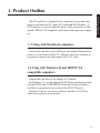
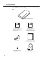
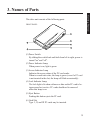
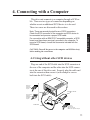
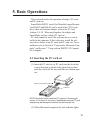
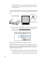
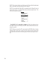
Preface
Precautions
Table of Contents
Product Outline
Accessories
Names of Parts
Connecting with a Computer
Basic Operations
Using the PC Card Drive
CD-10 with a Macintosh
Using the PC Card Drive CD-10
with IBM PC/AT Compatibles
E INSTRUCTION MANUAL
Troubleshooting
Specifications
Preface
The features of this product include:
• SCSI interface, the standard interface for personal computers.
• Of the standard PCMCIA/JEIDA cards, ATA cards and SRAM cards can be
used.
• Can be connected to Macintosh, IBM PC/AT compatible computers, NEC PC98 series, UNIX, VMS, AIX, etc.
• There is one slot ,which can be used for inserting type I, II and III PC cards.
* MS-DOS is the registered trademark of Microsoft.
* Apple and Macintosh are the registered trademarks of Apple Computer, Inc.
* IBM PC/AT is the trademark of International Business Machines Corporation.
* EZ-SCSI is the trademark of Adaptec, Inc.
* PhotoDeluxe is the registered trade mark of Adobe Systems, Inc.
* SmartMedia is the registered trademark of Toshiba Inc.
* Other company names and product names are the trademarks and registered trademarks of their
respective companies.
1. We have taken every necessary precaution to ensure the accuracy of this
product and this manual. However, we can not be held responsible for the results
of operation.
2. The product and the manual are subject to improvements without notice.
3. This manual may not be reproduced in whole or in part without our prior
permission.
1
Getting Started
Thank you very much for purchasing the Minolta PCMCIA Card
Drive CD-10.
The Minolta PCMCIA Card Drive CD-10 can be connected to
various makes of personal computers to read and write PC cards
(PCMCIA/JEIDA specifications) and PC card adapter sets like the
Minolta RM-2S/RM-4S SmartMedia™ image memory cards used
with the Minolta CA-1S PC card adapter. The data recorded on a PC
card with a digital still camera can be directly read into a personal
computer. Please read these instructions carefully before use.
Precautions
This symbol means "WARNING" and indicates caution should be used.
Please read and understand each warning message thoroughly before
operating this equipment. Failure to follow warning messages may
result in serious injury, fire, or equipment damage.
Safety Precautions and handling
Power cord
- Do not bend the power cord excessively or place heavy objects on
it. Damage to the cord may cause fire or electric shock.
- Do not pull the cord itself to unplug; always hold the plug and pull.
- Do not plug or unplug with wet hands.
- Unplug from the outlet when you are not using the unit for long
periods.
- Plug the power cord directly into a wall outlet whenever possible.
Use of extension cords and power dividers can cause malfunctions.
- Do not use an outlet to which large electrical appliances such as
air conditioners and copy machines are connected.
To prevent electric shock
Never remove the cabinet of this unit. Some components inside
operate at high voltages and can cause severe electric shock if
touched.
Keep objects and materials out of the unit
Make sure that no liquid is spilled or leaks into this unit and that
no metal or inflammable objects fall inside since these can cause
fire, shock, malfunctions, or accidents.
In case of accident or malfunction
If the unit makes unusual noises or begins smoking, or if a foreign object gets inside the unit, unplug the power cord from the
outlet and contact the store from which you purchased the unit or a
nearby service center.
2
Proper places for use and storage
- This unit is to be used at temperatures between +5°C and +40°C
and at relative humidities between 20% and 80% (no condensation).
- Do not use or store the unit in an excessively hot or cold place.
- Do not use or store the unit in a dusty place or in direct sunlight.
- Do not use or store the unit in a place subject to excessive vibration or in an unstable place.
- Do not place the unit close to a system which generates strong
magnetic fields(motor, transformer, television, loudspeaker, magnet etc.).
- Do not obstruct vents, it may cause the internal temperature to
rise. Do not stack the units. Do not use in a non ventilated area.
Precautions for connection
When connecting this unit to a personal computer or any other
equipment, always first turn off the main power of the equipment
to be connected.
Precautions for transportation
- Disconnect cables and remove the PC card before transporting
the unit.
- Use the cardboard box in which the unit was initially packed.
- This is a precision device. Do not subject to excessive shock or
vibration.
Maintenance of the cabinet
- Do not use thinner, benzene, insecticide and other volatile
substances to clean the cabinet.
- Clean the cabinet and front panel with a soft cloth. Remove dirt
with a soft cloth moistened with a small amount of neutral detergent diluted with water. Wipe dry after cleaning.
- Disconnect the power plug from the outlet before performing any
maintenance on the unit.
3
Getting Started
Power source
Use a standard domestic household power supply (100 to 240V,
50/60Hz).
FCC Radio Frequency Interference Warning
Notice for customers in U.S.A
This equipment generates and uses radio frequency energy, and if
not installed and used in strict accordance with the manufacturer’s
instructions, can cause interference to radio and television reception.
This equipment has been certified and found to comply with the
limits for a Class B computing device in accordance with the specifications in Subpart J of Part 15 of the FCC rules, which are designed
to provide reasonable protection against such interference in a commercial installation.
However, there is no guarantee that interference will not occur in a
particular installation. If this equipment does cause interference to
radio or television reception, which can be determined by turning the
equipment off and on, the user is encouraged to try to correct the interference by one or more of the following measures:
1. Reorient the receiving antenna.
2. Reorient the computer with respect to the receiver.
3. Move the computer further away from the receiver.
4. Plug the computer or receiver into a different outlet so computer
and receiver are on different branch power circuits.
5. Ensure that card mounting screws, attachment connector screws,
and ground wires are tightly secured.
If necessary, the user should consult with the dealer or an
experienced radio/television technician for additional suggestions.
The user might find the following booklet helpful, prepared by the
Federal Communications Commission: How to Identify and Resolve
Radio TV Interference Problems. It is available from the U.S.
Government Printing Office, Washington, DC 20492, Stock No.
004-000-00345-4 (FCC Part No. 15.838b)
Notice for customers in Canada
This apparatus complies with the Class B limits for radio noise
emissions set out in Radio Interference Regulations.
This mark cortifies this product meet the requirements of the
EU(European Union) concerning interference causing equipment regularions.
CE stands for Conformité Européemme (European Conformity).
4
PC Cards
All unformatted PC cards should be formatted in the camera with
which they are used.
When using the Minolta RD-175 digital camera to format cards,
erase all of the data on the card before formatting it.
PC Card Adapter Sets
In this manual, all of the examples are shown using the Minolta PC
CA-1S card adapter with the Minolta RM-2S/RM-4S SmartMedia
image memory card.
Digital Cameras
The Minolta PCMCIA Card Drive CD-10 is compatible with flash/
ATA, hard drives, and SRAM. However, all cards must be DOS formatted.
5
Getting Started
Most PC cards compatible with PCMCIA/JEIDA standard specifications (ATA cards and SRAM cards) can be used. A variety of products are compatible with the PCMCIA/JEIDA specification, but the
specifications are ambiguous and certain rules allow a large latitude.
As a result, some PC cards may not conform with the read/write
hardware and driver software. If you have questions about the compatibility of specific brands, please contact us with the card type,
manufacturer, and card specifications. Special driver requirements
may be necessary for Linear Flash, AIMS, and other PC cards. Before using a PC card, first read the instructions for the card.
TABLE OF CONTENTS
Preface
Precautions
1
2
TABLE OF CONTENTS
6
1. Product Outline
7
Using with Macintosh computers
Using with IBM PC/AT compatible computers
2. Accessories
8
3. Names of Parts
9
4. Connecting with a Computer
11
Using without other SCSI devices
Using with other SCSI devices
Setting the SCSI ID
Turning on the power
11
12
13
14
5. Basic Operations
Inserting the PC card
Removing the PC card
6. Using with a Macintosh
Functions of Mac-PC Manager Lite
Installation procedure for Mac-PC Manager Lite
7. Using with IBM PC/AT Compatible Computers
Replacing the ASPIDISK.SYS driver
8. Troubleshooting
Macintosh Systems
IBM PC/AT Systems
For more information
9. Specifications
6
7
7
15
15
17
19
19
20
21
23
24
24
25
26
27
1. Product Outline
1-1 Using with Macintosh computers
Connect the card drive to the SCSI port, the standard Macintosh interface. Use the enclosed MAC-PC Manager Lite driver software as
an option to mount removable media such as PC cards.
1-2 Using with Windows 95 and IBM PC/AT
compatible computers
Connect the card drive to the Adaptec SCSI board.
For Windows 3.1, use the Adaptec EZ-SCSI driver software provided
with the SCSI board. ASPIDISK.SYS (included in this package) is
available as an option for use as one of the EZ-SCSI drivers.
Windows 95 has its own driver software, therefore, EZ-SCSI or
other driver software is not needed.
7
Getting Started
This PC card drive is designed to be connected to a personal computer to read and write PC cards (ATA cards and SRAM cards). A
SCSI interface is used to enable the device to be connected to a Macintosh, IBM PC/AT compatible, and various other personal computers.
2. Accessories
LO
C
K
A
C
C
ES
S
PO
W
ER
The PCMCIA Card Drive CD-10 package contains the following
items:
PCMCIA Card Drive CD-10
8
Mac-PC Manager™ Lite
ASPIDISK floppy disk
Contains Mac-PC Manager Lite, a
software driver for connection with a
Macintosh computer.
Contains ASPIDISK.SYS, a
software driver for connection with
an IBM/PC compatible computer.
AC Adapter
PCMCIA Card Drive CD-10
User's Manual (this manual)
Screwdriver to change
SCSI ID address
SCSI Cable
(D-Sub25 pin to 50-pin Full-pitch)
3. Names of Parts
Getting Started
This drive unit consists of the following parts:
FRONT PANEL
1
2
6
3
4
5
(1) Power Switch
By sliding the switch back and forth from left to right, power is
turned "on" and "off".
(2) Power Indicator Lamp
When power is on, light is green.
(3) Access Indicator Lamp
Indicates the access status of the PC card reader.
When in a read/write state, the lamp is green (even if a PC card
is not inserted in the slot, the lamp will blink occasionally) .
(4) Lock Indicator Lamp
The lock light is lit when software or data on the PC card is being accessed or is active. PC cards should not be removed
when this lamp is on.
(5) Eject Button
Pushing this button ejects the PC card.
(6) Card Slot
Type I, II, and III PC cards may be inserted.
9
REAR PANEL
9
7
10
8
(7) Terminator Switch
When this switch is "on", the terminator is active. When this is the last
device on a SCSI chain, the switch should be set to "on" (for further
details see section 4 on "Connecting with a Computer").
(8) SCSI connector
SCSI cable is connected here (D-Sub25 pin).
(9) AC adapter plug
Plug in AC adapter here.
678
123
90
SCSI ID Switch
SWITCH 0 1 2 3 4 5 6 7 8 9
SCSI ID 0 1 2 3 4 5 6 7 0 1
45
(10) SCSI ID switch
Use this switch to set SCSI ID number. Take care not to set
the SCSI ID number to numbers already in use by the PC or
other peripheral devices.
10
4. Connecting with a Computer
This drive unit connects to a computer through a SCSI cable. There are two types of connection depending on
whether or not an additional SCSI device is to be used.
These two cases are discussed in this section.
Connecting
Note: There are several physical forms of SCSI connectors.
Check the SCSI connector of the computer and SCSI device to
be connected and procure a proper SCSI cable.
For connection with an IBM PC/AT compatible computer, a SCSI
board must have been previously mounted in the computer. To
mount a SCSI board, consult the documents included with the
SCSI board.
CAUTION: Turn off the power to the computer and SCSI device(s)
before making the connections.
4-1 Using without other SCSI devices
Plug one end of the SCSI cable into the SCSI connector at
the rear of the computer and the other into the SCSI connector at the rear of this drive unit. Securely plug the cable end
into the connector then secure it (with clamps or screws
built into the SCSI cable).
D-Sub25 pin
SCSI cable
for Macintosh
computer
Card Drive CD-10
50-pin full-pitch
SCSI cable
for IBM PC/AT
compatible
computer
SCSI cable
D-Sub25 pin
SCSI cable for
Macintosh computer
IBM PC/AT compatible computer
11
NOTE: The cable included in this package is a D-Sub25 to 50-pin full-pitch,
intended for use with most IBM PC/AT compatible computers. Macintosh
users may require a D-Sub25 to D-Sub25 SCSI cable, available at most
computer stores.
4-2 Using with other SCSI devices
Since the SCSI standard supports connection to one computer and
up to seven SCSI devices (including SCSI devices built into the
computer), you can use several CD-10 card drives in series or can
connect the CD-10 drive to other SCSI device(s).
Plug one end of the SCSI cable to the SCSI connector at the rear of
the computer and the other into the SCSI connector at the rear of this
drive unit. Securely plug the cable end into the connector then secure it (with clamps or screws built into the SCSI cable).
The order of the SCSI devices to be connected can be changed.
Card Drive CD-10
3
SCSI Cable
12
4-3 Setting the SCSI ID
Connecting
The SCSI ID is a unique number assigned to each SCSI device.
Therefore, two devices must not have the same ID number. The
SCSI ID is independent of the order of physical device connection.
Note that SCSI IDs may have been previously assigned to a disk
drive, CD-ROM drive, or other built-in devices in the computer. To
obtain this information, refer to the related computer and SCSI device manuals. Take care not to use the same ID number more than
once.
NOTE: Change the SCSI ID number after turning off the power to this
drive unit and computer. The new number will not become effective
while power is still supplied.
To set the SCSI ID
Change the value on the ID number display window by turning the
SCSI ID switch (use the enclosed screwdriver). If two devices have
the same SCSI ID, reassign all the ID numbers.
The initial default value “4” is assigned to this drive unit in the
plant before shipment.
For Macintosh computers
SCSI ID numbers 0 and 7 are used by the Macintosh hard drive
and system. SCSI ID number 3 is used by internal CD-ROM drives.
Therefore, SCSI ID numbers 2, 4, 5, and 6 are available for use with
this drive unit (unless already taken by another external SCSI deSCSI ID 7 is assigned to
SCSI ID 3 is assigned to
vice).
the internal CD-ROM drive.
the Macintosh system.
SCSI ID Switch
SWITCH 0 1 2 3 4 5 6 7 8 9
SCSI ID 0 1 2 3 4 5 6 7 0 1
SWITCH 0 1 2 3 4 5 6 7 8 9
SCSI ID
0 1 2 3 4 5 6 7 0 1
SCSI ID 0 is assigned
to the hard drive.
NOTE: SCSI ID number 3 is available when the Macintosh does not have
a built-in CD-ROM drive. For an external CD-ROM drive, SCSI IDs other
13
than 3 may be assigned.
The SCSI ID for the built-in hard disk drive and the computer cannot be
changed. Also, notice the SCSI IDs for Macintosh computers range from 0
to 7, the numbers on the SCSI switch are 0 through 9. If 8 and 9 on the
switch are selected, IDs 0 and 1 are assigned, respectively.
For IBM PC/AT compatible computers
SCSI IDs 0 and 1 may have been previously assigned to the builtin hard disk drive. Therefore, the values 2 through 6 are recommended as SCSI IDs for this drive unit. For details, consult the manuals
for EZ-SCSI and SCSI board.
Use SCSI IDs 2 through 6
SCSI ID Switch
SWITCH 0 1 2 3 4 5 6 7 8 9
SCSI ID 0 1 2 3 4 5 6 7 0 1
SWITCH 0 1 2 3 4 5 6 7 8 9
SCSI ID 0 1 2 3 4 5 6 7 0 1
SCSI IDs 0 and 1 are
assigned to the hard drive.
NOTE: The SCSI ID numbers range from 0 to 7, but the SCSI ID switch
numbers are 0 through 9. If 8 and 9 on the switch are selected, IDs 0 and
1 are assigned, respectively.
4-4 Turning on the power
To connect the AC adapter, plug the end of the power cord included in the package into the power connector on the rear of this drive
unit, then plug the other end into the AC outlet. The cord should be
firmly and securely connected and should be grounded before use.
Turn on the power for this drive unit then turn on the computer.
When the computer is ready, install the software driver in accordance with Section 6 “Using with a Macintosh computer” and Section 7 “Using with an IBM PC/AT compatible computer”.
NOTE: Use only the AC adapter included in this package. The AC adapter
included in this package is not meant for use with equipment other than
the CD-10 drive.
14
5. Basic Operations
Operating
This section describes the operation relating to PC cards
and PC card sets.
SmartMedia SSFDC cards (like Minolta's Image Memory
Card RM-2S and RM-4S) can be used in the CD-10 card
drive when used with an adapter, such as the PC Card
Adapter CA-1S. When used together, the adapter and
SmartMedia card are called a PC card set.
PC cards cannot be used if the software driver is not installed in the computer. If this is the case, install the software driver before using PC cards and PC card sets. For installation, refer to Section 6 “Using with a Macintosh Computer” and Section 7 “Using with an IBM PC/AT Compatible Computer”.
5-1 Inserting the PC card set
(1) Insert the PC card set (or PC card) into the slot in the
correct direction as shown in the figure below, then
push the card in all the way until the eject button pops
out.
Surface (side with the symbol
)
Connector
NOTE: Be careful not to insert the PC card set in the wrong direction. If it is forced in, the slot or SmartMedia card and PC card
adapter may be damaged or data on the card may be lost.
(2) With a Macintosh computer, the lock indicator lights
15
first and then the PC card icon appears on the monitor. This is
the “mounted” state, which enables read and write operations
for the PC card set.
The time required between card insertion and mounting depends on
the card. Usually, the PC card set can be mounted within several seconds.
The lock indicator lights
when the card is mounted
PC card icon is displayed
(3) If the PC card or SmartMedia card is not formatted, the following box appears. Do not click on "Initialize". Unformatted
cards should always be formatted in the camera.
NOTE: Minolta SmartMedia cards are already formatted.
IMPORTANT: When using the Minolta RD-175 digital camera, erase all
data on the card first, then reformat the card in the camera. Failure to use
this procedure may cause errors. Please read your RD-175 software instruction manual for more details.
(4) For IBM PC/AT compatible computers, the lock indicator does
not usually light even after a PC card is inserted. For a Macintosh computer, wait for several seconds to access the PC card.
16
5-2 Removing the PC card set
Make sure that the access indicator and lock indicator are not lit,
then press the eject button to release the PC card set.
access indicator
lock indicator
Operating
When the access indicator is lit
In this case, the data is being read or written. Wait until the operations complete; then remove the card set. Removing a PC card or PC
card set during access operations will cause the data to be lost.
When the lock indicator is lit
The lock indicator differs between Macintosh and IBM PC/AT
platforms. Therefore, this section is divided into two parts;
Macintosh and IBM PC/AT.
For Macintosh: The lock indicator lights when the PC card set is
mounted. Dragging the PC card icon and dropping it onto the trash
icon ejects the PC card set, deletes the PC card icon and turns off the
lock indicator on this drive unit.
Do not remove a mounted PC card set. If removed, the following
message appears on the screen. Put the card set back into the slot.
Removing a mounted PC card or PC card set may damage the data stored
on it.
17
NOTE: The access indicator may flash on and off even after the eject operation. In this case, you can remove the PC card set.
NOTE: Do not select the “Eject Disk” command from the “Special” menu to
remove the card set. The CD-10 drive does not have an eject motor. The
disk must be ejected manually.
For IBM PC/AT compatible computers: The lock indicator does
not light in most cases. Remove the PC card set when the access indicator is not lit.
NOTE: When you mount the PC card set with the EZ-SCSI utility, the lock
indicator lights. In this case, unmount the PC card set with the same utility,
then make sure that the lock indicator goes off before removing the card
set.
18
6. Using with a Macintosh
6-1 Functions of Mac-PC Manager Lite
Mac-PC Manager Lite is a software driver that automatically mounts Macintosh formatted and DOS (MS-DOS/V,
PC-DOS/V) formatted PC cards and floppy disks. Mac-PC
Manager Lite provides the following functions:
Mac PC-Manager™ Lite
- Automatically mounts the Macintoshformatted or DOS-formatted PC cards.
- Links JPEG image files to Adobe
PhotoDeluxe™.
Macintosh
NOTE:
• The DOS format is used by IBM PC/AT compatible computers
and Minolta’s digital still cameras. The files stored on a DOS-formatted PC card are DOS files.
• Mac-PC Manager Lite is able to read DOS text files. However,
DOS uses CR (carriage return) as well as LF (line field) while
Macintosh only uses CR. When using Mac-PC Manager Lite with
DOS text files LF will appear as a blank space.
• Windows 95 allows 255 characters to be used for a file name.
Macintosh file names are limited to 31 characters. When using
Mac-PC Manager Lite to mount a DOS file with more than 31
characters the title will appear reduced. See the example below.
WIN 95: AABBCCDDEEFFGGHHIIJJKKLLMMNNOOPPQQ.TXT
MAC:
AABBCCDDEEFFGGHHIIJJKK"HMR.TXT
19
6-2 Installation procedure for Mac-PC Manager Lite
Mac-PC Manager Lite is an extension and therefore it must be copied into the extensions folder on the hard disk. System 7.1 or a later
version is needed to run this extension.
(1) Insert the floppy disk marked "Mac-PC Manager™ Lite".
(2) Double click on the disk icon. The icon “Mac-PC Manager™
Lite” is displayed. Drag this Mac-PC Manager icon onto the
system folder.
(3) The following message appears asking to drop the Mac-PC
Manager Lite icon into the extensions folder. Click on “OK”.
You have now installed your Mac-PC Manager in the extensions folder.
(4) Make sure that Mac-PC Manager Lite is copied into the extensions folder then restart the computer.
20
7. Using IBM PC/AT
Compatible Computers
Windows 95
The PCMCIA Card Drive CD-10 connects with the
Adaptec SCSI board. Windows 95 includes its own driver
software, therefore it is not necessary to install additional
driver software. However, when working in DOS mode,
additional driver software is needed - please refer to the following section, "Windows 3.1 and DOS".
Environment
The following computing environment is required:
• SCSI board:
AHA-1510B, AHA-1520B,
AHA-1540CP, AHA-1030P,
AHA-2940
IBM/Windows
PC Cards
Minolta image memory cards are pre-formatted. Unformatted cards should always be formatted in the camera.
NOTE:
• Although it is not recommended, if it is necessary to format PC
cards in the computer, use the AFDISK format.
• IMPORTANT: When using the Minolta RD-175 digital camera
erase all data on the card first, then format the card in the camera. Failure to use this procedure may cause errors. A PC card
that is used with both the RD-175 and the CD-10 should always
be formatted in the camera to avoid errors.
• When using the PC Card Adapter Set disable BIOS on the SCSI
board.
21
Windows 3.1 and DOS
The PCMCIA Card Drive CD-10 connects to Adaptec’s
SCSI board. It also uses Adaptec’s software driver EZ-SCSI.
This section assumes that Adaptec’s SCSI board and EZSCSI software are installed. For installation of the SCSI
board and EZ-SCSI, consult the manuals for those items.
When connecting the CD-10 drive to the computer with
EZ-SCSI installed, the EZ-SCSI software should be reinstalled after connection.
Applicable environment
The CD-10 drive can be used in the following environment:
- SCSI board :
AHA-1542CF
- Software driver:
EZ-SCSI V.3.04
- Operating system: MS-DOS 6.20
- Windows:
Ver. 3.1
Checking the EZ-SCSI driver
(1) Check the directory in which the EZ-SCSI software is
installed. In general, EZ-SCSI is installed in the “SCSI”
directory. In this directory, the following two files must
be stored: ASPIxDOS.SYS and ASPIDISK.SYS
CAUTION: EZ-SCSI may be installed in directories with names
other than “SCSI”. In the directory where EZ-SCSI is installed,
there are usually various utility files as well as ASPIxDOS.SYS and
ASPIDISK.SYS.
(2) When EZ-SCSI is properly installed, the CONFIG.SYS
file must contain the following two lines:
DEVICE=C: SCSI ASPIxDOS.SYS /D
DEVICE=C: SCSI ASPIDISK.SYS /D
* ASPIxDOS.SYS, the ASPI DOS manager, depends
on the SCSI board. See following Note.
22
Note: The following SCSI boards and ASPI managers can be
used by the CD-10 drive with IBM PC/AT compatible computers:
ASPI Manager:
SCSI board:
ASPI2DOS.SYS AHA-1510A, AHA-1522A, APA-1460
ASPI4DOS.SYS AHA-1542CF
ASP7DOS.SYS AHA-2742-AT, AHA-2840A
ASPI8DOS.SYS AHA-2940
SCSI boards which use the AIC-7970 SCSI protocol chip
in standard mode.
The contents of the CONFIG.SYS file are as follows. Use
this for your installation.
(AHA-1542CF, EZ-SCSI V3.04, MS-DOS 6.20, and Windows 3.1)
DEVICE=C:\SCSI\ASPI4DOS.SYS /D
DEVICE=C:\SCSI\ASPIDISK.SYS /D
DEVICE=C:\DOS\SETVER.EXE
DEVICE=C:\DOS\HIMEM.SYS
DOS=HIGH
DEVICE=C:\DOS\EMM386.EXE
FILES=30
STACKS=9,256
The attached ASPIDISK floppy disk stores the
ASPIDISK.SYS driver, which can read the data recorded on
a PC card. Copy this file into the directory in which EZSCSI is installed.
(1) Insert the attached ASPIDISK floppy disk.
(2) Copy the ASPIDISK.SYS file stored in the ASPIDISK
floppy disk into the directory in which EZ-SCSI is installed.
(3) Remove the ASPIDISK floppy disk then restart the
computer.
23
IBM/Windows
To replace the ASPIDISK.SYS driver
8. Troubleshooting
Macintosh Systems
Symptom
The power will not
turn on.
Cause
The power is not connected to an outlet or
computer.
Nonstandard SCSI cable is used.
The Macintosh computer hangs up at
The SCSI cable is too long.
startup.
Corrective Measure
Insert the power plug securely into the
outlet or computer.
Use a standard SCSI cable.
Use a standard SCSI cable (6m or
shorter).
The CD-10 drive and other SCSI devices
are not properly connected.
Change the cable connections.
The terminator is not activated.
Activate terminator.
The same SCSI ID is assigned to more than Turn off the power to the SCSI device
then change the SCSI ID.
one SCSI device.
The CD-10 drive has the same SCSI ID as
another SCSI device.
Turn off the power to the SCSI device
then change its SCSI ID
The SCSI cables are not properly
connected.
Change the cable connections.
The PC card cannot The terminator is not activated.
be mounted (no icon
is displayed).
Mac-PC Manager Lite is not installed.
Activate terminator.
Install Mac-PC Manager Lite in the
system folder.
Disable or delete the suspect extended
Mac-PC Manager Lite is in contention with functions, or change their names and
other control panels or extended functions. the startup activation order.
The card is not properly inserted.
24
Insert the card properly.
IBM PC/AT Systems
Symptom
The power will
not turn on.
Cause
The power is not connected to an outlet or
computer.
Nonstandard SCSI cable is used.
The computer
hangs up at star- The SCSI cable is too long.
tup.
Corrective Measure
Insert the power plug securely in an outlet
or computer.
Use a standard SCSI cable.
Use a standard SCSI cable (6m or less in
length).
The settings for the SCSI board are not ap- Revise the settings according to the SCSI
propriate.
board manual.
The PC card
cannot be
recognized.
Loose connection in the SCSI connector.
Plug in the SCSI connector again.
The terminator is not activated.
Activate the terminator.
The same SCSI ID is assigned to another
SCSI device.
Power off all the devices then change the
SCSI ID.
A terminator is included in another hard
disk in a daisy chain connection.
Remove the terminator or deactivate the
terminator on the CD-10
EZ-SCSI is not installed.
Install EZ-SCSI according to the EZ- SCSI
manual. Check the CONFIG.SYS file for
the proper setting.
ASPIDISK is not installed.
Install ASPIDISK included in the attached
floppy disk.
The card is not properly inserted.
Insert the card properly.
Troubleshooting
25
For more information
For questions regarding installation and PCMCIA card
compatibility, please contact your dealer or a Minolta Service Facility. Be sure to include the following information
in your correspondence:
• The make and model of your computer.
• System software and version number.
• Information on any other connected SCSI devices.
• The symptoms of the problem the computer is having.
• Messages that appear on the screen with the problem.
• The frequency of occurrence of the problem.
• Your name, address, and telephone or fax number.
• PCMCIA card type, manufacturer, and specifications.
Minolta Co., Ltd.
3-13, 2-Chome, Azuchi-Machi, Chuo-Ku, Osaka 541, Japan
Minolta GmbH
Minolta France S.A.
Minolta (UK) Limited
Minolta Austria Ges. m.b.H.
Minolta Camera Benelux B.V.
Belgium Branch
Minolta (Schweiz) AG
Minolta Svenska AB
Finland Branch
Minolta Portugal Limitada
Minolta Corporation
Head Office
Los Angeles Branch
Minolta Hong Kong Limited
Minolta Singapore (Pte) Ltd.
26
Kurt-Fischer-Strasse 50, D-22923 Ahrensburg, Germany
365 Route de Saint-Germain, F-78420 Carrieres-Sur-Seine,
France
Rooksley Park, Precedent Drive, Rooksley, Milton Keynes,
MK13 8HF, England
Amalienstrasse 59-61, A-1131 Wien, Austria
Zonnebaan 39, P.O. Box 6000, NL-3600 HA Maarssen, The
Netherlands
Kontichsesteenweg 38, B-2630 Aartselaar, Belgium
Riedstrasse 6 CH-8953 Dietikon, Switzerland
P.O. Box 9058, Albygatan 114, S-17109 Solna, Sweden
Niittykatu 6 PL 37 SF-02201 Espoo, Finland
Rua Afonso Lopes Vieira 55-B P-1700 Lisboa, Portugal
101 Williams Drive, Ramsey, New Jersey 07446, U.S.A.
11150 Hope Street Cypress, CA 90630, U.S.A.
Room 208, 2/F, Eastern Center, 1065 King's Road, Quarry Bay,
Hong Kong
10, Teban Gardens Crescent, Singapore 608923
9. Specifications
Card type:
ATA and SRAM cards that comply with PCMCIA PC
Card Standard Release 2.1/JEIDA PC Card Guideline Ver.
4.2, and PC Card ATA Release 1.01
PC card slot:
1 Type I, II or III
Host interface:
SCSI-2
SCSI connector:
D-Sub25
Transfer rate: 3MB/sec (for asynchronous transfer)
Power requirements:
AC 100V to 120V, 50/60 HZ CD-10 STD
AC 100V to 240V, 50/60 HZ CD-10 UNIV
Power consumption:
0.2A
Dimensions: 77 (W) x 130 (D) x 23 (H) mm
(not including rubber protrusions and connectors)
Specifications
Weight:
Approx. 150 Grams
Operating temperature and humidity:
Temperature: +5°C to +40°C
Humidity: 20% to 80% (with no condensation)
27
9222-2755-91 (9610-A610)
28
Minolta Co., Ltd.