1
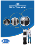
VERTX
SERVICE MANUAL
iCR VERTX – Service Manual
Foreword
Proprietary Notice and Disclaimer
The information herein disclosed is the property of iCRco., Inc. Information in this document is subject to change without notice and does not represent a commitment by iCRco to
incorporate changes or improvements in units previously sold or shipped.
No part of this document may be reproduced or transmitted in any form, electronic
or mechanical, including photocopying and recording, for any purpose other than the
purchaser’s own use without the express written permission of iCRco.
Copyright
c iCRco Inc. 2003 - 2010
Copyright All rights reserved.
Trademarks
R iCR 1000,
R iCR 1000 Dual,
R iCR 2600,
R iCR 2600 Dual,
R iCR 2600SF,
R iCR
iCR 2600,
R
R
R
R
R
R
Vet, iCR CR Vet Dual, iCR Mobile, iCR 1-D, iCR Chiro, iCR Chiro Dual, iCR
R iCR 3600SF,
R iCR VERTX,iDR
R
R
,www.icrcompany.com
3600,
and QPC XSCAN32 are
the trademarks of iCRco. All other trademarks are the property of their respective owners,
and are hereby acknowledged.
Terms
Any one of the following iCR products will be referred to as the “CR unit” throughout
R iCR 1000 Dual,
R iCR 2600,
R iCR 2600 Dual,
R iCR 2600SF,
R
this document: iCR 1000,
R iCR Vet,
R iCR Vet Dual,
R iCR Mobile,
R iCR 1-D,
R iCR Chiro,
R iCR Chiro
iCR 3600,
R iCR VERTX
R Any one of the following iCR products will be referred to as “iCR
Dual
R iCR 2600 Dual,
R iCR Vet Dual,
R
dual unit” throughout this document: iCR 1000 Dual,
R Any one of the following iCR products will be referred to as “iCR desktop
iCR Chiro Dual
R The iDRwill
R
unit” throughout this document: iCR VERTX.
be referred to as the “DR
unit” throughout this document.
c
2007-2009
Confidential and Proprietary
Property of iCRco, Inc.
i of 76
Document # VTX-DOD-02A Rev B
January 8, 2010
iCR VERTX – Service Manual
Contact Information
iCRco., Inc.
Address:
Phone:
Fax:
Email:
Web:
USA
2580 West 237th Street, Torrance, CA, 90505
+1.310.921.9559
+1.310.542.7236
[email protected]
http://www.icrcompany.com
iCRco., Inc.
Address:
Phone:
Email:
Web:
Europe
31a Ridlerstrasse, 80339 Munich, Germany
+49.89.2555.757.150
[email protected]
http://www.icrcompany.com
VertX Information
Please Enter the details of the VertX system here:
Serial Number:
Date Purchased:
Interface Type:
USB 2.0
c
2007-2009
Confidential and Proprietary
Property of iCRco, Inc.
ii of 76
Document # VTX-DOD-02A Rev B
January 8, 2010
iCR VERTX – Service Manual
Safety Information
Read and understand the installation and operating instructions before applying power to
the VertX.
CAUTION
INPUT: 100-240VAC
3A 50-60Hz
CAUTION: FOR CONTINUED
PROTECTION AGAINST RISK OF FIRE,
REPLACE ONLY WITH SAME TYPE AND
RATING OF FUSE.
FUSE
3A SLOW BLOW, 250V
CAUTION
CAUTION: TO REDUCE THE RISK OF
ELECTRONIC SHOCK, DO NOT REMOVE
COVER. NO USER SERVICEABLE PARTS
INSIDE. REFER SERVICING TO QUALIFIED
SERVICE PERSONNEL.
DANGER
Invisible laser
radiation when open.
AVOID EXPOSURE
TO BEAM.
Class 3b laser product.
(IEC 825-1)
Conventions
! DANGER A DANGER indicates an imminently hazardous situation which, if not
avoided, will result in death or serious injury. This signal word is to be limited to the most
extreme situations.
! WARNING A WARNING indicates a potentially hazardous situation which, if not
avoided, could result in death or serious injury.
! CAUTION A CAUTION indicates a potentially hazardous situation which, if not
avoided, may result in minor or moderate injury. It may also be used to alert against
unsafe practices.
Note A NOTE indicates important information that helps you make better use of your
VertX and Software.
Notice A NOTICE indicates either potential damage to hardware or loss of data and tells
you how to avoid the problem.
Laser Safety
!
CAUTION This equipment employs a laser. Laser radiation may be present if the VertX
is operated without the covers. Avoid the laser beam. Direct exposure to laser light must
be avoided.
The VertX incorporates a Red ≥ 80mw high-power solid-state laser diode. The VertX covers
c
2007-2009
Confidential and Proprietary
Property of iCRco, Inc.
iii of 76
Document # VTX-DOD-02A Rev B
January 8, 2010
iCR VERTX – Service Manual
protect the service person from direct exposure to laser light. These covers will protect
a user/service person only if they are properly installed. Covers must be removed and
replaced by properly trained service personnel. Contact iCRco if there are any issues with
the covers being damaged or replacement covers are needed.
Electrical Hazards
!
WARNING This equipment is operated with hazardous voltages which can shock, burn,
or cause death.
Notice The VertX must be connected to a uninterruptible power supply (UPS). Failure to
use a (UPS) will void the warranty.
The equipment must be serviced by properly trained technicians certified by iCRco, Inc. Do
not connect the VertX with a damaged or sub-standard power cable. Do not use an extension
cord with this device. The VertX should be properly grounded and power connections
inspected to ensure safe operation. Use at least a 1300VA (780W) uninterruptible power
supply (UPS) with this device, as it is sensitive to variations in power.
Malfunctioning Equipment
If any iCRco product shows signs of malfunction, discontinue the use of the product
immediately and contact Technical Support at 310-921-9559.
FCC Notification
This equipment generates, uses, and can radiate radio frequency energy, and if not installed
properly, can cause interference with radio communications.
Mammography Use
The VertX is not intended for Mammography use.
c
2007-2009
Confidential and Proprietary
Property of iCRco, Inc.
iv of 76
Document # VTX-DOD-02A Rev B
January 8, 2010
iCR VERTX – Service Manual
Guidance and Manufacture’s declaration – Electromagnetic Emissions & Immunity
Table 1: Electromagnetic Emissions
Guidance and manufactures’ declaration – electromagnetic emissions
The VertX is intended for use in the electromagnetic environment specified
below. The customer or the user of the VertX should assure that it is used in
such an environment.
Emissions test Compliance
Electromagnetic environment – guidance
RF emissions
Group 1
The VertX uses RF energy only for its internal
CISPR 11
function. Therefore, its RF emissions are very low
and are not likely to cause any interference in
nearby electronic equipment.
RF emissions
Class B
The VertX is suitable for use in all establishments,
including domestic and those directly to the
CISPR 11
Harmonic
Class B
public low voltage pwoer supply network that
emissions IEC
supplies buildings used for domestic purposes.
61000-3-2
Voltage fluctu- Complies
ations/flicker
emissions IEC
61000-3-3
Table 2: Electromagnetic Immunity
Immunity
Test
Electrostatic
discharge
(ESD) IEC
61000-4-2
IEC 60601 Test
Level
±(2, 4, 6) kV
Contact
Compliance
Level
±(2, 4, 6) kV
Contact
±(2, 4, 8) kV
air
±2 kV for
power supply
lines
±(2, 4, 8) kV
air
±2 kV for
power supply
lines
±1kV for
input/output
lines
continued on next page. . .
±1kV for
input/output
lines
Electrical
fast transient/burst
IEC
61000-4-4
c
2007-2009
Confidential and Proprietary
Property of iCRco, Inc.
v of 76
Electromagnetic Environment –
Guidance
Floors should be wood, concrete
or ceramic tile. If floors are
covered with synthetic material,
the relative humidity should be at
least 30%.
Mains power quality should be
that of a typical commercial or
hospital environment.
Document # VTX-DOD-02A Rev B
January 8, 2010
iCR VERTX – Service Manual
Table 2 continued. . .
Immunity IEC 60601 Test
Test
Level
Surge IEC
±1 kV
61000-4-5
differential
mode
Voltage
dips, short
interruptions and
voltage
variations
on power
supply
input lines
IEC
61000-4-11
Compliance
Level
±1 kV
differential
mode
±2 kV
common mode
<5% UT
(>95% dip in
UT ) for 0.5
cycle.
±2 kV
common mode
<5% UT
(>95% dip in
UT ) for 0.5
cycle.
40% UT (60%
dip in UT ) for
5 cycles.
40% UT (60%
dip in UT ) for
5 cycles.
70% UT (30%
dip in UT ) for
25 cycles.
70% UT (30%
dip in UT ) for
25 cycles.
<5% UT
(>95% dip in
UT ) for 5 sec.
3A/m
<5% UT
(>95% dip in
UT ) for 5 sec.
3A/m
Electromagnetic Environment –
Guidance
Mains power quality should be
that of a typical commercial or
hospital environment.
Mains power quality should be
that of a typical commercial or
hospital environment. If the user
of the VertX requires continued
operation during power mains
interruptions, it is recommended
that the VertX be powered from
an uninterruptible pwoer supply
or a battery.
Power
Power frequency magnetic fields
frequency
should be at levels characteristic
(50/60Hz)
of a typical location in a typical
magnetic
commercial or hospital
field IEC
environment.
61000-4-8
NOTE: UT is the a.c. mains voltage prior to application of the test level.
continued on next page. . .
c
2007-2009
Confidential and Proprietary
Property of iCRco, Inc.
vi of 76
Document # VTX-DOD-02A Rev B
January 8, 2010
iCR VERTX – Service Manual
Table 2 continued. . .
Immunity IEC 60601 Test
Test
Level
Conducted 3Vrms 150 kHz
RF IEC
to 80 MHz
61000-4-6
3 V/m 80 MHz
to 2.5 GHz
Radiated
RF IEC
61000-4-3
Compliance
Level
3Vrms
3 V/m
Electromagnetic Environment –
Guidance
Portable and mobile RF
communications equipment
should be used no closer to any
part of the VertX, including cables,
than the recommended separation
distance calculated from the
equation applicable to the
frequency of the transmitter.
Recommended separations
distance
√
d = 1.2√P
d = 1.2√P 80 MHz to 800 MHz
d = 2.3 P 800 MHz to 2.5 GHz
where P is the maximum output
power rating of the transmitter in
watts (W) according to the
transmitter manufacturer and d is
the recommended separation
distance in meters (m).
Field strengths from fixed RF
transmitters as determined by an
electromagnetic site surveya ,
should be less than the
compliance level in each
frequency rangeb .
Interference may occur in the
vicinity of equipment marked
with the following symbol:
NOTE 1: At 80 MHz and 800 MHz, the higher frequency range applies.
NOTE 2: These guidelines may not apply in all situations. Electromagnetic
propagation is affected by absorption and reflections from structures, objects
and people.
continued on next page. . .
c
2007-2009
Confidential and Proprietary
Property of iCRco, Inc.
vii of 76
Document # VTX-DOD-02A Rev B
January 8, 2010
iCR VERTX – Service Manual
Table 2 continued. . .
Immunity IEC 60601 Test Compliance
Electromagnetic Environment –
Test
Level
Level
Guidance
a Field strengths from fixed transmitters, such as base stations for radio
(cellular/cordless) telephones and land mobile radios, amateur radio, AM
and FM radio broadcast and TV broadcast cannot be predicted theoretically
with accuracy. To assess the electromagnetic environment due to fixed RF
transmitters, an electromagnetic site survey should be considered. If the
measured field strength in the location where the VertX is used exceeds the
applicable RF compliance levels above, the VertX should be observed to
verify normal operation. If abnormal performance is observed, additional
measures may be necessary, such as reorienting or relocating the VertX.
b Over the frequency range 150 kHz to 80 MHz, field strengths should be
less than 3 V/m.
iCRco Warranty
iCRco, Inc. (“iCRco”) values your business and always strives to provide high quality
products and services. All iCRco products are provided with an initial warranty so the
hardware and software are covered from the date of purchase. This limited warranty
solely applies to new products manufactured by or for iCRco and originally purchased
from iCRco or an authorized dealer of iCRco products for your own use. In addition, an
extended warranty is available for most new and recently purchased iCRco products for an
additional charge.
Hardware Limited Warranty
iCRco warrants its hardware products to be free of defects in materials and workmanship
for a period of one (1) year from the date of original shipment from iCRco subject to the
limitations set forth herein. If a product proves to be defective in material or workmanship
during the warranty period, iCRco will, at its sole option, repair or replace the product
with a similar product. Repaired and replacement products may be or include refurbished
or remanufactured parts. Any replacement item assumes the remaining warranty period of
the original product. iCRco provides no warranty for any third party hardware or software
included with any product or later acquired.
Software Limited Warranty/Support
iCRco warrants that its QPC XSCAN32, Captera, and/or ClarityPACS software originally
provided with any product will substantially conform to iCRco’s specifications and that
the media, not including hard drives, on which the software is furnished will be free from
c
2007-2009
Confidential and Proprietary
Property of iCRco, Inc.
viii of 76
Document # VTX-DOD-02A Rev B
January 8, 2010
iCR VERTX – Service Manual
defects in materials and workmanship under normal use for a period of one (1) year from
the date of original shipment from iCRco. iCRco’s sole obligation under this warranty is
limited to making reasonable efforts to ensure such conformity and to supply the consumer
with a corrected version of the software as soon as it is practical after the consumer has
notified iCRco of any non conformity. iCRco does not warrant that the operation of any
software will be uninterrupted, glitch or error free or that functions contained in the
software will operate in the combinations which may be selected for use by the user or
meet the user’s requirements. This limited software warranty will be void if the software is
modified without the written approval of iCRco or is used outside of the recommended
parameters or equipment. iCRco does not provide any warranty or support for any other
software.
iCRco agrees to provide one (1) year of telephonic and/or e-mail based support for QPC
XSCAN32, Captera, and/or ClarityPACS software originally provided with any new iCRco
product from the date of original shipment from iCRco. All software support shall be
limited to making reasonable efforts to resolve iCRco software issues and shall be limited
to iCRco’s regular business hours. In addition, iCRco will provide revisions and upgrades
to its software upon request (when available) during the first year after the software was
originally shipped from the iCRco factory. The initial support period will include support
via remote login software (GoToMeeting), only if the customer has access to the Internet
from that PC and only if the customer agrees iCRco shall have no liability in connection
with its support efforts. Remote login software allows iCRco technical support to remotely
access the customer’s PC via the Internet for the purposes of rendering technical support.
Please note that this warranty, including software support, does not include computer
hardware, third party software or operating system or network issues, which are outside
the control of iCRco.
Warranty Product Technical Requirements
iCRco requires that all DR, CR, Scanner and/or products requiring PCs be fitted and
installed with a 1500VA (1500W) uninterruptible power supply (“UPS”). iCRco recommends
the APC 1000 specification UPS or equivalent. For warranty evaluation and service, iCRco
requires the customer to provide an Internet connection (DSL or Dial-up) or the minimum
of a phone line accessible by an extension cord to the product enabling iCRco technicians to
perform remote diagnostics on installed equipment. In addition, each iCRco product must
be installed, maintained and operated in accordance with the respective product manual.
Failure to comply with these requirements will result in a voided warranty claim.
Requesting Warranty Service
For information on obtaining warranty service, call iCRco’s customer support at (310)9219559. In order to evaluate a warranty service request, iCRco requires the following information: the iCRco serial number of the product, a detailed description of the problem,
customer name and contact information; product location and operating conditions; a copy
c
2007-2009
Confidential and Proprietary
Property of iCRco, Inc.
ix of 76
Document # VTX-DOD-02A Rev B
January 8, 2010
iCR VERTX – Service Manual
of the purchase documents, and sufficient information and authorization, including a liability release as to any loss of data (that should always be backed up), software or network
injury, or downtime, allowing iCRco technicians remote access to the product. Product may
not be returned to iCRco without first obtaining a Return Material Authorization (“RMA”)
number from iCRco. Prior to providing an RMA, iCRco may require remote access to the
product. If iCRco determines that the product may be defective, is under warranty and
necessitates a return to iCRco for service, an RMA number and instructions for return of
the product will be given. iCRco is not responsible for any unauthorized returned product,
i.e. one for which an RMA number has not been issued by iCRco.
Warranty service requires all authorized returns be shipped to the iCRco factory prepaid
and insured. All such authorized returns are the customer’s responsibility. For products
sold and located within the United States, iCRco will pay for return shipping.
Products being returned are only to be shipped in iCRco approved shipping containers.
The original box and packaging materials are approved and should be kept for moving
and/or shipping the product. Approved packaging my also be purchased from iCRco for
an additional charge. iCRco shall have no liability nor responsibility for warranty service
to any product that is not shipped in an iCRco approved shipping container or that is
damaged from incorrect packaging or damaged during shipping.
Additional Warranty Limitations and Extent of Warranty
This warranty does not apply if the product has been damaged by accident, misuse or
abuse. In addition, warranty service does not include the repair of failures or defects caused
by: unauthorized attachments to any iCRco product, unsuitable physical or operating
environment, maintenance or repair by anyone other than iCRco or the iCRco authorized
dealer that sold the product, operation of a product beyond its duty cycle, use of the
product outside of its specifications, the use of supplies, parts, materials, software, or
interfaces not furnished, authorized or recommended by iCRco. If the product, including
any software has been opened, tampered with, modified or altered in any way without
written authorization by iCRco, the warranty will no longer apply.
This warranty applies only to products manufactured by, or for, iCRco, and that can be
identified by an “iCRco” serial number as originally affixed to the product. Any modification to the iCRco serial number tag or its attachment to the product shall immediately void
the warranty.
This warranty is non-transferable and subsequent owners must contact iCRco to establish
if the equipment is eligible for an extended warranty.
THERE ARE NO WARRANTIES, EXPRESS OR IMPLIED, WITH RESPECT TO ANY iCRco
PRODUCT OTHER THAN AS SPECIFICALLY SET FORTH HEREIN, AND iCRco SPECIFICALLY DISCLAIMS ANY IMPLIED WARRANTIES OR CONDITIONS OF MERCHANT
ABILITY, FITNESS FOR A PARTICULAR PURPOSE, AND SATISFACTORY QUALITY.
ANY WARRANTIES THAT MAY NOT BE DISCLAIMED UNDER APPLICABLE LAW
c
2007-2009
Confidential and Proprietary
Property of iCRco, Inc.
x of 76
Document # VTX-DOD-02A Rev B
January 8, 2010
iCR VERTX – Service Manual
ARE LIMITED IN DURATION TO THE INITIAL WARRANTY PERIOD AND NO WARRANTIES, EXPRESS OR IMPLIED, WILL APPLY AFTER THIS PERIOD. ALL INFORMATION, SPECIFICATIONS, PRICES, AND SERVICES ARE SUBJECT TO CHANGE AT ANY
TIME WITHOUT NOTICE.
Limitation of Remedies and Liability/Exclusion of Damages
The exclusive remedy for any defective product is limited to the repair or replacement of
the defective product. iCRco shall have a reasonable time after determining that a defective
product exists to repair or replace a defective product. iCRco’s entire liability for any
product is limited to the actual purchase price for the product. This limitation applies even
if iCRco cannot or does not repair or replace any defective product.
IN NO EVENT WILL iCRco BE LIABLE FOR ANY GENERAL, SPECIAL, CONSEQUENTIAL OR INCIDENTAL DAMAGES, including but not limited to, damages related to
the loss of use, loss of recorded product, the installation of replacement product, or any
inspection, testing, or redesign caused by any defect or by the repair or replacement of
any product arising from a defect in any product. This exclusion of damages applies even
if the customer advises iCRco or an iCRco dealer of the possiblity of such damages. This
limitation of remedies also applies to claims against any suppliers or dealers of iCRco. iCRco and its
suppliers’ and dealers’ limitations of remedies are not cumulative. Such suppliers and dealers are
intended beneficiaries of this limitation. iCRco is not liable for any claim by or against the customer
arising from a third party claim.
Revision History
Revision
A
B
C
Author
MS
MS
MS
Date
2009-02-06
2010-01-08
2010-03-22
c
2007-2009
Confidential and Proprietary
Property of iCRco, Inc.
Notes
Initial Release
Updated layout
Updated safety information
xi of 76
Document # VTX-DOD-02A Rev B
January 8, 2010
iCR VERTX – Service Manual
Contents
Foreword
i
Contact Information . . . . . . . . . . . . . . . . . . . . . . . . . . . . . . . . . . .
ii
Safety Information . . . . . . . . . . . . . . . . . . . . . . . . . . . . . . . . . . . . iii
iCRco Warranty . . . . . . . . . . . . . . . . . . . . . . . . . . . . . . . . . . . . . . viii
1
Introduction
1.1 Overview . . . . . . . . . . . . . . . . . . . . . . . . . . . . . . . . . . . . . . .
1
1
2
Pre-Installation
2.1 Voltage Requirements . . . . .
2.2 Environmental . . . . . . . . . .
2.3 Systems Specifications . . . . .
2.4 Physical requirements . . . . .
2.5 Connectivity and power supply
.
.
.
.
.
2
2
2
2
3
3
3
Packing List
3.1 Packing List . . . . . . . . . . . . . . . . . . . . . . . . . . . . . . . . . . . . .
4
4
4
Unpacking / Setup Instructions
4.1 Unpacking & Setup Instructions . . . . . . . . . . . . . . . . . . . . . . . . .
5
5
5
Driver and Software Installation
5.1 Driver and Software Installation . . . . . . . .
5.2 Installing USB drivers . . . . . . . . . . . . . .
5.3 Installing QPC XSCAN32 . . . . . . . . . . . .
5.4 Initializing the VERTX Driver . . . . . . . . . .
5.5 Installing Ampronix External Monitor Drivers
5.6 Monitor Configuration . . . . . . . . . . . . . .
5.7 Network Configuration . . . . . . . . . . . . .
.
.
.
.
.
.
.
.
.
.
.
.
.
.
.
.
.
.
.
.
.
.
.
.
.
.
.
.
.
.
.
.
.
.
.
.
.
.
.
.
.
.
.
.
.
.
.
.
.
.
.
.
.
.
.
.
.
.
.
.
.
.
.
.
.
.
.
.
.
.
.
.
.
.
.
.
.
.
.
.
.
.
.
.
.
.
.
.
.
.
.
.
.
.
.
.
.
.
.
.
.
.
.
.
.
.
.
.
.
.
.
.
.
.
.
.
.
.
.
6
6
6
6
9
10
11
13
Hardware Installation
6.1 Hardware Setup Diagram .
6.2 PC Specifications . . . . . .
6.3 VERTX USB 2.0 Installation
6.4 Power Switch Locations . .
6.5 Installing AC Power Cord .
6.6 International Power Cable .
6.7 Power and Scan Lights . . .
6.8 Cart Mounting Instructions
.
.
.
.
.
.
.
.
.
.
.
.
.
.
.
.
.
.
.
.
.
.
.
.
.
.
.
.
.
.
.
.
.
.
.
.
.
.
.
.
.
.
.
.
.
.
.
.
.
.
.
.
.
.
.
.
.
.
.
.
.
.
.
.
.
.
.
.
.
.
.
.
.
.
.
.
.
.
.
.
.
.
.
.
.
.
.
.
.
.
.
.
.
.
.
.
.
.
.
.
.
.
.
.
.
.
.
.
.
.
.
.
.
.
.
.
.
.
.
.
.
.
.
.
.
.
.
.
.
.
.
.
.
.
.
.
16
16
17
17
17
17
18
18
18
6
7
.
.
.
.
.
.
.
.
.
.
.
.
.
.
.
.
.
.
.
.
.
.
.
.
.
.
.
.
.
.
.
.
.
.
.
.
.
.
.
.
.
.
.
.
.
.
.
.
.
.
.
.
.
.
.
.
.
.
.
.
.
.
.
.
.
.
.
.
.
.
.
.
.
.
.
.
.
.
.
.
.
Acquiring an Image
c
2007-2009
Confidential and Proprietary
Property of iCRco, Inc.
.
.
.
.
.
.
.
.
.
.
.
.
.
.
.
.
.
.
.
.
.
.
.
.
.
.
.
.
.
.
.
.
.
.
.
.
.
.
.
.
.
.
.
.
.
.
.
.
.
.
.
.
.
.
.
.
.
.
.
.
.
.
.
.
.
.
.
.
.
.
.
.
.
.
.
.
.
.
.
.
.
.
.
.
.
.
.
.
.
.
.
.
.
.
.
.
.
.
.
.
.
.
.
.
.
.
.
.
.
.
.
.
.
.
.
.
.
.
.
.
.
.
.
.
.
.
.
.
.
.
.
.
26
xii of 76
Document # VTX-DOD-02A Rev B
January 8, 2010
iCR VERTX – Service Manual
7.1
7.2
7.3
8
9
Acquiring an Image . . . . . . . . . . . . .
Schedule of Maintenance . . . . . . . . . .
Periodic Cleaning . . . . . . . . . . . . . .
7.3.1 Cleaning the Outside of the VertX
7.3.2 Cassette Cleaning . . . . . . . . . .
.
.
.
.
.
.
.
.
.
.
.
.
.
.
.
.
.
.
.
.
.
.
.
.
.
.
.
.
.
.
.
.
.
.
.
.
.
.
.
.
.
.
.
.
.
.
.
.
.
.
.
.
.
.
.
.
.
.
.
.
.
.
.
.
.
.
.
.
.
.
.
.
.
.
.
.
.
.
.
.
.
.
.
.
.
26
31
32
32
32
Diagnostics
8.1 Overview . . . . . . . . . . . . . . . . . . . . . . .
8.2 Using the Focus Tool for Hardware Diagnostics .
8.3 Image Symptoms . . . . . . . . . . . . . . . . . .
8.3.1 Lint in the Scan Path . . . . . . . . . . . .
8.3.2 Dust Lines . . . . . . . . . . . . . . . . . .
8.3.3 Horizontal Lines in Image . . . . . . . . .
8.3.4 Banding Top/Bottom 17” Length . . . . .
8.3.5 Up-side Down Cassette . . . . . . . . . .
8.3.6 Grid Lines/Moiré Effect . . . . . . . . . .
8.3.7 Eraser Offset . . . . . . . . . . . . . . . . .
8.3.8 Image Jitter . . . . . . . . . . . . . . . . .
8.3.9 Over Exposure . . . . . . . . . . . . . . .
8.3.10 Random Imaging Shifting . . . . . . . . .
8.4 Error Message: No Data Acquired . . . . . . . .
8.4.1 Failure Analysis 1 . . . . . . . . . . . . . .
8.4.2 Failure Analysis 2 . . . . . . . . . . . . . .
.
.
.
.
.
.
.
.
.
.
.
.
.
.
.
.
.
.
.
.
.
.
.
.
.
.
.
.
.
.
.
.
.
.
.
.
.
.
.
.
.
.
.
.
.
.
.
.
.
.
.
.
.
.
.
.
.
.
.
.
.
.
.
.
.
.
.
.
.
.
.
.
.
.
.
.
.
.
.
.
.
.
.
.
.
.
.
.
.
.
.
.
.
.
.
.
.
.
.
.
.
.
.
.
.
.
.
.
.
.
.
.
.
.
.
.
.
.
.
.
.
.
.
.
.
.
.
.
.
.
.
.
.
.
.
.
.
.
.
.
.
.
.
.
.
.
.
.
.
.
.
.
.
.
.
.
.
.
.
.
.
.
.
.
.
.
.
.
.
.
.
.
.
.
.
.
.
.
.
.
.
.
.
.
.
.
.
.
.
.
.
.
.
.
.
.
.
.
.
.
.
.
.
.
.
.
.
.
.
.
.
.
.
.
.
.
.
.
.
.
.
.
.
.
.
.
.
.
.
.
.
.
.
.
.
.
.
.
.
.
.
.
.
.
.
.
.
.
.
.
.
.
.
.
.
.
34
34
35
37
37
38
38
39
40
40
41
42
42
43
43
43
44
Service & Maintenance Procedures
9.1 Removing Front Cover . . . . . . . . . . . . .
9.2 Remove Back Cover . . . . . . . . . . . . . . .
9.3 Accessing the Scan Slot . . . . . . . . . . . . .
9.4 Cleaning the Filter . . . . . . . . . . . . . . .
9.5 Cleaning the Mirrors . . . . . . . . . . . . . .
9.6 Removing the scan head . . . . . . . . . . . .
9.7 Check motor / motor drive . . . . . . . . . .
9.8 Checking the Fuses . . . . . . . . . . . . . . .
9.8.1 Power Fuses . . . . . . . . . . . . . . .
9.8.2 Power Distribution Board Fuses . . .
9.9 PMT LF Revision E Adjustment/Test Points .
9.10 Changing the Brushes . . . . . . . . . . . . .
9.10.1 Scan Slot Brushes . . . . . . . . . . . .
9.10.2 Back Cover Brush . . . . . . . . . . . .
9.11 Jammed Carriage . . . . . . . . . . . . . . . .
9.12 Jammed Cassette During Scan . . . . . . . . .
.
.
.
.
.
.
.
.
.
.
.
.
.
.
.
.
.
.
.
.
.
.
.
.
.
.
.
.
.
.
.
.
.
.
.
.
.
.
.
.
.
.
.
.
.
.
.
.
.
.
.
.
.
.
.
.
.
.
.
.
.
.
.
.
.
.
.
.
.
.
.
.
.
.
.
.
.
.
.
.
.
.
.
.
.
.
.
.
.
.
.
.
.
.
.
.
.
.
.
.
.
.
.
.
.
.
.
.
.
.
.
.
.
.
.
.
.
.
.
.
.
.
.
.
.
.
.
.
.
.
.
.
.
.
.
.
.
.
.
.
.
.
.
.
.
.
.
.
.
.
.
.
.
.
.
.
.
.
.
.
.
.
.
.
.
.
.
.
.
.
.
.
.
.
.
.
.
.
.
.
.
.
.
.
.
.
.
.
.
.
.
.
.
.
.
.
.
.
.
.
.
.
.
.
.
.
.
.
.
.
.
.
.
.
.
.
.
.
.
.
.
.
.
.
.
.
.
.
.
.
.
.
.
.
.
.
.
.
.
.
.
.
.
.
.
.
.
.
.
.
.
.
.
.
.
.
47
47
49
50
51
52
54
57
60
60
61
62
65
65
66
67
71
10 Parts List
c
2007-2009
Confidential and Proprietary
Property of iCRco, Inc.
.
.
.
.
.
.
.
.
.
.
.
.
.
.
.
.
.
.
.
.
.
.
.
.
.
.
.
.
.
.
.
.
.
.
.
.
.
.
.
.
.
.
.
.
.
.
.
73
xiii of 76
Document # VTX-DOD-02A Rev B
January 8, 2010
iCR VERTX – Service Manual
1. Introduction
1.1
Overview
The VertX unit is an ultra high resolution Computed Radiography (CR) device. It is designed
to scan cassettes containing phosphor screens (CR plates) using patented technology. CR
plates are transported past a scanning head without bending or using rollers. This True
c results in ultra high resolution images with high fidelity across the entire
Flat Scan Path
image. High resolution is achieved from the CR plates by coupling the True Flat Scan
c with a high energy laser.
Path
The VertX unit collects 16 bits (65,536 possible gray levels) data that is converted to a DICOM
3.0 image and can be stored, viewed, manipulated, and sent to any other storage device,
printer, or viewing station through the medical transfer protocol specified by DICOM.
This document contains a basic technical overview of the VertX unit and driving software
subsystems. A general description of the systems functionality and user interfaces will
be described. Unpacking of the hardware and software installation. This document is
intended for users who need to understand the basic principles of operation for the VertX
unit.
c
2007-2009
Confidential and Proprietary
Property of iCRco, Inc.
1 of 76
Document # VTX-DOD-02A Rev B
January 8, 2010
iCR VERTX – Service Manual
2. Pre-Installation
2.1
Voltage Requirements
The VERTX unit incorporates an international auto-switching power supply. iCRco employs
CE certified medical grade universal power supplies to allow the unit to work between 90
to 253V AC 50/60Hz. In order to run the unit with different power types, apply voltage
to the power input module at the end of the VERTX unit. For international units, a local
power cord must be used that can handle the power requirements of the unit. A 13A/220V
power cord is sufficient.
2.2
Environmental
The VERTX unit should not be placed in a room with a film processor present. This will
void the warranty. The humidity and temperature limits are 20 to 95% non-condensing,
and 59◦ F to 95◦ F (15◦ C to 35◦ C), operating, respectively.
Installation of the VertX near high magnetic fields may cause the VertX to malfunction.
The VertX should not be placed in a room with an MRI, CT, or any other equipment that
produces high magnetic fields.
The room should have good ventilation. Another factor to consider prior to installing the
VertX is dust and particulates in the environment. The VertX is designed to be resistant to
dust and particulates that may be present at the installation site.
2.3
Systems Specifications
Cassette Sizes
Scan Rate
14x17in, 10x12in (the VERTX uses iCRco
digital X-ray cassettes that comply with all
standards for conventional X-ray cassettes).
Scan Rate 60 lines/second
Grey Scale Resolution
16 bits (65,536 shades of gray)
Pixels per Line Resolution
3500 (High Resolution) over 14 inches
(356mm) 2048 (Normal Resolution) over 14
inches (356mm).
c
2007-2009
Confidential and Proprietary
Property of iCRco, Inc.
Interface
USB 2.0
2 of 76
Document # VTX-DOD-02A Rev B
January 8, 2010
iCR VERTX – Service Manual
Dimensions
Vibration/Acceleration
iCR VERTX: 34.9H x 20W x 6.7D inches
3-4G Max (in shipping)
Power Requirements
Altitude
Domestic: 100 to 120V, 50/60Hz, 3.5A
International: 220 to 240V, 50/60Hz, 1.75A
0 to 9,500 ft. - operating
Temperature Conditions
Weight
59◦ F to 95◦ F (15◦ C to 35◦ C) – operating
0◦ F to 150◦ F (-18◦ C to 65◦ C) – nonoperating
Humidity
20 to 95% non-condensing
2.4
59 lbs (without accessories)
Warm Up Time
Five (5) minutes.
Physical requirements
The VERTX unit requires a stable operating environment. It is important the system is
placed where it will not be susceptible to tipping over or falling. Please ensure that the base
plate is properly installed. Optionally, the VERTX unit can be mounted to the wall or to a
mobile cart.
2.5
Connectivity and power supply
The room needs to have wall power and should not be used with an extension cord. The
room needs to have wall power and should not be used with an extension cord. Use at
least a 1500VA (780W) UPS between the wall power and the VertX. It is also required to
have a network connection for fast technical support. Alternatively, the user must have
a phone/fax line that can be connected to the PC as a minimum to comply with iCRco
warranty terms.
c
2007-2009
Confidential and Proprietary
Property of iCRco, Inc.
3 of 76
Document # VTX-DOD-02A Rev B
January 8, 2010
iCR VERTX – Service Manual
3. Packing List
3.1
Packing List
!
WARNING The UPS CAN NOT ship with the battery connected. Upon unpacking the
VERTX and its accessories, the UPS will need to have the battery reconnected.
Box 1: Scanning
1. (1) VERTX Scanner with AC cord attached
2. (1) USB 2.0 cable
3. (1) Suspension Mounting Kit
Box 2: Accessories A
1. (4) 14 x 17” Cassette
2. (4) 10 x 12” Cassette
3. (1) 14 x 17” Grid Cap
4. (1) 10 x 12” Grid Cap
5. (2) Panasonic Toughbook CF-52 Laptops and (2) AC adapters
6. (1) EZCR din Test Tool
Box 3: Accessories B
1. (1) APC 1300 UPS
2. (1) 19” FIME 2MP Monitor & (1) USB cable & (1) Power Cord
3. (1) Network Switch & (1) Network Switch Power Supply
4. (1) 100ft CAT-5 Cable
5. (1) 15ft CAT-5 cable
6. (1) External Hard Drive & (1) AC Adapter and (1) USB Cable
7. (4) 100 CD spindles and (4) CD Envelopes
c
2007-2009
Confidential and Proprietary
Property of iCRco, Inc.
4 of 76
Document # VTX-DOD-02A Rev B
January 8, 2010
iCR VERTX – Service Manual
4. Unpacking / Setup Instructions
4.1
Unpacking & Setup Instructions
1. Remove the Uninteruptable Power Supply (UPS) from the box.
2. Make sure to connect the red wire to the battery terminal (remove the bottom panel
from the UPS and plug the red wire into the battery terminal).
3. Plug the UPS into a stable, standard 120 AC power outlet.
4. Remove the VERTX from the box.
5. Plug the VERTX into the UPS battery backup (the bottom set of outlets on the UPS).
6. Remove the Acquisition Toughbook (the one with two strips of Velcro on the bottom)
and AC adapter from the box.
7. Plug one end of the AC adapter into the Toughbook and the other end into UPS surge
protector outlet (the Toughbook has its own battery backup).
8. Connect one end of the USB cable into the VERTX USB plug and the other end into
the Acquisition Toughbook USB port.
9. Remove the Viewing Toughbook and AC adapter from the box.
10. Plug one end of the AC adapter into the Toughbook and the other end into UPS surge
protector outlet.
11. Remove the external hi-resolution display and AC adapter from the box.
12. Plug the AC adapter into a standard AC power outlet.
13. Plug the USB cable into a USB port on the Viewing Toughbook.
14. Remove the network switch, AC adapter and two Ethernet cables from the box.
15. Plug one end of the AC adapter into a standard AC power outlet and the other end
into the network switch.
16. Plug the 100 foot Ethernet cable into the Ethernet port on the back of the Acquisition
Toughbook, then plug the other end of the Ethernet cable into port 1 of the network
switch.
17. Plug the 15 foot Ethernet cable into the Ethernet port on the back of the Viewing
Toughbook, then plug the other end of the Ethernet cable into port 2 of the network
switch.
18. Turn ON the UPS, both Toughbooks, the external hi-resolution monitor, and the
VERTX unit (there is no switch for network switch).
19. Verify everything is ON and working.
c
2007-2009
Confidential and Proprietary
Property of iCRco, Inc.
5 of 76
Document # VTX-DOD-02A Rev B
January 8, 2010
iCR VERTX – Service Manual
5. Driver and Software Installation
5.1
Driver and Software Installation
The computer hardware necessary to interface with the VERTX is shipped to the customer
with all needed drivers and software installed. If the need arises, the following section
describes how to install the software.
The “standard” military deployment consists of the following software components: Drivers:
iCR VERTX (installed when QPC XSCAN is installed), Ampronix external USB display,
external hard drive DiskGo HD. Software: QPC XSCAN.
5.2
Installing USB drivers
USB drivers are automatically installed while installing QPC XSCAN32.
5.3
Installing QPC XSCAN32
QPC XSCAN32 software comes bundled with the VERTX unit. This software package will
allow the user to interface with the VERTX unit.
Note If you have QPC XSCAN32 already installed on your computer and it is running
while you are trying to install the new version, an error will appear in the install process.
Please close QPC XSCAN32 and reinstall the new version.
1. Insert the media containing the QPC XSCAN32 installer into the computer. Navigate
to the QPC XSCAN32 folder.
2. Launch the QPC XSCAN32 installer by double clicking Setup.exe.
3. Click Next at the welcome screen.
4. Click Yes to agree to the Software License Agreement.
c
2007-2009
Confidential and Proprietary
Property of iCRco, Inc.
6 of 76
Document # VTX-DOD-02A Rev B
January 8, 2010
iCR VERTX – Service Manual
5. Make sure both QPC XSCAN32 Software and Software Key Driver boxes are checked,
then click Next.
6. Select Scanning Station or Reading Station depend on the use, then click Next to continue.
7. Select the appropriate modality, then click Next to continue.
8. The Destination Folder should be set to C:\Xscan32 then click Next to continue.
c
2007-2009
Confidential and Proprietary
Property of iCRco, Inc.
7 of 76
Document # VTX-DOD-02A Rev B
January 8, 2010
iCR VERTX – Service Manual
9. The Program Folder name should be set to QPC XSCAN32, then click Next.
10. QPC XSCAN32 will begin to install. Be patient while XSCAN32 installs.
11. Click Finish to complete the installation of QPC XSCAN32. The installer will exit.
c
2007-2009
Confidential and Proprietary
Property of iCRco, Inc.
8 of 76
Document # VTX-DOD-02A Rev B
January 8, 2010
iCR VERTX – Service Manual
5.4
Initializing the VERTX Driver
Note This process will need to be repeated for each USB port on the laptop. There are 4
USB ports on each laptop.
1. Make sure the VERTX unit is powered on and has the proper USB cable installed.
2. Plug the USB cable into the laptop.
3. The New Hardware Wizard dialog will pop up. Select the option Install the software
automatically, then click Next.
4. A driver signing warning will appear. Click Continue Anyway.
5. The installation process is finished. Click Finish to finish the installation.
c
2007-2009
Confidential and Proprietary
Property of iCRco, Inc.
9 of 76
Document # VTX-DOD-02A Rev B
January 8, 2010
iCR VERTX – Service Manual
5.5
Installing Ampronix External Monitor Drivers
1. Insert the installation media into the computer.
2. Double click the Setup.exe file.
3. The Welcome screen will appear. Click Next.
4. At the license agreement screen, select the radio dialog box next to I accept the terms in
the License Agreement, then click Next.
c
2007-2009
Confidential and Proprietary
Property of iCRco, Inc.
10 of 76
Document # VTX-DOD-02A Rev B
January 8, 2010
iCR VERTX – Service Manual
5. Click Install to begin the installation.
6. Click Finish to complete the installation.
7. The user may need to reboot the computer for the installation to be completed.
5.6
Monitor Configuration
1. Ensure that the external monitor is powered on and is connected to the laptop via the
USB cable.
2. Go to Start → Control Panel → Display.
3. In the Display Properties, click on the Settings tab.
4. In the Settings tab, select the display VL-160D – this is the external monitor.
c
2007-2009
Confidential and Proprietary
Property of iCRco, Inc.
11 of 76
Document # VTX-DOD-02A Rev B
January 8, 2010
iCR VERTX – Service Manual
5. Check the box, Extend my Windows desktop onto this monitor.
6. Check the box Use this device as the primary monitor.
7. Click Apply.
8. To rotate the external monitor to portrait mode, right click on the monitor icon in the
system tray, then select Screen Rotation, then click Rotate Right.
c
2007-2009
Confidential and Proprietary
Property of iCRco, Inc.
12 of 76
Document # VTX-DOD-02A Rev B
January 8, 2010
iCR VERTX – Service Manual
9. Select Monitor 1, then uncheck Extend my Windows desktop onto this monitor.
10. Click Apply.
11. This will turn off the laptop monitor, leaving the external monitor as the main,
functioning screen.
5.7
Network Configuration
1. Go to Start → Control Panel → Network Connections, then double click Local Area
Connection.
c
2007-2009
Confidential and Proprietary
Property of iCRco, Inc.
13 of 76
Document # VTX-DOD-02A Rev B
January 8, 2010
iCR VERTX – Service Manual
2. Select Internet Protocol (TCP/IP), then click Properties.
3. Select the check box Use the following IP address.
c
2007-2009
Confidential and Proprietary
Property of iCRco, Inc.
14 of 76
Document # VTX-DOD-02A Rev B
January 8, 2010
iCR VERTX – Service Manual
4. If the laptop is an Acquisition station, enter the following:
IP Address: 192.168.0.1
Subnet Mask: 255.255.255.0
Default Gateway: 192.168.0.1
If the laptop is a Viewing station, enter the following:
IP Address: 192.168.0.2
Subnet Mask: 255.255.255.0
Default Gateway: 192.168.0.1
5. Click OK.
c
2007-2009
Confidential and Proprietary
Property of iCRco, Inc.
15 of 76
Document # VTX-DOD-02A Rev B
January 8, 2010
iCR VERTX – Service Manual
6. Hardware Installation
6.1
Hardware Setup Diagram
c
2007-2009
Confidential and Proprietary
Property of iCRco, Inc.
16 of 76
Document # VTX-DOD-02A Rev B
January 8, 2010
iCR VERTX – Service Manual
6.2
PC Specifications
The minimum requirements for the Acquisition computer are as follows:
Processor: Pentium D
RAM:
2 GB or more
OS:
Windows XP
HDD:
250 GB or more
6.3
VERTX USB 2.0 Installation
The USB 2.0 port is located on the upper, right-hand side of the operator when facing the
front of the VERTX unit. Plug a standard USB 2.0 cable into the VERTX USB port and then
into the PC.
6.4
Power Switch Locations
The power switch for the
VERTX unit is located on the
front in the lower right hand
side of the unit, shown here
with the front cowling removed.
6.5
Installing AC Power Cord
1. Remove two (2) 8-32 x 1 12 ” flathead screws from the front power cowling.
c
2007-2009
Confidential and Proprietary
Property of iCRco, Inc.
17 of 76
Document # VTX-DOD-02A Rev B
January 8, 2010
iCR VERTX – Service Manual
2. Plug the other end of the power switch cord into the UPS battery back-up outlet.
3. Replace two (2) 8-32 x 1 12 ” flathead screws into the front power cowling.
4. Plug the male end of the power switch cord into the battery backup portion of the
UPS.
5. Make sure the battery in the UPS is connected. If it is not connected, the UPS will
beep intermittently.
6. Turn the VERTX unit switch to the on position.
6.6
International Power Cable
The VERTX unit utilizes an international IEC grade connector for the power cable. Systems
are shipped with a standard NEMA 5-15 hospital grade cable. The cable needs to be
changed depending on the male end, which varies from country to country.
6.7
Power and Scan Lights
The power and scan lights are located in the
front of the VERTX unit near the top right side.
When the unit is powered on, the green light
is illuminated. While the unit is scanning the
yellow light will blink.
6.8
Cart Mounting Instructions
c
2007-2009
Confidential and Proprietary
Property of iCRco, Inc.
18 of 76
Document # VTX-DOD-02A Rev B
January 8, 2010
c
2007-2009
Confidential and Proprietary
Property of iCRco, Inc.
B
A
1
#2 PHILLIPS HEAD SCREWDRIVER
1/2" WRENCH
1/4" HEX KEY
3/16" HEX KEY
5/32" HEX KEY
TOOLS REQUIRED:
1
2
2
19 of 76
B
3
SIZE
DESCRIPTION:
PART NUMBER:
3
SCALE
1:8
SHEET
1
OF
7
APPROVAL / DATE
JW
4
2/11/09
iCR co
INSTRUCTIONS FOR MOUNTING VERTX TO MINXRAY
-
4
REV.
A
2580 W 237TH STREET
TORRANCE, CA 90505
B
A
iCR VERTX – Service Manual
Document # VTX-DOD-02A Rev B
January 8, 2010
c
2007-2009
Confidential and Proprietary
Property of iCRco, Inc.
B
A
1
2
CART FRAME
SPACER WASHER
20 of 76
PART NUMBER:
B
3
SIZE
DESCRIPTION:
SCALE
1:8
SHEET
2
OF
7
APPROVAL / DATE
JW
B
4
REV.
A
2580 W 237TH STREET
TORRANCE, CA 90505
WHEEL BASE
2/11/09
iCR co
INSTRUCTIONS FOR MOUNTING VERTX TO MINXRAY
-
VIEW FROM UNDERNEATH THE WHEEL BASE
(4) 5/16" -18 X .75" SOCKET HEAD CAP SCREWS
DETAIL B
SCALE 1 : 4
(4) 5/16" LOCK WASHERS
3) MOUNT THE WHEEL BASE MOUNTING PLATES TO THE WHEEL BASE
WITH SCREWS AND LOCK WASHERS.
WHEEL BASE MOUNTING PLATE
(4) SPACER WAHSERS, ID .52 X OD .88
2) INSERT THE SPACER WASHER INTO THE HOLE IN THE FRAME OF THE CART
HARDWARE:
1) ROTATE THE WHEEL BASE ONTO THE FRAME OF THE CART
4
ASSEMBLY INSTRUCTIONS:
3
1/4" HEX KEY
2
TOOLS REQUIRED:
1
B
A
iCR VERTX – Service Manual
Document # VTX-DOD-02A Rev B
January 8, 2010
c
2007-2009
Confidential and Proprietary
Property of iCRco, Inc.
B
A
1
SHAFT
21 of 76
WHEEL BASE
1) INSERT SHAFT THROUGH WHEEL BASE
3
2
HITCH CLIP
B
3
SIZE
DESCRIPTION:
PART NUMBER:
SCALE
1:8
SHEET
3
OF
7
APPROVAL / DATE
JW
4
2/11/09
iCR co
(2) HITCH CLIPS
HARDWARE:
4
INSTRUCTIONS FOR MOUNTING VERTX TO MINXRAY
-
WHEEL
3) INSERT HITCH CLIPS ON EITHER END OF THE SHAFT TO SECURE THE WHEELS
2) SLIDE WHEELS ONTO THE SHAFT
ASSEMBLY INSTRUCTIONS:
NONE
2
TOOLS REQUIRED:
1
REV.
A
2580 W 237TH STREET
TORRANCE, CA 90505
B
A
iCR VERTX – Service Manual
Document # VTX-DOD-02A Rev B
January 8, 2010
c
2007-2009
Confidential and Proprietary
Property of iCRco, Inc.
B
A
1
2
DETAIL C
SCALE 1 : 4
HINGE
22 of 76
PART NUMBER:
B
3
SIZE
DESCRIPTION:
SCALE
1:8
SHEET
4
OF
7
APPROVAL / DATE
JW
4
2/11/09
REV.
A
2580 W 237TH STREET
TORRANCE, CA 90505
CART FRAME
iCR co
INSTRUCTIONS FOR MOUNTING VERTX TO MINXRAY
C
(2) #10 LOCK WASHERS
(2) 10-32 X 1" SOCKET HEAD CAP SCREWS
5/32" HEX KEY
2) LOOSELY CLAMP THE HINGE ONTO THE FRAME.
HARDWARE:
4
1) OPEN THE HINGE AND WRAP IT AROUND THE FRAME OF THE CART
SO THAT THE TIGHTENING SCREW HOLE IS FACING THE XRAY HEAD.
3
ASSEMBLY INSTRUCTIONS:
2
TOOLS REQUIRED:
1
B
A
iCR VERTX – Service Manual
Document # VTX-DOD-02A Rev B
January 8, 2010
c
2007-2009
Confidential and Proprietary
Property of iCRco, Inc.
B
A
BASE PLATE
-
1
23 of 76
2
LOWER SHOCK MOUNT PLATE
PART NUMBER:
B
3
SIZE
DESCRIPTION:
4
SCALE
1:5
SHEET
5
OF
7
APPROVAL / DATE
JW
INSTRUCTIONS FOR MOUNTING VERTX TO MINXRAY
4
2/11/09
iCR co
(4) 10-32 X 3/8" FLAT HEAD SCREWS
1) REMOVE VERTX BASE PLATE, (4) 10-32 X 3/8 TRUSS HEAD SCREWS
#2 PHILLIPS SCREWDRIVER
2) MOUNT LOWER SHOCK MOUNT PLATE, (4) 10-32 X 3/8 FLAT HEAD SCREWS
HARDWARE:
3
ASSEMBLY INSTRUCTIONS:
2
TOOLS REQUIRED:
1
REV.
A
2580 W 237TH STREET
TORRANCE, CA 90505
B
A
iCR VERTX – Service Manual
Document # VTX-DOD-02A Rev B
January 8, 2010
c
2007-2009
Confidential and Proprietary
Property of iCRco, Inc.
B
A
1
2) SLIP THE SHOULDER BOLTS THROUGH THE SHOCK ABSORBER
AND WHEEL BASE.
1/2" WRENCH
D
1) LOWER THE VERTX ONTO THE WHEEL BASE.
2
3) TIGHTEN THE SHOULDER BOLT AND NUT TO THE WHEEL BASE.
ASSEMBLY INSTRUCTIONS:
3/16" HEX KEY
2
REQUIRED TOOLS:
1
24 of 76
B
3
SIZE
DESCRIPTION:
SCALE
1:8
SHEET
6
OF
7
APPROVAL / DATE
JW
4
2/11/09
iCR co
4
INSTRUCTIONS FOR MOUNTING VERTX TO MINXRAY
-
(2) 5/16"-18 THREAD X 1" SHOULDER BOLTS
(2) 3/8" ID FLAT WASHERS
(2) 5/16"-18 NYLON INSERT LOCK NUTS
HARDWARE:
PART NUMBER:
3
REV.
A
2580 W 237TH STREET
TORRANCE, CA 90505
B
A
iCR VERTX – Service Manual
Document # VTX-DOD-02A Rev B
January 8, 2010
c
2007-2009
Confidential and Proprietary
Property of iCRco, Inc.
B
A
1/2" WRENCH
1
HANDLE ASSEMBLY
5) REPEAT FOR OPPOSITE HANDLE.
2
4) FULLY TIGHTEN THE MOUNTING SCREWS ON THE HANDLE TO THE HINGE.
3) TIGHTEN THE CLAMP SCREW ON THE HINGE TO SECURE THE HINGE TO THE
CART FRAME.
2) INSERT THE SHOULDER BOLT THROUGH THE HANDLE AND SHOCK MOUNT
LOCATED ON THE LAPTOP MOUNT. FASTEN WITH (1) 5/16-18 LOCK NUT
ON THE INSIDE OF THE LAPTOP MOUNT.
25 of 76
B
3
SIZE
DESCRIPTION:
PART NUMBER:
SCALE
1:8
SHEET
7
OF
7
APPROVAL / DATE
JW
4
2/11/09
iCR co
A
4
INSTRUCTIONS FOR MOUNTING VERTX TO MINXRAY
-
(2) 5/16-18 NYLON INSERT LOCK NUTS
(2) 5/16-18 THREAD X 2.25" SHOULDER BOLTS
(2) 3/8" ID FLAT WASHERS
(8) #10 FLAT WASHERS
(8) #10 LOCK WASHERS
(8) 10-32 X 1/2" SOCKET HEAD CAP SCREWS
3/16" HEX KEY
HARDWARE:
1) LOOSELY MOUNT HANDLE ASSEMBLY TO HINGE USING (4) 10-32 X 1/2"
SOCKET HEAD CAP SCREWS WITH FLAT WASHERS AND LOCK WASHERS.
5/32" HEX KEY
3
ASSEMBLY INSTRUCTIONS:
2
TOOLS REQUIRED:
1
REV.
A
2580 W 237TH STREET
TORRANCE, CA 90505
B
A
iCR VERTX – Service Manual
Document # VTX-DOD-02A Rev B
January 8, 2010
iCR VERTX – Service Manual
7. Acquiring an Image
7.1
Acquiring an Image
!
WARNING This equipment employs a laser. Avoid the laser beam. Direct eye exposure
to laser light must be avoided. Avoid looking down the cassette entry slot.
Note The steps in this section represent a typical CR workflow. Every workflow varies in
process.
1. Open the dust cover that covers the entry slot.
2. Choose the cassette size (10x12” or 14x17”) by moving the metal rod on the right side
of the scan slot to the appropriate position.
Position the metal rod towards the inside of the VERTX for a 10x12” cassette.
Position towards the outside of the VERTX for a 14x17” cassette.
3. Load the cassette into the VERTX. The black, carbon fiber side of the cassette faces
towards the front of the VERTX unit.
c
2007-2009
Confidential and Proprietary
Property of iCRco, Inc.
26 of 76
Document # VTX-DOD-02A Rev B
January 8, 2010
iCR VERTX – Service Manual
! CAUTION Do not use excessive force when loading the cassette! The cassette will
not fit if the orientation is incorrect.
4. Open QPC XSCAN32.
5. Create or edit patient profile. To do this, click New or Edit, respectively.
6. If creating a new patient, enter the relevant patient info, or if editing a patient, change
the information accordingly, then click Save and View.
7. Click on Scan to bring up the Quality Processing Center Scan dialog. (if it is a patient
with no images the scan dialog will automatically appear).
c
2007-2009
Confidential and Proprietary
Property of iCRco, Inc.
27 of 76
Document # VTX-DOD-02A Rev B
January 8, 2010
iCR VERTX – Service Manual
8. The iCR Quality Processing Center dialog will appear.
9. Select the anatomy by mousing over the skeleton on the left hand side of the Quality
Processing Center dialog.
10. To begin scanning, select the cassette size by clicking the correct button (i.e. 14x17 in,
10x12 in).
11. The preview window will display the image as it is scanning. Once it has finished
scanning it will automatically import the image into QPC XSCAN32.
12. Open the scanned image by double clicking on the thumbnail.
c
2007-2009
Confidential and Proprietary
Property of iCRco, Inc.
28 of 76
Document # VTX-DOD-02A Rev B
January 8, 2010
iCR VERTX – Service Manual
13. Rotate/Flip to correct orientation using the Rotate and Flip buttons in the main tool
bar.
14. Remove any collimation by using the Auto Crop(located in the main toolbar), Mask,
or User Mask (located in the Image Processing dialog) functions.
15. Process using ICE2 (located in the Image Processing dialog).
16. Window/Level(W/L) the image using the Window/Level or Smart Box tools.
c
2007-2009
Confidential and Proprietary
Property of iCRco, Inc.
29 of 76
Document # VTX-DOD-02A Rev B
January 8, 2010
iCR VERTX – Service Manual
17. Accept and Save the image to save the processing and W/L settings by clicking the
Save and Accept button in the upper left hand corner of the image.
18. Return to the Patient Information window. Select the patient(s) to send to a PACS or
viewing station. If you wish to send more than one patient, hold the Ctrl key down
and left mouse click to select multiple patients.
19. After selecting the patient(s), click the DICOM Send button.
20. The DICOM Targets window will appear, select the desired target, then click OK
c
2007-2009
Confidential and Proprietary
Property of iCRco, Inc.
30 of 76
Document # VTX-DOD-02A Rev B
January 8, 2010
iCR VERTX – Service Manual
21. The results of the DICOM Send will appear in the DICOM Controller window’s Event
log.
7.2
Schedule of Maintenance
The following is a schedule of maintenance for the VertX.
The following maintenance may be performed by end users:
Maintenance Procedure
Clean cassettes
Clean VertX exterior covers
Frequency
Weekly
Monthly
The following VertX maintenance must be performed by an iCRco authorized service
engineer only:
Maintenance Procedure
Clean mirrors
Vacuum inside case
Clean fan filters
Frequency
Yearly
Yearly
Monthly or when visibly dirty.
The following VertX calibration maintenance must be performed by an iCRco authorized
service engineer only:
Maintenance Procedure
Check image performance (Contrast/Noise Ratio and Spacial Resolution)
Perform Exposure Index calibration
c
2007-2009
Confidential and Proprietary
Property of iCRco, Inc.
31 of 76
Frequency
Quarterly
Yearly
Document # VTX-DOD-02A Rev B
January 8, 2010
iCR VERTX – Service Manual
7.3
Periodic Cleaning
Periodic cleaning of iCRco products should be done on a monthly basis.
7.3.1
Cleaning the Outside of the VertX
Note It is important that the covers remain on the VertX at all times. The covers should
only be removed for service by an iCRco authorized technician, then immediately replaced.
!
CAUTION Do not clean the galvo mirror. Dust and fibers in the laser beam path may
affect the radiographic image.
The outside covers of the VertX should be cleaned with a slightly dampened cloth or a dry
R
R
c
cloth moistened with BallSUNUP
glass
cleaner or Spraywayglass
cleaner.
7.3.2
Cassette Cleaning
!
CAUTION At no time should abrasive cleaners or chemicals be used to clean the cassette
or plate.
Cleaning the Outside of the Cassette
1. Moisten a clean, lint-free cloth with a mild soap or detergent using soft water.
2. Wipe down the cassette covers thoroughly.
3. Allow the cassette to air dry.
Cleaning the IP Plate
1. With a finger, press the cassette catch located on the bottom rail on the cassette. This
will release the carbon fiber door from the cassette.
c
2007-2009
Confidential and Proprietary
Property of iCRco, Inc.
32 of 76
Document # VTX-DOD-02A Rev B
January 8, 2010
iCR VERTX – Service Manual
2. Examine the imaging plate for dust or particulates.
3. Using iCRco plate cleaner, apply the plate cleaner to a clean, lint-free cloth.
Note If iCRco Plate Cleaner is not available, please contact Technical Support at
1-310-921-9559 to obtain more.
4. Gently wipe down the imaging plate with the clean, lint-free cloth.
5. Allow the plate to air dry before sliding the carbon fiber door back into place.
c
2007-2009
Confidential and Proprietary
Property of iCRco, Inc.
33 of 76
Document # VTX-DOD-02A Rev B
January 8, 2010
iCR VERTX – Service Manual
8. Diagnostics
8.1
Overview
If a system failure occurs, it is necessary to diagnose the cause before beginning the repair.
This section describes the diagnostic tools and techniques used to isolate various types of
system failures. This chapter covers the most common failures and their fixes. If the user is
unsure how to proceed with troubleshooting, please contact Technical Support.
The cause of some failures may be obvious. In these cases, the Service Engineer may proceed
directly to the repair. Before beginning an investigation, it is a good practice to record
as much information about the current state of the system as possible. This information
may include, but is not limited to, symptoms, conditions under which symptoms exist,
voltages, settings, cleanliness, and visual state. Normal generic troubleshooting techniques
apply. With knowledge of the system, isolate the failure to a particular subsystem. With
knowledge of the subsystem, trace the symptom back to its cause. In many cases, failures
are caused by lack of periodic maintenance and cleaning. If a system is known to be behind
schedule for its maintenance and cleaning at the time of the failure, it is a good practice
to clean and re-calibrate the system before extensive troubleshooting. In many cases this
solves the problem or provides clues as to the cause.
! WARNING This equipment is operated with hazardous voltages which can shock, burn,
or cause death.
!
CAUTION This equipment uses a laser. Direct exposure to the laser beam must be
avoided.
! CAUTION Do not operate the unit with the covers removed. Operating the VertX with
the covers removed may result in damage to VertXand/or cause harm to the operator.
Preliminary Checks
1. Make sure the VertX is powered by at least a 1300VA (780W) UPS (uninteruptable
power supply).
2. Make sure that the VertX is connected to the acquisition computer using a USB 2.0
cable (USB 1.0 or 1.1 cabling is not sufficient).
3. Check that the VertX is powered by the provided power cable or source as covered in
Section 2.1.
4. Make sure that other devices that emit strong radio frequencies are not in close
proximity to the VertX.
c
2007-2009
Confidential and Proprietary
Property of iCRco, Inc.
34 of 76
Document # VTX-DOD-02A Rev B
January 8, 2010
iCR VERTX – Service Manual
8.2
Using the Focus Tool for Hardware Diagnostics
The Focus tool is an efficient test that can provide the Service Engineer with valuable feed
back regarding the functionality of the VertX’s hardware. There are a series of questions
following the work instructions that are designed to help include/eliminate potential
failures in the VertX’s subsystems.
1. Leave the Cassette out of the unit and close the bay door.
2. Open QPC XSCAN32, access the Scan interface, then click the Settings button on the
Scan interface.
3. Enter the password earl in the dialog box.
4. Click on the FOCUS tool Button along the bottom edge of the settings window.
5. A new window will come up, indicating the settings for the FOCUS tool. Use the
standard settings in the focus tool. Click OK in the dialog box. This moves the
carriage 4 inches into the unit, and begins to capture data.
c
2007-2009
Confidential and Proprietary
Property of iCRco, Inc.
35 of 76
Document # VTX-DOD-02A Rev B
January 8, 2010
iCR VERTX – Service Manual
6. If the unit is working correctly, you will see a red data line, moving as the data is
passed to the PC, one line at a time. In the default configuration, the scale is 65,000
levels of gray along the vertical axis of the window, and pixel location along the
horizontal axis of the window. The Data line will be between zero and 2,500. If the
line is not between zero and 2,500, you may need to re-adjust the zero point of the
scanner.
7. Open the dust cover of the VertX, the Data line should rise and lower slightly according to the position of the bay door. If the room is illuminated by high frequency
fluorescent lights, the line may become sinusoidal (Wavy) and move away from the
zero point.
What can we see by looking at the digital output of the VertX?
1. The unit must be capturing data because there is data being captured by the PC
2. The Laser is working because the laser moving past a start scan sensor tells the unit
to start capturing data
3. The Start Scan sensor is working
4. The Galvanometer is working, swinging the laser back and forth
5. The Motor is working, moving the carriage 4 inches into the VertX
6. The unit is sensing light variations as the line is rising due to more light leaking into
the scan head.
7. The electronics are functional, and the cables are connected properly
8. The unit’s amplifier is working, as is the ADC and the USB 2.0 interface on the unit
c
2007-2009
Confidential and Proprietary
Property of iCRco, Inc.
36 of 76
Document # VTX-DOD-02A Rev B
January 8, 2010
iCR VERTX – Service Manual
If the focus tool does not come up, what questions can we ask?
1. Is there power to the unit (Green Power light on and steady?, Orange scan light off,
or on and blinking?)
2. Does the unit move before an error condition is seen? If so, motor is working and
carriage is functioning. If not, several things can be wrong: No connection to PC, No
power to Unit, bad USB cable.
3. Is there a NO DATA ACQUIRED error after the motor comes to rest at the scan
position?
This indicates that the unit is not transmitting data to the PC. Please see Section 8.4
for more information.
8.3
Image Symptoms
8.3.1
Lint in the Scan Path
Symptom: Sharp, white lines, usually only a pixel or two in width and spanning the
length of the entire image.
Cause: Lint or other particulate matter in the scan slot.
Solution: See Section 9.3 for instructions on accessing the scan slot. Once the user has
access to the scan slot, visually inspect the area in and around the scan slot for particulates
and remove them by hand, or with a vacuum if necessary.
c
2007-2009
Confidential and Proprietary
Property of iCRco, Inc.
37 of 76
Document # VTX-DOD-02A Rev B
January 8, 2010
iCR VERTX – Service Manual
8.3.2
Dust Lines
Symptom:
Light, blurred lines across the long axis of the cassette.
Cause: Dust or lint on the mirrors.
Solution: To clean the mirrors, please see Section 9.5 for instructions.
8.3.3
Horizontal Lines in Image
Symptom:
Horizontal lines in Images.
Cause: Bump in motion path.
c
2007-2009
Confidential and Proprietary
Property of iCRco, Inc.
38 of 76
Document # VTX-DOD-02A Rev B
January 8, 2010
iCR VERTX – Service Manual
Solution:
1. Ensure that there is no blockage in the cassette scan path.
2. If there is no blockage of the scan path, the user may need to reposition the Caterpillar
Brush. Please see Section 9.10 for instructions. If the Caterpillar Brush is worn out,
please contact Technical Support to obtain a replacement brush.
3. If a solution has not been reached, please contact Technical Support.
8.3.4
Banding Top/Bottom 17” Length
Symptom:
Horizontal line in image.
Cause: Unstable power supply / Excessive ambient light / Bad PMT board / PMT sensor
/ Bad Galvo
Solution:
1. Ensure that the CR unit is powered via a UPS. Ensure the UPS is not in bypass mode.
2. Ensure that the ambient room light is no more than 2EV. Turning off or dimming the
room light should be adequate.
3. Unplug the network cable from the computer, then make a test scan to see if the
banding is eliminated.
c
2007-2009
Confidential and Proprietary
Property of iCRco, Inc.
39 of 76
Document # VTX-DOD-02A Rev B
January 8, 2010
iCR VERTX – Service Manual
8.3.5
Up-side Down Cassette
Symptom:
Honeycomb/hexagonal pattern throughout the image.
Cause: Exposing a cassette up-side down.
Solution: First ensure that the cassette is erased, then re-expose the cassette with the
carbon-fiber side facing up, then re-scan.
8.3.6
Grid Lines/Moiré Effect
Symptom:
Grid lines/Moiré Effect
Cause: A grid with the wrong LPI, or a misoriented cassette under the grid.
c
2007-2009
Confidential and Proprietary
Property of iCRco, Inc.
40 of 76
Document # VTX-DOD-02A Rev B
January 8, 2010
iCR VERTX – Service Manual
Solution: To alleviate grid lines/ moiré effect, first ensure that the grid being used is 178
LPI. If the grid in use is 178 LPI, then rotate the cassette 90◦ under the grid.
8.3.7
Eraser Offset
Symptom: A gap of white space between the edge of the image and the physical edge of
the cassette after scanning.
Cause: Eraser offset needs to be increased or decreased.
Solution:
1. Open XSCAN32.
2. Create/edit a patient, then click Save & View.
3. Click the Scan button (if it is a patient with no images, the Scan interface will automatically open).
4. Click the Settings button, then enter the password earl (case sensitive).
5. Locate the setting for Eraser Offset.
6. The user may need to adjust this setting several times before achieving the desired
result. Expose a couple of cassettes, then scan and adjust the Eraser Offset until the
image is acceptable.
c
2007-2009
Confidential and Proprietary
Property of iCRco, Inc.
41 of 76
Document # VTX-DOD-02A Rev B
January 8, 2010
iCR VERTX – Service Manual
8.3.8
Image Jitter
Symptom:
Jittery image.
Cause: Inconsistency in the CR unit’s galvanometer.
Solution: Image jitter issues are not serviceable in the field. Please contact Technical
Support for assistance with image jitter.
8.3.9
Over Exposure
Symptom: Lines in images / images look more “translucent”– the images lack the proper
contrast and density.
Cause: Over exposure.
c
2007-2009
Confidential and Proprietary
Property of iCRco, Inc.
42 of 76
Document # VTX-DOD-02A Rev B
January 8, 2010
iCR VERTX – Service Manual
Solution: Make an exposure using your current exposure settings. Scan and evaluate the
image. Then, reduce the exposure parameters, expose another plate, then scan and evaluate
the image. Compare the results of both exposures, then adjust the “standard” exposure
accordingly.
8.3.10
Random Imaging Shifting
Symptom:
Random Image Shifting.
Cause: Bad USB 2.0 connection.
Solution: Visually inspect the USB 2.0 cable connecting the CR unit to the computer. Make
sure there are no visible cuts, freys or other damage. Move the USB 2.0 cable to a different
USB port on the computer. If the problem persists, try swapping out the USB 2.0 cable for a
new one.
8.4
8.4.1
Error Message: No Data Acquired
Failure Analysis 1
1. When turning on the CR, see if there is a pop-up message in the lower right hand
corner of the Windows task bar stating “This USB device can perform faster if it is
connected to a hi-speed USB 2.0 port.” If so:
• make sure the CR is plugged into a USB 2.0 port. Some older PCs only have USB
1.0 or 1.1 ports. These older variety of USB ports are not sufficient in speed to
acquire data from the CR unit.
• make sure the BIOS does not have any options set for conserving power (especially on laptops). Sometimes the PC will not run the USB ports at their
full potential to save power. Please consult the PC’s user manual for more
information.
• try unplugging the USB cable from the CR unit and then plugging it back in.
If the message does not appear try to scan. In some instances, turning the CR
unit on with the USB cable plugged in causes Windows to recognize the device
as USB 1.0. In some instances, unplugging and replugging the USB cable can
correct this.
2. After clicking on the scan button, listen for the motor and see if the CR slide moves at
all. If it does not move at all, then the motor controller board may be at fault.
c
2007-2009
Confidential and Proprietary
Property of iCRco, Inc.
43 of 76
Document # VTX-DOD-02A Rev B
January 8, 2010
iCR VERTX – Service Manual
• open the back of the CR unit (see Section 9.2 for instructions) and locate the
motor controller board on the lower left. The motor has cables directly connected
to the board.
• look for either a red or green indicator light on the board. It may be covered by
silicone, which can be removed.
• a green light on the motor controller board indicates that the board is in working
condition, while a red light indicates a faulty board that will need to be replaced.
If the board needs replacement, please contact Technical Support.
3. Check the following:
• check the fuses on the power distribution board (see Section 9.8 for instructions)
• check that the laser and eraser lights turn on: With the slide away from the home
position, see if the laser turns on (full beam from top to bottom). The laser beam
must also overlap the trigger board behind the long mirror.
• if the laser does not turn on, check if the galvo mirror oscillates.
• if the galvo is on and the laser is not, wiggle the cable coming from the laser
body to see if the laser turns on.
• follow the cable to the laser connector on the PMT board and make sure it is not
loose. Unplug and replug the connector.
Note the slide must be away from the home position fro the laser to turn on.
• if the galvo does not turn on, check the galvo cables. Wiggle them, then unplug
and replug the connectors.
4. If the galvo does not turn on, the galvo or PMT board may need to be replaced. If the
galvo turns on the but the laser does not, replace or repair the laser
8.4.2
Failure Analysis 2
Note Failure possibilities are listed in order or likelihood.
Fault: Laser trigger pulses are not being received by XSCAN32.
Assumptions: In order for the CR unit to arrive at this point:
• The CR unit is powered up and communicating via the USB to the XSCAN32 software.
• Motor movement and magnet/reed switch are most likely functional as RETURN TO
HOME followed by START SCAN commands operate without apparent error. These
commands are executed prior to expecting laser triggers.
Setup:
1. Power off the CR unit.
c
2007-2009
Confidential and Proprietary
Property of iCRco, Inc.
44 of 76
Document # VTX-DOD-02A Rev B
January 8, 2010
iCR VERTX – Service Manual
2. Remove back cover (see Section 9.2 for instructions) and back optical cover (see step
3 from Section 9.5 for instructions).
3. Switch off PMT board hi-voltage by switching the one red switch on the PMT board
inward, towards the center of the PCBA.
4. Power on the CR unit.
5. Press and hold the two Power Distribution board push-button switches. If all five
Diagnositc LEDs do not brightly illuminate, stop! Possible failures include:
• Power Distribution fuses are blown (see Section 9.8 for instructions)
! CAUTION If fuse(s) are found to be bad and replacement fuse(s) continue to
blow, STOP! A potentially dangerous electrical situation may exit and the CR
unit should be returned to the factory for repair.
• Bad Power Distribution board or cabling.
• Bad +24V Power Supply or cabling
• Bad Quad Power Supply or cabling
• If a fix has not been accomplished by this point, the machine should be returned
to the factory for repair.
6. Turn the slide motor shaft by hand until the slide is observed to be well away from
the HOME position.
Checks:
1. If the Eraser LEDs do not illuminate, STOP! Possible failures:
• If eraser lights are switch-able, then verify the eraser switch is in the ON position.
• Power Distribution fuse(s) has blown.
! CAUTION If fuse(s) are found to be bad and replacement fuse(s) continue to
blow, STOP! A potentially dangerous electrical situation may exit and the CR
unit should be returned to the factory for repair.
• Bad Power Distribution board or cabling
• Bad +24V Power Supply or cabling
• Bad Quad Power Supply or cabling
• If a fix has not been accomplished by this point, the machine should be returned
to the factory for repair.
2. If the galvo mirror is not oscillating, STOP! Possible failures:
• Bad PMT board or cabling
• Bad Galvo/Controller or cabling
• Bad Quad Power Supply or cabling
c
2007-2009
Confidential and Proprietary
Property of iCRco, Inc.
45 of 76
Document # VTX-DOD-02A Rev B
January 8, 2010
iCR VERTX – Service Manual
• If a fix has not been accomplished by this point, the machine should be returned
to the factory for repair.
3. If the Laser is not illuminated, STOP! Possible failures:
• If the laser has an external power supply, check to verify that the programmable
power setting is not set too low
• Bad laser, laser/supply combo, or cabling
• Bad PMT board or cabling
• Bad Quad Power Supply or cabling
• If a fix has not been accomplished by this point, the machine should be returned
to the factory for repair.
R
4. Temporarily place a Post-itor
similarly light-colored paper behind the Trigger board.
This enables viewing of the laser beam.
5. If the laser beam is not observed to OVERLAP the Trigger board, STOP! Possible
failures:
• Galvo AMP setting too low; try increasing AMP setting
• Bad PMT board or cabling
• Bad Galvanometer/Controller or cabling
• Beam may require re-alignment. This alignment is accomplished by galvo
adjustment and is beyond the scope of this failure analysis. Please contact
Technical Support for further assistance.
• If a fix has not been accomplished by this point, the machine should be returned
to the factory for repair.
6. If the laser beam does not cross through the center of the trigger sensor, STOP!
Possible failures:
• Bad Trigger board
Note The Trigger board cable is un-keyed and is therefore prone to misconnection.
• Bad PMT board or cabling, specifically the TILO cable
• Bad Quad Power Supply or cabling
If a fix has not been accomplished by this point, the machine should be returned to the
factory for repair.
c
2007-2009
Confidential and Proprietary
Property of iCRco, Inc.
46 of 76
Document # VTX-DOD-02A Rev B
January 8, 2010
iCR VERTX – Service Manual
9. Service & Maintenance Procedures
9.1
Removing Front Cover
1. Remove 5 8-32 x 12 ” flathead screws from the laptop mount.
2. Remove 2 8-32 x 1 14 ” flathead screws to remove the front power cowling.
3. Remove 2 8-32 x 12 ” from the top the lip and 1 8-32 x 38 ” from the bottom of the front
cover.
c
2007-2009
Confidential and Proprietary
Property of iCRco, Inc.
47 of 76
Document # VTX-DOD-02A Rev B
January 8, 2010
iCR VERTX – Service Manual
c
2007-2009
Confidential and Proprietary
Property of iCRco, Inc.
48 of 76
Document # VTX-DOD-02A Rev B
January 8, 2010
iCR VERTX – Service Manual
4. Slide the cover up and out of the slots.
9.2
Remove Back Cover
1. Remove 10 8-32 x 14 ” truss screws and tooth lock washers from the back panel. There
are three on each side, two on the top, two on bottom.
c
2007-2009
Confidential and Proprietary
Property of iCRco, Inc.
49 of 76
Document # VTX-DOD-02A Rev B
January 8, 2010
iCR VERTX – Service Manual
2. After removing the back cover, cover the cylinder slot with masking tape to prevent
dust from entering the system.
9.3
Accessing the Scan Slot
1. Remove the back cover as covered in 9.2.
2. The scan slot is exposed:
c
2007-2009
Confidential and Proprietary
Property of iCRco, Inc.
50 of 76
Document # VTX-DOD-02A Rev B
January 8, 2010
iCR VERTX – Service Manual
9.4
Cleaning the Filter
1. Remove 2 8-32 x 1 14 ” flathead screws to remove the front power cowling.
2. There is access to the front fan. The fan cover pops up with minimal force.
c
2007-2009
Confidential and Proprietary
Property of iCRco, Inc.
51 of 76
Document # VTX-DOD-02A Rev B
January 8, 2010
iCR VERTX – Service Manual
3. To clean the filter, rinse with water and dry thoroughly.
9.5
Cleaning the Mirrors
1. Remove the front cover as covered in the section on removing the front covers.
2. Remove 10 4-40 x
3
16 ”
flat head undercut screws from the scan head cover.
c
2007-2009
Confidential and Proprietary
Property of iCRco, Inc.
52 of 76
Document # VTX-DOD-02A Rev B
January 8, 2010
iCR VERTX – Service Manual
3. Apply the cleaner on the soft/lint free tissue directly. Do not put cleaner directly on
the mirrors. Clean the mirrors in a circular motion and do not apply a lot of force.
Use a flashlight to make sure that there are no dust particles or smearing residue on
mirrors.
c
2007-2009
Confidential and Proprietary
Property of iCRco, Inc.
53 of 76
Document # VTX-DOD-02A Rev B
January 8, 2010
iCR VERTX – Service Manual
4. The location of the mirrors is shown in the graphic:
9.6
Removing the scan head
1. Remove the front cover, as covered Section 9.1.
c
2007-2009
Confidential and Proprietary
Property of iCRco, Inc.
54 of 76
Document # VTX-DOD-02A Rev B
January 8, 2010
iCR VERTX – Service Manual
2. Unplug the cables that run out of the scan head:
Power Distribution board: J8 J9 J5 J3 J2
Phone cable (on the Motor Controller board)
USB plug
3. Remove 10 8-32 x 14 ” truss screws and tooth lock washers from the back panel. There
are three on each side, two on the top, two on bottom.
c
2007-2009
Confidential and Proprietary
Property of iCRco, Inc.
55 of 76
Document # VTX-DOD-02A Rev B
January 8, 2010
iCR VERTX – Service Manual
4. After removing the back cover, cover the cylinder slot with masking tape to prevent
dust from entering the system.
5. Remove eraser plate 6 4-40 x 41 ” pan head screws with washer and lock washer.
c
2007-2009
Confidential and Proprietary
Property of iCRco, Inc.
56 of 76
Document # VTX-DOD-02A Rev B
January 8, 2010
iCR VERTX – Service Manual
6. Remove screws holding up scan head: 2 8-32 x 12 ” truss head screw with lock washer.
7. Now the scan head is free.
8. Pivot the bottom of the scan head out of the back of the VERTX.
9. Slide the scan head towards the bottom of the VERTX unit, then lift out.
9.7
Check motor / motor drive
1. Remove the back cover, as covered in the Section 9.2.
c
2007-2009
Confidential and Proprietary
Property of iCRco, Inc.
57 of 76
Document # VTX-DOD-02A Rev B
January 8, 2010
iCR VERTX – Service Manual
2. Remove 4 8-32 x 12 ” flat head screws from the top of the top end cap. This also removes
the top bumper.
3. Remove the base plate: 4 10-32 x 38 ” truss head screws.
c
2007-2009
Confidential and Proprietary
Property of iCRco, Inc.
58 of 76
Document # VTX-DOD-02A Rev B
January 8, 2010
iCR VERTX – Service Manual
4. Remove 4 final screws attached to shoulder extrusion.
5. Remove the 4 8-32 x 38 ” flat head screws along the length of the shoulder extrusion.
6. Remove the shoulder extrusion.
c
2007-2009
Confidential and Proprietary
Property of iCRco, Inc.
59 of 76
Document # VTX-DOD-02A Rev B
January 8, 2010
iCR VERTX – Service Manual
7. This gives you access to motor, home position sensor, & cassette motor drive system.
9.8
Checking the Fuses
!
WARNING Make sure the VERTX unit is powered off and unplugged before removing
the fuses and/or cover.
9.8.1
Power Fuses
1. With a small screwdriver, gently pry off the protective flap.
2. Gently removed the fuse housing.
3. The fuses are located on the back of the fuse housing.
c
2007-2009
Confidential and Proprietary
Property of iCRco, Inc.
60 of 76
Document # VTX-DOD-02A Rev B
January 8, 2010
iCR VERTX – Service Manual
4. The fuses are 3A/250V.
9.8.2
Power Distribution Board Fuses
! WARNING Make sure the VERTX unit is powered off and unplugged before removing
the cover.
1. Remove the front cover, as covered in Section 9.1.
c
2007-2009
Confidential and Proprietary
Property of iCRco, Inc.
61 of 76
Document # VTX-DOD-02A Rev B
January 8, 2010
iCR VERTX – Service Manual
2. There are five fuses located on the power distribution board. Remove & check them:
9.9
PMT LF Revision E Adjustment/Test Points
1. LASER POWER
(a) TRIMPOT R450 ‘LSP’
(b) TEST POINT REGULATOR TAB U55
2. ZERO OFFSET
c
2007-2009
Confidential and Proprietary
Property of iCRco, Inc.
62 of 76
Document # VTX-DOD-02A Rev B
January 8, 2010
iCR VERTX – Service Manual
(a) TRIMPOT R272 ‘OFS’
(b) TEST POINT TP15 ‘VAD’
3. HIGH VOLTAGE 2
(a) TRIMPOT R318 ‘PMT#2 BAL’
(b) TEST POINT TP3 ‘HV2’
4. HIGH VOLTAGE 1
(a) TRIMPOT R316 ‘PMT#1 BAL’
(b) TEST POINT TP1 ‘HV1’
5. RAMP FREQUENCY
(a) TRIMPOT R419
(b) TEST POINT TP25 ‘RPO’
6. RAMP DC ZERO
(a) TRIMPOT R470 ‘RD0’
(b) TEST POINT TP25 ‘RPO’
7. RAMP OFFSET
(a) TRIMPOT R367 ‘OST’
(b) TEST POINT TP25 ‘RPO’
8. RAMP GAIN
(a) TRIMPOT R369 ‘RGT’
(b) TEST POINT TP25 ‘RPO’
c
2007-2009
Confidential and Proprietary
Property of iCRco, Inc.
63 of 76
Document # VTX-DOD-02A Rev B
January 8, 2010
iCR VERTX – Service Manual
PMT Board Test Points
c
2007-2009
Confidential and Proprietary
Property of iCRco, Inc.
64 of 76
Document # VTX-DOD-02A Rev B
January 8, 2010
iCR VERTX – Service Manual
9.10
Changing the Brushes
9.10.1
Scan Slot Brushes
! WARNING Make sure the VERTX unit is powered off and unplugged before removing
the cover.
1. Remove 9 8-32 x 21 ” screws from the top end cap assembly of the VERTX
2. Remove 2 8-32 x 14 ” truss head screws and tooth lock washers from the back panel of
the VERTX
3. Remove the top end cap assembly.
c
2007-2009
Confidential and Proprietary
Property of iCRco, Inc.
65 of 76
Document # VTX-DOD-02A Rev B
January 8, 2010
iCR VERTX – Service Manual
4. There are 3 6-32 14 ” flat head undercut screws holding in each brush. Remove the
screws, then pull off the brush.
5. Remove any excess adhesive from the top end cap assembly.
6. Apply adhesive to the ends of the new brushes, then put the brushes in place on the
top end cap assembly and screw the brushes back in.
9.10.2
Back Cover Brush
! WARNING Make sure the VERTX unit is powered off and unplugged before removing
the cover.
1. Remove the back cover, as covered in Section 9.2.
2. The brush is located near the top, attached to the back cover. Remove 3 6-32 kep nuts
holding the brush in place.
3. Remove the excess adhesive from the back cover.
4. Apply new adhesive to the ends of the new brush. Set the brush in place.
5. Screw the brush back down.
c
2007-2009
Confidential and Proprietary
Property of iCRco, Inc.
66 of 76
Document # VTX-DOD-02A Rev B
January 8, 2010
iCR VERTX – Service Manual
9.11
Jammed Carriage
! WARNING Make sure the VERTX unit is powered off and unplugged before removing
the cover.
1. Remove the back cover, as covered in Section 9.2.
2. Orient the VERTX unit so that the unit is laying on its front.
3. Remove 4 8-32 x 21 ” flat head screws from the top end cap.
4. Remove 4 8-32 x 21 ” flat head screws from the base of the VERTX unit.
c
2007-2009
Confidential and Proprietary
Property of iCRco, Inc.
67 of 76
Document # VTX-DOD-02A Rev B
January 8, 2010
iCR VERTX – Service Manual
5. Remove 4 8-32 x 38 ” flat head screws from the shoulder extrusion (it is the shoulder
extrusion on the opposite side of the USB plug.)
6. Remove the shoulder extrusion.
7. Visually inspect the carriage, lead screw, motor, and motor drive for physical blockage.
Remove any blockage if necessary.
8. Remove the 2 screws from the lead screw angle. The carriage should slide smoothly.
9. If there is no physical blockage, or if the carriage continues to resist moving smoothly,
the VERTX unit is out of alignment. Continue:
c
2007-2009
Confidential and Proprietary
Property of iCRco, Inc.
68 of 76
Document # VTX-DOD-02A Rev B
January 8, 2010
iCR VERTX – Service Manual
10. Loosen 2
3
32 ”
Allen socket head screws on the motor coupling.
11. Gently pull the lead screw up, then out.
12. Note the point where the carriage is sticking.
c
2007-2009
Confidential and Proprietary
Property of iCRco, Inc.
69 of 76
Document # VTX-DOD-02A Rev B
January 8, 2010
iCR VERTX – Service Manual
13. Loosen the screws around the area where the carriage is sticking.
c
2007-2009
Confidential and Proprietary
Property of iCRco, Inc.
70 of 76
Document # VTX-DOD-02A Rev B
January 8, 2010
iCR VERTX – Service Manual
14. With minimal force, pull the carriage shaft towards the outside of the VERTX unit,
and while still applying force, re-tighten the screws.
15. Check to see if the carriage moves smoothly.
16. If the carriage continues to stick, repeat the last four steps until the unit is back in
alignment.
9.12
Jammed Cassette During Scan
1. Ensure that the Stage Current (Scan) is set to 0.5 and the Stage Current (Return) is
set to 1.0. To check the Stage Currents, open QPC XSCAN, bring up the Scan interface,
click the Settings button, and enter the password earl. The Stage Current settings are
located in the middle column, near the bottom.
2. Remove the back cover, as covered in Section 9.2
c
2007-2009
Confidential and Proprietary
Property of iCRco, Inc.
71 of 76
Document # VTX-DOD-02A Rev B
January 8, 2010
iCR VERTX – Service Manual
3. Remove 8 screws from the carriage. Hold the carriage with your hand before removing the last screw.
!
CAUTION Do not allow the carriage to fall to the bottom of the machine. It could
cause further damage to the VERTX unit.
4. The carriage will be loose on its rails. Make sure that is does not fall to the bottom of
the machine.
5. Gently lower the carriage to the bottom of the machine.
6. Pull the carriage and cassette away from the VERTX unit.
7. Gently remove the cassette door from the top of the VERTX unit.
8. Gently remove the cassette from the carriage.
9. Slide the cassette door back into the cassette.
10. Slide the carriage back into place.
11. Screw the screws into the carriage, then replace the back cover.
c
2007-2009
Confidential and Proprietary
Property of iCRco, Inc.
72 of 76
Document # VTX-DOD-02A Rev B
January 8, 2010
iCR VERTX – Service Manual
10. Parts List
Lead Screw with Nut
Shaft Support Rail
1/2” Shaft
10mm Guide Rail
Magnet Switch Harness
Fan
Fan Filter Assembly
USB Adapter Mount
USB Board
Magnet Switch Bracket
Fan Filter Inner
Fan Filter Inner Cover
Lead Screw to Pillow Block Angle
Angle Extrusion Stiffener
1m USB Cable
Cable Clips
Hi-Pot Sticker
Bottom End Cap Assembly
Bottom End Cap Weldment
Serial Number
Pop Rivet
Front Angle Weldment
Bearing Mount Assembly
Bearing Mount
Roller Bearing
Motor Assembly
Grommet Motor Bracket
Motor Coupling
VERTX Motor
Motor Grommet
Motor/Grommet Standoff
Motor/Grommet Washer
Electronics Plate Assembly
Electronics Plate
Power Distribution Board
Quad Power Supply
Eraser Power Supply
Motor Controller
Nylon Spacer Mounts
Carriage Assembly
c
2007-2009
Confidential and Proprietary
Property of iCRco, Inc.
73 of 76
900-0232-01
900-0242-01
900-0241-01
100-0867-02
040-0013-0001
900-0061-01
900-0061-03
100-0952-01
500-0114-01
100-0682-03
100-0853-01
100-0853-02
100-0691-05
100-0873-01
900-0168-04
900-0265-01
090-1008
500-0183-01
100-0883-01
100-0269-01
100-0882-01
500-0188-01
100-0695-01
900-0230-01
500-0189-01
100-0681-07
100-0855-01
900-0034-02
900-0256-01
900-0262-01
900-0263-01
500-0192-01
100-0676-01
500-0034-02
900-0028
900-0029
900-0030
900-0013
500-0191-01
1
1
1
1
1
1
1
1
1
1
1
1
1
1
1
3
1
1
1
1
2
1
2
1
1
1
1
1
1
4
4
4
1
1
1
1
1
1
4
1
Document # VTX-DOD-02A Rev B
January 8, 2010
iCR VERTX – Service Manual
Pillow Block Assembly
Pillow Block Extrusion
Magnet
4-40 x 7/16” Flat Head Screws
1/2” Open Bearing
Push Rod Assembly
Push Rod Holder
Push Rod
Delrin Shoulder Washer
Slide Plate
Nylon Washer
Cassette Entry Rail
Path Plate
Laser Warning Sticker
Hat Section Bar
10mm Profile Rail Carriage, LLY
8-32 x 3/8” Black Flat Head Screws
6-32 x 1/2” Pan Head with Washer/Lock
USB/LED Assembly
USB Board
LED Harness
USB/LED Bracket
USB Mount
Bezel Assembly
Bezel Plate
Magnets
2-56 x 3/16 Socket Cap Screw
Bezel Stiffener
Bezel Blocks
Bezel Edge Molding
Bezel Overlay
Machined Bezel Angle Mount
Scan Head Assembly
Scan Head Base
Galvo Side Cover
Return Mirror Side cover
Bottom Cover
PMT Cover
Anti Jitter Bracket
End Cap, Cylinder
Machined Scan Head Cylinder, PMT Side
Machined Scan Head Cylinder, Blank Side
Machined Heat Sink Extrusion
c
2007-2009
Confidential and Proprietary
Property of iCRco, Inc.
74 of 76
500-0196-01
100-0852-03
900-0007
900-0240-01
500-0190-01
100-0851-01
900-0231-01
100-0699-02
100-0684-01
900-0243-01
100-0850-01
100-0683-02
090-1007
100-0897-01
100-0868-01
500-0195-01
500-0114-01
040-0014-0011
100-0685-01
100-0857-01
500-0193-01
100-0688-04
900-0007
100-0973-01
100-0974-01
100-0975-01
100-0976-01
100-0977-02
500-0162-01
100-0749-01
100-0769-04
100-0774-03
100-0782-03
100-0772-01
100-0824-03
100-0770-01
100-0744-01
100-0745-01
100-0805-01
1
1
1
2
2
1
1
1
3
1
3
1
1
1
1
2
3
8
1
1
1
1
1
1
1
13
3
1
2
1
1
2
1
1
1
1
1
1
1
2
1
1
1
Document # VTX-DOD-02A Rev B
January 8, 2010
iCR VERTX – Service Manual
Molded PMT Block
Cambridge Galvo & Controller
PMT 1000 Board
Anti Jitter Board
Eraser Board
USB Cable - USB A to USB B-Mini
PMT Gasket
Eraser Plate Angle
3/8” Caterpillar Brush
Tab, Left Side
Tab, Right Side
Captive Pin, .25” Diameter
PMT Assembly
PMT Tube
Purple Filter
Heat Shrink Tubing
Long Mirror Assembly
Long Mirror Mount
Long Mirror Clamp
Long Mirror
Rubber Mounts
Grounding Wire
Copper Tape
H-Bracket Assembly
Galvo Mount
Galvo Clamp
H-Bracket Laser Side Plate
H-Bracket Side Plate
Adjustable Mirror Base
Fine Adjustment Screw, 1/4-80
Small Stationary Mirror Assembly
Stationary Mirror Mount
3mm Small Mirror
Mirror Clamp, H-Bracket
Rubber Mounts
Turning Mirror Assembly
Adjustable Mirror Mount
Adjustable Mirror, Middle Mount
Side Spring, Adjustable Mirror
Top Spring, Adjustable Mirror
3mm Small Mirror
Mirror Clamp, H-Bracket
Rubber Mounts
c
2007-2009
Confidential and Proprietary
Property of iCRco, Inc.
75 of 76
100-0775-03
900-0192-01
500-0037-01
500-0051-01
500-0052-01
900-0168-01
100-0330-04
100-0886-02
900-0078-04
100-0690-01
100-0690-02
900-0222-01
500-0018-01
900-0009-01
100-0150-01
900-0161-01
500-0161-01
100-0768-01
100-0812-02
100-0802-01
900-0224-01
040-0018-0001
900-0101
500-0160-01
100-0743-01
100-0746-01
100-0777-01
100-0778-01
100-0807-01
900-0042-02
500-0159-01
100-0783-01
100-0804-02
100-0779-01
900-0224-01
500-0158-01
100-0785-01
100-0885-01
100-0210-01
100-0211-01
100-0804-02
100-0779-01
900-0224-01
2
1
1
1
1
1
2
1
1
1
1
2
2
1
1
4
1
2
2
1
2
2
6”
1
1
1
1
1
1
1
1
1
1
2
4
1
1
1
2
1
1
2
4
Document # VTX-DOD-02A Rev B
January 8, 2010
iCR VERTX – Service Manual
Fine Adjustment Screw, 1/4-80
Return Mirror Assembly
Return Mirror Mount
Return Mirror Clamp
Return Mirror
Rubber Mounts
Grounding Wire
Copper Tape
VERTX Laser Assembly
Beam Expander Mount, VERTX
Locking Nut
Laser Diode Mount
Laser Diode Nut
Laser Diode Cap
Focusing Lens Locking Ring
Focusing Lens Assembly
Laser Diode, 658nm 50mW
Laser Diode Socket
Heat Sink Compound
c
2007-2009
Confidential and Proprietary
Property of iCRco, Inc.
900-0042-02
500-0163-01
100-0747-01
100-0812-03
100-0802-02
900-0224-01
040-0018-0001
900-0101
500-0086-04
100-0390-02
100-0392-01
100-0393-01
100-0394-01
100-0395-01
100-0668-02
500-0087-03
900-0186
900-0187
76 of 76
1
1
2
2
1
2
2
3”
1
1
1
1
1
1
1
1
1
1
As Needed
Document # VTX-DOD-02A Rev B
January 8, 2010