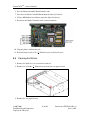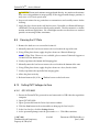
1
SERVICE MANUAL
Innovative Medical Imaging
Fusion DCR TM – Service Manual
Foreword
Proprietary Notice and Disclaimer
The information herein disclosed is the property of iCRco., Inc. Information in this document is subject to change without notice and does not represent a commitment by iCRco to
incorporate changes or improvements in units previously sold or shipped.
No part of this document may be reproduced or transmitted in any form, electronic
or mechanical, including photocopying and recording, for any purpose other than the
purchaser’s own use without the express written permission of iCRco.
Copyright
c iCRco Inc. 2003 - 2011
Copyright All rights reserved.
Trademarks
R iCR 1000,
R iCR 1000 Dual,
R iCR 2600,
R iCR 2600 Dual,
R iCR 2600SF,
R iCR
iCR 2600,
R
R
R
R
R
R
Vet, iCR CR Vet Dual, iCR Mobile, iCR 1-D, iCR Chiro, iCR Chiro Dual, iCR
R iCR 3600SF,
R iCR VERTX,iDR
R
R
,www.icrcompany.com
3600,
and QPC XSCAN32 are
the trademarks of iCRco. All other trademarks are the property of their respective owners,
and are hereby acknowledged.
Terms
Any one of the following iCR products will be referred to as the “CR unit” throughout
R iCR 1000 Dual,
R iCR 2600,
R iCR 2600 Dual,
R iCR 2600SF,
R
this document: iCR 1000,
R iCR Vet,
R iCR Vet Dual,
R iCR Mobile,
R iCR 1-D,
R iCR Chiro,
R iCR Chiro
iCR 3600,
R iCR VERTX
R Any one of the following iCR products will be referred to as “iCR
Dual
R iCR 2600 Dual,
R iCR Vet Dual,
R
dual unit” throughout this document: iCR 1000 Dual,
R Any one of the following iCR products will be referred to as “iCR desktop
iCR Chiro Dual
R The iDRwill
R
unit” throughout this document: iCR VertX.
be referred to as the “DR
unit” throughout this document.
c
2007-2009
Confidential and Proprietary
Property of iCRco, Inc.
i of 40
Document # FDCR-02A Rev A
June 3, 2011
Fusion DCR TM – Service Manual
Contact Information
iCRco., Inc.
Address:
Phone:
Fax:
Email:
Web:
USA
2580 West 237th Street, Torrance, CA, 90505
+1.310.921.9559
+1.310.542.7236
[email protected]
http://www.icrcompany.com
iCRco., Inc.
Address:
Phone:
Email:
Web:
Europe GmbH
Paderborner Str. 21, 44143 Dortmund, Germany
+49.231.92733669
[email protected]
http://www.icrcompany.com
Fusion DCR Information
Please Enter the details of the Fusion DCR system here:
Serial Number:
Date Purchased:
Interface Type:
USB 2.0
c
2007-2009
Confidential and Proprietary
Property of iCRco, Inc.
ii of 40
Document # FDCR-02A Rev A
June 3, 2011
Fusion DCR TM – Service Manual
Safety Information
Read and understand the installation and operating instructions before applying power to
the Fusion DCR.
CAUTION
INPUT: 24VDC
6.3A
CAUTION: FOR CONTINUED
PROTECTION AGAINST RISK OF FIRE,
REPLACE ONLY WITH SAME TYPE AND
RATING OF FUSE.
FUSE
10A, 125V
US and International Patents Granted
EC
US Headquarters
iCRco, Inc.
2580 West 237th Street
Torrance, CA 90505
USA
310-921-9559
FDA 510K Cleared
REP
European Office
iCRco Europe GmbH
Paderborner Str. 21
44143 Dortmund
Germany
+49 231 92733669
0086
CAUTION
CAUTION: TO REDUCE THE RISK OF
ELECTRONIC SHOCK, DO NOT REMOVE
COVER. NO USER SERVICEABLE PARTS
INSIDE. REFER SERVICING TO QUALIFIED
SERVICE PERSONNEL.
DANGER
Invisible laser
radiation when open.
AVOID EXPOSURE
TO BEAM.
Class 3b laser product.
(IEC 825-1)
Conventions
! DANGER A DANGER indicates an imminently hazardous situation which, if not
avoided, will result in death or serious injury. This signal word is to be limited to the most
extreme situations.
! WARNING A WARNING indicates a potentially hazardous situation which, if not
avoided, could result in death or serious injury.
! CAUTION A CAUTION indicates a potentially hazardous situation which, if not
avoided, may result in minor or moderate injury. It may also be used to alert against
unsafe practices.
Note A NOTE indicates important information that helps you make better use of your
Fusion DCR and Software.
Notice A NOTICE indicates either potential damage to hardware or loss of data and tells
you how to avoid the problem.
Laser Safety
!
CAUTION This equipment employs a laser. Laser radiation may be present if the Fusion
DCR is operated without the covers. Avoid the laser beam. Direct exposure to laser light
must be avoided.
The Fusion DCR incorporates a Red ≥ 80mw high-power solid-state laser diode. The Fusion
c
2007-2009
Confidential and Proprietary
Property of iCRco, Inc.
iii of 40
Document # FDCR-02A Rev A
June 3, 2011
Fusion DCR TM – Service Manual
DCR covers protect the service person from direct exposure to laser light. These covers will
protect a user/service person only if they are properly installed. Covers must be removed
and replaced by properly trained service personnel. Contact iCRco if there are any issues
with the covers being damaged or replacement covers are needed.
Electrical Hazards
!
WARNING This equipment is operated with hazardous voltages which can shock, burn,
or cause death.
Notice The Fusion DCR must be connected to a uninterruptible power supply (UPS).
Failure to use a (UPS) will void the warranty.
The equipment must be serviced by properly trained technicians certified by iCRco, Inc.
Do not connect the Fusion DCR with a damaged or sub-standard power cable. Do not
use an extension cord with this device. The Fusion DCR should be properly grounded
and power connections inspected to ensure safe operation. Use at least a 1300VA (780W)
uninterruptible power supply (UPS) with this device, as it is sensitive to variations in
power.
Malfunctioning Equipment
If any iCRco product shows signs of malfunction, discontinue the use of the product
immediately and contact Technical Support at 310-921-9559.
FCC Notification
This equipment generates, uses, and can radiate radio frequency energy, and if not installed
properly, can cause interference with radio communications.
Mammography Use
The Fusion DCR is not intended for Mammography use.
iCRco Warranty
iCRco , Inc. (“iCRco”) values your business and always strives to provide high quality
products and services. All iCRco products are provided with an initial warranty so the
hardware and software are covered from the date of purchase. This limited warranty
solely applies to new products manufactured by or for iCRco and originally purchased
from iCRco or an authorized dealer of iCRco products for your own use. In addition, an
c
2007-2009
Confidential and Proprietary
Property of iCRco, Inc.
iv of 40
Document # FDCR-02A Rev A
June 3, 2011
Fusion DCR TM – Service Manual
extended warranty is available for most new and recently purchased iCRco products for an
additional charge.
Hardware Limited Warranty
iCRco warrants its hardware products to be free of defects in materials and workmanship
for a period of one (1) year from the date of original shipment from iCRco subject to the
limitations set forth herein. If a product proves to be defective in material or workmanship
during the warranty period, iCRco will, at its sole option, repair or replace the product
with a similar product. Repaired and replacement products may be or include refurbished
or remanufactured parts. Any replacement item assumes the remaining warranty period of
the original product. iCRco provides no warranty for any third party hardware or software
included with any product or later acquired.
Software Limited Warranty/Support
iCRco warrants that its QPC XSCAN32, Captera, and/or ClarityPACS software originally
provided with any product will substantially conform to iCRco’s specifications and that
the media, not including hard drives, on which the software is furnished will be free from
defects in materials and workmanship under normal use for a period of one (1) year from
the date of original shipment from iCRco . iCRco’s sole obligation under this warranty is
limited to making reasonable efforts to ensure such conformity and to supply the consumer
with a corrected version of the software as soon as it is practical after the consumer has
notified iCRco of any non conformity. iCRco does not warrant that the operation of any
software will be uninterrupted, glitch or error free or that functions contained in the
software will operate in the combinations which may be selected for use by the user or
meet the user’s requirements. This limited software warranty will be void if the software is
modified without the written approval of iCRco or is used outside of the recommended
parameters or equipment. iCRco does not provide any warranty or support for any other
software.
iCRco agrees to provide one (1) year of telephonic and/or e-mail based support for QPC
XSCAN32, Captera, and/or ClarityPACS software originally provided with any new iCRco
product from the date of original shipment from iCRco . All software support shall be
limited to making reasonable efforts to resolve iCRco software issues and shall be limited
to iCRco’s regular business hours. In addition, iCRco will provide revisions and upgrades
to its software upon request (when available) during the first year after the software was
originally shipped from the iCRco factory. The initial support period will include support
via remote login software, only if the customer has access to the Internet from that PC and
only if the customer agrees iCRco shall have no liability in connection with its support
efforts. Remote login software allows iCRco technical support to remotely access the
customer’s PC via the Internet for the purposes of rendering technical support. Please note
that this warranty, including software support, does not include computer hardware, third
c
2007-2009
Confidential and Proprietary
Property of iCRco, Inc.
v of 40
Document # FDCR-02A Rev A
June 3, 2011
Fusion DCR TM – Service Manual
party software or operating system or network issues, which are outside the control of
iCRco.
Warranty Product Technical Requirements
iCRco requires that all DR, CR, Scanner and/or products requiring PCs be fitted and
installed with a 1300VA (780W) uninterruptible power supply (“UPS”). iCRco recommends
the APC 1000 specification UPS or equivalent. For warranty evaluation and service, iCRco
requires the customer to provide an Internet connection (DSL or Dial-up) or the minimum
of a phone line accessible by an extension cord to the product enabling iCRco technicians to
perform remote diagnostics on installed equipment. In addition, each iCRco product must
be installed, maintained and operated in accordance with the respective product manual.
Failure to comply with these requirements will result in a voided warranty claim.
Requesting Warranty Service
For information on obtaining warranty service, call iCRco’s customer support at (310)9219559. In order to evaluate a warranty service request, iCRco requires the following information: the iCRco serial number of the product, a detailed description of the problem,
customer name and contact information; product location and operating conditions; a copy
of the purchase documents, and sufficient information and authorization, including a liability release as to any loss of data (that should always be backed up), software or network
injury, or downtime, allowing iCRco technicians remote access to the product. Product may
not be returned to iCRco without first obtaining a Return Material Authorization (“RMA”)
number from iCRco . Prior to providing an RMA, iCRco may require remote access to the
product. If iCRco determines that the product may be defective, is under warranty and
necessitates a return to iCRco for service, an RMA number and instructions for return of
the product will be given. iCRco is not responsible for any unauthorized returned product,
i.e. one for which an RMA number has not been issued by iCRco .
Warranty service requires all authorized returns be shipped to the iCRco factory prepaid
and insured. All such authorized returns are the customer’s responsibility. For products
sold and located within the United States, iCRco will pay for return shipping.
Products being returned are only to be shipped in iCRco approved shipping containers.
The original box and packaging materials are approved and should be kept for moving
and/or shipping the product. Approved packaging my also be purchased from iCRco for
an additional charge. iCRco shall have no liability nor responsibility for warranty service
to any product that is not shipped in an iCRco approved shipping container or that is
damaged from incorrect packaging or damaged during shipping.
c
2007-2009
Confidential and Proprietary
Property of iCRco, Inc.
vi of 40
Document # FDCR-02A Rev A
June 3, 2011
Fusion DCR TM – Service Manual
Additional Warranty Limitations and Extent of Warranty
This warranty does not apply if the product has been damaged by accident, misuse or
abuse. In addition, warranty service does not include the repair of failures or defects caused
by: unauthorized attachments to any iCRco product, unsuitable physical or operating
environment, maintenance or repair by anyone other than iCRco or the iCRco authorized
dealer that sold the product, operation of a product beyond its duty cycle, use of the
product outside of its specifications, the use of supplies, parts, materials, software, or
interfaces not furnished, authorized or recommended by iCRco . If the product, including
any software has been opened, tampered with, modified or altered in any way without
written authorization by iCRco , the warranty will no longer apply.
This warranty applies only to products manufactured by, or for, iCRco , and that can be
identified by an “iCRco” serial number as originally affixed to the product. Any modification to the iCRco serial number tag or its attachment to the product shall immediately void
the warranty.
This warranty is non-transferable and subsequent owners must contact iCRco to establish
if the equipment is eligible for an extended warranty.
THERE ARE NO WARRANTIES, EXPRESS OR IMPLIED, WITH RESPECT TO ANY iCRco
PRODUCT OTHER THAN AS SPECIFICALLY SET FORTH HEREIN, AND iCRco SPECIFICALLY DISCLAIMS ANY IMPLIED WARRANTIES OR CONDITIONS OF MERCHANT
ABILITY, FITNESS FOR A PARTICULAR PURPOSE, AND SATISFACTORY QUALITY.
ANY WARRANTIES THAT MAY NOT BE DISCLAIMED UNDER APPLICABLE LAW
ARE LIMITED IN DURATION TO THE INITIAL WARRANTY PERIOD AND NO WARRANTIES, EXPRESS OR IMPLIED, WILL APPLY AFTER THIS PERIOD. ALL INFORMATION, SPECIFICATIONS, PRICES, AND SERVICES ARE SUBJECT TO CHANGE AT ANY
TIME WITHOUT NOTICE.
Limitation of Remedies and Liability/Exclusion of Damages
The exclusive remedy for any defective product is limited to the repair or replacement of
the defective product. iCRco shall have a reasonable time after determining that a defective
product exists to repair or replace a defective product. iCRco’s entire liability for any
product is limited to the actual purchase price for the product. This limitation applies even
if iCRco cannot or does not repair or replace any defective product.
IN NO EVENT WILL iCRco BE LIABLE FOR ANY GENERAL, SPECIAL, CONSEQUENTIAL OR INCIDENTAL DAMAGES, including but not limited to, damages related to
the loss of use, loss of recorded product, the installation of replacement product, or any
inspection, testing, or redesign caused by any defect or by the repair or replacement of any
product arising from a defect in any product. This exclusion of damages applies even if
the customer advises iCRco or an iCRco dealer of the possibility of such damages. This
limitation of remedies also applies to claims against any suppliers or dealers of iCRco . iCRco and its
suppliers’ and dealers’ limitations of remedies are not cumulative. Such suppliers and dealers are
c
2007-2009
Confidential and Proprietary
Property of iCRco, Inc.
vii of 40
Document # FDCR-02A Rev A
June 3, 2011
Fusion DCR TM – Service Manual
intended beneficiaries of this limitation. iCRco is not liable for any claim by or against the customer
arising from a third party claim.
Revision History
Revision
A
Author
MS
Date
2011-06-03
c
2007-2009
Confidential and Proprietary
Property of iCRco, Inc.
Notes
Initial Release
viii of 40
Document # FDCR-02A Rev A
June 3, 2011
Fusion DCR TM – Service Manual
Contents
Foreword
Contact Information . . . . . . . . . . . . . . . . . . . . . . . . . . . . . . . . . . .
Safety Information . . . . . . . . . . . . . . . . . . . . . . . . . . . . . . . . . . . .
iCRco Warranty . . . . . . . . . . . . . . . . . . . . . . . . . . . . . . . . . . . . . .
i
ii
iii
iv
1
Introduction
1.1 Overview . . . . . . . . . . . . . . . . . . . . . . . . . . . . . . . . . . . . . . .
1
1
2
Pre-Installation
2.1 Voltage Requirements . . . . . .
2.2 Environmental . . . . . . . . . . .
2.3 Connectivity and Power Supply .
2.4 Power Switch . . . . . . . . . . .
2.5 Power and Scan Lights . . . . . .
2.6 Physical Requirements . . . . . .
2.7 System Specifications . . . . . . .
2.7.1 Power Requirements . . .
2.7.2 Cassette Sizes . . . . . . .
2.7.3 Pixels Per Line Resolution
2.7.4 Scan Rate . . . . . . . . .
2.7.5 Grey Scale Resolution . .
2.7.6 Interface . . . . . . . . . .
2.7.7 Dimensions . . . . . . . .
2.7.8 Temperature Conditions .
2.7.9 Humidity . . . . . . . . .
2.7.10 Vibration/Acceleration .
2.7.11 Altitude . . . . . . . . . .
2.7.12 Weight . . . . . . . . . . .
.
.
.
.
.
.
.
.
.
.
.
.
.
.
.
.
.
.
.
2
2
2
2
2
3
3
3
3
3
3
3
4
4
4
4
4
4
4
4
.
.
.
.
5
5
5
6
6
4
Software Installation
4.1 PC Specifications . . . . . . . . . . . . . . . . . . . . . . . . . . . . . . . . . .
4.2 Installing USB Drivers . . . . . . . . . . . . . . . . . . . . . . . . . . . . . . .
4.3 Installing Captera . . . . . . . . . . . . . . . . . . . . . . . . . . . . . . . . . .
7
7
7
7
5
System Operation
3
Hardware Installation
3.1 Unpacking Instructions . . . . . .
3.2 Installing the Power Cable . . . .
3.2.1 International Power Cable
3.3 Installing the USB Cable . . . . .
c
2007-2009
Confidential and Proprietary
Property of iCRco, Inc.
.
.
.
.
.
.
.
.
.
.
.
.
.
.
.
.
.
.
.
.
.
.
.
.
.
.
.
.
.
.
.
.
.
.
.
.
.
.
.
.
.
.
.
.
.
.
.
.
.
.
.
.
.
.
.
.
.
.
.
.
.
.
.
.
.
.
.
.
.
.
.
.
.
.
.
.
.
.
.
.
.
.
.
.
.
.
.
.
.
.
.
.
.
.
.
.
.
.
.
.
.
.
.
.
.
.
.
.
.
.
.
.
.
.
.
.
.
.
.
.
.
.
.
.
.
.
.
.
.
.
.
.
.
.
.
.
.
.
.
.
.
.
.
.
.
.
.
.
.
.
.
.
.
.
.
.
.
.
.
.
.
.
.
.
.
.
.
.
.
.
.
.
.
.
.
.
.
.
.
.
.
.
.
.
.
.
.
.
.
.
.
.
.
.
.
.
.
.
.
.
.
.
.
.
.
.
.
.
.
.
.
.
.
.
.
.
.
.
.
.
.
.
.
.
.
.
.
.
.
.
.
.
.
.
.
.
.
.
.
.
.
.
.
.
.
.
.
.
.
.
.
.
.
.
.
.
.
.
.
.
.
.
.
.
.
.
.
.
.
.
.
.
.
.
.
.
.
.
.
.
.
.
.
.
.
.
.
.
.
.
.
.
.
.
.
.
.
.
.
.
.
.
.
.
.
.
.
.
.
.
.
.
.
.
.
.
.
.
.
.
.
.
.
.
.
.
.
.
.
.
.
.
.
.
.
.
.
.
.
.
.
.
.
.
.
.
.
.
.
.
.
.
.
.
.
.
.
.
.
.
.
.
.
.
.
.
.
.
.
.
.
.
.
.
.
.
.
.
.
.
.
.
.
.
.
.
.
.
.
.
.
.
.
.
.
.
.
.
.
.
.
.
.
.
.
.
.
.
.
.
.
.
.
.
.
.
.
.
.
.
.
.
.
.
.
.
.
.
.
.
.
.
.
.
.
.
.
.
.
.
.
.
.
.
.
.
.
.
.
.
.
.
.
.
.
.
.
.
.
.
.
.
.
.
.
.
.
.
.
.
.
.
.
.
.
.
.
.
.
.
.
.
.
.
.
.
.
.
.
.
.
.
.
.
.
.
.
.
.
.
.
.
.
.
.
.
.
.
.
.
.
.
.
.
.
.
.
.
.
.
.
.
.
.
.
.
.
.
.
.
.
.
.
.
.
.
.
.
.
.
.
.
.
.
.
.
.
.
.
.
.
.
11
ix of 40
Document # FDCR-02A Rev A
June 3, 2011
Fusion DCR TM – Service Manual
5.1
5.2
5.3
5.4
5.5
6
7
Power-Up . . . . . . . . . . . . . . . . . . . . . .
Cassette Handling . . . . . . . . . . . . . . . . . .
5.2.1 Overview . . . . . . . . . . . . . . . . . .
5.2.2 Weight/Force Applied to Cassette . . . .
5.2.3 Cassette Storage . . . . . . . . . . . . . . .
5.2.4 Cassette Contamination . . . . . . . . . .
Cassette Loading . . . . . . . . . . . . . . . . . .
5.3.1 CR Mode . . . . . . . . . . . . . . . . . . .
5.3.2 DR Mode . . . . . . . . . . . . . . . . . .
Schedule of Maintenance . . . . . . . . . . . . . .
Periodic Cleaning . . . . . . . . . . . . . . . . . .
5.5.1 Cleaning the Outside of the Fusion DCR
5.5.2 Cassette Cleaning . . . . . . . . . . . . . .
Theory of Operation
6.1 Product Overview . . . . . . . . . . .
6.2 System Configuration . . . . . . . . .
6.2.1 Optical Beam Path . . . . . .
6.2.2 Digital and Electrical Systems
6.2.3 Galvonometer Board . . . . .
6.2.4 Indicator Board . . . . . . . .
6.2.5 Anti-Jitter Board . . . . . . .
6.2.6 PMT Board . . . . . . . . . .
6.2.7 Power Distribution Board . .
6.2.8 LED Eraser Board . . . . . . .
6.2.9 Motor Controller Board . . .
6.2.10 Analog to Digital Conversion
6.2.11 Calibration . . . . . . . . . . .
6.2.12 PMT Amplifier . . . . . . . .
.
.
.
.
.
.
.
.
.
.
.
.
.
.
.
.
.
.
.
.
.
.
.
.
.
.
.
.
.
.
.
.
.
.
.
.
.
.
.
.
.
.
.
.
.
.
.
.
.
.
.
.
.
.
.
.
.
.
.
.
.
.
.
.
.
.
.
.
.
.
.
.
.
.
.
.
.
.
.
.
.
.
.
.
.
.
.
.
.
.
.
.
.
.
.
.
.
.
Diagnostics
7.1 Overview . . . . . . . . . . . . . . . . . . . . . . .
7.2 Using the Focus Tool for Hardware Diagnostics .
7.3 Image Symptoms . . . . . . . . . . . . . . . . . .
7.3.1 Lint in the Scan Path . . . . . . . . . . . .
7.3.2 Dust Lines . . . . . . . . . . . . . . . . . .
7.3.3 Horizontal Lines in Image . . . . . . . . .
7.3.4 Banding Top/Bottom 17” Length . . . . .
7.3.5 Up-side Down Cassette . . . . . . . . . .
7.3.6 Grid Lines/Moiré Effect . . . . . . . . . .
7.3.7 Eraser Offset . . . . . . . . . . . . . . . . .
7.3.8 Image Jitter . . . . . . . . . . . . . . . . .
7.3.9 Over Exposure . . . . . . . . . . . . . . .
7.3.10 Random Imaging Shifting . . . . . . . . .
7.4 Hardware Symptoms . . . . . . . . . . . . . . . .
c
2007-2009
Confidential and Proprietary
Property of iCRco, Inc.
x of 40
.
.
.
.
.
.
.
.
.
.
.
.
.
.
.
.
.
.
.
.
.
.
.
.
.
.
.
.
.
.
.
.
.
.
.
.
.
.
.
.
.
.
.
.
.
.
.
.
.
.
.
.
.
.
.
.
.
.
.
.
.
.
.
.
.
.
.
.
.
.
.
.
.
.
.
.
.
.
.
.
.
.
.
.
.
.
.
.
.
.
.
.
.
.
.
.
.
.
.
.
.
.
.
.
.
.
.
.
.
.
.
.
.
.
.
.
.
.
.
.
.
.
.
.
.
.
.
.
.
.
.
.
.
.
.
.
.
.
.
.
.
.
.
.
.
.
.
.
.
.
.
.
.
.
.
.
.
.
.
.
.
.
.
.
.
.
.
.
.
.
.
.
.
.
.
.
.
.
.
.
.
.
.
.
.
.
.
.
.
.
.
.
.
.
.
.
.
.
.
.
.
.
.
.
.
.
.
.
11
11
11
11
11
12
12
12
12
12
13
13
13
.
.
.
.
.
.
.
.
.
.
.
.
.
.
.
.
.
.
.
.
.
.
.
.
.
.
.
.
.
.
.
.
.
.
.
.
.
.
.
.
.
.
.
.
.
.
.
.
.
.
.
.
.
.
.
.
.
.
.
.
.
.
.
.
.
.
.
.
.
.
.
.
.
.
.
.
.
.
.
.
.
.
.
.
.
.
.
.
.
.
.
.
.
.
.
.
.
.
.
.
.
.
.
.
.
.
.
.
.
.
.
.
.
.
.
.
.
.
.
.
.
.
.
.
.
.
.
.
.
.
.
.
.
.
.
.
.
.
.
.
.
.
.
.
.
.
.
.
.
.
.
.
.
.
.
.
.
.
.
.
.
.
.
.
.
.
.
.
.
.
.
.
.
.
.
.
.
.
.
.
.
.
.
.
.
.
.
.
.
.
.
.
.
.
.
.
.
.
.
.
.
.
.
.
.
.
.
.
.
.
.
.
.
.
.
.
.
.
.
.
.
.
.
.
15
15
15
15
16
16
16
16
17
17
17
17
18
18
18
.
.
.
.
.
.
.
.
.
.
.
.
.
.
19
19
20
22
22
23
23
24
25
25
26
27
27
28
28
.
.
.
.
.
.
.
.
.
.
.
.
.
.
.
.
.
.
.
.
.
.
.
.
.
.
.
.
.
.
.
.
.
.
.
.
.
.
.
.
.
.
.
.
.
.
.
.
.
.
.
.
.
.
.
.
.
.
.
.
.
.
.
.
.
.
.
.
.
.
.
.
.
.
.
.
.
.
.
.
.
.
.
.
.
.
.
.
.
.
.
.
.
.
.
.
.
.
.
.
.
.
.
.
.
.
.
.
.
.
.
.
.
.
.
.
.
.
.
.
.
.
.
.
.
.
.
.
.
.
.
.
.
.
.
.
.
.
.
.
.
.
.
.
.
.
.
.
.
.
.
.
.
.
.
.
.
.
.
.
.
.
.
.
.
.
.
.
.
.
.
.
.
.
.
.
.
.
.
.
.
.
.
.
.
.
.
.
.
.
.
.
.
.
.
.
.
.
.
.
.
.
.
.
.
.
.
.
.
.
Document # FDCR-02A Rev A
June 3, 2011
Fusion DCR TM – Service Manual
7.5
8
7.4.1 Failure to Initialize USB . . . . . .
7.4.2 No Motor Movement . . . . . . . .
7.4.3 Clicking Noise Returning to Home
7.4.4 Not Finding Home Position . . . .
7.4.5 Motor Gear/Slide Lines . . . . . .
7.4.6 Cassette Door Stays Open . . . . .
7.4.7 Cassette Stuck in CR unit . . . . .
Error Message: No Data Acquired . . . .
7.5.1 Failure Analysis 1 . . . . . . . . . .
7.5.2 Failure Analysis 2 . . . . . . . . . .
Service and Maintenance Procedures
8.1 Removing the Front Cover . . . . . . . .
8.2 Removing the Back Cover . . . . . . . .
8.3 Accessing the Scan Slot . . . . . . . . . .
8.4 Changing the Brushes . . . . . . . . . .
8.4.1 Caterpillar Brush . . . . . . . . .
8.5 Replacing the Power Distribution Board
8.6 Checking the Fuses . . . . . . . . . . . .
8.6.1 External Fuses . . . . . . . . . . .
8.6.2 Power Distribution Board Fuses
8.7 Replacing the Motor Controller Board .
8.8 Cleaning the Mirrors . . . . . . . . . . .
8.9 Cleaning the IP Plate . . . . . . . . . . .
8.10 Setting PMT Voltages to Zero . . . . . .
8.10.1 QPC XSCAN32 . . . . . . . . . .
8.10.2 Captera . . . . . . . . . . . . . .
c
2007-2009
Confidential and Proprietary
Property of iCRco, Inc.
xi of 40
.
.
.
.
.
.
.
.
.
.
.
.
.
.
.
.
.
.
.
.
.
.
.
.
.
.
.
.
.
.
.
.
.
.
.
.
.
.
.
.
.
.
.
.
.
.
.
.
.
.
.
.
.
.
.
.
.
.
.
.
.
.
.
.
.
.
.
.
.
.
.
.
.
.
.
.
.
.
.
.
.
.
.
.
.
.
.
.
.
.
.
.
.
.
.
.
.
.
.
.
.
.
.
.
.
.
.
.
.
.
.
.
.
.
.
.
.
.
.
.
.
.
.
.
.
.
.
.
.
.
.
.
.
.
.
.
.
.
.
.
.
.
.
.
.
.
.
.
.
.
.
.
.
.
.
.
.
.
.
.
.
.
.
.
.
.
.
.
.
.
.
.
.
.
.
.
.
.
.
.
.
.
.
.
.
.
.
.
.
.
.
.
.
.
.
.
.
.
.
.
.
.
.
.
.
.
.
.
.
.
.
.
.
.
.
28
29
29
30
30
30
30
31
31
32
.
.
.
.
.
.
.
.
.
.
.
.
.
.
.
.
.
.
.
.
.
.
.
.
.
.
.
.
.
.
.
.
.
.
.
.
.
.
.
.
.
.
.
.
.
.
.
.
.
.
.
.
.
.
.
.
.
.
.
.
.
.
.
.
.
.
.
.
.
.
.
.
.
.
.
.
.
.
.
.
.
.
.
.
.
.
.
.
.
.
.
.
.
.
.
.
.
.
.
.
.
.
.
.
.
.
.
.
.
.
.
.
.
.
.
.
.
.
.
.
.
.
.
.
.
.
.
.
.
.
.
.
.
.
.
.
.
.
.
.
.
.
.
.
.
.
.
.
.
.
.
.
.
.
.
.
.
.
.
.
.
.
.
.
.
.
.
.
.
.
.
.
.
.
.
.
.
.
.
.
.
.
.
.
.
.
.
.
.
.
.
.
.
.
.
.
.
.
.
.
.
.
.
.
.
.
.
.
.
.
.
.
.
.
.
.
.
.
.
.
.
.
.
.
.
.
.
.
.
.
.
.
.
.
.
.
.
.
.
.
.
.
.
.
.
.
.
.
.
.
.
.
.
.
.
.
.
.
.
.
.
.
.
.
.
.
.
.
.
.
.
.
.
.
.
.
.
.
.
.
.
.
.
.
.
.
.
.
.
.
.
.
.
.
.
.
.
.
.
.
35
35
35
35
36
36
36
37
37
37
37
38
39
39
39
40
Document # FDCR-02A Rev A
June 3, 2011
Fusion DCR TM – Service Manual
1. Introduction
1.1
Overview
The Fusion DCR is an ultra high resolution Computed Radiography device. It is designed
to scan cassettes containing phosphor screens (CR plates) or the embedded phosphor screen
using patented technology. CR plates are transported past a scanning head without bending
or using rollers. This flat scan path results in ultra high resolution images with high fidelity
across the entire image. High resolution is achieved from the CR plates by coupling the flat
scan path with a high energy laser.
The Fusion DCR collects 16 Bit data that is converted to a DICOM 3.0 image and can be
stored, viewed, manipulated, and sent to any other storage device, printer, or viewing
station through DICOM. This document contains a basic technical overview of the CR unit
including the optical systems, electronic components, and driving software subsystems.
A general description of the systems functionality and user interfaces will be described.
Unpacking of the hardware is covered, as is software installation, and troubleshooting
are also included. This document is intended for users who need to understand the basic
underlying principles of operation for the CR unit.
c
2007-2009
Confidential and Proprietary
Property of iCRco, Inc.
1 of 40
Document # FDCR-02A Rev A
June 3, 2011
Fusion DCR TM – Service Manual
2. Pre-Installation
2.1
Voltage Requirements
iCRco employs CE certified medical grade power supplies. The Fusion DCR is supplied
with a DC power supply that allows the unit to work between 18 to 36 VDC, 6.3 amps and
150 watts. iCRco provides a medical power converter.
Do not substitute or switch the power converter. Substituting or switching the power
converter will void the warranty. Contact iCRco Tech Support to obtain a replacement
power converter.
2.2
Environmental
The Fusion DCR should not be placed in a room with a film processor present. This will
void the warranty. The humidity and temperature limits are 20 to 95% non-condensing,
and 59◦ F to 95◦ F (15◦ C to 35◦ C), operating, respectively.
Installation of the Fusion DCR near high magnetic fields may cause the Fusion DCR to
malfunction. The Fusion DCR should not be placed in a room with an MRI, CT, X-ray
sources or any other equipment that produces high magnetic fields.
The room should have good ventilation. Another factor to consider prior to installing the
Fusion DCR is dust and particulates in the environment. The Fusion DCR is designed to be
resistant to dust and particulates that may be present at the installation site.
2.3
Connectivity and Power Supply
The room needs to have wall power and the Fusion DCR should not be used with an
extension cord. Use at least a 1300VA (780W) uninterruptible power supply (UPS) between
the wall power and the Fusion DCR. A network connection is required for technical support.
Alternatively, the user must have a phone/fax line that can be connected to the PC as a
minimum to comply with iCRco warranty terms.
2.4
Power Switch
The power switch is located on the top, left-hand side of the Fusion DCR.
c
2007-2009
Confidential and Proprietary
Property of iCRco, Inc.
2 of 40
Document # FDCR-02A Rev A
June 3, 2011
Fusion DCR TM – Service Manual
2.5
Power and Scan Lights
The Power and Scan lights are located on the lower, right-hand side of the Fusion DCR.
When the Fusion DCR is powered on, the green light is illuminated. While the unit is
scanning the yellow light will blink.
2.6
Physical Requirements
The Fusion DCR requires a stable operating environment. It is important the Fusion DCR is
placed in the provided wall or cart mount.
2.7
2.7.1
System Specifications
Volts:
Amps:
Max Power:
2.7.2
2.7.3
Power Requirements
18-36 VDC
6.3 A
150 Watts
3556 (High Resolution) over 14 inches (356 mm)
2268 (Normal Resolution) over 14 inches (356 mm)
Cassette Sizes
2.7.4
14x17’ and 10x12” (CR Mode)
14x17” active capture area (DR Mode)
c
2007-2009
Confidential and Proprietary
Property of iCRco, Inc.
Pixels Per Line Resolution
Scan Rate
50-148 lines/second
3 of 40
Document # FDCR-02A Rev A
June 3, 2011
Fusion DCR TM – Service Manual
2.7.5
Grey Scale Resolution
2.7.9
Humidity
16 bits (65,535 dhades of gray)
20 to 80% non-condensing
2.7.6
2.7.10
Interface
USB 2.0
2.7.7
3-4G Max (in shipping)
Dimensions
2.7.11
39H x 22W x 7.5H inches
2.7.8
Vibration/Acceleration
0 to 9,500 ft. - operating
Temperature Conditions
95◦ F
15 to
-1 to 150◦ F
Altitude
2.7.12
Weight
35◦ C)
(10 to
- operating
(-1 to 65◦ C) - non-operating
c
2007-2009
Confidential and Proprietary
Property of iCRco, Inc.
4 of 40
82 pounds
Document # FDCR-02A Rev A
June 3, 2011
Fusion DCR TM – Service Manual
3. Hardware Installation
3.1
Unpacking Instructions
1. Open the box from the top.
2. Remove any small accessories loaded into the top of the box.
3. With at least two (2) people, lift the Fusion DCR out of the box.
! CAUTION Always practice proper heavy lifting procedures. Failure to practice
proper lifting procedures may result in injury or damage to the unit.
4. Store the box and any foam inserts somewhere safe & dry, so that if the Fusion DCR
needs to be shipped again, there are packing materials available.
3.2
Installing the Power Cable
1. Plug the power cable for the Fusion DCR into the power switch unit.
2. Plug the other end of the power switch cord into the UPS.
3. Make sure the UPS is not in bypass mode.
c
2007-2009
Confidential and Proprietary
Property of iCRco, Inc.
5 of 40
Document # FDCR-02A Rev A
June 3, 2011
Fusion DCR TM – Service Manual
4. Plug the UPS into a standard wall outlet.
3.2.1
International Power Cable
The Fusion DCR utilizes an international IEC grade connector for the power cable. Systems
are shipped with a standard NEMA 5-15 hospital grade cable. The cable needs to be
changed depending on the male end, which varies from country to country.
3.3
Installing the USB Cable
The USB cable for the Fusion DCR is installed at the factory.
1. Visually inspect the cable to ensure that it is not cut, frayed, or otherwise damage.
2. Plug the USB A end of the cable end into a free USB 2.0 port on the computer.
c
2007-2009
Confidential and Proprietary
Property of iCRco, Inc.
6 of 40
Document # FDCR-02A Rev A
June 3, 2011
Fusion DCR TM – Service Manual
4. Software Installation
4.1
PC Specifications
The minimum requirements for the Acquisition computer are as follows:
Processor:
Intel Core2Duo or greater (No support for AMD processors)
RAM:
2 GB (4GB reccomended)
OS:
Windows XP or Windows 7 32-bit Operating System only
HDD:
250 GB or more
Video Card: 512 MB* or greater
*512 MB of RAM on the video card is recommended for non-diagnostic stations only.
Consult the monitor manufacturer for video card recommendations for medical monitors.
4.2
Installing USB Drivers
USB drivers for iCRco hardware are installed automatically with the installation of Captera.
4.3
Installing Captera
1. Insert the media containing the Captera installing in the computer.
2. Double click Setup.exe to begin the installation process.
3. Click Next at the Welcome screen.
4. Check the box next to I accept the terms in the Licence Agreement, then click Next to
continue.
c
2007-2009
Confidential and Proprietary
Property of iCRco, Inc.
7 of 40
Document # FDCR-02A Rev A
June 3, 2011
Fusion DCR TM – Service Manual
5. Click Next at the Custom Setup screen to continue.
6. Click Install to begin the installation.
7. Please be patient while Captera installs. Depending on the speed of the computer
and available RAM, this process could take a few minutes.
c
2007-2009
Confidential and Proprietary
Property of iCRco, Inc.
8 of 40
Document # FDCR-02A Rev A
June 3, 2011
Fusion DCR TM – Service Manual
8. Click Continue Anyway if prompted by the Windows compatibility wizard.
9. Click Ok at the Captera device attachement dialog.
10. Click Finish to finish the Captera installation.
c
2007-2009
Confidential and Proprietary
Property of iCRco, Inc.
9 of 40
Document # FDCR-02A Rev A
June 3, 2011
Fusion DCR TM – Service Manual
c
2007-2009
Confidential and Proprietary
Property of iCRco, Inc.
10 of 40
Document # FDCR-02A Rev A
June 3, 2011
Fusion DCR TM – Service Manual
5. System Operation
5.1
Power-Up
1. Make sure the power cord is properly installed in the power module.
2. Make sure the power cord is properly installed in the UPS and the UPS is plugged
into a standard wall outlet.
3. Make sure the USB 2.0 cord is properly installed in the Fusion DCR and computer.
4. Power on the computer.
5. Power on the Fusion DCR by pressing the power switch.
5.2
5.2.1
Cassette Handling
Overview
Unlike other solutions, the Fusion DCR does not allow for contact to the delicate phosphor
imaging plate. The hard X-ray cassette is designed to protect the plate and allow for it to be
read by the Fusion DCR. The delicate imaging plate is embedded within a rigid cassette in
such a way that nothing touches the plate during the scanning or handling process.
5.2.2
Weight/Force Applied to Cassette
Apply only minimal weight and/or force to the cassette (for example, do not have a patient
stand on the cassette for weight-bearing views). Use a weight-bearing cap when necessary.
!
WARNING Excessive weight/force may damage the cassette and may cause the CR
unit to malfunction. Do not apply excessive weight/force to the cassette.
5.2.3
Cassette Storage
All cassettes should be stored in the cleanest, driest conditions possible. Always store
cassettes in a location where they are not likely to be knocked over or damaged. With
careful handling the cassette plate system should provide years of service as there is no
known lifetime for the phosphors used in the plate system.
c
2007-2009
Confidential and Proprietary
Property of iCRco, Inc.
11 of 40
Document # FDCR-02A Rev A
June 3, 2011
Fusion DCR TM – Service Manual
5.2.4
Cassette Contamination
Should the situation arise where a cassette may come in contact with bodily fluids or other
contaminated materials, place the cassette in a clean plastic bag before exposing the X-ray.
This will ensure that the cassette stays clean and usable.
5.3
Cassette Loading
The method of cassette loading depends on the mode in which the device is being operated.
5.3.1
CR Mode
1. Choose the cassette size (10x12” or 14x17”) by moving the metal rod on the right side
of the scan slot to the appropriate position.
2. Load the cassette into the Fusion DCR. The black, carbon side of the cassette faces
towards the back of the Fusion DCR unit.
!
CAUTION Do not use excessive force when loading the cassette! The cassette will
not fit if the orientation is incorrect.
5.3.2
DR Mode
The imaging plate is already present in DR mode. The front of the device holds imaging
plate, and is exposed to X-rays.
5.4
Schedule of Maintenance
The following is a schedule of maintenance for the Fusion DCR.
The following maintenance may be performed by end users:
Maintenance Procedure
Deep Erase Cassettes
Clean cassettes
Clean Fusion DCR exterior covers
Frequency
Daily
Weekly
Monthly
The following Fusion DCR maintenance must be performed by an iCRco authorized service
engineer only:
c
2007-2009
Confidential and Proprietary
Property of iCRco, Inc.
12 of 40
Document # FDCR-02A Rev A
June 3, 2011
Fusion DCR TM – Service Manual
Maintenance Procedure
Clean mirrors
Vacuum inside case
Clean fan filters
Frequency
Yearly
Yearly
Monthly or when visibly dirty.
The following Fusion DCR calibration maintenance must be performed by an iCRco authorized service engineer only:
Maintenance Procedure
Check image performance (Contrast/Noise Ratio and Spacial Resolution)
Perform Exposure Index calibration
5.5
Frequency
Quarterly
Yearly
Periodic Cleaning
Periodic cleaning of iCRco products should be done on a monthly basis.
5.5.1
Cleaning the Outside of the Fusion DCR
Note It is important that the covers remain on the Fusion DCR at all times. The covers
should only be removed for service by an iCRco authorized technician, then immediately
replaced.
! CAUTION Do not clean the galvo mirror. Dust and fibers in the laser beam path may
affect the radiographic image.
The outside covers of the Fusion DCR should be cleaned with a slightly dampened cloth or
R
R
c
a dry cloth moistened with BallSUNUP
glass
cleaner or Spraywayglass
cleaner.
5.5.2
Cassette Cleaning
Notice At no time should abrasive cleaners or chemicals be used to clean the cassette or
plate.
Cleaning the Outside of the Cassette
1. Moisten a clean, lint-free cloth with a mild soap or detergent using soft water.
2. Wipe down the cassette covers thoroughly.
3. Allow the cassette to air dry.
c
2007-2009
Confidential and Proprietary
Property of iCRco, Inc.
13 of 40
Document # FDCR-02A Rev A
June 3, 2011
Fusion DCR TM – Service Manual
Cleaning the IP Plate
1. With a finger, press the cassette catch located on the side rail on the cassette. This will
release the carbon fiber door from the cassette.
2. Examine the imaging plate for dust or particulates.
3. Using iCRco plate cleaner, apply the plate cleaner to a clean, lint-free cloth.
Note If iCRco Plate Cleaner is not available, please contact Technical Support at
1-310-921-9559 to obtain more.
4. Gently wipe down the imaging plate with the clean, lint-free cloth.
5. Allow the plate to air dry before sliding the carbon fiber door back into place.
c
2007-2009
Confidential and Proprietary
Property of iCRco, Inc.
14 of 40
Document # FDCR-02A Rev A
June 3, 2011
Fusion DCR TM – Service Manual
6. Theory of Operation
6.1
Product Overview
The Fusion DCR produces a diagnostic quality, 16 bit image from a medical grade storagephosphor image plate. The optical assembly provides a flying spot laser with a focal spot
size of 80 microns. The laser scans across the plate and data is captured at a given rate.
Each sample is reassembled to create an image. The capture sampling rate can be modified
to create images with resolutions from 100 microns (250 DPI) to 200 microns (120 DPI). The
unit can scan images up to 35 cm x 48 cm. The laser spot focused to 80 microns is moved
back and forth across an imaging plate as the plate is moved through the Fusion DCR. The
resultant Digital X-ray can be viewed, manipulated and stored and even printed to a film
or paper image. The images are stored and manipulated using the standard medical image
format (DCM) and the medical imaging transfer protocol, DICOM 3.0.
6.2
6.2.1
System Configuration
Optical Beam Path
The Fusion DCR contains a 664 nm 15 mW laser, Lens optic and four mirrors, a scanning
galvanometer, and a light collection system.
The round laser spot is focused through a focusing lens to produce a round output beam.
The beam is deflected by a galvanometer scanner to produce the scan across the plate. The
folding mirrors bend the beam and the focused laser spot travels vertically down the plate
as it moves horizontally across the scan head.
In order to reach the plate, the beam passes through an integrating collection cylinder. As it
hits the surface of the plate, the red light from the focused laser stimulates blue emission
from the image plate in direct proportion to the X-ray energy stored in the image plate as a
result of the exposure. This blue light is collected by the integrating cylinder. The red light
is blocked from reaching the sensors by blue glass filters.
The collected blue light is detected by photomultiplier sensors, which convert the photons
into a signal.
This signal is then logarithmically amplified, corrected for spatial variations in the system sensitivity across the width of the screen, and then digitized by an A/D converter.
c
2007-2009
Confidential and Proprietary
Property of iCRco, Inc.
15 of 40
Document # FDCR-02A Rev A
June 3, 2011
Fusion DCR TM – Service Manual
Optical Cavity Overview
6.2.2
Digital and Electrical Systems
6.2.3
Galvonometer Board
The Galvo Servo board contains a feedback amplifier that results in extremely accurate
control of the mirror mounted on the shaft of the scanning galvanometer.
The galvo motor shaft oscillates back and forth through an arc of approximately 30 degrees
at a rate of 148Hz. A small mirror attached to the shaft intercepts the static laser beam and
sweeps (scans) it across the width of the image plate.
6.2.4
Indicator Board
Two LED indicator lamps are used to signal scanner power ON and SCAN status. The
SCAN indicator is turned on only while a scan is in process; it also blinks whenever the
plate is in the optical path.
6.2.5
Anti-Jitter Board
A small L shaped board located at the end of the integration cylinder.
c
2007-2009
Confidential and Proprietary
Property of iCRco, Inc.
16 of 40
Document # FDCR-02A Rev A
June 3, 2011
Fusion DCR TM – Service Manual
6.2.6
PMT Board
The photomultiplier tube amplifies the photons from the plate and converts them into
electrical signals.
6.2.7
Power Distribution Board
The Fusion DCR Uses Four Power Supplies:
Large supply: ±18V, ±12V , +5 V.
Small supply: +24 V.
High Voltage Supply (PMTs): 1000 V.
! WARNING Do not handle the power supply when the Fusion DCR is on. Do not
disconnect cables when unit is powered up.
6.2.8
LED Eraser Board
The LED Eraser board provides single wavelength light to erase plate.
6.2.9
Motor Controller Board
This section of the Fusion DCR controls the stepping motor to drive the plate past the scan
head and return it to the home position.
Block Diagram
c
2007-2009
Confidential and Proprietary
Property of iCRco, Inc.
17 of 40
Document # FDCR-02A Rev A
June 3, 2011
Fusion DCR TM – Service Manual
6.2.10
Analog to Digital Conversion
During the scanning process signals are generated by the PMT sensors and transmitted to
the computer through a USB 2.0 interface cable. A trigger signal generated by the laser spot
is transmitted to the PMT board to trigger a line capture. Image is assembled from lines of
captured data that is held in registers and translated into a 16 bit raw source file. There is
no way to pause the data capture process. Cancel will cause the machine to stop and return
to home position. Data on the plate will be lost.
Note If an image is cancelled during the scan process, the plate will have to be erased
again to ensure that the plate is entirely erased.
6.2.11
Calibration
Gain Adjustment
Gain Control is used to compensate for reduction in sensitivity of the PMT detectors due to
age. The gain can be adjusted in the software.
1. Open QPC Xscan32
2. Create/open patient
3. Click on Scan (if it is a patient with no images the scan dialog will automatically
appear).
4. The Quality Processing Center dialog will appear.
5. Click on the Settings button and type in the password ‘earl’. It is case sensitive.
6. A dialog box will appear where the user can manually change the gain.
6.2.12
PMT Amplifier
The amplifier is the interface between the PMT receiving the stimulated light from the
collection chamber. The amplifier serves as a current to voltage converter and a log
amplifier.
c
2007-2009
Confidential and Proprietary
Property of iCRco, Inc.
18 of 40
Document # FDCR-02A Rev A
June 3, 2011
Fusion DCR TM – Service Manual
7. Diagnostics
7.1
Overview
Our Technical Support team is here to help, Monday though Friday (excluding holidays),
from 7:00 AM to 7:00 PM, Pacific Standard Time at (310) 921-9559, or via e-mail at [email protected]. Online support documentation and videos are available at
http://www.icrcompany.com. Please do not hesitate to contact us for assistance.
If a system failure occurs, it is necessary to diagnose the cause before beginning the repair.
This section describes the diagnostic tools and techniques used to isolate various types of
system failures. This chapter covers the most common failures and their fixes. If the user is
unsure how to proceed with troubleshooting, please contact Technical Support.
The cause of some failures may be obvious. In these cases, the Service Engineer may proceed
directly to the repair. Before beginning an investigation, it is a good practice to record
as much information about the current state of the system as possible. This information
may include, but is not limited to, symptoms, conditions under which symptoms exist,
voltages, settings, cleanliness, and visual state. Normal generic troubleshooting techniques
apply. With knowledge of the system, isolate the failure to a particular subsystem. With
knowledge of the subsystem, trace the symptom back to its cause. In many cases, failures
are caused by lack of periodic maintenance and cleaning. If a system is known to be behind
schedule for its maintenance and cleaning at the time of the failure, it is a good practice
to clean and re-calibrate the system before extensive troubleshooting. In many cases this
solves the problem or provides clues as to the cause.
!
WARNING This equipment is operated with hazardous voltages which can shock, burn,
or cause death.
!
CAUTION This equipment uses a laser. Direct exposure to the laser beam must be
avoided.
!
CAUTION Do not operate the unit with the covers removed. Operating the Fusion DCR
with the covers removed may result in damage to Fusion DCRand/or cause harm to the
operator.
Preliminary Checks
1. Make sure the Fusion DCR is powered by at least a 1300VA (780W) UPS (uninteruptable power supply).
2. Make sure that the Fusion DCR is connected to the acquisition computer using a USB
2.0 cable (USB 1.0 or 1.1 cabling is not sufficient).
3. Check that the Fusion DCR is powered by the provided power cable or source as
covered in Section 2.1.
c
2007-2009
Confidential and Proprietary
Property of iCRco, Inc.
19 of 40
Document # FDCR-02A Rev A
June 3, 2011
Fusion DCR TM – Service Manual
4. Make sure that other devices that emit strong radio frequencies, including X-ray
sources, CT or MRI machines, are not in close proximity to the Fusion DCR.
7.2
Using the Focus Tool for Hardware Diagnostics
The Focus tool is an efficient test that can provide the Service Engineer with valuable
feed back regarding the functionality of the Fusion DCR’s hardware. There are a series
of questions following the work instructions that are designed to help include/eliminate
potential failures in the Fusion DCR’s subsystems.
1. Leave the Cassette out of the unit and close the bay door.
2. Open QPC XSCAN32, access the Scan interface, then click the Settings button on the
Scan interface.
3. Enter the password earl in the dialog box.
4. Click on the FOCUS tool Button along the bottom edge of the settings window.
5. A new window will come up, indicating the settings for the FOCUS tool. Use the
standard settings in the focus tool. Click OK in the dialog box. This moves the
c
2007-2009
Confidential and Proprietary
Property of iCRco, Inc.
20 of 40
Document # FDCR-02A Rev A
June 3, 2011
Fusion DCR TM – Service Manual
carriage 4 inches into the unit, and begins to capture data.
6. If the unit is working correctly, you will see a red data line, moving as the data is
passed to the PC, one line at a time. In the default configuration, the scale is 65,000
levels of gray along the vertical axis of the window, and pixel location along the
horizontal axis of the window. The Data line will be between zero and 2,500. If the
line is not between zero and 2,500, you may need to re-adjust the zero point of the
scanner.
7. Open the dust cover of the Fusion DCR, the Data line should rise and lower slightly
according to the position of the bay door. If the room is illuminated by high frequency
fluorescent lights, the line may become sinusoidal (Wavy) and move away from the
zero point.
What can we see by looking at the digital output of the Fusion DCR?
1. The unit must be capturing data because there is data being captured by the PC
2. The Laser is working because the laser moving past a start scan sensor tells the unit
to start capturing data
3. The Start Scan sensor is working
4. The Galvanometer is working, swinging the laser back and forth
5. The Motor is working, moving the carriage 4 inches into the Fusion DCR
6. The unit is sensing light variations as the line is rising due to more light leaking into
the scan head.
7. The electronics are functional, and the cables are connected properly
c
2007-2009
Confidential and Proprietary
Property of iCRco, Inc.
21 of 40
Document # FDCR-02A Rev A
June 3, 2011
Fusion DCR TM – Service Manual
8. The unit’s amplifier is working, as is the ADC and the USB 2.0 interface on the unit
If the focus tool does not come up, what questions can we ask?
1. Is there power to the unit (Green Power light on and steady?, Orange scan light off,
or on and blinking?)
2. Does the unit move before an error condition is seen? If so, motor is working and
carriage is functioning. If not, several things can be wrong: No connection to PC, No
power to Unit, bad USB cable.
3. Is there a NO DATA ACQUIRED error after the motor comes to rest at the scan
position?
This indicates that the unit is not transmitting data to the PC. Please see Section 7.5
for more information.
7.3
Image Symptoms
7.3.1
Lint in the Scan Path
Symptom: Sharp, white lines, usually only a pixel or two in width and spanning the
length of the entire image.
Cause: Lint or other particulate matter in the scan slot.
Solution: See Section 8.3 for instructions on accessing the scan slot. Once the user has
access to the scan slot, visually inspect the area in and around the scan slot for particulates
and remove them by hand, or with a vacuum if necessary.
c
2007-2009
Confidential and Proprietary
Property of iCRco, Inc.
22 of 40
Document # FDCR-02A Rev A
June 3, 2011
Fusion DCR TM – Service Manual
7.3.2
Dust Lines
Symptom:
Light, blurred lines across the long axis of the cassette.
Cause: Dust or lint on the mirrors.
Solution: To clean the mirrors, please see Section 8.8 for instructions.
7.3.3
Horizontal Lines in Image
Symptom:
Horizontal lines in Images.
Cause: Bump in motion path.
c
2007-2009
Confidential and Proprietary
Property of iCRco, Inc.
23 of 40
Document # FDCR-02A Rev A
June 3, 2011
Fusion DCR TM – Service Manual
Solution:
1. Ensure that there is no blockage in the cassette scan path.
2. If there is no blockage of the scan path, the user may need to reposition the Caterpillar
Brush. Please see Section 8.4 for instructions. If the Caterpillar Brush is worn out,
please contact Technical Support to obtain a replacement brush.
3. If a solution has not been reached, please contact Technical Support.
7.3.4
Banding Top/Bottom 17” Length
Symptom:
Horizontal line in image.
Cause: Unstable power supply / Excessive ambient light / Bad PMT board / PMT sensor
/ Bad Galvo
Solution:
1. Ensure that the CR unit is powered via a UPS. Ensure the UPS is not in bypass mode.
2. Ensure that the ambient room light is no more than 2EV. Turning off or dimming the
room light should be adequate.
3. Unplug the network cable from the computer, then make a test scan to see if the
banding is eliminated.
c
2007-2009
Confidential and Proprietary
Property of iCRco, Inc.
24 of 40
Document # FDCR-02A Rev A
June 3, 2011
Fusion DCR TM – Service Manual
7.3.5
Up-side Down Cassette
Symptom:
Honeycomb/hexagonal pattern throughout the image.
Cause: Exposing a cassette up-side down.
Solution: First ensure that the cassette is erased, then re-expose the cassette with the
carbon-fiber side facing up, then re-scan.
7.3.6
Grid Lines/Moiré Effect
Symptom:
Grid lines/Moiré Effect
Cause: A grid with the wrong LPI, or a misoriented cassette under the grid.
c
2007-2009
Confidential and Proprietary
Property of iCRco, Inc.
25 of 40
Document # FDCR-02A Rev A
June 3, 2011
Fusion DCR TM – Service Manual
Solution: To alleviate grid lines/ moiré effect, first ensure that the grid being used is 178
LPI. If the grid in use is 178 LPI, then rotate the cassette 90◦ under the grid.
7.3.7
Eraser Offset
Symptom: A gap of white space between the edge of the image and the physical edge of
the cassette after scanning.
Cause: Eraser offset needs to be increased or decreased.
Solution:
1. Open QPC XSCAN32.
2. Create/edit a patient, then click Save & View.
3. Click the Scan button (if it is a patient with no images, the Scan interface will automatically open).
4. Click the Settings button, then enter the password earl (case sensitive).
5. Locate the setting for Eraser Offset.
6. The user may need to adjust this setting several times before achieving the desired
result. Expose a couple of cassettes, then scan and adjust the Eraser Offset until the
image is acceptable.
c
2007-2009
Confidential and Proprietary
Property of iCRco, Inc.
26 of 40
Document # FDCR-02A Rev A
June 3, 2011
Fusion DCR TM – Service Manual
7.3.8
Image Jitter
Symptom:
Jittery image.
Cause: Inconsistency in the CR unit’s galvanometer.
Solution: Image jitter issues are not serviceable in the field. Please contact Technical
Support for assistance with image jitter.
7.3.9
Over Exposure
Symptom: Lines in images / images look more “translucent”– the images lack the proper
contrast and density.
Cause: Over exposure.
c
2007-2009
Confidential and Proprietary
Property of iCRco, Inc.
27 of 40
Document # FDCR-02A Rev A
June 3, 2011
Fusion DCR TM – Service Manual
Solution: Make an exposure using your current exposure settings. Scan and evaluate the
image. Then, reduce the exposure parameters, expose another plate, then scan and evaluate
the image. Compare the results of both exposures, then adjust the “standard” exposure
accordingly.
7.3.10
Random Imaging Shifting
Symptom:
Random Image Shifting.
Cause: Bad USB 2.0 connection.
Solution: Visually inspect the USB 2.0 cable connecting the CR unit to the computer. Make
sure there are no visible cuts, freys or other damage. Move the USB 2.0 cable to a different
USB port on the computer. If the problem persists, try swapping out the USB 2.0 cable for a
new one.
7.4
Hardware Symptoms
7.4.1
Failure to Initialize USB
The Failure to Initalize USB error can be caused by several issues:
1. Make sure the CR unit is powered on.
2. Make sure the USB cable is firmly connected to both the CR unit and PC.
3. Visually inspect the USB cable for cuts or freys. The user may want to swap out the
USB cable to ensure its integrity.
4. Make sure the CR unit is recognized in the Windows Device Manager. Additionally,
make sure the device drivers are properly installed. To do this:
(a) Go to Start → Control Panel → System → Hardware → Device Manager
(b) In the Device Manager, make sure there are no unrecognized USB devices.
(c) In the Universal Serial Bus entry, the user should see an entry for the CR unit.
If there is no entry, or there are yellow question marks in the Device Manager,
please re-install the device drivers. If the user does not have the original installation CD containing the device drivers, please contact Technical Support.
c
2007-2009
Confidential and Proprietary
Property of iCRco, Inc.
28 of 40
Document # FDCR-02A Rev A
June 3, 2011
Fusion DCR TM – Service Manual
7.4.2
No Motor Movement
Symptom: When initiating a scan from the software interface, no sound is heard from the
CR unit.
Cause: Bad fuses, motor controller, cable, or motor.
Solution:
1. Check the fuses as cover in Section 8.6.
2. If the fuses are not at fault, remove the back cover as covered in Section 8.2, and check
that connectors J1, J2, J3, J4, J5, and J7 are firmly connected to their respective boards.
! WARNING Do not operate the unit with the covers removed. Laser & LED lights
may cause harm to the operator.
3. If the motor controller light is flashing or solid red, then the motor controller board
will need to be replaced.
7.4.3
Clicking Noise Returning to Home
Symptom:
Clicking noise heard from CR unit when returning to the home position.
Cause: At the end of the scan: Eraser offset.
At home position: Fuses / sensor.
c
2007-2009
Confidential and Proprietary
Property of iCRco, Inc.
29 of 40
Document # FDCR-02A Rev A
June 3, 2011
Fusion DCR TM – Service Manual
Solution: At the end of the scan: Change eraser offset.
At home position: Check fuses as cover in Section 8.6. Check the Power Distribution board
/ Move sensor.
7.4.4
Not Finding Home Position
Symptom:
The CR unit is not finding the home position.
Cause: Bad fuses, Power Distribution board, or Move sensor.
Solution: Check fuses as cover in Section 8.6. Check the Power Distribution board / Move
sensor.
7.4.5
Motor Gear/Slide Lines
Symptom:
Noises while scanning.
Cause: Bad slide / misaligned motor gear
Solution: Listen for noises while making a test scan. Leave the bay door open and watch
the cassette to see if it bumps or shifts during the scan. If this is the case, the unit will either
need to be realigned or have the slide repaired/replaced. Please contact Technical Support,
as motor gear/slide issues are not serviceable in the field.
7.4.6
Cassette Door Stays Open
Symptom:
Carbon fiber door will not stay closed.
Cause: Broken catch.
Solution: A broken catch is not serviceable in the field. Please contact Technical Support
for more information.
7.4.7
Cassette Stuck in CR unit
Symptom:
Cassette stuck in CR unit.
c
2007-2009
Confidential and Proprietary
Property of iCRco, Inc.
30 of 40
Document # FDCR-02A Rev A
June 3, 2011
Fusion DCR TM – Service Manual
Cause: Misloaded cassette / pressure from Caterpillar Brush.
Solution: Power cycle on & off CR unit, then hit Reset in the Scan interface. This should
cause the cassette to come out of the eraser cover. If the problem persists, and it is verifiable
that the cassette is being loaded correctly, then the Brush Bar Brush is putting too much
pressure on the cassette. To fix this, decrease the Stage Velocity by five.
1. Open XSCAN32.
2. Create/edit a patient, then click Save & View.
3. Click the Scan button (if it is a patient with no images, the Scan interface will automatically open).
4. Click the Settings button, then enter the password earl (case sensitive).
5. Locate the entry for Stage Velocity, then decrease the current number by five.
7.5
7.5.1
Error Message: No Data Acquired
Failure Analysis 1
1. When turning on the CR, see if there is a pop-up message in the lower right hand
corner of the Windows task bar stating “This USB device can perform faster if it is
connected to a hi-speed USB 2.0 port.” If so:
• make sure the CR is plugged into a USB 2.0 port. Some older PCs only have USB
1.0 or 1.1 ports. These older variety of USB ports are not sufficient in speed to
acquire data from the CR unit.
• make sure the BIOS does not have any options set for conserving power (especially on laptops). Sometimes the PC will not run the USB ports at their
full potential to save power. Please consult the PC’s user manual for more
information.
• try unplugging the USB cable from the CR unit and then plugging it back in.
If the message does not appear try to scan. In some instances, turning the CR
unit on with the USB cable plugged in causes Windows to recognize the device
as USB 1.0. In some instances, unplugging and replugging the USB cable can
correct this.
2. After clicking on the scan button, listen for the motor and see if the CR slide moves at
all. If it does not move at all, then the motor controller board may be at fault.
• open the back of the CR unit (see Section 8.2 for instructions) and locate the
motor controller board on the lower left. The motor has cables directly connected
to the board.
c
2007-2009
Confidential and Proprietary
Property of iCRco, Inc.
31 of 40
Document # FDCR-02A Rev A
June 3, 2011
Fusion DCR TM – Service Manual
• look for either a red or green indicator light on the board. It may be covered by
silicone, which can be removed.
• a green light on the motor controller board indicates that the board is in working
condition, while a red light indicates a faulty board that will need to be replaced.
If the board needs replacement, please contact Technical Support.
3. Check the following:
• check the fuses on the power distribution board (see Section 8.6 for instructions)
• check that the laser and eraser lights turn on: With the slide away from the home
position, see if the laser turns on (full beam from top to bottom). The laser beam
must also overlap the trigger board behind the long mirror.
• if the laser does not turn on, check if the galvo mirror oscillates.
• if the galvo is on and the laser is not, wiggle the cable coming from the laser
body to see if the laser turns on.
• follow the cable to the laser connector on the PMT board and make sure it is not
loose. Unplug and replug the connector.
Note the slide must be away from the home position fro the laser to turn on.
• if the galvo does not turn on, check the galvo cables. Wiggle them, then unplug
and replug the connectors.
4. If the galvo does not turn on, the galvo or PMT board may need to be replaced. If the
galvo turns on the but the laser does not, replace or repair the laser
7.5.2
Failure Analysis 2
Note Failure possibilities are listed in order or likelihood.
Fault: Laser trigger pulses are not being received by QPC XSCAN32.
Assumptions: In order for the CR unit to arrive at this point:
• The CR unit is powered up and communicating via the USB to the QPC XSCAN32
software.
• Motor movement and magnet/reed switch are most likely functional as RETURN TO
HOME followed by START SCAN commands operate without apparent error. These
commands are executed prior to expecting laser triggers.
Setup:
1. Power off the CR unit.
2. Remove back cover (see Section 8.2 for instructions) and back optical cover (see step
3 from Section 8.8 for instructions).
c
2007-2009
Confidential and Proprietary
Property of iCRco, Inc.
32 of 40
Document # FDCR-02A Rev A
June 3, 2011
Fusion DCR TM – Service Manual
3. Switch off PMT board hi-voltage by switching the one red switch on the PMT board
inward, towards the center of the PCBA.
4. Power on the CR unit.
5. Press and hold the two Power Distribution board push-button switches. If all five
Diagnositc LEDs do not brightly illuminate, stop! Possible failures include:
• Power Distribution fuses are blown (see Section 8.6 for instructions)
! CAUTION If fuse(s) are found to be bad and replacement fuse(s) continue to
blow, STOP! A potentially dangerous electrical situation may exit and the CR
unit should be returned to the factory for repair.
• Bad Power Distribution board or cabling.
• Bad +24V Power Supply or cabling
• Bad Quad Power Supply or cabling
• If a fix has not been accomplished by this point, the machine should be returned
to the factory for repair.
6. Turn the slide motor shaft by hand until the slide is observed to be well away from
the HOME position.
Checks:
1. If the Eraser LEDs do not illuminate, STOP! Possible failures:
• If eraser lights are switch-able, then verify the eraser switch is in the ON position.
• Power Distribution fuse(s) has blown.
! CAUTION If fuse(s) are found to be bad and replacement fuse(s) continue to
blow, STOP! A potentially dangerous electrical situation may exit and the CR
unit should be returned to the factory for repair.
• Bad Power Distribution board or cabling
• Bad +24V Power Supply or cabling
• Bad Quad Power Supply or cabling
• If a fix has not been accomplished by this point, the machine should be returned
to the factory for repair.
2. If the galvo mirror is not oscillating, STOP! Possible failures:
• Bad PMT board or cabling
• Bad Galvo/Controller or cabling
• Bad Quad Power Supply or cabling
• If a fix has not been accomplished by this point, the machine should be returned
to the factory for repair.
3. If the Laser is not illuminated, STOP! Possible failures:
c
2007-2009
Confidential and Proprietary
Property of iCRco, Inc.
33 of 40
Document # FDCR-02A Rev A
June 3, 2011
Fusion DCR TM – Service Manual
• If the laser has an external power supply, check to verify that the programmable
power setting is not set too low
• Bad laser, laser/supply combo, or cabling
• Bad PMT board or cabling
• Bad Quad Power Supply or cabling
• If a fix has not been accomplished by this point, the machine should be returned
to the factory for repair.
R
4. Temporarily place a Post-itor
similarly light-colored paper behind the Trigger board.
This enables viewing of the laser beam.
5. If the laser beam is not observed to OVERLAP the Trigger board, STOP! Possible
failures:
• Galvo AMP setting too low; try increasing AMP setting
• Bad PMT board or cabling
• Bad Galvanometer/Controller or cabling
• Beam may require re-alignment. This alignment is accomplished by galvo
adjustment and is beyond the scope of this failure analysis. Please contact
Technical Support for further assistance.
• If a fix has not been accomplished by this point, the machine should be returned
to the factory for repair.
6. If the laser beam does not cross through the center of the trigger sensor, STOP!
Possible failures:
• Bad Trigger board
Note The Trigger board cable is un-keyed and is therefore prone to misconnection.
• Bad PMT board or cabling, specifically the TILO cable
• Bad Quad Power Supply or cabling
If a fix has not been accomplished by this point, the machine should be returned to the
factory for repair.
c
2007-2009
Confidential and Proprietary
Property of iCRco, Inc.
34 of 40
Document # FDCR-02A Rev A
June 3, 2011
Fusion DCR TM – Service Manual
8. Service and Maintenance Procedures
8.1
Removing the Front Cover
! WARNING Disconnect the power to the Fusion DCR before service to avoid hazardous
voltages.
1. Using a 7/64” Allen wrench, remove one (1) hex socket head screw from each of the
four (4) Shoulder Caps. Then remove each Shoulder Cap from the Fusion DCR.
Notice if the AEC is in use, the AEC will need to be disconnected before removing
the Front Cover.
2. Remove twelve (12) 8-32 x 3/4” flathead screws from the Front Cover.
3. Ease the Front Cover away from the Fusion DCR.
4. Remove eight (8) 2-56 x 1/8” flathead screws from the IP Plate Cover.
5. Ease the IP Plate Cover away from the Fusion DCR.
Notice The IP Place is affixed to back of the IP Plate Cover. Ensure the IP Plate Cover
is put in a safe location to avoid damage.
8.2
Removing the Back Cover
Note Ensure the Fusion DCR is removed from the wall or cart mount.
1. Power OFF the Fusion DCR.
2. Orient the unit on its front (the carbon fiber side facing down) on a clean, soft, dry
surface.
3. Remove fourteen (18) 6-32 x 38 ” flathead screws from the back cover.
4. Gently lift the back cover off the unit.
8.3
Accessing the Scan Slot
1. Remove the Front Cover as covered in 8.1.
2. The scan slot is exposed.
3. OPTIONAL: If you are not working directly with the Scan Slot, cover the Scan Slot
with masking tape to prevent dusty entry into the system.
c
2007-2009
Confidential and Proprietary
Property of iCRco, Inc.
35 of 40
Document # FDCR-02A Rev A
June 3, 2011
Fusion DCR TM – Service Manual
8.4
Changing the Brushes
! WARNING Disconnect the power to the Fusion DCR before service to avoid hazardous
voltages.
8.4.1
Caterpillar Brush
!
WARNING Disconnect the power to the Fusion DCR before service to avoid hazardous
voltages.
1. Remove the Front Cover, as covered in Section 8.1.
2. Cover the cylinder slot with masking tape to prevent dust from entering the system.
3. Remove the old Caterpillar brush and any residual residue left on the Scan Head by
the old Caterpillar brush. The surface must be clean of any residue before applying
the new Caterpillar brush.
4. Tug on the bristles along the new Caterpillar brush to remove any loose bristles.
Remove any dirt or dust from the Caterpillar brush.
5. Remove the adhesive strip on the back of the new Caterpillar brush. The bristles on
the offset Caterpillar brush should be oriented further from the Scan Slot. Adhere the
new brush to the Scan Head. ‘
6. OPTIONAL: If you are finished servicing the Fusion DCR, remove the masking tape
covering the scan slot.
8.5
Replacing the Power Distribution Board
Note Ensure the Scan Head is at the top of the Fusion DCR.
1. Remove the back cover as covered in Section 8.2.
2. Remove power connectors J2, J3, J4, J5, J7, J8, and J9.
3. Remove four (4) 6-32 x 41 ” pan head screws from the Power Distribution Board.
4. Ease the Power Distribution Board away from the unit.
5. Replace the new Power Distribution Board in the unit.
6. Refasten four (4) 6-32 x 14 ” pan head screws to the Power Distribution Board.
7. Reconnect power connectors J2, J3, J4, J5, J8, and J9.
c
2007-2009
Confidential and Proprietary
Property of iCRco, Inc.
36 of 40
Document # FDCR-02A Rev A
June 3, 2011
Fusion DCR TM – Service Manual
8.6
8.6.1
Checking the Fuses
External Fuses
1. Remove two (2) 4-40 x 41 ” flathead screws from the Power Cowling Cover.
2. Twist the fuse housing counter-clockwise.
3. Gently removed the fuse housing.
4. The fuse is located on the back of the fuse housing.
5. The fuse is 10A.
8.6.2
Power Distribution Board Fuses
1. Remove the back cover as covered in Section 8.2.
2. Manually rotate the lead screw to move the scan head to the top of the unit.
3. Locate the Power Distribution Board.
4. Visually inspect each of the five (5) fuses.
5. Replace any blown fuses. See Table 8.1 for fuse ratings.
Table 8.1: Power Distribution Board Fuse Ratings
Power Rating DC
+5
1
+15
4
-15
4
+24 (Motor)
5
+24 (Eraser)
10
8.7
Replacing the Motor Controller Board
1. Remove the back cover as covered in Section 8.2.
2. Manually rotate the lead screw to move the scan head to the top of the unit.
3. Remove the phone cord from the jack.
4. Using a #00 flathead screwdriver, remove the Motor Controller wires from their
terminals.
5. Using a pair of needle nose pliers, pinch each of the four (4) fasteners, freeing the
Motor Controller board.
c
2007-2009
Confidential and Proprietary
Property of iCRco, Inc.
37 of 40
Document # FDCR-02A Rev A
June 3, 2011
Fusion DCR TM – Service Manual
6. Ease the Motor Controller Board from the unit.
7. Ease the new Motor Controller Board onto the four (4) fasteners.
8. Using a #00 flathead screwdriver, open the flaps of fasteners.
9. Reconnect the Motor Controller wires to their terminals.
10. Plug the phone cord into the jack.
11. Refasten fourteen (14) 6-32 x 38 ” flathead screws to the back cover.
8.8
Cleaning the Mirrors
1. Remove the back cover as covered in Section 8.2.
2. Remove ten (2) 4-40 x 18 ” flathead screws from the rear optical cover.
3. Remove the rear optical cover.
c
2007-2009
Confidential and Proprietary
Property of iCRco, Inc.
38 of 40
Document # FDCR-02A Rev A
June 3, 2011
Fusion DCR TM – Service Manual
! CAUTION Do not touch mirrors or trigger board directly. Any marks on the mirrors
may cause a degradation in image quality. If the trigger board changes position, it
may cause a No Data Acquired error.
4. Inspect each mirror for any particulates or contaminates and carefully remove before
cleaning.
5. Apply the glass cleaner on the soft, lint-free tissue. If possible, use Kimtech Kimwipes
and Windex. Do not put cleaner directly on the mirrors. Clean the mirrors in a circular
motion and do not apply force. Use a flashlight to make sure that there are no dust
particles or smearing residue on mirrors.
8.9
Cleaning the IP Plate
1. Remove the back cover as covered in Section 8.2.
2. Manually rotate the lead screw to move the scan head to the top of the unit.
3. Using iCRco plate cleaner, apply the plate cleaner to a Kimtech Kimwipe.
Note If iCRco Plate Cleaner is not available, please contact Technical Support at
1-310-921-9559 to obtain more.
4. Gently wipe down the bottom half imaging plate.
5. Manually rotate the lead screw to move the scan head to the bottom of the unit.
6. Using iCRco plate cleaner, apply the plate cleaner to a clean, lint-free cloth.
7. Gently wipe down the top half of the imaging plate.
8. Allow the plate to air dry.
9. Refasten fourteen (18) 6-32 x 38 ” flathead screws to the back cover.
8.10
Setting PMT Voltages to Zero
8.10.1
QPC XSCAN32
1. Ensure the Fusion DCR is powered on and connected via USB 2.0 to the acquisition
computer.
2. Open QPC XSCAN32.
3. Open a patient file from the Patient Information window.
4. Click the Scan button in the main tool bar to bring up the Scan Interface.
5. In the Scan Interface, click the Settings button.
6. At the password prompt, enter the password baker. Click Ok to continue.
c
2007-2009
Confidential and Proprietary
Property of iCRco, Inc.
39 of 40
Document # FDCR-02A Rev A
June 3, 2011
Fusion DCR TM – Service Manual
7. Click the Read EEPROM button.
8. Locate the PMT Voltage 1 and PMT Voltage 2 settings and make note of the value.
Notice Potential loss of data. Be sure to take note of the PMT Voltage settings, as once
the setting is saved with a value of zero (0), there is no way to recover the old value.
9. Set the values of both PMT Voltage 1 and PMT Voltage 2 to zero (0).
10. Click the Save Settings button to save the changes. Then click the Ok button to exit
the CR Settings dialog.
11. Run a test scan to verify the settings were changed. The resulting image should be
just noise.
8.10.2
Captera
1. Ensure the Fusion DCR is powered on and connected via USB 2.0 to the acquisition
computer.
2. Open Captera.
3. Click the Configuration button.
4. Click the Device Settings tab.
5. In the CR Settings section, click the Advanced button.
6. In the CR Settings section, click the Read EEPROM button.
7. Locate the values in the PMT Low and PMT High and make note of the value.
Notice Potential loss of data. Be sure to take note of the PMT Voltage settings, as once
the setting is saved with a value of zero (0), there is no way to recover the old value.
8. Set the values of both PMT Low and PMT High to zero (0).
9. Click the Write EEPROM button to save the changes, then click the Finish button.
10. The PMT voltages will be set to zero (0)
11. Run one (1) scan to ensure the settings were changed. The resulting image should be
very faint.
c
2007-2009
Confidential and Proprietary
Property of iCRco, Inc.
40 of 40
Document # FDCR-02A Rev A
June 3, 2011