1
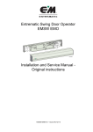
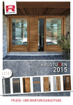
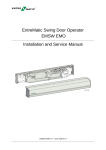
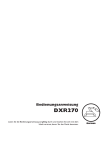
1003870
SW
TB2
1 2 3 4
D TB2,
ALLCLTABS1SAN
2 SUPPLY
MAX. 24 V
0 V DC
24 V DC
MVI Impulse
Outer Impulse
Lock 24 V DC
0 V DC
Key Impulse
Kill
MVI H.O.T
TB2
4
H.O.T
3
Motor control
0 V DC
"Slave"
24 V DC
2
Kill jumper
MVI N.O. / N.C.
MVI Open Lock / Door
Lock w. / w.o. power
Lock time 1.5 s / until closing
Slave delay off / on
Master / Slave
Push & Go
1
ON
Opening Delay
LK
HSC
LSC
HSC
LSC
LK
701448
LSO
HSO
LSO
HSO
701500
Entrematic Swing Door Operator
EMSW
Ruko DA501
14
1 1213
9 101
7 8
5 6
1 2 3 4
5 6 7 8
TM
Installation and Service Manual Original instructions
1004291-EMEI-5.0 – Issue 2012-01-26
© All rights in and to this material are the sole property of Ditec Entrematic Nordic AB. Copying, scanning, alterations or
modifications are expressly forbidden without the prior written consent of Ditec Entrematic Nordic AB. Rights reserved
for changes without prior notice.
Backtrack information: folder: Library, version: a317, date: 2012-01-26, time: 07:22:37, state: Working
CONTENTS
CONTENTS
1
Revision ............................................................................................................................... 4
2
Important information ........................................................................................................... 5
3
Technical specifications ....................................................................................................... 7
4
How the EMSW works ......................................................................................................... 9
5
Models ................................................................................................................................. 14
6
Part identification & Accessories ......................................................................................... 16
7
Pre-Installation ..................................................................................................................... 21
8
Mechanical installation ......................................................................................................... 24
9
Electrical connection ............................................................................................................ 39
10 Start-Up ............................................................................................................................... 45
11
Cover ................................................................................................................................... 48
12 Signage ................................................................................................................................ 50
13 Installation on fire doors ....................................................................................................... 51
14 Installation and adjustments - Low Energy Operator ........................................................... 56
15 Installation instructions for Accessories ............................................................................... 60
16 Troubleshooting ................................................................................................................... 66
17 Maintenance plan ................................................................................................................ 67
1004291-EMEI-5.0
Issue 2012-01-26
3
1 Revision
1
Revision
Following pages have been revised:
Page
Revision 4.0 → 5.0
New illustration on the front page
4
5
Module texts updated
7
Technical specification updated
11
10 sec changed to 14 sec.
12
Error messages added
45
New sentence
21
New chapter
51
Text updates, new sub section, new illustration
15, 40, 41, 42,
43, 47, 50
Illustrations updated
18
New cable kit
66
Troubleshooting about flashing LED added
55
Illustration updated
53
New section
18
Cable inlet added
18
Middle piece kit added
49
Middle piece cover added
27
Section updated. New installation instructions.
44
New section
Issue 2012-01-26
1004291-EMEI-5.0
2 Important information
2
Important information
Failure to observe the information in this manual may result in personal injury
or damage to equipment.
Save these instructions for future reference.
2.1
Intended use
The door is designed to offer continuous use, a high degree of safety and maximum lifetime.
The Entrematic EMSW is an automatic swing door operator developed to facilitate entrances
to buildings and within buildings through swing doors. The EMSW is an electrohydraulic operator approved for fire door applications. It is to be installed indoors where it is suitable for almost
all types of external and internal swing doors. This widely-used operator can be found on applications ranging from handicapped-access in private homes to high-traffic retail operations.
Door operator used in escape routes shall be installed so that the door opens in the escape direction unless the system allows breakout in this direction.
These operators shall be connected to a fire alarm system, see section 10.1, 13.2 or 13.3.
The motor, oil pump and hydraulic unit are combined into a compact unit mounted alongside
the control unit within the cover. The operator is connected to the door leaf with a range of
different arm systems.
For use see User manual 1004131.
2.2
Safety precautions
Do not climb on door parts.
Do not let children play with the door or the fixed controls.
Be sure to complete the site acceptance test before taking the door into operation, see PRA0007.
To avoid bodily injury, material damage and malfunction of the product, the instructions contained in this manual must be strictly observed during installation, adjustment, repairs and service
etc. Training is needed to carry out these tasks safely. Only Entrematic-trained technicians
should be allowed to carry out these operations.
2.3
Electronic equipment reception interference
The equipment complies with the European EMC directive (US market FCC Part 15), provided
installed according to Installation and Service manual.
The equipment may generate and use radio frequency energy and if not installed and used
properly, it may cause interference to radio, television reception or other radio frequency type
systems.
If other equipment does not fully comply with immunity requirements interference may occur.
However, there is no guarantee that interference will not occur in a particular installation. If
this equipment does cause interference to radio or television reception, which can be determined
by turning the equipment off and on, the user is encouraged to try to correct the interference by
one or more of the following measures:
• Re-orient the receiving antenna.
1004291-EMEI-5.0
Issue 2012-01-26
5
2 Important information
• Relocate the receiver with respect to the equipment.
• Move the receiver away from the equipment.
• Plug the receiver into a different outlet so that equipment and receiver are on different branch
circuits.
• Check that protective earth (PE) is connected.
If necessary, the user should consult the dealer or an experienced electronic technician for additional suggestions.
2.4
Environmental requirements
Entrematic products are equipped with electronics and may also be equipped with batteries
containing materials which are hazardous to the environment. Remove this material from the
operator before it is scrapped and make sure that it is disposed of properly as was done with the
packaging.
This manual contains the necessary details and instructions for the installation, maintenance
and service of the Swing Door Operator Entrematic EMSW.
6
Issue 2012-01-26
1004291-EMEI-5.0
3 Technical specifications
3
Technical specifications
Ensure that the door operator with technical specification below is suitable for the installation.
Manufacturer:
Ditec Entrematic Nordic AB
Address:
Lodjursgatan 2, SE-261 25 Landskrona, Sweden
Type:
EMSW
Mains power supply:
230 V AC ±10%, 50 Hz, mains fuse max 10A
Note! The mains power supply shall be installed with protection and an all-pole
mains switch with isolating capability of Category III, at least 3 mm between
contacts, shall be installed according to local regulations. These articles are not
provided with the door.
Power consumption:
Max. 230 W (Max 460 W Double door set)
Auxiliary voltage:
24 V DC, 700 mA (stabilized)
Motor fuse F1:
6,3 AT
Control fuse F2:
250 mAT
Recommended max. door Arm system PUSH:
weight:
250 kg for door leaf width 1600 mm
Arm system PULL / PULL-P:
100 kg for door leaf width 1400 mm
The EMSW complies with the door weights/widths stated in the:
Controlled door closing, EN 1154 Table I, size 3-6
Coordination unit for rebated doors, EN 1158
Türschliesser mit Öffnungsautomatik (Drechflügelantrieb), DIN 18263-4 AU
Grösse 3-6
Safety requirements:
In compliance with DIN 18650–1/2
Ambient temperature:
-15°C to +30°C
Relative humidity (noncondensing):
max. 85%
Dimensions:
Length: EMSW (standard cover) 716 mm
EMSW-SPEC 750-1600 mm
EMSW-2 1435-3200 mm
Height: 110 mm
Depth: 110 mm
Degree of protection:
IP 20
Degree of protection, con- IP54
trol actuators:
Approvals:
1004291-EMEI-5.0
Third party approvals from established certification organizations valid for safety
in use, see Manufacturer's declaration.
Issue 2012-01-26
7
3 Technical specifications
This product is to be installed internally.
13
110
80
110
38
298
8
Issue 2012-01-26
1004291-EMEI-5.0
4 How the EMSW works
4
How the EMSW works
The EMSW works electro-hydraulically. It opens with an AC-motor that via a hydraulic unit
and an arm system transmits the power to the door leaf. The closing power is from a coil spring.
The movement of the door is controlled by limit switches and valve screws.
4.1
Opening
When an opening impulse is received by the control unit, the motor starts and the hydraulic unit
rotates the drive shaft and arm system (door) with high speed towards open position. Before
fully open position, the speed is reduced to low speed. The door stops and the motor rotation
ceases when the selected door opening angle is reached. This open position is kept by a hydraulic
valve.
4.2
Closing
The spring closing starts when the hold open time has run out. Before fully closed position the
speed is reduced to low speed, which will be kept until the door is completely closed. The door
is kept closed by spring power. To overcome the resistance of a striking plate a “lock kick” can
be adjusted to required level.
4.3
Functions on the Control Unit CSDB
4.3.1
Key Impulse
Key impulse will open the door in programme selection OFF, EXIT and AUTO and keep the
door open during key hold open time.
Key hold open time can be adjusted between 0-30 sec.
4.3.2
Outer Impulse
Outer impulse will open the door if programme selection is AUTO and keep the door open
during the outer hold open time, which can be adjusted between 0-30 s.
4.3.3
Multi Voltage Input (MVI)
MVI impulse accepts a potential-free contact or 6-24 V AC/DC.
Status of lock (operation mode) can be selected via a function selector FS2 and depends on input
TB2:11 and 13.
FS-2 = OFF /factory setting)
FS-3 = OFF (factory setting)
TB2:11 and 13
CSDB (No PS)
TB2:11 and 13
6-24 V AC/DC*
AUTO
EXB OFF
EXB EXIT
TB2:11 and 13
OFF
OFF
EXIT
EXB AUTO
AUTO
EXB OPEN
OPEN
1004291-EMEI-5.0
Issue 2012-01-26
9
4 How the EMSW works
FS-2 = ON
TB2:11 and 13s TB2:11 and 13 TB2:11 and 13
FS-3 = OFF (factory setting)
6-24 V AC/DC*
CSDB (No PS)
AUTO
EXB OFF
OFF
EXB EXIT
EXIT
EXB AUTO
AUTO
EXB OPEN
OPEN
FS-2 = OFF (factory setting)
FS-3 = ON
TB2:11 and 13
OFF
TB2:11 and 13
TB2:11 and 13
6-24 V AC/DC*
CSDB (No PS)
OFF
Open door
EXB OFF
OFF
Open door
EXB EXIT
EXIT
Open door
EXB AUTO
AUTO
Open door
EXB OPEN
OPEN
Open door
FS-2 = ON
FS-3 = ON
TB2:11 and 13
TB2:11 and 13
TB2:11 and 13
6-24 V AC/DC*
CSDB (No PS)
Open door
OFF
EXB OFF
Open door
OFF
EXB EXIT
Open door
EXIT
EXB AUTO
Open door
AUTO
EXB OPEN
Open door
OPEN
* +6-24 V DC must be connected to TB2:13 and MVI jumper must be removed.
Programme selector must not be connected to TB2:13 if input is 6-24 V. Connect instead programme selector to EXB.
MVI impulse will unlock the lock and open the door or only unlock the lock (changes the operation mode of the operator). Can be selected via the function selector FS3.
MVI hold open time can be adjusted between 0-30 sec.
4.3.4
Kill Input
When kill is activated, the door will close immediately if not already closed. Hold open and
low pass filter timers are reset.
Key impulse will open lock during activated kill if not connected to TB2:5 for 0 V DC.
When kill is deactivated, the door will act according to current input status.
Several kill inputs are possible to connect in parallel with other CSDB control units. Connect
kill on the first operator according to the connection diagram. The second, third etc. operator
is only to be connected in parallel, from terminal 5 to 5 and 6 to 6.
Kill function is selected via a function selector (Kill jumper).
As an alternative to the shown connection under “Connection of activation units and accessories” on page 47, an alarm loop 24 VDC can be connected to the CSDB connect +24 VDC to
terminal 6 and 0 VDC to terminal 5.
10
Issue 2012-01-26
1004291-EMEI-5.0
4 How the EMSW works
4.3.5
Limit Switch Open
The limit switch indicates a fully open door and can be adjusted for opening angles up to 120º.
When the limit switch is activated the motor will stop. If the limit switch is not activated, the
motor will stop after 14 sec.
If the limit switch is deactivated when the door is open, the motor will restart to reposition the
door.
The LED indicates an activated limit switch.
Contact rating: 1A, 48 V DC, normally open.
4.3.6
Home Switch (optional)
When no home switch is mounted and the limit switch is deactivated in open position, a timer
starts and after 6 sec the status will change from closing to closed door.
If the optional home switch is mounted, this will indicate closed door instead of the timer.
“Opening delay” for lock (0-3s) is ignored as soon as home switch is not activated.
“Slave delay” (0,5s) is ignored as soon as home switch for the master is not activated.
Presence impulse is ignored when home switch indicates a closed door within 6 seconds.
The LED indicates an activated home switch.
4.3.7
Lock Output
The lock output is short circuit proof and can source a lock with 24V, 375 mA.
The output can be locked with power or locked without power. It can be selected via a function
selector (Locked w. / w.o. power).
The lock activation time can be either 1,5 s + (opening delay) or until closing. It can be selected
via a function selector (Lock time 1,5 s/until closing).
“Opening delay” for lock, the time that will pass before the motor starts, can be adjusted from
0-3 s.
If a home switch is installed, the lock opening time will first start when the home switch is deactivated. This to prevent door to jam in the lock, if presence detection is activated.
4.3.8
Double Door
The CSDB works as the master in a double door application and is connected to the slave unit
CSDA-S.
The slave unit has a standard opening delay of 0,2 sec. The delay can be increased to 0,5 sec.
to prevent jamming of thicker door leaves. This can be selected via a function selector (Slave
Delay). Home switch is recommended to prevent delay during closing.
When there is a need for more power supply than a single CSDB can deliver, a second CSDB
can be connected as a slave. The CSDB on the slave unit must then be configured as a slave.
This can be selected via a function selector (Master / Slave).
To enable only one door to open, connect impulse parallel on both units. Slave door must have
CSDB+EXB and the low pass filter potentiometer adjusted.
4.3.9
Push to Go
A push on the door will, from closed position, start an automatic opening cycle if the programme
selection is AUTO or EXIT and remain open during the hold open time “Outer HOT” (0-30 s).
1004291-EMEI-5.0
Issue 2012-01-26
11
4 How the EMSW works
A home switch on the operator is needed to achieve Push to Go. Can be selected via a function
selector (Push to Go).
The LED indicates when the home switch is active.
4.3.10
Error Messages
The LED indicates:
• Sensor error; 1 flash of 0,2 sec and then 1 sec pause etc.
• Lock error (too high current draw or short circuit); 1 flash of 0,2 sec and then 0,2 sec pause
etc.
• CSDB defect; 3 or 4 flashes of 0,2 sec and 0,2 pause
• No slave connected and Slave monitoring jumper is missing; 7 flashes of 0,2 sec and 0,2
pause
• Slave connected but Slave monitoring jumper is not removed; 7 flashes of 0,2 sec and 0,2
pause
• Defect slave CSDA-S; 7 flashes of 0,2 sec and 0,2 pause
• Old slave connected and Slave monitoring jumper removed; 7 flashes of 0,2 sec and 0,2
pause
4.3.11
Programme Selector
A programme selector PS-3B, with three positions OFF-AUTO-OPEN, can be connected to the
CSDB.
Note! If the MVI-input is used for 6-24 V, the PS-3B can not be used.
The key impulse is still valid in programme selection OFF.
Presence sensors are enabled in all programme selector settings but not when kill is active.
4.4
Functions on the Extension Unit EXB
4.4.1
Inner Impulse
Inner impulse will open the door if programme selection is AUTO or EXIT and keep the door
open during the hold open time.
The hold open time is adjustable from 0-30 sec.
4.4.2
Low Pass Filter (automatic cycle delay)
This function demands a constant inner impulse for a certain time to start an automatic cycle.
The time can be adjusted from 0-5 sec.
During closing the door will reopen immediately if impulsed.
4.4.3
Presence Impulse
Presence impulse will prevent an open door from closing and will re-open a closing door and
the control will make sure that the hold open time is not shorter than 1,5 s.
Presence impulse is ignored when home impulse is active.
Presence impulse is not a valid impulse if the door is manually opened.
Presence impulse is a valid impulse if the door is opened with Push to Go.
The input can be either “normally open” or “normally closed”, which can be selected via a
function selector (Presence Impulse NO/NC).
12
Issue 2012-01-26
1004291-EMEI-5.0
4 How the EMSW works
4.4.4
Presence Detection
Presence Detection will prevent a closed door from opening and stop an opening door.
A blank out switch is used to blank out the sensor from seeing for instance a wall close to the
open door. There can be two switches overlapping each other for the master door and two for
the slave door.
Two LED’s indicate the blank out switch status. One LED for the master door and one for the
slave door. The LED will light up if either of the two blanking switches is activated.
Presence detection can be selected via two function selectors, “Presence Detect Master” and
“Presence Detect Slave”.
4.4.5
Sensor Monitoring
Test of Presence detection is performed before opening. Test of Presence impulse is performed
before closing. The master sensors are tested first and the slave sensors are tested when the answer
is received from master sensors.
If sensor test is not performed successfully the door will enter manual mode and report sensor
error. The sensor test will continue during manual mode.
If no slave operator is present, when sensor monitoring is enabled, the “presence impulse slave”
should be connected to “sensor test slave”.
It is only possible to monitor sensors with output of type normally closed (NC).
If the sensor error disappears during manual mode the door will re-enter automatic mode again.
Monitoring can be selected via a function selector (Presence Sensor Monitoring).
4.4.6
Overhead Presence Detection (OPD)
OPD impulse will prevent a closed door from opening and an open door from closing.
A moving door will ignore the OPD input. The OPD will be active 6 sec. after the door has
started to close. If a home switch is mounted, the OPD will be active as soon as the door is
closed.
OPD can be selected via a function selector (Sensor type OPD/Mat).
4.4.7
Mat Safety
Mat safety impulse will prevent a closed door from opening and an open door from closing.
No impulses are accepted during closing if mat is activated.
Mat safety can be selected via a function selector (Sensor type OPD/Mat).
4.4.8
LockOut
LockOut is used to ignore the OPD sensor during opening and closing. Output will be low when
the door is considered closed, high during opening and open and toggling when the door is
closing.
LockOut output will be low when the door is manually opened.
4.4.9
Programme selector
Programme selector PS-4C can be connected to the EXB.
The PS-4C, compared to PS-3B, has a fourth position EXIT that will make the CSDB ignore
the outer impulse device.
Presence sensors are enabled in all programme selector settings but not when kill is active.
1004291-EMEI-5.0
Issue 2012-01-26
13
5 Models
5
Models
Three main models of the Entrematic EMSW are available:
• EMSW, standard cover
• EMSW-SPEC, cover with optional length
• EMSW-2, double door operators
The operators are non-handed and not dependent on the hinges. The operators suit both pushing
and pulling arm systems.
5.1
EMSW, standard cover (wall or door leaf mounted)
EMSW is the standard operator. Pushing arm system on a wall-mounted and on a door leafmounted operator shown.
Wall mounted
AAD174
Door leaf mounted
ILL-01652
14
Issue 2012-01-26
1004291-EMEI-5.0
5 Models
5.2
EMSW-SPEC, cover with optional length (wall mounted)
The EMSW-SPEC carries a cover with optional length e.g. with the same width as the door.
The length L must be specified in the order.
Pushing arm system shown.
L
AAD175
5.3
EMSW-2, double door operators (wall mounted)
The EMSW-2 consists of two operators that are mounted under the same cover to open one
door each. The length L must be specified in the order.
Pushing and pulling arm system shown. It is also possible to use two pushing or two pulling
arm systems.
L
AAD724
1004291-EMEI-5.0
Issue 2012-01-26
15
6 Part identification & Accessories
6
Part identification & Accessories
CL2
7
6
CL1
11
5
8
3
2
LSO
HSO
HSO
LK
LSC
HSC
HSC
15
LK
LSC
701448
LSO
701500
1
10
12
4
14
1
H.O.T
Kill
MVI H.O.T
Lock 24 V DC
TB2
Opening Delay
1003870
TB2
1 2 3 4
Motor control
0 V DC
"Slave"
24 V DC
SW
Kill jumper
MVI N.O. / N.C.
MVI Open Lock / Door
Lock w. / w.o. power
Lock time 1.5 s / until closing
Slave delay off / on
Master / Slave
Push & Go
4
0 V DC
Key Impulse
3
0 V DC
24 V DC
MVI Impulse
Outer Impulse
2
ON
TB2,
TB1 AND
ALLCLASS
2 SUPPLY
MAX. 24 V
14
1 1213
9 101
7 8
5 6
1 2 3 4
5 6 7 8
11
9
13
TM
6.1
No.
Description
No.
Description
1
Mounting plate
10
Extension unit, EXB (option)
2
Motor/pump
11
End plate
3
Magnetic valve
12
Programme selector, PS-3B (option)
4
Hydraulic unit
13
Cover
5
Drive shaft
14
Bearing sleeve
6
Spring tube
15
Cable holder
7
Cable inlet
CL1= Centre line, drive shaft
8
Mains connection
CL2= Centre line, hinge
9
Control unit, CSDB
Arm systems, PUSH / PUSH-325
PUSH: Art. No. 1003576BK
PUSH-325: Art. No. 1007134BK
These arm systems are delivered with drive arm, telescopic part and
door fitting.
They are used if the operator is installed on the wall on the opposite
side of the door swing and approved for fire door applications.
6.2
Arm system, PULL
PULL
Art. No. 1003577BK
This arm system is delivered with drive arm, guide shoe and door
fitting.
It is used if the operator is installed on the wall on the same side as
the door swing, i.e. the door is pulled open.
AAE346
16
Issue 2012-01-26
1004291-EMEI-5.0
6 Part identification & Accessories
6.3
Arm system, PULL-P
Art. No. 1005273BK
This arm system is delivered with drive arm, guide shoe and door
fitting with break-out unit.
It is used if the operator is installed on the wall on the same side as
the door swing and break-out unit is required.
6.4
Arm system, ST-V / ST-H
Art. No.: ST-V 172313
Art. No.: ST-H 172315
This arm system is delivered with drive arm and guide roller.
It is used if the operator is installed on the wall on the same side as
the door swing and break-out unit is required.
Note! Door fitting not included.
6.4.1
Options for ST-V / ST-H
Door fitting standard
Art. No.: 172071
Door fitting Break-out
Art. No. 172325 for pivot (break-out) door, right when the reveal A = 0-60 mm (0-2 3/8”) or
left when A > 60-100 mm (>2 3/8”-3 15/16”) for ST-H/ST-V
Art. No. 172327 for pivot (break-out) door, right when A > 60-100 mm (>2 3/8”-3 15/16”) or
left when A = 0-60 mm (0-2 3/8”)
Arm extension
Art. No. 172320 required when the reveal A >60-100 mm (>2 3/8”-3 15/16”)
1004291-EMEI-5.0
Issue 2012-01-26
17
6 Part identification & Accessories
6.5
Further accessories
4-Position Switch
(with EXB)
PS-4C
2-Position Switch
PSW-2
3-Position
Switch PS-3B
PSK-2
Extension unit
EXB
0
0
1
1
Art. No. 1004116
ILL-01578
Art. No.
655845
Art. No.
655843
Coordination unit, COOA
Art. No. 100091
Art. No. 1004117
Art. No.
655844
PULL-Arm Reveal Spacer
Art. No. 173804BK for PULL
Art. No. 173831BK for PULL-P
Middle piece kit
Art. No. 1008385
60 mm
(2-23/64")
40 mm (1-37/64")
Push & Go (PAG)
Finger protection strips
Art. No. 833333
Art. No. 833334
Art. No. 600149
Cable kit slave
PCB Attachment plate
Door stop
1
2
3
4
SW
Art. No. 656064
Art. No. 1003884
Art. No. 100147
18
Issue 2012-01-26
1004291-EMEI-5.0
6 Part identification & Accessories
PUSH, Arm Extensions
Cable inlet
Art. No. 1007567
Reveal
Extension
0-110 mm
Up to 4-3/8”
None
(Standard
arm)
110-235 mm
4-3/8” to 91/4”
345 mm
235-360 mm
9-1/4” to 141/8”
230 mm +
Joint part
Art. No.
-
-
173005
173004
+
173191
+
360-485 mm 345 mm +
14-1/8” to 19” Joint part
+
173005
+
173191
+
Drive Shaft Extension Kits
Control unit, CSDA-F
Art. No. 600081
70 mm
(2-3/4")
50 mm
(2")
20 mm
(3/4")
Drilling template
Art. No. 1000219
Art. No.
173107
Art. No.
173107
Tool kit to change rotation direction
Art. No. 173719
Cut-out in cover incl. smoke detector
ORS 142, socket and necessary screws
(cover not included)
Art. No. 173840
1004291-EMEI-5.0
Art. No.
173107
Restore after alarm button
Art. No. 600090
Limit Switch
Art. No. 655614 (L = 500 mm)
Art. No. 1004205 (L = 2000 mm)
Smoke Detector ORS 142
Art. No. 738794
Issue 2012-01-26
19
6 Part identification & Accessories
Ceiling socket 143A
for smoke detector
Art. No. 738795
Mounting plate
Ceiling socket 143W
for smoke detector
Art. No. 738795
Door mounting kit
(for door leaf mounted operators)
Art. No. 100132
Shaft extension, SEK
(including bearing for extension 70-420
mm)
Art. No. 173039
L
H
T Art. No.
(mm) (mm) (mm)
State
6.6
125
6
173680
160
8
173661
8x
2x
Labels
Label kit - including all below
Art. No. 1005227
Emergency break-out, DIN right door
Art. No. 1001785
Emergency break-out, DIN left door
Art. No. 1001786
Click!
Activation by disabled people
Art. No. 1003963
Operator designed for disabled people
Art. No. 1003964
Supervision of child
Art. No. 1001695
20
Issue 2012-01-26
1004291-EMEI-5.0
7 Pre-Installation
7
Pre-Installation
7.1
General tips/Safety concerns
• For enhanced security and vandalism protection, always mount the operator access in the
interior of a building whenever possible.
• Make sure that the power is off before installing.
• Make sure that the door leaf and the wall are properly reinforced at the installation points.
• Inspect the door hinges before installation to ensure that they are in good repair.
• Unpack the operator and make sure that all parts are delivered in accordance with the packing
note.
7.2.1
Operator handing
Right hand
Left hand
Left hand
Right hand
Pull
Push
7.2.2
Door handing (Automatic Door Industry)
Door handing is determined by standing with your back to the hinges. The side to which the
door normally opens (right or left) is the “handing” of the door. The diagram below shows a
right-handed door.
1004291-EMEI-5.0
Issue 2012-01-26
21
7 Pre-Installation
7.3
Fastening requirements
Always make sure, before commencing the installation, that the door leaf and the wall are
properly reinforced at the fixing points.
Also check the mechanical condition of the door that it is correctly balanced and opens and
closes properly.
Base material
Minimum requirements of wall profile
Steel
5 mm *
Aluminium
6 mm *
Reinforced concrete
min. 50 mm from the underside
Wood
50 mm
Brick wall
Expansion shell bolt, min. M6x85, UPAT PSEA B10/25, min. 50 mm
from the underside
* Thinner wall profiles must be reinforced with rivnuts
7.4
Tools required
•
•
•
•
7.5
Torx T8, T10, T20 and T25
Metric hexagonal key 3, 4 and 6 mm
Flatblade screwdriver, small
Torque wrench with metric Allen socket 6 mm
Installation on double doors
If the operators are to be mounted at the same height with pushing and pulling arm systems, the
height is determined by the pulling arm system, PULL/ST. The pushing arm system PUSH must
always have a shaft extension, minimum 50 mm.
Example: If PULL has a 20 mm extension, the PUSH must have a 70 mm extension.
For installation follow the instructions for the applicable arm system.
22
Issue 2012-01-26
1004291-EMEI-5.0
7 Pre-Installation
7.6
Installation examples for fire approved doors
Illustrations below show examples of approved reinforcements when mounting a fireproof swing
door operator.
Note! The type approval for fireproof swing doors is valid only with the arm system PUSH.
Reveal max 480 mm and shaft extension max 50 mm.
3
1
2
2
Min.
45
5
Min.
45
4
6
2
9
7
8
8
No.
Description
No.
Description
1
Steel min. 50x5, L=min. 100, centered for mounting
holes (4x)
This is a requirement with aluminium profiles.
Screw M6, FS-TT FZB, Taptite, L=40 (4x)
6
Wood screw M6, KST, L=45 (2x)
2
Steel min. 50x5, L=min. 150, centered at the arms length 7
on the door.
This is a requirement with aluminium profiles.
Screw M6, FS-TT FZB, Tabtite, L=40 (2x)
Rivnut M6, FTT/ST, L=15,9 (4x)
Screw M6, FS-TT FZB Tabtite, L=40 (4x).
Rivnuts are only allowed to be used with steel profiles
with thickness of min 1,5 mm.
3
Steel min. 50x5, L=min. 100, centered for mounting
holes (4x)
This is a requirement with aluminium profiles.
Screw M6, FS-TT FZB, Tabtite, L=50 (4x) Distance
piece ø10/13
8
Rivnut M6, FTT/ST, L=15,9 (2x)
Screw M6, FS-TT FZB, Tabtite, L=40 (2x).
Rivnuts are only allowed to be used with steel profiles
4
Expansion-shell bolt (4x)
(for brickwall min. M6x85, UPAT PSEA B 10/25)
9
Rivnut M6, FTT/ST, L=15,9 (4x)
Screw M6, FS-TT FZB, Tabtite, L=50 (4x)
Distance piece ø10/13.
Rivnuts are only allowed to be used together with a
plasterboard beam made of steel with a material thickness of min 1,5 mm.
5
Wood screw M6, KST, L=min. 70 (4x)
Distance piece ø10/13
1004291-EMEI-5.0
Issue 2012-01-26
23
8 Mechanical installation
8
Mechanical installation
This instruction comprises the installation of the Entrematic EMSW with arm systems PUSH,
which push the door open and PULL / ST-V/H, which pull the door open. See also “QuickStart”
which is enclosed with each operator.
8.1
Wall mounted operator with arm system PUSH
X
Y
2 – 17
48
20
2 – 37
68
50
2 – 67
98
70
2 – 87
118
Y
X
13
80
13
CL 2
0-110
CL 1
Y
X
1
(485)
45
248
364
217
102
X
2
Drilling template
Art. No. 1000219
ø 5,1 mm, 8x
24
Issue 2012-01-26
1004291-EMEI-5.0
8 Mechanical installation
Cont. “Wall mounted operator with arm system PUSH”
CL 1
15
25
3
ø 16 mm
(Cable inlet hole)
CL 2
CL 1
210
4
LK
HSC
HSC
LSC
LSC
LK
701448
LSO
LSO
HSO
HSO
701500
5
CL 2
CL 1
LK
6
HSC
HSC
LSC
LSC
LK
701448
LSO
LSO
HSO
HSO
701500
2x
1004291-EMEI-5.0
Issue 2012-01-26
25
8 Mechanical installation
Cont. “Wall mounted operator with arm system PUSH”
7
Adjust +/– 1 tooth = ±5°
7a
7b
90°
IIIIIIIII
I
8
9
II
III
25 Nm
I
60
90°
26
Issue 2012-01-26
1004291-EMEI-5.0
8 Mechanical installation
8.2
Door leaf mounted operator EMSW E with arm system PUSH-325
108,5 108,5
245
45
2
180
CL
1
210
max. 135
CL
2
max. 135
min. 50
min.
min.45
45
3
min.
min.120
120
3
110
80
13
17
48
min. 50
0
716
0
1
110
CL1
Pivot or butt hinges
CL2
Operator drive shaft
1
Cable inlet at end plate
2
Door mounting kit, Art. No.
100132, optional
3
Reinforcements required in door
leaf and at the fixing holes
1004291-EMEI-5.0
Issue 2012-01-26
27
28
Issue 2012-01-26
30 34
701448
LSO
HSO
LSO
HSO
(1 3/16") (1 11/32")
HSC
LSO
701500
701500
5
LSC
LSO
HSO
HSO
LK
HSC
LSC
HSC
LSC
LK
HSC
LSC
HSC
LSC
LK
701448
701448
LSO
HSO
LSO
HSO
LSO
HSO
LSO
HSO
701500
701500
3
HSC
LSC
701448
LK
HSC
LSC
HSC
LSC
LK
701448
LSO
HSO
LSO
HSO
LK
LK
HSC
LSC
HSC
LSC
701448
LSO
HSO
LSO
HSO
34 30
(1 11/32") (1 3/16")
LK
701500
701500
1
LK
HSC
LSC
HSC
LSC
8.3.1
LK
8.3
LK
LK
8 Mechanical installation
Wall mounted operator with arm system PULL, PULL-P and ST
Note! If the operator is not ordered for pulling arm system, the direction of rotation must be
reversed.
Changing the direction of rotation
2
165˚
4
6
ILL-01556
1004291-EMEI-5.0
8 Mechanical installation
8.3.2
Installation of operator with arm system PULL
13
80
CL 2
Top of door
23
Z
13
Z
≤ 60
_
46
20
66
50
96
70
116
40 x 60
(turnable)
1
23
Z
CL 1
582
109
364
217
102
Z
2
ø 5,1 mm, 8x
1004291-EMEI-5.0
Issue 2012-01-26
Drilling template
Art. No. 1000219
29
8 Mechanical installation
Cont. “Installation of operator with arm system PULL”
CL 1
15
25
3
ø 16 mm
(Cable inlet hole)
CL 2
CL 1
210
LK
HSC
LSC
LK
HSC
LSC
4
701448
LSO
LSO
HSO
HSO
701500
6x
CL 2
5
CL 1
LK
HSC
LSC
LK
HSC
LSC
701448
LSO
LSO
HSO
HSO
701500
Connect mains power
5 6
9 10
78
13 14
11 12
30
Issue 2012-01-26
TB2,
TB1 AND
ALLCLASS
2 SUPPLY
MAX. 24 V
Lock 24 V DC
0 V DC
24 V DC
MVI Impulse
Outer Impulse
0 V DC
Key Impulse
Kill
T
/ Door
ower
closing
/ on
l
TB2
1004291-EMEI-5.0
8 Mechanical installation
Cont. “Installation of operator with arm system PULL”
6
CL 2
7
LK
HSC
LSC
LK
HSC
LSC
701448
LSO
LSO
HSO
HSO
701500
2x
CL 2
HSC
701448
8
LSO
HSO
LSO
HSO
701500
CL 2
9
III
IIIIIIIIIIII
I
25 Nm
I
1004291-EMEI-5.0
Issue 2012-01-26
31
8 Mechanical installation
Cont. “Installation of operator with arm system PULL”
10
LK
HSC
LSC
LK
HSC
LSC
701448
LSO
LSO
HSO
HSO
701500
5 6
9 10
78
13 14
11 12
TB2,
TB1 AND
ALLCLASS
2 SUPPLY
MAX. 24 V
Lock 24 V DC
0 V DC
24 V DC
MVI Impulse
Outer Impulse
0 V DC
Key Impulse
Kill
T
ck / Door
ower
closing
f / on
control
TB2
Click
11
LK
HSC
LSC
LK
HSC
LSC
701448
LSO
LSO
HSO
HSO
701500
Click
32
Issue 2012-01-26
1004291-EMEI-5.0
8 Mechanical installation
8.3.3
Installation of operator with arm system ST
A = 0 - 60
A > 60 - 100 (Optional)
61
13
80
CL 2
40
Top of door
A
CL 1
2x
40
61
1
Outside open door
364
217
81
102
2
61
Drilling template
Art. No. 1000219
1004291-EMEI-5.0
ø 5,1 mm, 6x
Issue 2012-01-26
33
8 Mechanical installation
Cont. “Installation of operator with arm system ST”
Outside open door
96
25
3
ø 16 mm (Cable inlet hole)
Outside open door
CL 2
4
291
LK
HSC
HSC
LSC
LSC
LK
701448
LSO
LSO
HSO
HSO
701500
6x
34
Issue 2012-01-26
1004291-EMEI-5.0
8 Mechanical installation
Cont. “Installation of operator with arm system ST”
CL 2
5
LK
HSC
LSC
LK
HSC
LSC
701448
LSO
LSO
HSO
HSO
701500
5 6
9 10
78
13 14
11 12
TB2,
TB1 AND
ALLCLASS
2 SUPPLY
MAX. 24 V
Lock 24 V DC
0 V DC
24 V DC
MVI Impulse
Outer Impulse
0 V DC
Key Impulse
Kill
T
701500
control
LSO
ck / Door
ower
closing
TB2
Connect mains power
CL 2
LK
6
HSC
LSC
LK
HSC
LSC
701448
LSO
LSO
HSO
HSO
701500
143
7
1004291-EMEI-5.0
Issue 2012-01-26
35
Lock 24 V DC
9 10
TB2,
TB1 AND
ALLCLASS
2 SUPPLY
MAX. 24 V
78
0 V DC
24 V DC
MVI Impulse
Outer Impulse
5 6
0 V DC
Key Impulse
701500
Kill
HSC
LSC
LK
701448
LSO
Issue 2012-01-26
MVI H.O.T
III
I
IIIIIIIIIIII
25 Nm
MVI Open Lock / Door
Lock w. / w.o. power
Lock time 1.5 s / until closing
Slave delay off / on
LK
HSC
LSC
LSO
36
HSO
10
HSO
"Slave" control
8 Mechanical installation
Cont. “Installation of operator with arm system ST”
CL 2
8
I
9
13 14
11 12
TB2
10a
0º
10c
10b
≈ 45º
≈ 90º
1004291-EMEI-5.0
8 Mechanical installation
Cont. “Installation of operator with arm system ST”
11
LK
HSC
HSC
LSC
LSC
LK
701448
LSO
LSO
HSO
HSO
701500
=
=
12
LK
HSC
HSC
LSC
LSC
LK
701448
LSO
LSO
HSO
HSO
701500
310
210
Break-out
1004291-EMEI-5.0
Issue 2012-01-26
37
8 Mechanical installation
Cont. “Installation of operator with arm system ST”
13
LK
HSC
LSC
LK
HSC
LSC
701448
HSO
LSO
LSO
HSO
701500
2x
ø 5,1 mm, 2x
LK
14
HSC
LSC
LK
HSC
LSC
701448
LSO
LSO
HSO
HSO
701500
2x
38
Issue 2012-01-26
1004291-EMEI-5.0
9 Electrical connection
9
Electrical connection
Note! During any work with the electrical connections the mains power must be disconnected.
9.1
Control units
The operator can be equipped with different control units adapted to the functions required.
9.1.1
CSDB
This basic control unit is equipped with inputs for connection of automatic and manual activation
units such as radars, photocells, normal push buttons, emergency push buttons etc. Electromechanical striking-plate and slave control unit CSDA-S for double doors can be connected.
9.1.2
CSDA-S
This slave control unit is used together with CSDB for double doors as explained above.
9.1.3
EXB
This extension unit is mounted on top of the CSDB to extend the CSDB functions with inputs
for presence impulse, presence detection, inner impulse, off and exit.
9.1.4
CSDA-F
This unit is, together with CSDB, mainly used for fire doors. Electro-mechanical striking-plate
24 V AC can be connected.
1004291-EMEI-5.0
Issue 2012-01-26
39
9 Electrical connection
9.2
Connection of control unit CSDB – single doors
Connect the mains power to the mains terminal block.
Note! Accessories and activation units must not be connected until the adjustment of speeds
etc. has been carried out.
Note! It is important that the high and low voltage cables are well separated and fixed. The high
voltage cables must be routed and fixed on one side of the drive unit by using the enclosed cable
holders and the low voltage cables must be
routed on the opposite side using the same type of cable holders.
F2 = 250
250 mAT
mAT
F2=
Limit switch open
F1=
F1 =6,3ATH
6,3 ATH
Home switch
HSC
LSC
LK
LK
LSC
Opening valve
N
1
Kill
Lock 24 V DC
1003870
MVI H.O.T
TB2
Opening Delay
H.O.T
TB2
1 2 3 4
Motor control
0 V DC
"Slave"
24 V DC
SW
Kill jumper
MVI N.O. / N.C.
MVI Open Lock / Door
Lock w. / w.o. power
Lock time 1.5 s / until closing
Slave delay off / on
Master / Slave
Push & Go
4
0 V DC
Key Impulse
3
0 V DC
24 V DC
MVI Impulse
Outer Impulse
2
ON
TB2,
TB1 AND
ALLCLASS
2 SUPPLY
MAX. 24 V
7 8
5 6
L
Mains power
230 V AC - 50 Hz, 10A
14
1 1213
9 101
1 2 3 4
5 6 7 8
Slave monitoring jumper 3)
TB1
1
2
3
4
S
W
40
TB2
H.O.T
MVI H.O.T
Opening Delay
ON
TB2
MVI / Key HOT
1
FS
Opening delay
Outer HOT
FS
1
2
3
4
5
6
7
8
Motor control
0 V DC
Slave control
24 V DC
Slave feed back
Watchdog
(–)
(+)
(–)
(+)
Kill Kill + 1)
0 V DC
Key Impulse
Lock
24 V DC, 375 mA
0 V DC
24 V DC
max. 700 mA
ON
TB2
5
6
7
8
9
10
11
12
13
14
1 2 3 4
Sensor Monitoring
OFF / ON
LED
Kill jumper
MVI N.O. / N.C.
MVI Open Lock / Door
Lock w. / w.o. power
Lock time 1.5 s / until closing
Slave delay off / on
Master / Slave
Push & Go
1003870
TB2
TB1
Motor control
0 V DC
"Slave"
24 V DC
MVI Jumper 2)
Kill jumper
MVI NO / NC
MVI Open Lock / Door
Locked w. / wo. power
Locked tome 1.5 s until closing
Slave delay off / on
Master / Slave
Push to Gp
1) See page 47 when connecting "Kill"
2) If 6-24 VDC on TB2: 11-13, remove jumper
3) Remove jumper when connecting ta slave CSDA-S
(but not when connecting to slave CSDB).
MVI Impluse
Outer Impluse
Issue 2012-01-26
1004291-EMEI-5.0
9 Electrical connection
9.3
Connection of control units CSDB and CSDA-S – double doors
For double door operators, both operators have to be connected to the mains. A four-pole cable
(enclosed) has to be connected between TB1 on the CSDB and TB6 on the CSDA-S.
Note! It is important that the high and low voltage cables are well separated and fixed. The high
voltage cables must be routed and fixed on one side of the drive unit by using the enclosed cable
holders and the low voltage cables must be routed on the opposite side using the same type of
cable holders.
Motor control
0 V DC
Slave control
24 V DC
Slave feed back
Watchdog
1
2
3
4
S
W
CSDA-S
Limit switch
open
TB6
SW
3 4
1 2
LK
HSC
HSC
LSC
LSC
LK
TB6
701448
Opening valve
F2
250 mAT
mAT
F2==250
F1 =6,3
6,3AT
ATH
F1=
L
N
F2
F1
Mains power
230 V AC - 50 Hz,10A
CSDB
1
2
3
4
SW
N
ON
H.O.T
Lock 24 V DC
TB2,
TB1 AND
ALLCLASS
2 SUPPLY
MAX. 24 V
0 V DC
Key Impulse
0 V DC
24 V DC
MVI Impulse
Outer Impulse
Kill
MVI H.O.T
L
Mains power
TB2
Opening Delay
1003870
TB2
Motor control
0 V DC
"Slave"
24 V DC
1 2 3 4
Kill jumper
MVI N.O. / N.C.
MVI Open Lock / Door
Lock w. / w.o. power
Lock time 1.5 s / until closing
Slave delay off / on
Master / Slave
Push & Go
14
1 1213
9 101
7 8
5 6
230 V AC - 50 Hz, 10A
1 2 3 4
5 6 7 8
1
TB1
2
3
4
7 8
5 6
3 4
1 2
Kill jumper
MVI N.O. / N.C.
MVI Open Lock / Door
Lock w. / w.o. power
Lock time 1.5 s / until closing
Slave delay off / on
1003870
Motor control
0 V DC
"Slave"
24 V DC
ON
1 2 3 4
TB1
Motor control
0 V DC
Slave control
24 V DC
Slave feed back
Watchdog
TB2
1
2
3
4
S
W
SW
Slave monitoring
Jumper
ON
Remove jumper when connecting to slave CSDA-S
1004291-EMEI-5.0
Issue 2012-01-26
41
9 Electrical connection
9.4
Connection of control units CSDB/CSDB – double doors
For double door operators both operators have to be connected to the mains. A three-pole cable
(not enclosed) has to be connected between TB1 on the CSDB (master) and TB2 on the CSDB
(slave).
Note! It is important that the high and low voltage cables are well separated and fixed. The high
voltage cables must be routed and fixed on one side of the drive unit by using the enclosed cable
holders and the low voltage cables must be routed on the opposite side using the same type of
cable holders.
Door mounted sensors must be connected to it's own master and slave CSDB/EXB.
Adjust opening
delay to "0"
Adjust MVI / Key
Hot to "0"
7
5 6
1
CSDB
2
3
H.O.T
TB2
1003870
Motor control
0 V DC
"Slave"
24 V DC
SW
1 2 3 4
Kill jumper
MVI N.O. / N.C.
MVI Open Lock / Door
Lock w. / w.o. power
Lock time 1.5 s / until closing
Slave delay off / on
Master / Slave
Push & Go
4
e
Slav
FS-7 = ON
ON
FS
1 2 3
ON
7 8
5 6
3 4
1 2
9 10
7 8
5 6
3 4
1 2
LK
HSC
LSC
LK
LSC
HSC
701448
TB2
F2=
250
mAT
F2 =
250
mAT
F1=
ATATH
F1 6,3
= 6,3
5 6 7 8 9 10 1112 1314
L
N
Mains power
230 V AC - 50 Hz, 10A
Motor control
0 V DC
Slave control
24 V DC
Slave feed back
Watchdog
1
2
3
4
S
W
(–)
(+)
(+)
Kill Kill +
0 V DC
Key Impulse
Lock
24 V DC, 375 mA
0 V DC
24 V DC
MVI Impluse
Outer Impluse
max. 700 mA
TB2
TB1
F2
F1
ter
Mas
TB1
CSDB
1
2
3
4
SW
N
ON
H.O.T
Lock 24 V DC
0 V DC
Key Impulse
0 V DC
24 V DC
MVI Impulse
Outer Impulse
Kill
MVI H.O.T
TB2,
TB1 AND
ALLCLASS
2 SUPPLY
MAX. 24 V
230 V AC - 50 Hz, 10A
1 2 3 4
5 6 7 8
42
L
Mains power
TB2
Opening Delay
1003870
TB2
Motor control
0 V DC
"Slave"
24 V DC
1 2 3 4
Kill jumper
MVI N.O. / N.C.
MVI Open Lock / Door
Lock w. / w.o. power
Lock time 1.5 s / until closing
Slave delay off / on
Master / Slave
Push & Go
14
1 1213
9 101
7 8
5 6
Issue 2012-01-26
1004291-EMEI-5.0
9 Electrical connection
9.5
Connection of extension unit EXB – option
The extension unit EXB is to be installed on top of the CSDB.
HSC
HSC
LSC
LK
LK
LSC
701448
HSO
a Connect the flat cable on the EXB to the CSDB.
b Snap on the EXB to the CSDB.
ON
H.O.T
Lock 24 V DC
TB2,
TB1 AND
ALLCLASS
2 SUPPLY
MAX. 24 V
0 V DC
Key Impulse
0 V DC
24 V DC
MVI Impulse
Outer Impulse
Kill
MVI H.O.T
1314
11 12
TB2
Opening Delay
1003870
TB2
Motor control
0 V DC
"Slave" control
24 V DC
1 2 3 4
Kill jumper
MVI N.O. / N.C.
MVI Open Lock / Door
Lock w. / w.o. power
Lock time 1.5 s / until closing
Slave delay off / on
Master / Slave
Push & Go
9 10
7 8
5 6
Presence impluse configuration
NC / NO*
Blanking switch
Blanking switch
Presence detect Master
Presence detect Slave
Sensor type
OPD / MAT
Blanking LED
30 31
28 29
26 27
24 25
3
2
22
20 21
34
32 33
35 36
37
9 10
7 8
5 6
1
11 12
314
Y
Inner HOT
Presence detect Slave
Low pass filter
Presence impluse Slave
Presence detect Master
TB4
26 27 28 29 30 31 32
TB3
20 21 22 23 24 25
TB5
33 34 35 36 37
Presence impluse Master
24 V DC
Presence detect slave
Sensor test slave
Presence impulse slave
0 V DC
24 V DC
Lock out
OPD / MAT
Presence detect master
Sensor test master
Presence impulse master
0 V DC
24 V DC
EXIT
OFF
0 V DC
Inner impluse
0 V DC
* When selecting NO, remove both jumpers
for presence impulse Master and Slave.
Note! It is important that the high and low voltage cables are well separated and fixed. The high
voltage cables must be routed and fixed on one side of the drive unit by using the enclosed cable
holders and the low voltage cables must be routed on the opposite side using the same type of
cable holders.
1004291-EMEI-5.0
Issue 2012-01-26
43
9 Electrical connection
9.6
Sensor cable inlet
1
2
8
Alt. 11
Alt.
8
Alt. 22
Alt.
29
12
3
15,5
ø 3,7
44
4
5
6
7
Issue 2012-01-26
1004291-EMEI-5.0
10 Start-Up
10
Start-Up
Adjust the operator to have maximum 25% duty cycle, which means motor run time.
Give a short opening impulse by strapping the impulse input and adjust if necessary as follows.
See also illustration under Closing torque.
a Set the hold open time with the potentiometer on the control unit.
b Adjustment of the opening speed.
• Adapt the high speed opening HSO, to the existing traffic situation. Turning clockwise
decreases the speed.
• The low speed opening LSO, needs to be adjusted only if the door is extremely heavy.
Turning clockwise decreases the speed.
Note! If it is hard to obtain an even and smooth braking, the opening torque (pump pressure)
must be reduced.
c Adjustment of the closing speed.
• Adjust the low speed closing LSC as low as the traffic situation allows. Turning clockwise
decreases the speed.
• If a higher closing speed is required, open the high speed closing valve HSC (closed from
factory).
Note! If the installation requires adjustment of the closing torque follow the instructions on
“Closing torque” on page 45.
d Fine-adjust the opening angle by means of the limit switch. The limit switch is slid into a
groove in the hydraulic unit and tightened with a lock screw. By moving the limit switch
sideways, the opening angle is changed.
Note! To make the adjustment easier, the limit switch can be moved to the underside of the
hydraulic unit. Any of the grooves at the motor side of the outgoing shaft can be used.
e If an electromechanical striking plate is installed, an additional “lock-kick” can be obtained
during the last 5° of the closing cycle by adjusting the screw LK on the hydraulic unit. This
screw is normally closed. Adjust by opening the screw 90° and check the function.
Note! Opening the screw too much may delay the opening.
f Connect the activation units.
g Check that the installation complies with valid regulations and requirements from the authorities.
h Special care should be taken regarding entrapment between driven parts and surrounding
fixed parts.
10.1
Closing torque
To comply with authority requirements or to overcome over/under pressure the closing torque
can be adjusted.
The closing torque (spring force) is adjusted by means of an Allen screw placed at the end of
the spring tube. The end plate has to be dismantled. Turning the screw clockwise increases the
force. One turn equals a torque change of approx. 1 Nm (28 turns from min. to max.). The door
must be in open position when extremely low torque is adjusted.
1004291-EMEI-5.0
Issue 2012-01-26
45
10 Start-Up
10.2
Opening torque
If the closing torque (spring force) has been changed, or if the door does not open to its full
extent, the opening torque (pump pressure) must be adjusted as follows:
a The factory set torque for PUSH is 70 Nm and for PULL 40 Nm at a door opening angle of
0-2°.
b Measure the opening torque by using a spring balance and adjust if necessary.
The torque is adjusted by means of an Allen screw placed on the pump. Turning clockwise increases the opening torque/pump pressure. One turn equals a torque change of approx. 30 Nm.
PUSH = 70 N
PULL = 40 N
3 mm
LSO
5°
25
25
0
2
4
6
8
10
12
14
16
18
20
22
10 mm
0
2
4
6
8
10
12
14
16
18
20
22
HSO
POCKET
BALANCE
LK
3 mm
HSO
LSO
F
HSO
LSO
701500
LSC
701448
HSC
LK
LK
LSC
HSC
6 mm
F
POCKET
BALANCE
0
2
4
6
8
10
12
14
16
18
20
22
25
0
2
4
6
8
10
12
14
16
18
20
22
2 mm
25
HSC
5°
PUSH = 35 N
PULL = 20 N
46
LSC
Issue 2012-01-26
1004291-EMEI-5.0
10 Start-Up
10.3
Connection of activation units and accessories
AK / ES-P
PB…
6 - 24 V AC/DC
SR120-1
GND
R2
1 2 3
1 2 3 4
E C
D G
SR120-1
GND
R2
7 8
CSDB/TB2
7 13
CSDB/TB2
7 14
CSDB/TB2
12 11 8
1 2 3
EXB/TB4
1 2 3 4
12 1114
7 8
12 11 8
EXB/TB3 7201321
CSDB/TB2
CSDB/TB2
11 1211 8
B D
(+)
12 1114
1003909
11 13
1003921
MVI impulse
(+)
11 121114
1003921
Key impulse
1 2 3 4 5 6 7
Outer impulse
20 25 202111 13
Inner impulse
11 121114
32 26 30
EXB/TB3 20 21
4 SAFE
1003909
E EYE-TECH
F
11 1211 8
25 20 21
7 14
EYE-TECH
1 2 3 4 5 6 7
Bodyguard
A C
6 - 24 V AC/DC
AK / ES-P
PB…
CSDB/TB2
4 SAFE
(monitored)
(SuperScan)
Bodyguard
20 25 2021A
B
C
D
E
25 20 21
EXB/TB4
Red
Black
White
Green
32 26 30
31
Overhead presence detection OPD
31
Brown
F Blue
G Yellow
PS-3B
PS-4C
PS…-2
0
PS-3B
PS…-2
PS-4C
1
24 V DC
External − +
Alarm loop
24 V DC
− +
0
1
Kill1)
3)
1 2 3
2)
Auto/Open
Yellow
Black
CSDB/TB2
Red
EXB/TB3
CSDB/TB2
3)
8
8
7 13
7 13
1 2 3
7 8
7 8
1 2 3
Off/Auto
1 2 3
1 2 3 4 5
Off/Exit/Auto
/Open2)
1 2 3 4 5
11 13
11 13
Time switch 3),4)
(by others)
Kill1)
5
22 23 24 21 5
6
6
7 12
7 12
11 13
11 13
ILL-00573
EXB/TB3
22 23 24 21
ILL-00573
1) Set FS-1 to OFF, when connecting “Kill”
2) Set FS-2 to ON
3)If PS-3B and “Time switch”, connect “Time Switch” in serial to TB2:13
4)Switching is dependent on Key HOT
1004291-EMEI-5.0
Issue 2012-01-26
47
11 Cover
11
Cover
The cover and mounting plate are manufactured in clear anodized aluminium. The end plates
are made of a black self-extinguishing plastic material.
11.1
Fitting and removing the cover
Break off and snap on the fill cover into the mounting plate for output shaft.
Snap on the other fill cover for the second slot.
The cover is slid over flanges in the end plates and fixed to the underside of
the mounting plate with one screw for earth connection.
Stick the Entrematic logotype to the cover – see below.
LSO
HSO
HSC
HSC
LSC
LK
LK
LSC
701448
HSO
2
LSO
701500
If properly installed and adjusted, attach the product label, which includes
the CE mark.
1
H.O.T
Kill
MVI H.O.T
Lock 24 V DC
TB2
Opening Delay
1003870
TB2
1 2 3 4
Motor control
0 V DC
"Slave"
24 V DC
SW
Kill jumper
MVI N.O. / N.C.
MVI Open Lock / Door
Lock w. / w.o. power
Lock time 1.5 s / until closing
Slave delay off / on
Master / Slave
Push & Go
4
0 V DC
Key Impulse
3
0 V DC
24 V DC
MVI Impulse
Outer Impulse
2
ON
TB2,
TB1 AND
ALLCLASS
2 SUPPLY
MAX. 24 V
14
1 1213
9 101
7 8
5 6
1 2 3 4
5 6 7 8
1
TM
3
1
1 Fill cover (2 pcs)
2 End plate
3 Earth/Fastening screw
48
Issue 2012-01-26
1004291-EMEI-5.0
11 Cover
11.2
Middle piece cover
X
4
4
X-8
X
(4)
1004291-EMEI-5.0
Cover
Cover
Issue 2012-01-26
49
12 Signage
Signage
XXXXXXX
ART. NO.
XXXXXXX
XXXX
TYPE
XXXXXX
PROJECT
SERIAL NO.
YEAR+WEEK
XXX
VAC
XXX
A
XXX
W
XX/XX
Hz
1 2 3 4 5 6 7 8
A
XX
CLASSIFICATION DIN 18650
SITAC1422
EN ISO 9001 Certificate No: 911828, 956538
xxxxxxxxx
1002
SÜD
xxxxxxxxxxxxx
xxxxxxxxxxxxx
1004197
Landskrona Sweden
Factory No. 1
12
B
Click!
D
E
F
Click!
800 mm
C
If problem occurs
Action
Check that all required signage is applied and intact. Mandatory indicates that the signage is required by European
directives and equivalent national legislation outside the European Union.
A
Product label: Mandatory
B
Emergency break-out: Mandatory, if approved for escape route.
C
D
E
F
50
Entrematic door sticker: Mandatory, if applicable to highlight the presence of the glass (applied to all glass
sections that are moving).
Supervision of child: Mandatory, if applicable (applied to both sides of the door). To be placed on entrances
where the risk analysis shows use by children, elderly and disabled.
Operator designed for disabled people:
Recommended, if applicable (applied to both sides of the door)
Activation by disabled people: Recommended, if applicable
Issue 2012-01-26
1004291-EMEI-5.0
13 Installation on fire doors
13
Installation on fire doors
• The Entrematic EMSW is approved in accordance with DIN 18263-4 for use on fire doors.
The approval covers compliance with EN1154 Table 1, sizes 3-6, for use on fire doors with
controlled door closing. For size 3 max door leaf weight is 60 kg and max door leaf width
is 950 mm. For size 6 max door leaf weight is 120 kg and max door leaf width is 1400 mm.
• For rebated double doors the coordination unit COOA, which is an accessory integrated in
the EMSW, can be used. The COOA is in compliance with EN1158, which guarantees for
a correct closing order both after manual and automatic openings.
• The EMSW can be connected to the overriding fire alarm central and, if required, emergency
push buttons for door closing can be installed locally. When the signal is broken, an opening
or open door will immediately close.
• The Arm System PUSH must be used.
13.1
Control unit CSDA-F (option)
For a more advanced solution, a special control unit CSDA-F can be installed alongside the
basic control unit CSDB. This unit can be used as a central for required detectors, manual push
button for closing etc. It also secures that the automatic door opening function will not be restored
after alarms from detectors or after manual door closing. To restore the automatic door operation
each door must receive a separate restoring signal.
The connection of CSDA-F can be carried out in two ways:
• For automation of fire doors without overriding fire detection and alarm system.
• For automation of fire doors with overriding fire detection and alarm system.
Different connection examples are shown on “Automation of fire doors without overriding fire
detection and alarm system” on page 54 and “Automation of fire doors with overriding fire
detection and alarm system” on page 55.
Cover length (with CSDA-F)
Single door operators L = 865-1600 mm
Double door operators L = 1560-3200 mm
1004291-EMEI-5.0
Issue 2012-01-26
51
13 Installation on fire doors
13.1.1
Connection of control unit CSDA-F – single door
Note! It is important that the high and low voltage cables are well separated and fixed. The high
voltage cables must be routed and fixed on one side of the drive unit by using the enclosed cable
holders and the low voltage cables must be routed on the opposite side using the same type of
cable holders.
CSDA-F
Kill jumper
MVI NO / NC
MVI Open Lock / Door
Locked w. / wo. power
Locked tome 1.5 s until closing
Slave delay off / on
Master / Slave
Push to Gp
ON
1 2 3 4 5 6 7 8
Alarm output, NO
Alarm output, NC
Alarm output, COM
TB2
2)
Restore after alarm button
Lock
(+)(–)(+)
N L
Mains power and earth to CSDA-S if used
Kill +
0 V DC
Key Impulse
(–)
2)
24 V DC, alarm loop after detectors
0 V DC, detectors
24 V DC, detectors, Max 75 mA
Kill -
5 6 7 8 9 1011121314
2)
Close door button, normally closed
1 2
TB4
0 V DC, Lock output
0 V AC, Lock output
24V AC/DC1), Lock output
1 2 3 4 5 6 7 8 9 10 11 12
TB1
1 2 3 4 5
TB2
CSDB
FS
24 V DC, 375 mA
Max.700 mA
0 V DC
24 V DC
MVI Impluse
Outer Impluse
1)
Restore after alarm button with
mains indicator.
Art. No. 600090
CSDA-F
Brown
24V AC, 850 mA, 1,5 s 24V DC,
850 mA
EXB
TB3
2)
Remove jumper when connecting
to terminal
Green
White
5
3 4
1 2
678
20 21 22 23 24 25
112
9 101
3)
Note!
Fixed jumper on EXIT,
TB3: 22-24
TB1
TB4
Set FS-1 to OFF when connecting
to Kill
F1= 6,3 AT
F3=250 mAT
F2=250 mAT
F4=250 mAT
F5=250 mAT
AC
DC
TB3
ON
H.O.T
Lock 24 V DC
TB2,
TB1 AND
ALLCLASS
2 SUPPLY
MAX. 24 V
0 V DC
Key Impulse
0 V DC
24 V DC
MVI Impulse
Outer Impulse
Kill
MVI H.O.T
N
1314
11 12
L
Mains power
230 V AC - 50 Hz, 10A
TB2
Opening Delay
1003870
TB2
0 V DC
"Slave" control
24 V DC
1 2 3 4
Kill jumper
MVI N.O. / N.C.
MVI Open Lock / Door
Lock w. / w.o. power
Lock time 1.5 s / until closing
Slave delay off / on
Master / Slave
Push & Go
9 10
7 8
5 6
1 2 3 4
5 6 7 8
52
11
9 10
7 8
5 6
3 4
1 2
AAE277
AAE277
AAE277
B
9
7 8
5 6
12
TB1
DA-F
Issue 2012-01-26
TB2
Motor control
FS
1003870
CS
TB4
CSDA
TB1
Close
Alarm loop
0 V DC, detectors
24 V DC, detectors
Restore alarm
Alarme NO
Alarme NC
Alarme COM
1 2
TB1
0 V DC, Lock
0 V AC, Lock
Lock 24 V AC/DC
CSDA
TB1
TB2
TB2
Lock
TB3
DC
1 2 3 4 5
CSD
4
AC
5
3
5 6
34
1112
2
12
9 10
7 8
5 6
3 4
1 2
1004291-EMEI-5.0
13 Installation on fire doors
13.1.2
Connection of control unit CSDA-F – double door
Mains
Mains
CSDB
CSDA-F
CSDA-S
14
1213
1
Kill
Lock 24 V DC
1003870
TB2
H.O.T
MVI H.O.T
Motor control
0 V DC
"Slave"
24 V DC
TB2
AAE277
1 2 3 4
Kill jumper
MVI N.O. / N.C.
MVI Open Lock / Door
Lock w. / w.o. power
Lock time 1.5 s / until closing
Slave delay off / on
Master / Slave
Push & Go
SW
ON
Opening Delay
4
1 2 3 4
5 6 7 8
CSDA
TB1
112
9 101
7 8
5 6
3 4
1 2
0 V DC
Key Impulse
3
5
0 V DC
24 V DC
MVI Impulse
Outer Impulse
2
34
TB2,
TB1 AND
ALLCLASS
2 SUPPLY
MAX. 24 V
9 1011
7 8
5 6
12
Mains
Mains
“Master”
"Master"
“Slave”
"Slave"
1314
11 12
1
13.1.3
H.O.T
Kill
MVI H.O.T
Lock 24 V DC
N
L
TB2
1003870
TB2
Motor control
0 V DC
"Slave"
24 V DC
Opening Delay
ON
1 2 3 4
5 6 7 8
CSDA
TB1
1 2 3 4
1112
AAE277
SW
9 10
7 8
5 6
3 4
1 2
Kill jumper
MVI N.O. / N.C.
MVI Open Lock / Door
Lock w. / w.o. power
Lock time 1.5 s / until closing
Slave delay off / on
Master / Slave
Push & Go
4
5
0 V DC
Key Impulse
3
34
0 V DC
24 V DC
MVI Impulse
Outer Impulse
2
12
TB2,
TB1 AND
ALLCLASS
2 SUPPLY
MAX. 24 V
9 10
7 8
5 6
Mains power
230V AC - 50 Hz, 10A
Function check
Check that the systems works:
•
•
•
•
Connect the mains.
Give a reset on "Restore after alarm button".
Give impuls on terminal 7-8 on CSDB.
Cut the jumper terminal 10-12 on CSDA-F during the opeing cycle.
•
•
•
•
Make sure that opening cycle is interupted and that the door closes.
Give a new opening impulse - the operator shall not open.
Connect the jumper (or the alarm loop) between terminal 10-12.
Give a reset on "Restore after alarm button".
Give a new impulse and the door shall make a new open/close cycle.
1004291-EMEI-5.0
Issue 2012-01-26
53
13 Installation on fire doors
13.2
Automation of fire doors without overriding fire detection and alarm
system
13.2.1
General connection
For this type of installation the required fire detectors are direct-connected to the CSDA-F.
CSDA - F
Alarm
6
9
+24 V
8
1
TB1
9
4
Potential free contact alarm
6
8
BN
BN
10
NO
COM
F4
250 mAT
4
1200 Ohn
BN
BN
LED green
4
Close door button
Power consumption max. 25 mA
Smoke detector
Restore after alarm button
CSDA - F
CSDA - F
F4
F4
250 mAT
+24 V
250 mAT
+24 V
TB1
TB1
10
10
4
4
4
4
4
4
4
Power consumption max. Power consumption max.
25 mA
25 mA
4
4
4
Power consumption max. Power consumption max.
Power consumption max.
25 mA
25 mA
25 mA
Option with 3 smoke
detectors
Option with 2 smoke
detectors
54
4
Issue 2012-01-26
1004291-EMEI-5.0
13 Installation on fire doors
13.3
Automation of fire doors with overriding fire detection and alarm
system
This connection is only possible if the fire alarm system has a potential free breaking contact.
To make the fire doors close on an alarm, the contact must open. Required fire detectors are to
be connected to the alarm system. A push button for manual door closing can be connected to
each door. The number of fire doors that can be connected to the breaking contact in the alarm
system depends on the breaking capacity of the contact.
The capacity of the fire alarm system power supply is calculated according to the number of
CSDA-F used x 0,05 A.
13.3.1
Connection of CSDA-F to a fire alarm system
Fire alarm system (by others)
CSDA-F # 1
Potential free contact
with breaking capacity.
12
11
10
-
24 VDC
+
CSDA-F # 2
12
11
10
CSDA-F # n
12
11
10
1004291-EMEI-5.0
Issue 2012-01-26
55
14 Installation and adjustments - Low Energy Operator
14
Installation and adjustments - Low Energy Operator
To limit entrapment force and push opening force, parameters to work with are pump pressure,
opening and closing time, spring tension and the way the PUSH arm system is mounted. The
PULL arm system is standard mounted.
All force measurements are made at the door handle approx. 25 mm from the leading edge.
a Install the operator as to the manual but the PUSH arm system door adaptor should be moved
50 mm further out from the hinges (illustration 1).
b Adjust the spring closing force to desired value but max 67 N. The door must be in open
position when adjusting. It is only necessary to measure the force in open position were the
force is highest.
c Adjust the closing time from 90-0º (illustration 2), on the LSC valve only (fully close the
HSC valve). See diagram for opening and closing time.
d
e
f
g
h
Note! Add 2 seconds for latch check.
Check that max manual opening force does not exceed 90 N. It is only necessary to measure
the force in open position were the force is highest.
Adjust the pump opening force to max 67 N in closed position.
Adjust the back check (illustration 3), on the LSO valve, to 2 seconds.
Adjust the opening time from 0-80º (approx. 200 mm from full open position, see illustration
3), on the HSO valve. See diagram for opening and closing time.
Adjust the hold open time, on the potentiometer, to desired value but minimum 5 seconds
1
300 mm
45 mm
200 mm
2s
t+2
>3 s
12
9
12
3
9
6
2
14.1
3
6
3
Complementary Safety Devices Swing Doors
If there is any risk for finger jam, add finger protection strip at the hinge side for internal doors,
article No. 833334 or add finger protection roll for external doors, article No. 833333.
56
Issue 2012-01-26
1004291-EMEI-5.0
14 Installation and adjustments - Low Energy Operator
14.2
Swing Doors Opening and Closing Time
Adjust, as a minimum, the operator's opening and closing time according to the diagram below.
14.2.1
How to find the correct opening and closing time
• Measure the door width.
• If the door weight is unknown, follow the instructions in “Diagrams for door weight”.
• Go into the diagram below to find the correct minimum opening/closing time “t”.
Example: If the door width is 1.1 m and the door weight is 50 kg the minimum opening and
closing time will be ~3,5 seconds.
Minimum Swing Door Opening/Closing Time, t
for LE Compliance [s]
6
Door Weight
100 kg
90 kg
80 kg
5
70 kg
60 kg
50 kg
4
40 kg
30 kg
3
0,7
0,8
0,9
Door Width in metres
1
1,1
1,2
1,3
Example
14.3
Diagrams for Door weight
a Measure the door width (DW) and the door height (DH) in metres for one door leaf only.
b Calculate the area DW x DH
c Select diagram for your type of door and the actual glass thickness. Find the weight.
Example: Aluminium door with measurement DW = 1.5 m, DH = 2 m and glass thickness 12
mm. Calculate 1.5 x 2 = 3 m2. Look into the first diagram for “Aluminium Frame with glass”.
Start with the area and follow the line up to the 12 mm glass, go left to receive the door weight
95 kg.
Note! The weights can vary depending on the door design (the table shows only typical values).
1004291-EMEI-5.0
Issue 2012-01-26
57
14 Installation and adjustments - Low Energy Operator
14.3.1
Aluminium frame with glass
Door leaf weight [kg]
200
8/24/8 glass
190
180
170
12 mm glass
6/10/6 glass
160
150
140
10 mm glass
130
120
110
8 mm glass
100
90
80
6 mm glass
70
60
50
40
30
20
1
2
3
Example
14.3.2
4
5
Door leaf area [m2]
Steel frame with glass
Door leaf weight [kg]
200
190
180
170
160
10 mm glass
150
140
130
120
8 mm glass
110
100
90
6 mm glass
80
70
60
50
40
30
20
1
2
3
4
5
2
Door leaf area [m ]
58
Issue 2012-01-26
1004291-EMEI-5.0
14 Installation and adjustments - Low Energy Operator
14.3.3
Solid wood
Door leaf weight [kg]
60 mm
wood
200
190
180
50 mm
wood
170
160
150
40 mm
wood
140
130
120
110
30 mm
wood
100
90
80
20 mm
wood
70
60
50
40
30
20
1
2
3
4
5
Door leaf area [m2]
1004291-EMEI-5.0
Issue 2012-01-26
59
15 Installation instructions for Accessories
15
Installation instructions for Accessories
15.1
COOA - Coordination unit
15.1.1
EMSW 2 - Push
B
A
5-6
3
6
C
C
2
oor
LSO
HSC
LSC
LK
LSC
5
HSC
701448
LSO
701500
e" d
HSO
v
"Sla
HSO
6
7
LK
1
1
4
ste
"Ma
or
r" do
6
5
“Master”
LK
HSC
HSC
LSC
LSC
LK
6
701448
LSO
LSO
HSO
HSO
4
701500
2
8
min.
14
m (5
06 m
5.3"),
. 32
max
m (1
00 m
26")
“Slave”
1 Hook bracket
4 Cable strap
7 Return spring
2 Lever bracket
5 Balance spring
8 Follow roller (carry bar)
3 Wire wheel
6 Plastic hose
Installation of coordination unit
The brackets 1 2 are to be mounted to the pump flange on the ”master” door operator and the
wire wheel 3 to the drive shaft on the ”slave” door operator.
Note! If the ”master” and ”slave” doors are interchanged, the brackets are to be fitted to the
underside of the pump flange.
Fit the hook bracket 1 to the pin in the pump flange and screw the bracket tight.
Fit the lever bracket 2 onto the hooks on the hook bracket 1 including return spring 7 .
Install the wire through the plastic hoses 6 and fix to the motor screws with cable straps 4 .
Mount the wire wheel 3 on the ”slave” door operator using screw and washer. The wheel
is to be mounted in accordance with fig. A or B depending on which door being the ”slave”
door. Always on top of the operator.
e Close the doors and mount the wire in the lever bracket 2 and in the wire wheel 3 with the
spring 5 pre-tensioned approx. 10 mm. Open the ”master” door and let it hook up. Adjust
the spring tension (loosen the wire) so that the ”master” door starts to close with normal
speed.
f Adjust the closing time to approx. 6 seconds.
g Mount the follow roller (carry bar) 8 according to illustration.
h Give opening impulse and check the function.
a
b
c
d
60
Issue 2012-01-26
1004291-EMEI-5.0
15 Installation instructions for Accessories
15.1.2
EMSW 2 - Pull
B
A
5-6
3
6
C
C
LSO
HSC
HSC
LSC
LK
6
LK
7
LSC
701448
HSO
6
LSO
701500
2
HSO
1
5
4
5
1
2
LK
HSC
HSC
LSC
LSC
LK
701448
LSO
LSO
HSO
HSO
4
701500
180
in. 1
mm
m
min.
15/3
1406
mm
26")
m (1
00 m
x. 32
ma
.3"),
7/16")
(55
ve"
r
doo
"Sla
or
" do
ster
"Ma
(46
, ma
2")
09
m (1
80 m
x. 27
6
"Slave"
"Master"
1 Hook bracket
4 Cable strap
2 Lever bracket
5 Balance spring
3 Wire wheel
6 Plastic hose
7 Return spring
Installation of coordination unit
The brackets 1 2 are to be mounted to the pump flange on the ”master” door operator and the
wire wheel 3 to the drive shaft on the ”slave” door operator.
Note! If the ”master” and ”slave” doors are interchanged, the brackets are to be fitted to the
underside of the pump flange.
Fit the hook bracket 1 to the pin in the pump flange and screw the bracket tight.
Fit the lever bracket 2 onto the hooks on the hook bracket 1 including return spring 7 .
Install the wire through the plastic hoses 6 and fix to the motor screws with cable straps 4 .
Mount the wire wheel 3 on the ”slave” door operator using screw and washer. The wheel
is to be mounted in accordance with fig. A or B depending on which door being the ”slave”
door. Always on top of the operator.
e Close the doors and mount the wire in the lever bracket 2 and in the wire wheel 3 with the
spring 5 pre-tensioned approx. 10 mm. Open the ”master” door and let it hook up. Adjust
the spring tension (loosen the wire) so that the ”master” door starts to close with normal
speed.
f Adjust the closing time to approx. 6 seconds.
g Give opening impulse and check the function.
a
b
c
d
1004291-EMEI-5.0
Issue 2012-01-26
61
15 Installation instructions for Accessories
15.2
PAG
2 mm
Alternative PC-board fixing
hole depending on mounting
side and if "Push" or "Pull"
CSDB
TB2
Remove screw before installing
A
PC-board fixing and
adjustment screw
5 6 7 8 9 10 1112
14
Black
Green
Red
Hall-switch
A
A–A
X
Magnet
Adjustment of impulse sensitivity
α
α
0
X
Important notice!
To avoid bodily injury, the opening time from closed to fully open door must not be less than
4 seconds.
If door stop is mounted on operator, PAG can be mounted on opposite side.
62
Issue 2012-01-26
1004291-EMEI-5.0
15 Installation instructions for Accessories
15.3
Door stop
LK
HSC
LSC
LK
HSC
LSC
701448
HSO
LSO
LSO
HSO
701500
min. 2 mm (2/32")
• Install door stop to top side of output spindle to prevent door from extending beyond 90º.
• Mount door stop when door is in open position with a clearance of 2 mm (2/32") as shown
below.
Fine adjust, if necessary, on limit switch and/or on armsystem.
1004291-EMEI-5.0
Issue 2012-01-26
63
15 Installation instructions for Accessories
15.4
Armsystem PULL-P
8
11
8
7
1
16
13
12
ø 9,5 (3/8")
16
10
9
4
3
5
1
A
15
8
B
2
3
6
5
8
CL
C
14
15
15
15
15
65
109* (4
15.4.1
19/ ")
64
(2 9/16")
65
623 (24
(2 9/16")
17/ ")
32
1
Short slide track
7
Door stop
13 End caps
2
Long slide track
8
Rubber absorber
14 Flexible steel hose FLS
3
Ball catch
9
Magnetic switch G1
15 Fastening hole (4 pcs)
4
Arm stop
10 Magnet
16 Lock screws
5
Ball seat
11 Crimp connectors
17 Reveal spacer (optional)
40 / 60 mm (1 37/64" / 2
23/64") Art. No. 173
831BK
6
Hinge
12 Drive arm
Mounting instruction for magnetic switch G1
To make sure that the operator is disconnected when the door is paniced a switch must be connected to kill.
a Drill a 9.5 mm (3/8") hole in the door leaf just behind the magnet for the magnetic switch
G1.
b Extend the cable length for the switch G1.
c Mount the magnetic switch G1 and the flexible steel hose FLS in accordance with the picture.
d Connect G1 to kill.
15.4.2
Installation of PULL-P
a Mark and drill the 4 fastening holes ø 4,6 (3/16") in the door leaf.
b Mount the two short slide tracks.
c Slide the hinge into the short slide track next to the door hinge and make sure they are aligned
(A). Secure with the lock screw.
d Slide the long slide track into the hinge and make sure they are aligned (B). Secure with the
lock screw.
e Slide the ball catch into the short slide track at the front of the door and make sure they are
aligned (C). Secure with the lock screw.
64
Issue 2012-01-26
1004291-EMEI-5.0
15 Installation instructions for Accessories
f Slide the arm stop into the long slide track. Position it close to the hinge and secure it with
the lock screw (will be adjusted later).
g Slide the drive arm with its guide shoe into the long slide track.
h Slide the ball seat into the long slide track. Make sure the magnet is facing the door.
i Close the slide track and press the ball seat against the ball catch. Secure with the lock screw.
j Mount the door stop on the ball seat.
k Fix the rubber absorber at the door frame behind the door stop.
l Adjust the spring pre-tension on the ball catch to its maximum and then release 2 turns.
m Mount the drive arm to the operator (see installation manual).
n Check break-out force with a balance by pulling the door into panic direction. Max force
must not be higher than 220 N (49 lbf). Adjust if necessary.
o Stick the rubber absorbers to the frame just behind the arm.
p Snap on the two end caps to the slide track.
Z
_
46 (1
13/ ")
16
20
66 (2
19/ ")
32
POCKET
BALANCE
0
2
4
6
8
10
12
14
16
18
20
22
0
2
4
6
8
10
12
14
16
18
20
22
25
25
25/ ")
32
50
96 (3
70
116 (4 9/16")
8
min. 30 (13/16")
23 (29/32")
Z
7
10
9
17
0 - 130 mm (5 3/32")
1004291-EMEI-5.0
Issue 2012-01-26
65
16 Troubleshooting
16
Troubleshooting
Fault
Possible reasons why
Remedies/Explanation
The door does not open Programme selector is set to OFF
- The motor does not start Motor power is missing
- The motor starts
Change setting
Check motor cable
Mains power is missing
Check power
Fuse has blown
Replace fuse
Activation unit does not function
Strap impulse inputs
Electric striking plate is binding
Adjust striking plate
Arm system has come loose
Readjust pre-tension and tighten arm system
The door does not open Limit switch opening has come loose
to required angle
Check limit switch
The door does not close Constant impulse is created
Disconnect activation unit or replace control unit
The door does not open Pump pressure is too low
fast enough
Adjust pump pressure
The door opens with too “Lock-kick” valve is opened too much
much delay
Adjust valve screw
No smooth braking dur- Pump pressure too high
ing operation
Low speed distance too short
Adjust pump pressure
Increase opening angle, or
increase pre-tension of arm system
High sound level
Motor in contact with mounting plate
Mount two extra screws at the motor side to seduce
the mounting plate to the wall
The door does not stay
open or cannot open
Magnetic valve out of operation
Check by pressing the pin on top of the magnetic
valve.
If the door stops, then check the resistance (should
be 150 ohm) for the wire between the magnetic valve
and the control unit.
3 or 4 flashing LED
CSDB default
Replace control unit
7 flashing LED
No slave connected and slave monitoring jumper is Replace jumper
missing
Slave connected but slave monitoring jumper is not Remove jumper
removed
66
CSDA-S defect
Replace contol unit
Old CSDA-S connected and slave monitoring removed
Replace jumper
Issue 2012-01-26
1004291-EMEI-5.0
17 Maintenance plan
17
Maintenance plan
Regular inspections shall be made according to national regulations by a trained and qualified
person. The number of service occasions shall be in accordance with national requirements.
This is especially important when the installation concerns a fire-approved door or a door with
an emergency opening function.
As with all other technical products, an automatic door needs maintenance and service. It is
essential to know the importance of maintenance to have a reliable and safe product.
Service and adjustments will ensure a safe and proper operation of an automatic door unit.
The table below shows the recommended interval, in months, when to replace parts during
preventive maintenance.
Cycles/hour in operation
Part
Part number
<10
<100
>100
Low Medium High
traffic traffic traffic
Abusive
Environment
Vibration absorbers and
oil plug
331003882
24
12
6
6
PUSH service kit
24
12
6
6
24
12
6
6
331003888
PULL/PULL-P service
kit
331003886
ST-V/H service kit
331003887
24
12
6
6
Limit switch
33655614
24
12
6
6
Capacitor
655599
60
60
60
60
CSDB-230 control unit
331004115
60
60
60
60
CSDA-S
600089
60
60
60
60
CSDA-F
600081
60
60
60
60
1004291-EMEI-5.0
Issue 2012-01-26
67
Ditec Entrematic Nordic AB, Box 669, SE-261 25 Landskrona, Sweden
Tel: +46 418 514 50 • Fax: +46 418 511 63
[email protected] • www.ementrematic.com