1
KA681/KA691/KA692/KA694 CPU
System Maintenance
Order Number: EK–498AB–MG. B01
Digital Equipment Corporation
Maynard, Massachusetts
August, 1994
Digital Equipment Corporation makes no representations that the use of its products in the
manner described in this publication will not infringe on existing or future patent rights, nor do
the descriptions contained in this publication imply the granting of licenses to make, use, or sell
equipment or software in accordance with the description.
Possession, use, or copying of the software described in this publication is authorized only
pursuant to a valid written license from Digital or an authorized sublicensor.
© Digital Equipment Corporation 1994. All Rights Reserved.
The postpaid Reader’s Comments forms at the end of this document request your critical
evaluation to assist in preparing future documentation.
The following are trademarks of Digital Equipment Corporation: CompacTape, CX, DDCMP,
DEC, DECconnect, DECdirect, DECnet, DECscan, DECserver, DECUS, DECwindows, DELNI,
DEMPR, DESQA, DESTA, DSRVB, DSSI, IVAX, KDA, KLESI, MicroVAX, MSCP, OpenVMS,
Q–bus, Q22–bus, RA, RQDX, RRD40, SDI, ThinWire, TK, TMSCP, TQK50, TQK70, TSV05,
TU, ULTRIX, UNIBUS, VAX, VAX 4000, VAX DOCUMENT, VAXcluster, VAXELN, VAXlab,
VAXserver, VAXsimPLUS, VT, and the DIGITAL logo.
All other trademarks and registered trademarks are the property of their respective holders.
S2651
This document was prepared using VAX DOCUMENT Version 2.1.
Contents
Preface . . . . . . . . . . . . . . . . . . . . . . . . . . . . . . . . . . . . . . . . . . . . . . . . . . . . .
xv
1 System Maintenance Strategy
1.1
1.2
1.3
1.4
Service Delivery Methodology . . . .
Product Service Tools and Utilities
Information Services . . . . . . . . . . .
Field Feedback . . . . . . . . . . . . . . . .
.
.
.
.
.
.
.
.
.
.
.
.
.
.
.
.
.
.
.
.
.
.
.
.
.
.
.
.
.
.
.
.
.
.
.
.
.
.
.
.
.
.
.
.
.
.
.
.
.
.
.
.
.
.
.
.
.
.
.
.
.
.
.
.
.
.
.
.
.
.
.
.
.
.
.
.
.
.
.
.
.
.
.
.
.
.
.
.
.
.
.
.
1–1
1–2
1–5
1–6
.
.
.
.
.
.
.
.
.
.
.
.
.
.
.
.
.
.
.
.
.
.
.
.
.
.
.
.
.
.
.
.
.
.
.
.
.
.
.
.
.
.
.
.
.
.
.
.
.
.
.
.
.
.
.
.
.
.
.
.
.
.
.
.
.
.
.
.
.
.
.
.
.
.
.
.
.
.
.
.
.
.
.
.
.
.
.
.
.
.
.
.
.
.
.
.
.
.
.
.
.
.
.
.
.
.
.
.
.
.
.
.
.
.
.
.
.
.
.
.
.
.
.
.
.
.
.
.
.
.
.
.
.
.
.
.
.
.
.
.
.
.
.
.
.
.
.
.
.
.
.
.
.
.
.
.
.
.
.
.
.
.
.
.
.
.
.
.
.
.
.
.
.
.
.
.
.
.
.
.
.
.
.
.
.
.
.
.
.
.
.
.
.
.
.
.
.
.
.
.
.
.
.
.
.
.
.
2–2
2–6
2–7
2–9
2–9
2–16
2–19
2–20
2–23
CPU and Memory Module Order . . . . . . . . . . . .
Installing Add-On MS690 Memory Modules
General Module Order for Q–Bus Options . . . . .
Recommended Module Order of Q-Bus Options .
(Optional) DSSI Ports Assignment . . . . . . . . . . .
Mass Storage Options (Internal) . . . . . . . . . . . .
System Expansion . . . . . . . . . . . . . . . . . . . . . . .
Mass Storage Expanders . . . . . . . . . . . . . . .
Q–Bus Expanders . . . . . . . . . . . . . . . . . . . .
Control Power Bus for Expanders . . . . . . . .
.
.
.
.
.
.
.
.
.
.
.
.
.
.
.
.
.
.
.
.
.
.
.
.
.
.
.
.
.
.
.
.
.
.
.
.
.
.
.
.
.
.
.
.
.
.
.
.
.
.
.
.
.
.
.
.
.
.
.
.
.
.
.
.
.
.
.
.
.
.
.
.
.
.
.
.
.
.
.
.
.
.
.
.
.
.
.
.
.
.
.
.
.
.
.
.
.
.
.
.
.
.
.
.
.
.
.
.
.
.
.
.
.
.
.
.
.
.
.
.
.
.
.
.
.
.
.
.
.
.
3–1
3–2
3–4
3–7
3–8
3–8
3–10
3–10
3–11
3–12
2 CPU System Overview
2.1
2.2
2.3
2.4
2.4.1
2.4.2
2.4.3
2.4.4
2.4.5
CPU Module Features . . . . . . . .
MS690 Memory Modules . . . . . .
(Optional) DSSI Daughter Board
BA440 Enclosure Components . .
H3604 Console Module . . . . .
System Control Panel (SCP)
BA440 Backplane . . . . . . . . .
Power Supply . . . . . . . . . . . .
System Airflow . . . . . . . . . . .
.
.
.
.
.
.
.
.
.
.
.
.
.
.
.
.
.
.
3 System Setup and Configuration
3.1
3.1.1
3.2
3.3
3.4
3.5
3.6
3.6.1
3.6.2
3.6.3
iii
3.6.4
3.7
3.7.1
3.8
3.8.1
3.8.2
3.8.3
3.8.3.1
3.8.3.2
3.8.3.3
3.8.3.4
3.8.3.5
3.8.3.6
3.8.3.7
3.8.3.8
3.8.3.9
3.8.4
3.8.4.1
3.8.4.2
3.8.5
3.8.5.1
3.8.5.2
3.8.5.3
Adding Options to the System Enclosure . . . . . . . . . . . . . . .
DSSI VAXclusters . . . . . . . . . . . . . . . . . . . . . . . . . . . . . . . . . . .
DSSI VAXcluster Configuration Rules . . . . . . . . . . . . . . . . .
Firmware Commands and Utilities Used in System
Configuration . . . . . . . . . . . . . . . . . . . . . . . . . . . . . . . . . . . . . . .
Examining System Configuration . . . . . . . . . . . . . . . . . . . . .
Using the CONFIGURE Command to Determine CSR
Addresses for Q–Bus Modules . . . . . . . . . . . . . . . . . . . . . . .
Setting and Examining Parameters for DSSI Devices . . . . .
DSSI Device Parameters . . . . . . . . . . . . . . . . . . . . . . . .
How the OpenVMS Operating System Uses the DSSI
Device Parameters . . . . . . . . . . . . . . . . . . . . . . . . . . . . .
Entering the DUP Driver Utility from Console Mode . .
Entering the DUP Driver Utility from the OpenVMS
Operating System . . . . . . . . . . . . . . . . . . . . . . . . . . . . .
Setting Allocation Class . . . . . . . . . . . . . . . . . . . . . . . . .
Setting Unit Number . . . . . . . . . . . . . . . . . . . . . . . . . . .
Setting Node Name . . . . . . . . . . . . . . . . . . . . . . . . . . . .
Setting System ID . . . . . . . . . . . . . . . . . . . . . . . . . . . . .
Exiting the DUP Driver Utility . . . . . . . . . . . . . . . . . . .
Write-Protecting an EF/RF ISE . . . . . . . . . . . . . . . . . . . . . .
Software Write-Protect for EF/RF-Series ISEs . . . . . . . .
Hardware Write-Protect for EF/RF ISEs . . . . . . . . . . . .
Setting System Parameters: Boot Defaults, Bootflags, Halt
and Restart Action . . . . . . . . . . . . . . . . . . . . . . . . . . . . . . . .
Setting the Boot Default . . . . . . . . . . . . . . . . . . . . . . . .
Setting Boot Flags . . . . . . . . . . . . . . . . . . . . . . . . . . . . .
Setting the Halt Action . . . . . . . . . . . . . . . . . . . . . . . . .
.
.
.
3–13
3–17
3–19
.
.
3–24
3–24
.
.
.
3–26
3–28
3–29
.
.
3–30
3–36
.
.
.
.
.
.
.
.
.
3–38
3–39
3–39
3–42
3–42
3–43
3–46
3–46
3–47
.
.
.
.
3–51
3–51
3–53
3–54
.
.
.
.
.
.
.
.
.
.
.
4–1
4–4
4–4
4–7
4–8
4–8
4–9
4–13
4–15
4–20
4–20
4 System Initialization and Acceptance Testing (Normal
Operation)
4.1
4.2
4.2.1
4.2.2
4.2.3
4.3
4.3.1
4.3.2
4.4
4.5
4.6
iv
Basic Initialization Flow . . . . . . . . . . . . . . . .
Power-On Self-Tests (POST) . . . . . . . . . . . . . .
Power-Up Tests for Kernel . . . . . . . . . . . .
Power-Up Tests for Q–Bus Options . . . . .
Power-Up Tests for Mass Storage Devices
CPU ROM-Based Diagnostics . . . . . . . . . . . .
Diagnostic Tests . . . . . . . . . . . . . . . . . . . .
Scripts . . . . . . . . . . . . . . . . . . . . . . . . . . .
Basic Acceptance Test Procedure . . . . . . . . . .
Machine State on Power-Up . . . . . . . . . . . . . .
Main Memory Layout and State . . . . . . . . . .
.
.
.
.
.
.
.
.
.
.
.
.
.
.
.
.
.
.
.
.
.
.
.
.
.
.
.
.
.
.
.
.
.
.
.
.
.
.
.
.
.
.
.
.
.
.
.
.
.
.
.
.
.
.
.
.
.
.
.
.
.
.
.
.
.
.
.
.
.
.
.
.
.
.
.
.
.
.
.
.
.
.
.
.
.
.
.
.
.
.
.
.
.
.
.
.
.
.
.
.
.
.
.
.
.
.
.
.
.
.
.
.
.
.
.
.
.
.
.
.
.
.
.
.
.
.
.
.
.
.
.
.
.
.
.
.
.
.
.
.
.
.
.
.
.
.
.
.
.
.
.
.
.
.
4.6.1
Reserved Main Memory . . . . . . . . . . . . . . . . . . . . . . .
4.6.1.1
PFN Bitmap . . . . . . . . . . . . . . . . . . . . . . . . . . . . .
4.6.1.2
Scatter/Gather Map . . . . . . . . . . . . . . . . . . . . . . .
4.6.1.3
Firmware "Scratch Memory" . . . . . . . . . . . . . . . .
4.6.2
Contents of Main Memory . . . . . . . . . . . . . . . . . . . . .
4.6.3
Memory Controller Registers . . . . . . . . . . . . . . . . . . .
4.6.4
On-Chip Cache . . . . . . . . . . . . . . . . . . . . . . . . . . . . . .
4.6.5
Translation Buffer . . . . . . . . . . . . . . . . . . . . . . . . . . .
4.6.6
Halt-Protected Space . . . . . . . . . . . . . . . . . . . . . . . . .
4.7
Operating System Bootstrap . . . . . . . . . . . . . . . . . . . . . .
4.7.1
Preparing for the Bootstrap . . . . . . . . . . . . . . . . . . . .
4.7.2
Primary Bootstrap Procedures (VMB) . . . . . . . . . . . .
4.7.3
Device Dependent Secondary Bootstrap Procedures . .
4.7.3.1
Disk and Tape Bootstrap Procedure . . . . . . . . . . .
4.7.3.2
PROM Bootstrap Procedure . . . . . . . . . . . . . . . . .
4.7.3.3
MOP Ethernet Functions and Network Bootstrap
Procedure . . . . . . . . . . . . . . . . . . . . . . . . . . . . . . .
4.7.3.4
Network "Listening" . . . . . . . . . . . . . . . . . . . . . . .
4.8
Operating System Restart . . . . . . . . . . . . . . . . . . . . . . . .
4.8.1
Locating the RPB . . . . . . . . . . . . . . . . . . . . . . . . . . . .
.
.
.
.
.
.
.
.
.
.
.
.
.
.
.
.
.
.
.
.
.
.
.
.
.
.
.
.
.
.
.
.
.
.
.
.
.
.
.
.
.
.
.
.
.
.
.
.
.
.
.
.
.
.
.
.
.
.
.
.
.
.
.
.
.
.
.
.
.
.
.
.
.
.
.
.
.
.
.
.
.
.
.
.
.
.
.
.
.
.
4–21
4–21
4–22
4–22
4–22
4–23
4–23
4–23
4–23
4–23
4–24
4–26
4–30
4–30
4–31
.
.
.
.
.
.
.
.
.
.
.
.
.
.
.
.
.
.
.
.
.
.
.
.
4–32
4–33
4–39
4–40
5.1
Basic Troubleshooting Flow . . . . . . . . . . . . . . . . . . . . . . . . . . . . .
5.2
Product Fault Management and Symptom-Directed Diagnosis . . .
5.2.1
General Exception and Interrupt Handling . . . . . . . . . . . . . .
5.2.2
OpenVMS Operating System Error Handling . . . . . . . . . . . .
5.2.3
OpenVMS Error Logging and Event Log Entry Format . . . . .
5.2.4
OpenVMS Operating System Event Record Translation . . . .
5.2.5
Interpreting CPU Faults Using ANALYZE/ERROR . . . . . . . .
5.2.6
Interpreting Memory Faults Using ANALYZE/ERROR . . . . .
5.2.6.1
Uncorrectable ECC Errors . . . . . . . . . . . . . . . . . . . . . . . .
5.2.6.2
Correctable ECC Errors . . . . . . . . . . . . . . . . . . . . . . . . . .
5.2.7
Interpreting System Bus Faults Using ANALYZE/ERROR . . .
5.2.8
Interpreting DMA
Host Transaction Faults Using
ANALYZE/ERROR . . . . . . . . . . . . . . . . . . . . . . . . . . . . . . . . .
5.2.9
VAXsimPLUS and System-Initiated Call Logging (SICL)
Support . . . . . . . . . . . . . . . . . . . . . . . . . . . . . . . . . . . . . . . . .
5.2.9.1
Converting the SICL Service Request MEL File . . . . . . .
5.2.9.2
VAXsimPLUS Installation Tips . . . . . . . . . . . . . . . . . . . .
5.2.9.3
VAXsimPLUS Postinstallation Tips . . . . . . . . . . . . . . . . .
5.2.10
Repair Data for Returning FRUs . . . . . . . . . . . . . . . . . . . . .
5–1
5–4
5–4
5–5
5–7
5–15
5–16
5–19
5–19
5–23
5–28
5 System Troubleshooting and Diagnostics
5–30
5–32
5–39
5–40
5–41
5–43
v
Interpreting Power-On Self-Test and ROM-Based Diagnostic
Failures . . . . . . . . . . . . . . . . . . . . . . . . . . . . . . . . . . . . . . . . .
5.3.1
FE Utility . . . . . . . . . . . . . . . . . . . . . . . . . . . . . . . . . . . . .
5.3.2
Overriding Halt Protection . . . . . . . . . . . . . . . . . . . . . . . .
5.3.3
Isolating Memory Failures . . . . . . . . . . . . . . . . . . . . . . . .
5.4
Testing DSSI Storage Devices . . . . . . . . . . . . . . . . . . . . . . . .
5.5
Using MOP Ethernet Functions to Isolate Failures . . . . . . . .
5.6
Interpreting User Environmental Test Package (UETP)
OpenVMS Failures . . . . . . . . . . . . . . . . . . . . . . . . . . . . . . . . .
5.6.1
Interpreting UETP Output . . . . . . . . . . . . . . . . . . . . . . .
5.6.1.1
UETP Log Files . . . . . . . . . . . . . . . . . . . . . . . . . . . . .
5.6.1.2
Possible UETP Errors . . . . . . . . . . . . . . . . . . . . . . . .
5.7
Using Loopback Tests to Isolate Failures . . . . . . . . . . . . . . . .
5.7.1
Testing the Console Port . . . . . . . . . . . . . . . . . . . . . . . . .
5.7.2
Embedded DSSI Loopback Testing . . . . . . . . . . . . . . . . . .
5.7.3
Embedded Ethernet Loopback Testing . . . . . . . . . . . . . . .
5.7.4
Q–Bus Option Loopback Testing . . . . . . . . . . . . . . . . . . .
5.3
.
.
.
.
.
.
.
.
.
.
.
.
.
.
.
.
.
.
5–43
5–58
5–59
5–60
5–62
5–65
.
.
.
.
.
.
.
.
.
.
.
.
.
.
.
.
.
.
.
.
.
.
.
.
.
.
.
5–68
5–69
5–69
5–70
5–71
5–72
5–73
5–75
5–76
6 FEPROM Firmware Update
6.1
6.2
6.3
6.4
Preparing the Processor for a FEPROM Update
Updating Firmware via Ethernet . . . . . . . . . . . .
Updating Firmware via Tape . . . . . . . . . . . . . . .
FEPROM Update Error Messages . . . . . . . . . . .
.
.
.
.
.
.
.
.
.
.
.
.
.
.
.
.
.
.
.
.
.
.
.
.
.
.
.
.
.
.
.
.
.
.
.
.
.
.
.
.
.
.
.
.
.
.
.
.
.
.
.
.
6–2
6–3
6–6
6–7
.
.
.
.
.
.
.
.
.
.
.
.
.
.
.
.
.
.
.
.
.
.
.
.
.
.
.
.
.
.
.
.
.
.
.
.
.
.
.
.
.
.
.
.
.
.
.
.
.
.
.
.
.
.
.
.
.
.
.
.
.
.
.
.
.
.
.
.
.
.
.
.
.
.
.
.
.
.
.
.
.
.
.
.
.
.
.
.
.
.
.
.
.
.
.
.
.
.
.
.
.
.
.
.
.
.
.
.
.
.
.
.
.
.
.
.
.
.
.
.
.
.
.
.
.
.
.
.
.
.
.
.
.
.
.
.
.
.
.
.
.
.
.
.
.
.
.
.
.
.
.
.
.
.
.
.
.
.
.
.
A–1
A–2
A–3
A–3
A–8
A–9
A–10
A–13
A–13
A–15
A–17
A–17
A–18
A–19
A–20
A–21
A KA681/KA691/KA692/KA694 Firmware Commands
A.1
A.1.1
A.1.2
A.1.3
A.1.4
A.1.5
A.1.6
A.2
A.2.1
A.2.2
A.2.3
A.2.4
A.2.5
A.2.6
A.2.7
A.2.8
vi
Console I/O Mode Control Characters . . . . . . . . .
Command Syntax . . . . . . . . . . . . . . . . . . . . . .
Address Specifiers . . . . . . . . . . . . . . . . . . . . .
Symbolic Addresses . . . . . . . . . . . . . . . . . . . .
Console Numeric Expression Radix Specifiers
Console Command Qualifiers . . . . . . . . . . . . .
Console Command Keywords . . . . . . . . . . . . .
Console Commands . . . . . . . . . . . . . . . . . . . . . . .
BOOT . . . . . . . . . . . . . . . . . . . . . . . . . . . . . . .
CONFIGURE . . . . . . . . . . . . . . . . . . . . . . . . .
CONTINUE . . . . . . . . . . . . . . . . . . . . . . . . . .
DEPOSIT . . . . . . . . . . . . . . . . . . . . . . . . . . . .
EXAMINE . . . . . . . . . . . . . . . . . . . . . . . . . . .
FIND . . . . . . . . . . . . . . . . . . . . . . . . . . . . . . .
HALT . . . . . . . . . . . . . . . . . . . . . . . . . . . . . . .
HELP . . . . . . . . . . . . . . . . . . . . . . . . . . . . . . .
.
.
.
.
.
.
.
.
.
.
.
.
.
.
.
.
.
.
.
.
.
.
.
.
.
.
.
.
.
.
.
.
A.2.9
A.2.10
A.2.11
A.2.12
A.2.13
A.2.14
A.2.15
A.2.16
A.2.17
A.2.18
A.2.19
A.2.20
INITIALIZE . . . . . . . . . . . . .
MOVE . . . . . . . . . . . . . . . . .
NEXT . . . . . . . . . . . . . . . . . .
REPEAT . . . . . . . . . . . . . . . .
SEARCH . . . . . . . . . . . . . . .
SET . . . . . . . . . . . . . . . . . . .
SHOW . . . . . . . . . . . . . . . . .
START . . . . . . . . . . . . . . . . .
TEST . . . . . . . . . . . . . . . . . .
UNJAM . . . . . . . . . . . . . . . .
X—Binary Load and Unload
! (Comment) . . . . . . . . . . . . .
.
.
.
.
.
.
.
.
.
.
.
.
.
.
.
.
.
.
.
.
.
.
.
.
.
.
.
.
.
.
.
.
.
.
.
.
.
.
.
.
.
.
.
.
.
.
.
.
.
.
.
.
.
.
.
.
.
.
.
.
.
.
.
.
.
.
.
.
.
.
.
.
.
.
.
.
.
.
.
.
.
.
.
.
.
.
.
.
.
.
.
.
.
.
.
.
.
.
.
.
.
.
.
.
.
.
.
.
.
.
.
.
.
.
.
.
.
.
.
.
.
.
.
.
.
.
.
.
.
.
.
.
.
.
.
.
.
.
.
.
.
.
.
.
.
.
.
.
.
.
.
.
.
.
.
.
.
.
.
.
.
.
.
.
.
.
.
.
.
.
.
.
.
.
.
.
.
.
.
.
.
.
.
.
.
.
.
.
.
.
.
.
.
.
.
.
.
.
.
.
.
.
.
.
.
.
.
.
.
.
.
.
.
.
.
.
.
.
.
.
.
.
.
.
.
.
.
.
.
.
.
.
.
.
.
.
.
.
.
.
.
.
.
.
.
.
.
.
.
.
.
.
.
.
.
.
.
.
.
.
.
.
.
.
.
.
.
.
.
.
.
.
.
.
.
.
.
.
.
.
.
.
.
.
.
.
.
.
.
.
.
.
.
.
.
.
.
.
.
.
A–22
A–23
A–24
A–26
A–27
A–29
A–34
A–38
A–38
A–39
A–39
A–41
....
B–1
B Address Assignments
B.1
B.2
B.3
B.4
B.5
B.6
KA681/KA691/KA692/KA694 General Local Address Space
Map . . . . . . . . . . . . . . . . . . . . . . . . . . . . . . . . . . . . . . . . . . .
KA681/KA691/KA692/KA694 Detailed Local Address Space
Map . . . . . . . . . . . . . . . . . . . . . . . . . . . . . . . . . . . . . . . . . . .
External Internal Processor Registers . . . . . . . . . . . . . . . . .
Global Q22–bus Address Space Map . . . . . . . . . . . . . . . . . .
Processor Registers . . . . . . . . . . . . . . . . . . . . . . . . . . . . . . .
IPR Address Space Decoding . . . . . . . . . . . . . . . . . . . . . . . .
.
.
.
.
.
.
.
.
.
.
.
.
.
.
.
.
.
.
.
.
B–2
B–8
B–8
B–9
B–16
.
.
.
.
.
.
.
.
.
.
.
.
.
.
.
.
.
.
.
.
.
.
.
.
.
.
.
.
.
.
.
.
.
.
.
.
C–1
C–3
C–3
C–3
C–5
C–5
C–6
C–7
C–7
C ROM Partitioning
C.1
Firmware EPROM Layout . . . . . . . . .
C.1.1
System Identification Registers . .
C.1.1.1
PR$_SID (IPR 62) . . . . . . . .
C.1.1.2
SIE (20040004) . . . . . . . . . .
C.1.2
Call-Back Entry Points . . . . . . . .
C.1.2.1
CP$GETCHAR_R4 . . . . . . . . .
C.1.2.2
CP$MSG_OUT_NOLF_R4 . . .
C.1.2.3
CP$READ_WTH_PRMPT_R4
C.1.3
Boot Information Pointers . . . . . .
.
.
.
.
.
.
.
.
.
.
.
.
.
.
.
.
.
.
.
.
.
.
.
.
.
.
.
.
.
.
.
.
.
.
.
.
.
.
.
.
.
.
.
.
.
.
.
.
.
.
.
.
.
.
.
.
.
.
.
.
.
.
.
.
.
.
.
.
.
.
.
.
.
.
.
.
.
.
.
.
.
.
.
.
.
.
.
.
.
.
.
.
.
.
.
.
.
.
.
.
.
.
.
.
.
.
.
.
.
.
.
.
.
.
.
.
.
.
.
.
.
.
.
.
.
.
.
.
.
.
.
.
.
.
.
.
.
.
.
.
.
.
.
.
.
.
.
.
.
.
.
.
.
vii
D Data Structures and Memory Layout
D.1
D.2
D.3
Halt Dispatch State Machine . . . . . . . . . . . . . . . . . . . . . . . . . . . .
Restart Parameter Block (RPB) . . . . . . . . . . . . . . . . . . . . . . . . . .
VMB Argument List . . . . . . . . . . . . . . . . . . . . . . . . . . . . . . . . . . .
D–1
D–6
D–10
E Configurable Machine State
F NVRAM Partitioning
F.1
F.1.1
F.1.2
F.1.3
F.1.4
F.1.5
SSC RAM Layout . . . . . . . . . . . . . . . . . .
Public Data Structures . . . . . . . . . . .
Console Program MailBox (CPMBX)
Firmware Stack . . . . . . . . . . . . . . . .
Diagnostic State . . . . . . . . . . . . . . . .
USER Area . . . . . . . . . . . . . . . . . . .
.
.
.
.
.
.
.
.
.
.
.
.
.
.
.
.
.
.
.
.
.
.
.
.
.
.
.
.
.
.
.
.
.
.
.
.
.
.
.
.
.
.
.
.
.
.
.
.
.
.
.
.
.
.
.
.
.
.
.
.
.
.
.
.
.
.
.
.
.
.
.
.
.
.
.
.
.
.
.
.
.
.
.
.
.
.
.
.
.
.
.
.
.
.
.
.
.
.
.
.
.
.
.
.
.
.
.
.
.
.
.
.
.
.
F–1
F–1
F–2
F–3
F–3
F–4
.
.
.
.
.
.
.
.
.
.
.
.
.
.
.
.
.
.
.
.
.
.
.
.
.
.
.
.
.
.
.
.
.
.
.
.
.
.
.
.
.
.
.
.
.
.
.
.
.
.
.
.
.
.
.
.
.
.
.
.
.
.
.
.
.
.
.
.
.
.
.
.
.
.
.
.
I–1
I–1
I–3
I–4
G MOP Counters
H Programming the KFQSA Adapter
I Error Messages
I.1
I.2
I.3
I.4
Machine Check Register Dump
Halt Code Messages . . . . . . . . .
VMB Error Messages . . . . . . . .
Console Error Messages . . . . . .
J Related Documents
Glossary
Index
viii
.
.
.
.
.
.
.
.
.
.
.
.
.
.
.
.
.
.
.
.
.
.
.
.
.
.
.
.
Examples
3–1
3–2
3–3
3–4
3–5
3–6
3–7
3–8
3–9
3–10
3–11
3–12
3–13
3–14
4–1
4–2
4–3
4–4
5–1
5–2
5–3
5–4
5–5
5–6
5–7
5–8
5–9
5–10
5–11
SHOW DSSI Display (Embedded DSSI) . . . . . . . . . . . . . . . . .
SHOW UQSSP Display (KFQSA-Based DSSI) . . . . . . . . . . . .
Accessing the DUP Driver Utility from Console Mode
(Embedded DSSI) . . . . . . . . . . . . . . . . . . . . . . . . . . . . . . . . . .
Accessing the DUP Driver Utility from Console Mode
(KFQSA-Based DSSI) . . . . . . . . . . . . . . . . . . . . . . . . . . . . . . .
Accessing the DUP Driver Utility from the OpenVMS
Operating System . . . . . . . . . . . . . . . . . . . . . . . . . . . . . . . . .
Setting Allocation Class for a Specified Device . . . . . . . . . . .
Setting a Unit Number for a Specified Device . . . . . . . . . . . .
Changing a Node Name for a Specified Device . . . . . . . . . . . .
Changing a System ID for a Specified Device . . . . . . . . . . . .
Exiting the DUP Driver Utility for a Specified Device . . . . . .
SHOW DSSI Display . . . . . . . . . . . . . . . . . . . . . . . . . . . . . . .
SHOW UQSSP Display (KFQSA-Based DSSI) . . . . . . . . . . . .
Setting Hardware Write-Protection Through Firmware . . . . .
Setting Hardware Write-Protection Through the OpenVMS
Operating System . . . . . . . . . . . . . . . . . . . . . . . . . . . . . . . . .
Language Selection Menu . . . . . . . . . . . . . . . . . . . . . . . . . . .
Normal Diagnostic Countdown . . . . . . . . . . . . . . . . . . . . . . . .
Successful Power-Up to List of Bootable Devices . . . . . . . . . .
Test 9E . . . . . . . . . . . . . . . . . . . . . . . . . . . . . . . . . . . . . . . . . .
Error Log Entry Indicating CPU Error . . . . . . . . . . . . . . . . .
SHOW ERROR Display Using the OpenVMS Operating
System . . . . . . . . . . . . . . . . . . . . . . . . . . . . . . . . . . . . . . . . . .
Error Log Entry Indicating Uncorrectable ECC Error . . . . . .
SHOW MEMORY Display Under the OpenVMS Operating
System . . . . . . . . . . . . . . . . . . . . . . . . . . . . . . . . . . . . . . . . . .
Using ANALYZE/SYSTEM to Check the Physical Address in
Memory for a Replaced Page . . . . . . . . . . . . . . . . . . . . . . . . .
Error Log Entry Indicating Correctable ECC Error . . . . . . . .
Error Log Entry Indicating Q-Bus Error . . . . . . . . . . . . . . . .
Error Log Entry Indicating Polled Error . . . . . . . . . . . . . . . .
Device Attention Entry . . . . . . . . . . . . . . . . . . . . . . . . . . . . .
SICL Service Request with Appended MEL File . . . . . . . . . .
Sample Output with Errors . . . . . . . . . . . . . . . . . . . . . . . . . .
3–35
3–36
3–37
3–37
3–38
3–39
3–40
3–42
3–43
3–44
3–45
3–46
3–49
3–50
4–3
4–4
4–7
4–10
5–17
5–18
5–21
5–22
5–23
5–26
5–29
5–30
5–32
5–40
5–44
ix
5–12
5–13
5–14
6–1
6–2
FE Utility Example . . . . . . . . .
Running DRVTST . . . . . . . . . .
Running DRVEXR . . . . . . . . . .
FEPROM Update via Ethernet
FEPROM Update via Tape . . . .
.
.
.
.
.
.
.
.
.
.
.
.
.
.
.
.
.
.
.
.
.
.
.
.
.
.
.
.
.
.
.
.
.
.
.
.
.
.
.
.
.
.
.
.
.
.
.
.
.
.
.
.
.
.
.
.
.
.
.
.
.
.
.
.
.
.
.
.
.
.
.
.
.
.
.
.
.
.
.
.
.
.
.
.
.
.
.
.
.
.
.
.
.
.
.
.
.
.
.
.
.
.
.
.
.
.
.
.
.
.
.
.
.
.
.
5–59
5–64
5–65
6–5
6–7
Figures
2–1
2–2
2–3
2–4
2–5
2–6
2–7
2–8
2–9
2–10
2–11
2–12
3–1
3–2
3–3
3–4
3–5
3–6
3–7
3–8
3–9
3–10
x
KA681/KA691/KA692/KA694 CPU Module Component
Side . . . . . . . . . . . . . . . . . . . . . . . . . . . . . . . . . . . . . . . . . . . .
KA681/KA691/KA692/KA694 Kernel System Functional
Diagram . . . . . . . . . . . . . . . . . . . . . . . . . . . . . . . . . . . . . . . . .
KA681/KA691/KA692/KA694 CPU Module Block
Diagram . . . . . . . . . . . . . . . . . . . . . . . . . . . . . . . . . . . . . . . . .
Ratchet Handles for CPU and Memory Modules . . . . . . . . . .
(Optional) DSSI Module Component Side . . . . . . . . . . . . . . .
H3604 Console Module (Front) . . . . . . . . . . . . . . . . . . . . . . . .
H3604 Console Module (Back) . . . . . . . . . . . . . . . . . . . . . . . .
System Control Panel . . . . . . . . . . . . . . . . . . . . . . . . . . . . . .
BA440 Backplane . . . . . . . . . . . . . . . . . . . . . . . . . . . . . . . . . .
H7874 Power Supply . . . . . . . . . . . . . . . . . . . . . . . . . . . . . . .
Fans . . . . . . . . . . . . . . . . . . . . . . . . . . . . . . . . . . . . . . . . . . .
Fan Speed Control (FSC) Jumper Location . . . . . . . . . . . . . .
Memory Module Ratchet Handles . . . . . . . . . . . . . . . . . . . . .
Storage Configuration Example . . . . . . . . . . . . . . . . . . . . . . .
Sample Power Bus Configuration . . . . . . . . . . . . . . . . . . . . . .
VAX 4000 Model 500A/505A/600A/700A/705A Configuration
Worksheet . . . . . . . . . . . . . . . . . . . . . . . . . . . . . . . . . . . . . . .
DSSI Cabling for a Generic Two-System DSSI VAXcluster
Configuration . . . . . . . . . . . . . . . . . . . . . . . . . . . . . . . . . . . . .
Two-System DSSI VAXcluster . . . . . . . . . . . . . . . . . . . . . . . .
Expanded Two-System DSSI VAXcluster . . . . . . . . . . . . . . . .
OpenVMS Operating System Requires Unique Unit Numbers
for DSSI Devices . . . . . . . . . . . . . . . . . . . . . . . . . . . . . . . . . .
Sample DSSI Buses for an Expanded VAX 4000 Model 500A
System . . . . . . . . . . . . . . . . . . . . . . . . . . . . . . . . . . . . . . . . . .
Attaching a MSCP Unit Number Label to the Device Front
Panel . . . . . . . . . . . . . . . . . . . . . . . . . . . . . . . . . . . . . . . . . . .
2–3
2–5
2–6
2–7
2–8
2–10
2–13
2–16
2–19
2–20
2–23
2–24
3–4
3–9
3–12
3–14
3–18
3–22
3–23
3–32
3–34
3–41
4–1
4–2
4–3
4–4
4–5
4–6
5–1
5–2
5–3
5–4
5–5
5–6
5–7
5–8
5–9
5–10
6–1
6–2
C–1
C–2
C–3
C–4
F–1
F–2
F–3
F–4
Console Banner . . . . . . . . . . . . . . . . . . . . . . . . . . . . . . . .
Memory Layout After Power-Up Diagnostics . . . . . . . . . .
Memory Layout Prior to VMB Entry . . . . . . . . . . . . . . . .
Memory Layout at VMB Exit . . . . . . . . . . . . . . . . . . . . . .
Boot Block Format . . . . . . . . . . . . . . . . . . . . . . . . . . . . . .
Locating the Restart Parameter Block . . . . . . . . . . . . . .
Event Log Entry Format . . . . . . . . . . . . . . . . . . . . . . . . .
Machine Check Stack Frame Subpacket . . . . . . . . . . . . .
Processor Register Subpacket . . . . . . . . . . . . . . . . . . . . .
Memory Subpacket for ECC Memory Errors . . . . . . . . . .
Memory SBE Reduction Subpacket (Correctable Memory
Errors) . . . . . . . . . . . . . . . . . . . . . . . . . . . . . . . . . . . . . . .
CRD Entry Subpacket Header . . . . . . . . . . . . . . . . . . . . .
Correctable Read Data (CRD) Entry . . . . . . . . . . . . . . . .
Trigger Flow for the VAXsimPLUS Monitor . . . . . . . . . . .
Five-Level VAXsimPLUS Monitor Display . . . . . . . . . . . .
H3604 Console Module Fuses . . . . . . . . . . . . . . . . . . . . .
Firmware Update Utility Layout . . . . . . . . . . . . . . . . . . .
W4 Jumper Setting for Updating Firmware . . . . . . . . . . .
KA681/KA691/KA692/KA694 FEPROM Layout . . . . . . . .
SID: System Identification Register . . . . . . . . . . . . . . . . .
SIE : System Identification Extension (20040004) . . . . . .
Boot Information Pointers . . . . . . . . . . . . . . . . . . . . . . . .
KA681/KA691/KA692/KA694 SSC NVRAM Layout . . . . .
NVR0 (20140400): Console Program MailBoX (CPMBX) .
NVR1 (20140401) . . . . . . . . . . . . . . . . . . . . . . . . . . . . . . .
NVR2 (20140402) . . . . . . . . . . . . . . . . . . . . . . . . . . . . . . .
.
.
.
.
.
.
.
.
.
.
.
.
.
.
.
.
.
.
.
.
.
.
.
.
.
.
.
.
.
.
4–5
4–21
4–26
4–29
4–31
4–40
5–9
5–10
5–11
5–12
.
.
.
.
.
.
.
.
.
.
.
.
.
.
.
.
.
.
.
.
.
.
.
.
.
.
.
.
.
.
.
.
.
.
.
.
.
.
.
.
.
.
.
.
.
.
.
.
5–12
5–13
5–14
5–35
5–37
5–72
6–2
6–3
C–2
C–3
C–4
C–8
F–1
F–2
F–3
F–3
KA681/KA691/KA692/KA694 CPU Module Components .
(Optional) DSSI Bus Daughter Board Components . . . . .
H3604 Console Module Controls and Indicators . . . . . . . .
H3604 Console Module (Back) . . . . . . . . . . . . . . . . . . . . .
System Control Panel Controls and Indicators . . . . . . . . .
H7874 Power Supply Switches, Controls, and Indicators .
BA440 Module Order . . . . . . . . . . . . . . . . . . . . . . . . . . . .
.
.
.
.
.
.
.
.
.
.
.
.
.
.
.
.
.
.
.
.
.
2–4
2–9
2–11
2–14
2–17
2–21
3–1
Tables
2–1
2–2
2–3
2–4
2–5
2–6
3–1
xi
3–2
3–3
3–4
3–5
4–1
4–2
4–3
4–4
4–5
4–6
4–7
5–1
5–2
5–3
5–4
5–5
5–6
5–7
5–8
5–9
5–10
5–11
A–1
A–2
A–3
A–4
A–5
A–6
B–1
B–2
C–1
C–2
C–3
D–1
xii
Power Requirements . . . . . . . . . . . . . . . . . . . . . . . . . . . . . . .
Boot Devices Supported by the
KA681/KA691/KA692/KA694 . . . . . . . . . . . . . . . . . . . . . . . . .
Virtual Memory Bootstrap (VMB) Boot Flags . . . . . . . . . . . .
Actions Taken on a Halt . . . . . . . . . . . . . . . . . . . . . . . . . . . .
Language Inquiry on Power-Up or Reset . . . . . . . . . . . . . . . .
LED Codes . . . . . . . . . . . . . . . . . . . . . . . . . . . . . . . . . . . . . . .
Scripts Available to Customer Services . . . . . . . . . . . . . . . . .
Signature Field Values . . . . . . . . . . . . . . . . . . . . . . . . . . . . . .
Network Maintenance Operations Summary . . . . . . . . . . . . .
Supported MOP Messages . . . . . . . . . . . . . . . . . . . . . . . . . .
MOP Multicast Addresses and Protocol Specifiers . . . . . . . . .
Console Terminal/Console Module Problems . . . . . . . . . . . . .
Power Supply Status Indicators . . . . . . . . . . . . . . . . . . . . . . .
OpenVMS Operating System Error Handler Entry Types . . .
Conditions That Trigger VAXsimPLUS Notification and
Updating . . . . . . . . . . . . . . . . . . . . . . . . . . . . . . . . . . . . . . . .
Levels of VAXsimPLUS Monitor Screen Displays . . . . . . . . . .
Machine Check Exception During Executive . . . . . . . . . . . . .
Exception During Executive with No Parameters . . . . . . . . .
Other Exceptions with Parameters, No Machine Check . . . . .
KA681/KA691/KA692/KA694 Console Displays As Pointers to
FRUs . . . . . . . . . . . . . . . . . . . . . . . . . . . . . . . . . . . . . . . . . . .
H3604 Console Module Fuses . . . . . . . . . . . . . . . . . . . . . . . .
Loopback Connectors for Common Devices . . . . . . . . . . . . . .
Console Symbolic Addresses . . . . . . . . . . . . . . . . . . . . . . . . . .
Symbolic Addresses Used in Any Address Space . . . . . . . . . .
Console Radix Specifiers . . . . . . . . . . . . . . . . . . . . . . . . . . . .
Console Command Qualifiers . . . . . . . . . . . . . . . . . . . . . . . . .
Command Keywords by Type . . . . . . . . . . . . . . . . . . . . . . . . .
Console Command Summary . . . . . . . . . . . . . . . . . . . . . . . . .
Processor Registers . . . . . . . . . . . . . . . . . . . . . . . . . . . . . . . .
IPR Address Space Decoding . . . . . . . . . . . . . . . . . . . . . . . . .
System Identification Register . . . . . . . . . . . . . . . . . . . . . . . .
System Identification Extension . . . . . . . . . . . . . . . . . . . . . . .
Call-Back Entry Points . . . . . . . . . . . . . . . . . . . . . . . . . . . . .
Firmware State Transition Table . . . . . . . . . . . . . . . . . . . . . .
3–15
3–52
3–53
3–55
4–2
4–6
4–14
4–17
4–35
4–36
4–39
5–3
5–3
5–7
5–34
5–38
5–45
5–46
5–46
5–48
5–71
5–76
A–3
A–8
A–8
A–9
A–11
A–11
B–9
B–16
C–3
C–4
C–5
D–2
D–2
D–3
F–1
F–2
F–3
G–1
H–1
I–1
I–2
I–3
Restart Parameter Block Fields . . . . . . . . . . .
VMB Argument List . . . . . . . . . . . . . . . . . . . .
NVR0 (20140400): Console Program MailBoX
NVR1 (20140401) . . . . . . . . . . . . . . . . . . . . . .
NVR2 (20140402) . . . . . . . . . . . . . . . . . . . . . .
MOP Counter Block . . . . . . . . . . . . . . . . . . .
Preferred KFQSA Switch Settings . . . . . . . . .
HALT Messages . . . . . . . . . . . . . . . . . . . . . .
VMB Error Messages . . . . . . . . . . . . . . . . . .
Console Error Messages . . . . . . . . . . . . . . . .
........
........
(CPMBX)
........
........
........
........
........
........
........
.
.
.
.
.
.
.
.
.
.
.
.
.
.
.
.
.
.
.
.
.
.
.
.
.
.
.
.
.
.
.
.
.
.
.
.
.
.
.
.
D–6
D–10
F–2
F–3
F–3
G–1
H–1
I–2
I–3
I–4
xiii
Preface
This guide describes the procedures and tests used to maintain and
troubleshoot VAX 4000 Model 500A, 505A, 600A, 700A, and 705A systems,
which use the following kernels:
System
Kernel
VAX 4000 Model 500A
KA681
VAX 4000 Model 505A/600A
KA691
VAX 4000 Model 700A
KA692
VAX 4000 Model 705A
KA694
Intended Audience
This guide is intended for use by Digital Equipment Corporation Service
personnel and qualified self-maintenance customers.
Warnings, Cautions, Notes
Warnings, cautions, and notes appear throughout this guide. They have the
following meanings:
WARNING
Provides information to prevent personal injury.
CAUTION
Provides information to prevent damage to equipment or software.
NOTE
Provides general information about the current topic.
Conventions
The following convention indicates that the user enters the command at the
system prompt.
>>>SHOW DSSI
xv
1
System Maintenance Strategy
Any successful maintenance strategy is predicated on the proper understanding
and use of information services, service tools, service support and escalation
procedures, and field feedback. This chapter lists the various service
tools, information services, and service delivery methods used in system
maintenance.
1.1 Service Delivery Methodology
Before beginning any maintenance operation, you should be familiar with the
following:
•
The site agreement
•
Your local and area geography support and escalation procedures
•
Your Digital Services product delivery plan
Service delivery methods are part of the service support and escalation
procedure. When appropriate, remote services should be part of the initial
system installation. Methods of service delivery include the following:
•
Local support
•
Remote call screening
•
Remote diagnosis and system initiated service requests (using DSNLink,
SICL, MDS01, modem, etc.)
The recommended system installation includes:
•
Hardware installation and acceptance testing. Acceptance testing
(Chapter 4) includes running ROM-based diagnostics and running
MDM to test Q–bus options.
•
Software installation and acceptance testing. For example, using OpenVMS
Factory Installed Software (FIS), and then acceptance testing with UETP.
System Maintenance Strategy 1–1
System Maintenance Strategy
1.1 Service Delivery Methodology
•
Installation of the Symptom-Directed Diagnosis (SDD) toolkit
(VAXsimPLUS and SPEAR) and remote services tools and equipment
(this includes installing DSNlink, modems, etc., and enabling SICL). When
the installation is complete, the system should be able to dial out using
SICL, and the Digital Service Center should be able to call into the system.
Refer to your remote service delivery strategy.
If your service delivery methodology is not followed, service expenses for any
product could be excessive.
1.2 Product Service Tools and Utilities
This section lists the array of service tools and utilities available for acceptance
testing, diagnosis, and overall serviceability; and it provides recommendations
as for their use.
•
OpenVMS Operating System Error Handling/Logging
The OpenVMS operating system provides recovery from errors, fault
handling, and event logging. The Error Report Formatter (ERF)
provides bit-to-text translation of the event logs for interpretation.
RECOMMENDED USE: Analysis of error logs is the primary method
of diagnosis and fault isolation. If the system is up, or the customer
allows the service engineer to bring the system up, this information
should be looked at first. Refer to Section 5.2 for information on
Product Fault Management and Symptom-Directed Diagnosis.
•
Symptom-Directed Diagnostic (SDD) Tools (VAXsimPLUS)
SDD tools are used primarily for notification of the existence of errors
that have reached a critical threshold. SDD tools must be installed
during system installation or as soon as product support is provided.
SDD tools are not bundled with the OpenVMS operating system.
RECOMMENDED USE: Used primarily for onsite notification to
the user via mail or to a remote Digital support center via System
Initiated Call Logging (SICL). Refer to Section 5.2.9 for information on
VAXsimPLUS and SICL.
1–2 System Maintenance Strategy
System Maintenance Strategy
1.2 Product Service Tools and Utilities
•
ROM-Based Diagnostics
ROM-based diagnostics have significant advantages:
Load time is virtually nonexistent.
The boot path is more reliable.
Diagnosis is done in a more primitive state.
RECOMMENDED USE: The CPU ROM-based diagnostic facility is the
primary means of offline testing and diagnosis of the CPU, memory,
Ethernet, and DSSI subsystems. The ROM-based diagnostics are
used in the acceptance test procedures (Section 4.4) when installing
a system, adding a memory module, or replacing the following: CPU
module, memory module(s), backplane, DSSI device, or H3604 console
module. Use the ROM-based diagnostic error messages in Table 5–9 to
isolate FRUs.
•
Firmware Console Commands
Several commands and utilities are needed in configuring a system and
setting and examining system and device parameters. For example, the
CONFIGURE command is used to determine the proper CSR addresses
for modules; the SHOW MEMORY, SHOW DSSI, and SHOW QBUS
commands are used to examine the configuration and memory error
status; and the SET HOST command is used to access the DUP driver
to configure DSSI parameters.
RECOMMENDED USE: Use console commands to configure the system
and in setting and examining device parameters. Refer to Section 3.8
for information on firmware commands and utilities. Appendix A
provides information on all available console commands.
•
Option LEDs During Power-Up
Many options and modules have LEDs that display pass/fail self-test
results.
RECOMMENDED USE: Monitor option and module LEDs during
power-up to see if they pass their self-tests. Refer to Sections 4.2.2 and
4.2.3 for information on power-up tests for Q–bus and mass storage
devices. For more information on individual options, refer to your
Microsystems Options manual.
System Maintenance Strategy 1–3
System Maintenance Strategy
1.2 Product Service Tools and Utilities
•
Operating System Exercisers (OpenVMS UETP)
The User Environment Test Package (UETP) is an OpenVMS software
package designed to test whether the OpenVMS operating system is
installed correctly.
RECOMMENDED USE: Use UETP as part of acceptance testing to
ensure that the OpenVMS operating system is correctly installed.
UETP is also used to stress test the user’s environment and
configuration by simulating system operation under heavy loads.
•
MicroVAX Diagnostic Monitor (MDM)
The loadable diagnostic MDM requires a minimum of Release 139 to
support VAX 4000 Model 500A/505A/600A/700A/705A systems. Consult
your MicroVAX Diagnostic Monitor User’s Guide for instructions on
running MDM.
RECOMMENDED USE: MDM is used primarily for testing Q–bus
options.
•
Loopback Tests
Internal and external loopback tests can be used to isolate a failure
by testing segments of a particular control or data path. The loopback
tests are a subset of the ROM-based diagnostics and MDM diagnostics.
RECOMMENDED USE: Loopback tests can be used to isolate problems
with the console port, DSSI adapters, Ethernet controller, and many
common Q–bus options. Refer to Section 5.7 for instructions on
performing loopback tests.
•
Crash Dumps
For fatal errors, the OpenVMS operating system will save the contents
of memory to a crash dump file, e.g., fatal bugchecks.
RECOMMENDED USE: Crash dump file analysis should be
performed by support. Saving a crash dump file for analysis requires
proper system settings. Refer to your OpenVMS operating system
documentation for instructions.
1–4 System Maintenance Strategy
System Maintenance Strategy
1.3 Information Services
1.3 Information Services
Digital Services engineers may access several information resources, including
advanced database applications, online training courses, and remote diagnosis
tools. A brief description of some of these resources follows:
•
Technical Information Management Architecture (TIMA)
TIMA is used by Digital Services to deliver technical and reference
information to its service engineers. One of the main benefits of TIMA
is the pooling of worldwide knowledge and expertise. Both service and
customer documentation for VAX 4000 systems are available on TIMA.
•
Entry Systems Service Information Kits
Service documentation containing information on enclosures, CPUs,
and options, makes up the Entry Systems Service Information Kit.
The manual you are reading is part of the kit. Refer to your Guide
to Entry Systems Service Information Kits (EK–276A*–MI) for more
information.
•
Training
Computer Based Instruction (CBI) and lecture lab courses are available
from the Digital training center:
VAX 4000 Model 500 System Installation and Troubleshooting (CBI
course, EY–I089E–EO (applicable for VAX 4000 Model 500A/505A
/600A /700A/705A systems)).
MicroVAX Installation and Troubleshooting (Lecture lab course,
EY–9408E–LO)
•
Digital Services Product Delivery Plan (Hardware or Software)
The Product Delivery Plan documents Digital Services delivery
commitments. The plan is the communications vehicle used among the
various groups responsible for ensuring consistency between Digital
Services delivery strategies and engineering product strategies.
•
Blitzes
Technical updates are ‘‘blitzed’’ to the field using mail and TIMA.
System Maintenance Strategy 1–5
System Maintenance Strategy
1.3 Information Services
•
Storage and Retrieval System (STARS)
Stars is a worldwide database for storing and retrieving technical
information. The STARS databases, which contain more than 150,000
entries, are updated daily.
Using STARS, a service specialist can quickly retrieve the most
up-to-date technical information via DSNlink or DSIN.
•
VAX Notes
The company notes network has many conferences on the VAX. Review
the list of conferences in TURRIS::EASYNET_CONFERENCES.
•
DSNlink
DSNlink software application lets the Digital Services Center
communicate electronically with the customer site. DSNlink serves as
the platform for the delivery of electronic services.
1.4 Field Feedback
Providing the proper feedback to the corporation is essential in closing the loop
on any service call. Consider the following when completing a service call:
•
Repair tags should be filled out accurately and with as much symptom
information as possible so that repair centers can fix a problem.
•
Call closeout information for Labor Activity Reporting System (LARS) or
Call-Handling and Management Planning (CHAMP) needs to be accurate.
•
The site maintenance log, whether hardcopy or electronic, should provide a
chronicle of the performed maintenance.
1–6 System Maintenance Strategy
2
CPU System Overview
This chapter provides an overview of the components that make up
KA681/KA691/KA692/KA694-based systems. These components are listed
below:
•
CPU: KA681 (L4005–BA), KA691 (L4005–AA), KA692 (L4006–AA), or
KA694 (L4006–BA)
•
MS690 memory modules
•
BA440 enclosure components
H3604 console module
System control panel (SCP)
BA440 backplanes
Power supply
Fans
Caution
Static electricity can damage integrated circuits. Always use a
grounded wrist strap (PN 29–11762–00) and grounded work surface
when working with the internal parts of a computer system.
CPU System Overview 2–1
CPU System Overview
2.1 CPU Module Features
2.1 CPU Module Features
The KA681/KA691/KA692/KA694 CPUs are quad-height VAX processor
modules that use the Q22–bus and DSSI bus. The CPUs are used in the
following systems:
System
CPU
VAX 4000 Model 500A
KA681
VAX 4000 Model 505A/600A
KA691
VAX 4000 Model 700A
KA692
VAX 4000 Model 705A
KA694
The CPU module is designed for use in high-speed, real-time applications
and for multiuser, multitasking environments. The KA681/KA691/KA692
/KA694 employ multiple levels of cache memory to maximize performance. See
Figure 2–1 for a view of the major chips, LEDs, and connectors. Table 2–1
describes the CPU module components. See Figure 2–2 and Figure 2–3 for
block diagrams of the major functions.
The CPU module and MS690 memory modules combine to form the CPU
/memory subsystem that uses DSSI buses to communicate with mass storage
devices, the Q22–bus to communicate with I/O devices, and the Ethernet to
communicate across the network.
The CPU module and optional DSSI daughter board combine to expand the
DSSI buses’ capability to four ports. See Figure 2–5 for a view of the major
chips and connectors.
The CPU module is configured as an arbiter CPU on the Q22–bus, where it
arbitrates bus mastership and fields any on-board interrupt requests.
2–2 CPU System Overview
CPU System Overview
2.1 CPU Module Features
Figure 2–1 KA681/KA691/KA692/KA694 CPU Module Component Side
Run LED
Console Connector, J2
Diagnostic LEDs
E-Net ROM
CDAL 2 Connector
DC541
SGEC
DC542
SHAC
BCache
(Tag
Store)
DC246
NVAX
B-CACHE
(Data Store)
DC243
NCA
DC244
NMC
CLK
DC527
CQBIC
Firmware
ROMs
DC511
SSC
DC542
SHAC
CDAL 1 Connector
Backplane Connector, J1
Obit Rams
MLO-010827
CPU System Overview 2–3
CPU System Overview
2.1 CPU Module Features
Table 2–1 KA681/KA691/KA692/KA694 CPU Module Components
Components
Function
DC246 (NVAX)
Central processor unit. Contains a 64-entry translation buffer
integral floating-point unit, 2-KB virtual instruction stream
cache (VIC), 8-KB physical instruction and data stream
primary cache (P-cache), and backup cache control and error
correction code (ECC).
KA681: Central processor unit has 14-ns cycle time.
KA691: Central processor unit has 12-ns cycle time.
KA692: Central processor unit has 10-ns cycle time.
KA694: Central processor unit has 9-ns cycle time.)
Backup cache RAMs
KA681: 128-KB backup cache (B-cache).
KA691: 512-KB backup cache (B-cache).
KA692: 2-MB backup cache (B-cache).
KA694: 2-MB backup cache (B-cache).)
DC243 (NCA)
NDAL to CDAL I/O bus interface chip.
DC244 (NMC)
Main memory controller (also provides ECC protection).
DC527 (CQBIC)
Q22–bus interface.
DC541 (SGEC)
Ethernet interface.
Ethernet Station Address ROM
Provides unique hardware address.
DC542 (SHAC)
DSSI interface chips (2).
DC511 (SSC)
System support chip.
DC509 (CLK)
Clock.
Firmware ROMs
Two resident firmware chips, each 256 K by 8 bits of FLASH
programmable EPROMS for a total of 512 KB.
Obit RAMs
The ECC protected ownership-bit RAMs provide coherency
between backup cache and memory.
Console connector
100-pin for connection to the H3604 console module (J2).
Backplane connector
270-pin for connection to backplane for Q22–bus, DSSI bus,
and memory interconnect (J1).
Run LED
Indicates that the CPU module is receiving power.
Diagnostic LEDs
A hexadecimal value displays on the four diagnostic LEDs.
The values correspond to the decimal value displayed on the
H3604 console module LED.
2–4 CPU System Overview
CPU System Overview
2.1 CPU Module Features
Figure 2–2 KA681/KA691/KA692/KA694 Kernel System Functional Diagram
CDAL 2 Connector
(96-Pin)
Serial Line
H3604 Ribbon
Console Cable
Module
CPU
Module
CDAL 1 Connector
(96-Pin)
Backplane Connector
(270-Pin)
Ethernet
Console Connector
(100-Pin)
DSSI Bus #1
Backplane Interconnect
DSSI Bus #0
To Mass Storage
Slots
Q22-bus
To Q22-bus Slots
NMI Bus (150-Pin)
MS690 Memory Modules
(1 minimum/4 maximum)
DSSI
Daughter
Board
DSSI Bus #2
DSSI Bus #3
MLO-010206
CPU System Overview 2–5
CPU System Overview
2.1 CPU Module Features
Figure 2–3 KA681/KA691/KA692/KA694 CPU Module Block Diagram
Optional
via
KFDDB DSSI
Daughter Board
SHAC3
DSSI #2
To QBus
Bukkhead
SHAC4
DSSI #3
To QBus
Bukkhead
To Console Module
NCA
NDAL
DSSI #1
SHAC2
DSSI #0
To BA440
Disks
SGEC
Ethernet
To Console
Module
Q22-bus
To BA440
Backplane
CDAL 1
NVAX
CPU
SSC
B-cache
SHAC1
P-cache
ROM
VIC
CDAL 2
CQBIC
NMC
To Memory
MLO-007262
2.2 MS690 Memory Modules
The MS690 memory module is a double-sided, quad-height memory board that
uses a 150-pin, high-density connector to communicate to the CPU module.
MS690 memory modules are ECC protected via the NMC chip on the CPU
module.
The MS690 memories are available in four variations:
•
MS690–BA (L4004–BA) 32 MB memory (not used on KA692 or KA694)
•
MS690–CA (L4004–CA) 64 MB memory
•
MS690–DA (L4004–DA) 128 MB memory
2–6 CPU System Overview
CPU System Overview
2.2 MS690 Memory Modules
KA681/KA691/KA692/KA694-based systems allow for any combination of up to
four MS690 memory arrays providing a memory capacity from 32 Mbytes up to
512 Mbytes, with the exception that the MS690-BA may not be used with the
KA692 or KA694.
Figure 2–4 shows a sample memory module, which, like the CPU module,
uses ejector handles designed to ensure proper seating of the modules in the
backplane connectors.
Figure 2–4 Ratchet Handles for CPU and Memory Modules
Ejector
Handles
MLO-004227
2.3 (Optional) DSSI Daughter Board
KA681/KA691/KA692/KA694-based systems have a connector for an optional
DSSI bus daughter board. The optional DSSI daughter board contains two
SHAC chips which increase the CPU’s total DSSI bus capability to four ports.
See Figure 2–5 for a view of the major chips and connectors. Table 2–2
describes the DSSI bus daughter board components and their functions.
CPU System Overview 2–7
CPU System Overview
2.3 (Optional) DSSI Daughter Board
Figure 2–5 (Optional) DSSI Module Component Side
Bus 3
DSSI Connector
Bus 2
DSSI Connector
DSSI 3
Terminator
Sockets
DC542
SHAC
DC542
SHAC
DSSI 2
Terminator
Sockets
96-Pin
Mother Board
Connector
MLO-010209
2–8 CPU System Overview
CPU System Overview
2.3 (Optional) DSSI Daughter Board
Table 2–2 (Optional) DSSI Bus Daughter Board Components
Components
Function
DC542 (SHAC)
DSSI interface chips (2).
Bus 2 DSSI connector
Connect DSSI bus 2 here.
Bus 3 DSSI connector
Connect DSSI bus 3 here.
DSSI Bus 2 terminator sockets
Reserved for future use.
DSSI Bus 3 terminator sockets
Reserved for future use.
96-pin mother board connector
Connects to mother board.
2.4 BA440 Enclosure Components
KA681/KA691/KA692/KA694-based systems use the BA440 enclosure. A brief
description of the components that make up the BA440 enclosure follows.
For information on FRU removal and replacement procedures refer to the
BA430/BA440 Enclosure Maintenance manual.
2.4.1 H3604 Console Module
The H3604 console module covers the five slots dedicated to the CPU and
memory modules (one slot for the KA681/KA691/KA692/KA694, and four
available slots for MS690 memory modules). Switches on the console module
allow you to configure the kernel. The console module also provides the
connectors for a serial line console device, an external DSSI bus, and the
Ethernet. See Figures 2–6 and 2–7.
CPU System Overview 2–9
CPU System Overview
2.4 BA440 Enclosure Components
Figure 2–6 H3604 Console Module (Front)
Console Module
Power-Up
Mode Switch
Baud Rate
Select Switch
Console Jack
Baud
300___________0
600___________1
1200__________2
2400__________3
4800__________4
9600__________5
19200_________6
38400_________7
Break Enable/
Disable Switch
Bus 0
LED Display
Bus 1
Y
DSSI
Connectors
(External Bus,
Bus 1)
X
Bus Node
ID Plugs
Ethernet
Connector
Switch
Standard
Ethernet
Connector
ThinWire
Ethernet
Connector
MLO-006350
2–10 CPU System Overview
CPU System Overview
2.4 BA440 Enclosure Components
The front of the console module has the components listed in Table 2–3.
Table 2–3 H3604 Console Module Controls and Indicators
Control/Indicator
Function
Power-Up Mode Switch
This three-position rotary switch determines how
the system responds at power-up.
Language Inquiry Mode (in the top position,
indicated by a profile of a face) causes the system
to display a language selection menu at power-up
if the console terminal has multinational character
set (MCS) support. Also, if a default boot device
has not been selected, this mode causes the system
to issue a list of bootable devices and prompts you
to select a device from the list. Once a device is
selected, the system autoboots from that device
each time you turn it on.
Run Mode (in the middle position, indicated by an
arrow) is the normal operating setting.
Loopback Test Mode (in the bottom position,
indicated by a T in a circle) causes the system
to run loopback tests on the console serial line at
power-up.
Baud Rate Select switch
The Baud Rate Select switch is used to set the
system’s baud rate to match that of the console
terminal. The factory setting is position 5 (9600).
Console serial MMJ connector
This console terminal connector provides the RS–
423 interface for the console terminal.
LED Display
The LED displays the testing sequence during
power-up.
(continued on next page)
CPU System Overview 2–11
CPU System Overview
2.4 BA440 Enclosure Components
Table 2–3 (Cont.) H3604 Console Module Controls and Indicators
Control/Indicator
Function
Break Enable/Disable switch
When the switch is down (position 0), breaks are
disabled. When the switch is up (position 1), breaks
are enabled. When breaks are enabled, pressing
Break on the console terminal halts the processor
and transfers control to the console program. Using
the console command SET CONTROLP, you can
specify the control character, Ctrl/P , rather than
Break to initiate a break signal.
The Break Enable/Disable switch also controls
what happens at power-up. When breaks are
disabled (down, position 0), the system attempts
to automatically boot software at power-up. When
breaks are enabled (up, position 1), the system
enters console mode (indicated by the >>>prompt)
at power-up.
Using the console command, SET HALT REBOOT
or SET HALT RESTART_REBOOT, you can set
your system to automatically boot software after
the system is halted due to pressing Break .
Two DSSI bus node ID plugs
KA681/KA691/KA692/KA694-based systems have
two separate Digital Storage Systems Interconnect
(DSSI) buses. Two DSSI bus node ID plugs, one
for the internal DSSI bus, Bus 0, and one for the
external bus, Bus 1, identify the bus nodes of the
DSSI adapters, which are part of the CPU.
Two DSSI connectors for Bus 1
Two in/out DSSI connectors, labeled X and Y, on the
console module allow you to expand the system by
connecting additional mass storage devices to the
second DSSI bus. You can also share mass storage
devices with another system by forming a DSSI
VAXcluster configuration.
(continued on next page)
2–12 CPU System Overview
CPU System Overview
2.4 BA440 Enclosure Components
Table 2–3 (Cont.) H3604 Console Module Controls and Indicators
Control/Indicator
Function
Ethernet port features
The console module has two Ethernet connectors:
a BNC-type connector for ThinWire Ethernet,
and a 15-pin connector for a standard Ethernet
transceiver cable. The Ethernet connector switch
allows you to set the type of connection. To use
the standard transceiver cable connection, set the
switch to the up position. To use the ThinWire cable
connection, set the switch to the down position. A
green indicator light (LED) for each connector
indicates which connection is active.
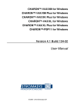
Figure 2–7 H3604 Console Module (Back)
Battery Backup Unit
W2
W4
J6
J1
J1 = TOY Clock Battery
J5 = H3604 Power
J6 = CPU Interface
W2 = Remote Boot Enable
W4 = FEPROM Write Enable
F2
F4
F1
J5
F3
F1 = ThinWire Ethernet Power, 0.5 A
PN = 12-09159-00
F2 = -12V Power, 0.062 A
PN = 90-09122-00
F3 = DSSI Terminator Power, 2.0 A
PN = 12-10929-06
F4 = Standard Ethernet Power, 1.5 A
PN = 12-10929-08
MLO-006351
CPU System Overview 2–13
CPU System Overview
2.4 BA440 Enclosure Components
The back of the console module has the components listed in Table 2–4.
Table 2–4 H3604 Console Module (Back)
Component
Function
Battery Backup Unit
Provides battery backup power to the SSC
RAM.
TOY Clock Battery connector (J1)
Provides the connection between the
battery backup unit and the SSC RAM.
H3604 power connector (J5)
Four-pin power connector to power harness
module.
CPU Interface connector (J6)
100-pin connector to the CPU module.
ThinWire Ethernet Power Fuse (F1)
Protects ThinWire Ethernet.
-12 V Power Fuse (F2)
Protects console serial line.
DSSI Terminator Power Fuse (F3)
Protects against shorts from the accidental
grounding of the DSSI cable power pin.
Standard Ethernet Power Fuse (F4)
Protects Standard Ethernet.
Remote Boot Enable jumper (W2)
Not used
FEPROM Write Enable jumper (W4)
This jumper must be in the write enable
position to update FEPROMs on the CPU
module. Refer to Chapter 6 for procedures
on updating ROMs.
-9 V DC/DC converter
Generates voltage for the Ethernet
transceiver.
(continued on next page)
2–14 CPU System Overview
CPU System Overview
2.4 BA440 Enclosure Components
Table 2–4 (Cont.) H3604 Console Module (Back)
Component
Function
Ethernet serial transceiver chip
Serial Interface Adapter (SIA)
Performs Ethernet serial transactions.
TOY clock oscillator
Time of year oscillator. Privides TOY signal
for the TOY clock in the system support
chip (SSC) on the CPU module.
CPU System Overview 2–15
CPU System Overview
2.4 BA440 Enclosure Components
2.4.2 System Control Panel (SCP)
The system control panel (SCP) (Figure 2–8) provides the controls to halt the
processor (external halt type) and enter console mode, as well as to restart the
system and return the processor state to power-up and self tests.
Figure 2–8 System Control Panel
Over Temperature
Warning Indicator
DC OK Indicator
Halt Button
Restart Button
MLO-008652
2–16 CPU System Overview
CPU System Overview
2.4 BA440 Enclosure Components
The SCP has the controls and indicators listed in Table 2–5.
Table 2–5 System Control Panel Controls and Indicators
Control/Indicator
Function
Over Temperature Warning
indicator
The red Over Temperature Warning indicator
flashes to indicate that the system’s internal
temperature is approaching a level that may cause
system components to overheat. In addition to the
flashing Over Temperature Warning indicator, an
audible alarm also provides warning of a possible
over temperature condition. If the components
continue to heat, the system will automatically shut
down to prevent components from being damaged.
DC OK indicator
The green DC OK indicator shows that the power
supply voltages are within the correct operating
range.
Halt Button
The Halt button is a two-position button. When you
press the button, the system halts. A red indicator
on the Halt button lights when the button is set
to the in position. Before you can enter console
commands, press the Halt button again to return
it to the out position. When the Halt button is
returned to the out position, the console mode
prompt >>> is displayed on the console terminal
screen. Now you can enter console commands. If
you inadvertently press the Halt button, type ‘‘c
Return ’’ to continue.
Caution
Pressing the Halt button halts
the system regardless of the
setting of the Break Enable
/Disable switch on the console
module.
(continued on next page)
CPU System Overview 2–17
CPU System Overview
2.4 BA440 Enclosure Components
Table 2–5 (Cont.) System Control Panel Controls and Indicators
Control/Indicator
Function
Restart Button
The Restart button has a green indicator. When
you press the Restart button, the system returns to
a power-up condition and self-tests are run. If you
have specified a device as the boot device and if the
Break/Enable Disable switch is set to disable, the
system will reboot system software.
2–18 CPU System Overview
CPU System Overview
2.4 BA440 Enclosure Components
2.4.3 BA440 Backplane
KA681/KA691/KA692/KA694-based systems use the BA440 (54–19354–01)
backplane, shown in Figure 2–9.
Figure 2–9 BA440 Backplane
Vterm Module
SCP
Connector
Mass Storage
Connectors
Power Supply
Connectors
Module
Connectors
12 11 10 9 8 7 6
Q-bus
Option
5
CPU
4 3 2 1
Fan Connector
Memory
Power
Board
for H3604
MLO-007695
CPU System Overview 2–19
CPU System Overview
2.4 BA440 Enclosure Components
2.4.4 Power Supply
The BA440 enclosure uses the H7874 power supply (Figure 2–10). Table 2–6
describes the power supply components.
Figure 2–10 H7874 Power Supply
Power Switch
AC Present Indicator
DC OK Indicator
Fan Failure
Indicator
Over Temperature
Condition Indicator
Power Bus
Connectors
Power Cable
Connector
MLO-004040
2–20 CPU System Overview
CPU System Overview
2.4 BA440 Enclosure Components
Table 2–6 H7874 Power Supply Switches, Controls, and Indicators
Control/Indicator
Function
AC Present indicator (orange)
Lights when the Power switch is set to on (1), and
the ac voltage is present at the input of the power
supply.
Power switch
The Power switch is used to turn system power on
and off. The off position is indicated by a 0; the on
position is indicated by a 1.
The Power switch also functions as the system
circuit breaker. In the event of a power surge, the
breaker will trip causing the power switch to return
to the off position (0). Turning on the system resets
the circuit breaker. If the circuit breaker trips, wait
one minute before turning the system back on.
DC OK indicator (green)
When the DC OK indicator is lit, the voltages are
within the correct operating range. An unlit DC OK
indicator shows a problem with the power supply.
Fan Failure indicator (amber)
The Fan Failure indicator lights if either of the
two cooling fans stops working. The power supply
will automatically shut down the system as a
precautionary measure when a fan failure is
detected.
Over Temperature indicator
(amber)
The Over Temperature indicator lights if the
system has shut down due to an over temperature
condition.
(continued on next page)
CPU System Overview 2–21
CPU System Overview
2.4 BA440 Enclosure Components
Table 2–6 (Cont.) H7874 Power Supply Switches, Controls, and Indicators
Control/Indicator
Function
Power bus connectors
Three power bus connectors allow you to configure
a power bus for systems expanded with a system
expander. The power bus allows you to turn power
on and off for the system through one power supply
designated as the main power supply: this way, one
power switch can control power for an expanded
system.
Note
DSSI VAXcluster systems
should not be configured with
a power bus. Inadvertently
shutting off a host system
and bringing down the cluster
defeats the added reliability of
a DSSI VAXcluster.
MO
The main out connector sends the power control
bus signal to the expander. One end of a power bus
cable is connected here; the other end is connected
to the SI (secondary in) connector of the expander
power supply.
SI
The secondary in connector receives the power bus
control signal from the main power supply. In a
power bus with more than one expander, the power
bus signal is passed along using the secondary in
and out connectors.
SO
The secondary out connector sends the signal down
the power bus for configurations of more than one
expander.
2–22 CPU System Overview
CPU System Overview
2.4 BA440 Enclosure Components
2.4.5 System Airflow
Two fans are located under the card cage (Figure 2–11). The power supply
monitors the fans. If either fan stops working, the Fan Failure indicator
on the power supply lights, and the system automatically shuts down as a
precautionary measure.
Figure 2–11 Fans
Captive Screws
MLO-004220
Some system managers request that the fans run at the maximum rate
at all times to take advantage of a potential increase in system reliability.
The system environment must not exceed the limits described in the Site
Preparation manual. Figure 2–12 shows the location of the fan speed control
(FSC) jumper on the bottom of the power supply. Setting the FSC jumper to
disable causes the fans to run at the maximum rate.
CPU System Overview 2–23
CPU System Overview
2.4 BA440 Enclosure Components
Figure 2–12 Fan Speed Control (FSC) Jumper Location
FSC
Enabled
(Factory
Setting)
FSC
Disabled
MLO-004204
2–24 CPU System Overview
3
System Setup and Configuration
This chapter describes the guidelines for the configuration of a KA681/KA691
/KA692/KA694-based system. Configuration issues covered in this chapter
include module order, mass storage configurations, system expansion, DSSI
VAXcluster configurations, and firmware commands and utilities used in
system configuration.
3.1 CPU and Memory Module Order
The five right-most BA440 backplane slots are dedicated to CPU and memory
modules. The number and type of option modules installed in slots 6 through
12 depend on your configuration. If you only have two DSSI ports, then slots
6 through 12 are available for Q–bus option modules. If your system has
four CPU DSSI ports, then slots 6 through 10 are available for Q–bus option
modules and slots 11 and 12 are DSSI bus bulkheads. See Table 3–1.
Table 3–1 BA440 Module Order
Slot
Module
1 through 4
Reserved for up to four MS690 memory modules. MS690
modules are installed from left to right with no gaps: first
memory module in slot 4, second memory module in slot 3,
and so on.
Note
Proper placement of memory modules
is necessary for FRU isolation using
error logs.
(continued on next page)
System Setup and Configuration 3–1
System Setup and Configuration
3.1 CPU and Memory Module Order
Table 3–1 (Cont.) BA440 Module Order
Slot
Module
5
CPU module: KA681 (L4005–BA), KA691 (L4005-AA),
KA692 (L4006-AA), KA694 (L4006–BA)
6 through 12
Q–bus options
OR
6 through 10
Q–bus options
11 and 12
DSSI ports
OR
6 through 9
Q–bus options
10 and 11
DSSI ports when M9404 is installed in slot 12
A system can have up to four memory modules. Memory modules are available
in 32 MB (MS690–BA), 64 MB (MS690–CA), and 128 MB (MS690–DA), and
can be used in any combination. The firmware logically configures the memory
modules at power-up.
Note
The MS690–BA may not be used with the KA692 or KA694 CPU
modules.
3.1.1 Installing Add-On MS690 Memory Modules
Perform the following steps to install add-on MS690 memory module(s). You do
not set any jumpers or switches on the memory module. The memory address
for the memory module is mapped by the system.
Caution
Turn off the system before installing modules. Installing modules while
this system is powered up can damage the modules.
1. Two captive screws hold the console module (H3604) in place. To loosen,
both screws should be turned counterclockwise. The console module is
hinged on the left. Swing the assembly open.
3–2 System Setup and Configuration
System Setup and Configuration
3.1 CPU and Memory Module Order
Note
Two cables connect to the H3604 console module: a ribbon cable which
connects to the CPU module; and a four-pin power harness connects to
a power harness module (also known as the power board H3604) which
plugs into the backplane. The power harness module is located directly
to the right of the CPU module.
2. Install the module(s) starting with the first empty slot, which is located on
the right side of the power harness module. The power harness module is
located between the CPU module (slot 5) and the first memory module (slot
4).
The memory module(s) must be installed in adjacent slots with no empty
slots between. Slots 12 through 6 are Q–bus slots, or slots 10 through 6 are
Q–bus slots and slots 12 and 11 are optional DSSI slots; slot 5 is the CPU
slot; and slots 4 through 1 are the memory module slots.
3. Make sure the ratchet handles on the memory module are on the right side
of the module.
Wearing the antistatic wrist strap, install the memory module in the first
available memory slot to the right of the CPU. Ensure that the memory
module is vertically aligned. Push the memory module in until the ratchet
handles engage with the enclosure frame. Push the ratchet handles inward
toward the rear of the cabinet until the memory module is firmly seated
in the backplane. When the memory module is firmly seated, the ratchet
handles will lock the module in place.
Note
The CPU and MS690 memory modules are equipped with ratchet
handles (Figure 3–1) which are shipped in a horizontal position. The
ratchet handles are designed to ensure that the modules are properly
seated in the backplane connectors.
4. Close the H3604 console module and lock the 1/4-turn captive screws.
5. To identify the memory module, place the MS690 option label (supplied
in the option kit) in the proper location on the H3604 panel. Indicate the
revision number and memory option (BA, CA, or DA).
System Setup and Configuration 3–3
System Setup and Configuration
3.1 CPU and Memory Module Order
Figure 3–1 Memory Module Ratchet Handles
Ejector
Handles
MLO-008453
6. Refer to Chapter 4 for information on initialization and acceptance testing.
3.2 General Module Order for Q–Bus Options
The order of the supported Q–bus options in the backplane depends on four
factors:
•
Relative use of devices in the system
•
Expected performance of each device relative to other devices
•
The ability of a device to tolerate delays between bus requests and bus
grants (called delay tolerance or interrupt latency)
•
The tendency of a device to prevent other devices farther from the CPU
from accessing the bus
3–4 System Setup and Configuration
System Setup and Configuration
3.2 General Module Order for Q–Bus Options
The supported options arranged by type are:
Communications
CXA16–AA/AF: 16-line DEC–423 asynchronous controller
CXB16–AA/AF: 16-line RS–422 asynchronous controller
CXY08–AA/AF: 8-line RS–232C asynchronous controller with modem
DEFQA–SA/SF: Q–bus FDDI adapter
DEFQA–DA/DF: Q–bus FDDI adapter
DEQRA–CA: Token Ring Network Controller
DESQA–SA/SF: ThinWire Ethernet adapter
DFA01–AA/AF: 2400/1200 BPS modem
DIV32–SA/SF: Q–bus ISDN basic rate access interface
DPV11–SA/SF: Q–bus synchronous programmable interface
DRV1W–SA/SF: General purpose 16-bit parallel DMA interface
DRV1J–SA/SF: Q–bus parallel interface
DSV11–SA/SF: Q–bus 2-line synchronous
KMV1A–SA/SF: Single-line programmable controller with DMA
General
ADQ32–SA/SF: 32-channel ADC module
ADV11–SA/SF: 16-channel ADC module
AXV11–SA/SF: 16-channel ADC, 2-channel DAC module
DRQ3B–SA/SF: Q–bus parallel I/O interface
DTC05–SA: Digital encoded voice, multifunction
IBQ01–SA/SF: DECscan/BITBUS controller
IEQ11–SA/SF: Dual-bit DMA serial Q–bus controller
KITHA–AA: Mira AS option
KWV11–SA/SF: Programmable real-time clock
LPV11–SA/SF: Line printer controller
MRV11: Q–bus, universal socket, 32-Kbyte EPROM
VS30U–GA/G3/G4: Graphics option
Mass Storage, Tape, Pedestal Expansions
EF51R–AA/AF: 107-Mbyte solid state storage element with data retention
EF52R–AA/AF: 205-Mbyte solid state storage element with data retention
EF53–AA/AF: 267-Mbyte solid state storage element without data retention
HSD05–JA/JF: DSSI to SCSI converter
RF35E–AA: 852-Mbyte half-height DSSI integrated storage element
RF352–AA/AF: Two RF35s for installation in one 5.25-inch storage cavity
RF36E–AA/AF: 1.6-Gbyte half-height DSSI integrated storage element
RF362–AA/AF: Two RF36s for installation in one 5.25-inch storage cavity
RF73E–AA/AF: 2.0-Gbyte full-height DSSI integrated storage element
RF72E–AA/AF: 1.0-Gbyte full-height DSSI integrated storage element
System Setup and Configuration 3–5
System Setup and Configuration
3.2 General Module Order for Q–Bus Options
RF71E–AA/AF: 400-Mbyte full-height DSSI integrated storage element
RF31E–AA/AF: 381-Mbyte half-height DSSI integrated storage element
RF31T–AA/AF: 381-Mbyte full-height DSSI integrated storage element
RF74E–AA/AF: 3.75-Gbyte full-height DSSI integrated storage element
TF85E–JA/JF: 2.6-Gbyte DSSI integrated storage element with 5.25-inch
cartridge
TF85–TA: 3.75-Gbyte DSSI tape drive in table top enclosure
TF86E–JA/JF: 6.0-Gbyte DSSI tape driver ISE for BA400-series 5.25-inch
storage cavity
TLZ04–JA/JF/GA: 1.2-Gbyte cassette (DAT) tape drive (requires KZQSA
storage adapter)
TLZ06–GA: 2.0-/4.0-Gbyte tabletop 4mm DAT drive (requires KEQSA SCSI
adapter)
TK70E–AA/AF/TQK70–SA/SF: 5.25-inch cartridge, 296-Mbyte tape drive,
tape controller
TK50E–AA/AF/TQK50–SA/SF: 5.25-inch cartridge, 95-Mbyte tape drive,
tape controller
KLESI–SA: Q–bus to LESI adapter
KFQSA–SE/SG: DSSI Q–bus adapter
KZQSA–SA/SF: Storage adapter for TLZ04 tape drive and RRD42 compact
disc drive
RA81/82: Storage array (separate cabinets only)
RA90/92: Storage array (separate cabinets only)
KDA50–SE/SG: SDI Q–bus adapter
KRQ50–SA/SF: Q–bus controller for RRD40–DC
TU81E–SA/SB: Magnetic tape (requires KLESI controller)
TSV05–SE/SF/SH/SJ: Q–bus TS05 magnetic tape controller
B400X: Expansion box with 10 Q–bus slots and up to 4 ISEs
R400X–B9: Expansion box with up to 7 RF-series ISEs
RRD40: 600-Mbyte CDROM tabletop drive (requires KRQ50 controller)
RRD42: 600-Mbyte tabletop compact disc drive (requires KZQSA storage
adapter)
RSV20–A: WORM optical drive subsystem (requires KLESI controller)
RWZ01: 594-Mbyte Magneto-Optical Disc (requires KZQSA storage
adapter)
ESE20: Electronic storage element (requires KDA50 controller)
3–6 System Setup and Configuration
System Setup and Configuration
3.3 Recommended Module Order of Q-Bus Options
3.3 Recommended Module Order of Q-Bus Options
The recommended module order for placement of Q–bus options is provided in
the following list:
MRV11 (Placement not critical)
AAV11
ADV11
AXV11
KWV11
DRV1J
KMV1A
DEQRA
DESQA
DEFQA
DPV11
DIV32
VS3OU
DFA01
CXA16
CXY08
CXB16
LPV11
DRV1W
KRQ50
IEQ11
ADQ32
DRQ3B
DSV11
KLESI
IBQ01
TSV05 (M7530 controller)
KDA50–SE
KFQSA–SE
KZQSA
TQK50
TQK70
M9060–YA
System Setup and Configuration 3–7
System Setup and Configuration
3.4 (Optional) DSSI Ports Assignment
3.4 (Optional) DSSI Ports Assignment
The last two slots in the BA440 enclosure will contain DSSI bulkheads if
ordered. Slot 11 is assigned Bus 2 and slot 12 is Bus 3.
3.5 Mass Storage Options (Internal)
The mass storage shelf of a BA440 enclosure provides four storage cavities
for embedded mass storage options. The rightmost storage cavity can contain
a tape drive (TF85/TF86, TK-series, or TLZ04); all four storage cavities can
contain an EF/RF-series ISE.
Combinations of dual-disk, single-disk, or tape ISEs can be used to gain the
full complement of seven DSSI devices on the internal DSSI bus (Bus 0).
VAX 4000 Model 500A/505A/600A/700A/705A systems can support the following
combinations of mass storage options embedded in the system enclosure:
•
One tape drive (TF85/TF86, TK-series, or TLZ04) and up to six EF
/RF-series ISEs using the dual-disk RF35.
•
No tape drive and up to seven RF-series ISEs using the dual-disk RF35.
Note
The RF35, which has dual-disk capability, can be ordered with a single
disk.
Figure 3–2 shows an example of a mass storage configuration consisting of a
TF85/TF86 tape drive, two RF35s, and two RF73s.
Rules for Numbering Storage Devices
Use the rules below for numbering (bus node ID and MSCP unit numbers)
storage devices:
•
For each DSSI bus, do not duplicate bus node ID numbers for your storage
devices/adapter. For Bus 0, you can have only one storage device identified
as bus node 0, one storage device as 1, and so on; for Bus 1, you can have
only one storage device identified as bus node 0, one storage device as 1,
and so on.
•
The previous rule also applies to DSSI VAXcluster configurations; all DSSI
bus node numbers for storage devices and DSSI adapters must be unique
in a shared DSSI bus.
3–8 System Setup and Configuration
System Setup and Configuration
3.5 Mass Storage Options (Internal)
Figure 3–2 Storage Configuration Example
ISE 3
ISE 2
ISE 1 and 0
Tape Drive
MLO-007696
•
By convention, the EF/RF-series ISEs are numbered in increasing order
from right to left beginning with zero.
•
DSSI adapters use the highest available bus nodes. The next highest
available bus node (usually five) is reserved for the TF-series tape drive.
•
When more than one DSSI bus is being used and the system is using
a nonzero allocation class, you need to assign new MSCP unit numbers
for devices on all but one of the DSSI buses since the unit numbers for
all DSSI devices connected to a system’s associated DSSI buses must be
unique. Refer to Section 3.8.3 for more information on setting parameters
for DSSI devices.
Note
If you change the bus node ID plugs, power down the system, change
the plugs and then power up the system.
System Setup and Configuration 3–9
System Setup and Configuration
3.6 System Expansion
3.6 System Expansion
The mass storage and Q–bus capacity of VAX 4000 Model 500A/505A/600A
/700A/705A systems can be increased using the following expanders.
3.6.1 Mass Storage Expanders
•
The R400X mass storage expander provides space for up to seven additional
EF/RF-series ISEs or up to six EF/RF-series ISEs and a tape drive (TF85
/TF86 or TLZ04). Using R400X expanders, you can fill both DSSI buses for
a total of 14 DSSI mass storage devices.
Note
Using the dual-disk RF35, the R400X can accommodate up to 13 ISEs.
3–10 System Setup and Configuration
System Setup and Configuration
3.6 System Expansion
•
The R215F expander provides space for up to three EF/RF-series ISEs.
This does not include the RF74.
Note
Using the dual-disk RF35, you can increase the number of ISEs—up to
seven ISEs per DSSI bus.
•
The SF100 storage array pedestal provides space for a TF857 magazine
tape subsystem and one SFxx storage array building block.
•
The SF200 storage array subsystem provides space for up to two TF857
magazine tape subsystems and up to six SFxx storage array building
blocks.
•
The SF12 is a desktop DSSI expander providing four 3.5-inch storage slots.
3.6.2 Q–Bus Expanders
•
The B400X expander provides 10 additional usable Q–bus slots for a
system total of 17 usable Q–bus slots. The B400X also has space for up
to four additional EF/RF-series ISEs or up to three ISEs and a tape drive
(TF85/TF86, TK70, or TLZ04).
Note
Using the dual-disk RF35, the B400X can accommodate up to seven
ISEs.
•
The B213F expander also provides 10 additional usable Q–bus slots and
provides space for up to three EF/RF-series ISEs or up to three ISEs and a
TK-series tape drive.
Note
Installing a B213F or R215F on a VAX 4000 system requires the
H4010–AA expander cable kit.
System Setup and Configuration 3–11
System Setup and Configuration
3.6 System Expansion
3.6.3 Control Power Bus for Expanders
The three power bus connectors on the H7874 power supply allow you to
configure a power bus for systems expanded with R400X and B400X expanders.
The power bus allows you to turn power on and off for one or more expanders
through the power supply designated as the main power supply (Figure 3–3).
Note
DSSI VAXcluster systems should not be configured with a power bus.
Inadvertently bringing down the cluster defeats the added reliability of
a DSSI VAXcluster.
Figure 3–3 Sample Power Bus Configuration
System
Expander 1
Expander 2
MLO-004041
3–12 System Setup and Configuration
System Setup and Configuration
3.6 System Expansion
3.6.4 Adding Options to the System Enclosure
To determine what options you can add to the system enclosure, you must
list the options currently installed and their power requirements on the VAX
4000 Model 500A/505A/600A/700A/705A Configuration Worksheet, provided in
Figure 3–4.
The worksheet in Figure 3–4 is for the BA440 enclosure. All backplane slots
and mass storage devices are powered by the H7874 power supply.
Use the worksheets as follows:
1. In the Module column, list all options and mass storage devices currently
installed in your system. The CPU module has already been entered.
Use the label on the cover panel of each slot to identify the module installed
in that slot.
2. List each embedded storage device.
3. List the options and mass storage devices you wish to add to your system.
4. If the system includes a TK50 or TK70 tape drive, list the TQK70 controller
last.
5. Fill in the power requirements for each module and each mass storage
device. The power requirements for the more common options are listed in
Table 3–2.
6. Add each column and make sure the totals do not exceed the specified
limit.
System Setup and Configuration 3–13
System Setup and Configuration
3.6 System Expansion
Figure 3–4 VAX 4000 Model 500A/505A/600A/700A/705A Configuration
Worksheet
Slot
Module
Current (Amps) 1
+5 Vdc +12 Vdc +3.3 Vdc -12 Vdc
Power
(Watts)
Bus Load
AC
DC
MEM 1
MEM 2
MEM 3
MEM 4
CPU
2
L4002-nA 3
4.8
1.6
53.8
4.0
1.0
CPU
2
L4005-nA 4
9.084
1.6
64.62
4.0
1.0
CPU
2
L4006-nA 5
8.6
1.6
62.2
4.0
1.0
584.0 W
31
20
3.2
0.0
Q-bus 1
Q-bus 2
Q-bus 3
Q-bus 4
Q-bus 5
Q-bus 6
Q-bus 7
Mass Storage:
Tape
1
2
3
4
Total these columns:
Must not exceed:
60.0 A
22.0 A
15.0 A
3.0 A
1. Total output power from +3.3 Vdc and +5 Vdc must not exceed 330 watts.
2. Power requirements in this line include CPU module, H3604 console module,
and backplane terminator combined.
3. KA690(L4002-AA), KA680(L4002-BA), or KA675(L4002-CA)
4. KA681 (L4005-BA) or KA691 (L4005-AA)
5. KA692 (L4006-AA)
6. KA694 (L4006-BA)
3–14 System Setup and Configuration
MLO-005361
System Setup and Configuration
3.6 System Expansion
Table 3–2 Power Requirements
Current
(Amps)
Max
Power
Max
Bus Loads
Option
Module
+5 V
+12 V
Watts
AC
DC
AAV11–SA
A1009–PA
2.10
0.00
10.50
2.5
0.5
ADQ32–SA
A030
4.45
0.00
22.25
2.5
0.5
ADV11–SA
A1008–PA
2.00
0.00
10.00
2.3
0.5
AXV11–SA
A026–PA
2.00
0.00
10.00
1.2
0.3
CXA16–AA
M3118–YA
1.60
0.20
10.40
3.0
0.5
CXB16–AA
M3118–YB
2.00
0.00
10.00
3.3
0.5
CXY08–AA
M3119–YA
1.64
0.395
12.94
3.0
0.5
DEFQA–DA
M7534–AD
5.60
0.1
31.0
4.9
1.5
DESQA–SA
M3127–PA
2.40
0.22
14.64
3.3
0.5
DEQRA–CA
M7533–AB
4.0
1.0
21.20
2.2
0.5
DFA01–AA
M3121–PA
1.97
0.04
10.30
3.0
1.0
DIV32–SA
M7571–PA
5.5
0.00
35.4
3.5
1.0
DPV11–SA
M8020–PA
1.20
0.30
9.60
1.0
1.0
DRQ3B–SA
M7658–PA
4.50
0.00
22.50
2.0
0.5
DRV1J–SA
M8049–PA
1.80
0.00
9.00
2.0
1.0
DRV1W–SA
M7651–PA
1.80
0.00
9.00
2.0
1.0
DSV11–SA
M3108
5.43
0.69
35.43
3.9
1.0
DTC05–SA
M3136
4.0
0.0
15.80
3.6
0.75
EF51R
–
0.0
2.3
27.6
N/A
N/A
EF52R
–
0.0
2.2
26.2
N/A
N/A
EF53
–
3.7
0.1
18.4
N/A
N/A
H36041
–
1.70
0.50
14.50
–
–
IBQ01–SA
M3125–PA
5.00
0.30
28.60
4.6
1.0
IEQ11–SA
M8634–PA
3.50
0.00
17.50
2.0
1.0
KDA50–SE
M7164
6.93
0.00
34.65
3.0
0.5
—–
M7165
6.57
0.03
33.21
–
–
1 Also
include –12 Vdc @ 0.25 A, 3 W.
(continued on next page)
System Setup and Configuration 3–15
System Setup and Configuration
3.6 System Expansion
Table 3–2 (Cont.) Power Requirements
Current
(Amps)
Max
Power
Max
Bus Loads
Option
Module
+5 V
+12 V
Watts
AC
DC
KFQSA–SA
M7769
5.50
0.00
27.50
4.4
0.5
KLESI–SA
M7740–PA
4.00
0.00
20.00
0.5
1.0
KRQ50–SA
M7552
2.70
0.00
13.50
2.7
1.0
KWV11–SA
M4002–PA
2.20
0.013
11.156
1.0
0.3
KXJ11–SF
M7616
6.0
0.4
46.8
2.0
1.0
KZQSA–SA
M5976
5.4
0.0
27.0
4.4
0.5
LPV11–SA
M8086–PA
2.80
0.00
14.00
1.8
0.5
M9404–PA
M9404
–
0.00
0.0
–
–
M9405–PA
M9405
–
0.00
0.0
–
–
MRV11–D
M8578
1.602
0.00
8.00
3.0
0.5
MS690–BA
L4004–BA
5.03
0.00
26.5
–
–
MS690–CA
L4004–CA
4.2
0.00
21.0
–
–
MS690–DA
L4004–DA
6.4
0.00
32.0
–
–
RF312–xx
–
0.86(x2)
2.89(x2)
33.2
N/A
N/A
RF31E–AA/AF
–
1.2
2.21
32.52
N/A
N/A
RF31F–AA/AF
–
1.2
2.21
32.52
N/A
N/A
RF31T–AA/AF
–
1.71
0.85
13.7
N/A
N/A
RF352–AA/AF
–
1.69
5.10
33.0
N/A
N/A
RF35E–AA/AF
–
0.71
2.29
31.1
N/A
N/A
RF362–AA
–
0.86(x2)
2.89(x2)
16.6(x2)
N/A
N/A
RF36E–AA
–
0.86
2.89
16.6
N/A
N/A
RF71E–AA/AF
–
1.25
1.64
25.93
N/A
N/A
RF72E–AA/AF
–
1.20
1.75
27.00
N/A
N/A
RF73E–AA/AF
–
1.20
1.75
27.00
N/A
N/A
RF74E–AA
–
1.0
2.5
35.0
N/A
N/A
TF85E–JA/JF
–
1.50
2.40
36.30
N/A
N/A
2 Value
is for the unpopulated module only.
(continued on next page)
3–16 System Setup and Configuration
System Setup and Configuration
3.6 System Expansion
Table 3–2 (Cont.) Power Requirements
Current
Option
Module
(Amps)
Max
Power
Max
+5 V
+12 V
Watts
AC
DC
Bus Loads
TK50E–AA
–
1.50
2.40
36.30
N/A
N/A
TK70E–AA/AF
–
1.50
2.40
36.30
N/A
N/A
TLZ04–JA/JF
–
1.5
2.4
36.3
N/A
N/A
TLZ06–GA/GF
–
1.2
1.75
12.0
N/A
N/A
TQK50–SA/SF
M7546
2.9
0.00
14.5
2.8
0.5
TQK70–SA/SF
M7559
3.50
0.00
17.50
4.3
0.5
TSV05–SA
M7530
6.50
0.00
32.50
1.5
1.0
VCB02–A
M7615
4.60
0.10
24.2
3.5
1.0
VCB02–B
M7168
M7169
8.85
0.47
49.89
3.5
1.0
VCB02–C
(2) M7168
M7169
12.0
0.47
65.64
3.5
1.0
3.7 DSSI VAXclusters
A DSSI VAXcluster configuration is one in which up to three systems can
access the same DSSI devices. Some failures of any system can be tolerated,
in which case the remaining system(s) continues to access all available DSSI
devices and assure continued processing. See Figure 3–5.
If one of the CPU modules fails, all satellite nodes booted through that CPU
module lose connections to the system disk. However, the DSSI VAXcluster
enables each satellite node to know that the system disk is still available
through a different path—that of the functioning CPU module. A connection
through that CPU is then established, and the satellite nodes are able to
continue operation. The entire cluster will run slower, since one CPU is now
serving the satellite nodes of both systems. Processing can continue, however,
until Digital Services can repair the problem.
System Setup and Configuration 3–17
System Setup and Configuration
3.7 DSSI VAXclusters
Figure 3–5 DSSI Cabling for a Generic Two-System DSSI VAXcluster
Configuration
SYS0
RFxx
SYS1
RFxx
RFxx
RFxx
RFxx
RFxx
DSSI
Boot
Node #2
Boot
Node #1
Ethernet
Satellite
Node
Satellite
Node
Satellite
Node
LAT
LAT
MLO-003295
3–18 System Setup and Configuration
System Setup and Configuration
3.7 DSSI VAXclusters
A DSSI VAXcluster system cannot recover from the following conditions:
•
System disk failure, which can be caused by such factors as a power supply
failure in the enclosure containing the disk.
•
DSSI cabling failure, which must be repaired to continue operation.
3.7.1 DSSI VAXcluster Configuration Rules
•
An Ethernet (NI)/FDDI is required on all CPU nodes.
•
A DECnet license is required (at least one full function license).
•
At least one common (primary) DSSI bus is required to connect with a
system disk containing system critical files.
•
VAXcluster and OpenVMS license is required.
•
A maximum of eight nodes per DSSI bus:
a. Each adapter or ISE (disk/tape) counts as one node.
b. A DSSI bus is a collection of all DSSI cable/path segments (inside and
outside of cabinets) between two end terminators.
c.
Each node must have a unique bus node ID number (0–7).
•
A maximum of three CPUs/adapters per DSSI bus is supported.
•
The DSSI bus MUST be terminated at both ends.
•
The DSSI bus MUST have a common ground between all elements (CPU,
disks). The ground offset is a function of the total DSSI bus length
(terminator to terminator).
Use a voltmeter to make sure the ground offset voltage between any two
enclosures does not exceed one of the limits listed below.
Allowable Ground Offset Voltage
Total Bus Length
DC
AC (rms)
Up to 20 meters (65 feet)
(Office environment)
200 millivolts
70 millivolts
20 to 25 meters (65 to 82 feet)
(Computer room)
40 millivolts
14 millivolts
Total bus length includes all DSSI cable lengths, internal and external.
Refer to the DSSI VAXcluster Installation and Troubleshooting manual for
instructions on calculating internal cable lengths.
System Setup and Configuration 3–19
System Setup and Configuration
3.7 DSSI VAXclusters
To measure the ground offset voltage, connect the voltmeter leads to bare
(unpainted) metal on each enclosure.
Note
The ground offset voltage may vary over time if equipment is added
to the system or plugged into the power outlets. Therefore, this
measurement does not guarantee that the voltage will remain within
acceptable limits.
•
Maximum single cable length is 15 m (50 ft) between connectors.
•
Disconnecting the DSSI cables is NOT allowed while bus is operational.
•
Number of DSSI buses per CPU:
CPU
DSSI Buses
KA630
2 KFQSAs on Q–bus
KA640
1 Embedded DSSI Adapter (EDA), 2 KFQSA on Q–bus
KA650/KA655
2 KFQSAs on Q–bus
KA660
1 Embedded DSSI Adapter (EDA), 2 KFQSA on Q–bus
KA670
2 Embedded DSSI Adapters (EDAs), 2 KFQSA on Q–bus
KA675
2 Embedded DSSI Adapters (EDAs), 2 KFQSA on Q–bus
KA680
2 Embedded DSSI Adapters (EDAs), 2 KFQSA on Q–bus
KA690
2 Embedded DSSI Adapters (EDAs), 2 KFQSA on Q–bus
KA681
2 or 41 Embedded DSSI Adapters (EDAs), 2 KFQSA on Q–bus
KA691
2 or 41 Embedded DSSI Adapters (EDAs), 2 KFQSA on Q–bus
KA692
2 or 41 Embedded DSSI Adapters (EDAs), 2 KFQSA on Q–bus
KA694
2 or 41 Embedded DSSI Adapters (EDAs), 2 KFQSA on Q–bus
6xxx
6 KFMSAs per system
9000
6 KFMSAs per XMI
12 KFMSAs per system
1 2 embedded DSSI adapters on the CPU module plus 2 DSSI adapters on the optional DSSI
daughter card (KFDDB).
•
The minimum OpenVMS revision for DSSI VAXcluster of more than two
nodes with:
a. VAX 4000 Model 400 is OpenVMS 5.5–2
3–20 System Setup and Configuration
System Setup and Configuration
3.7 DSSI VAXclusters
b. VAX 4000 Model 500 is OpenVMS 5.5
c.
VAX 4000 Model 500A is OpenVMS 5.5–2H4
d. VAX 4000 Model 505A is OpenVMS 5.5–2H4
e.
VAX 4000 Model 600 is OpenVMS 5.5–2
f.
VAX 4000 Model 600A is OpenVMS 5.5–2H4
g. VAX 4000 Model 700A is OpenVMS 5.5–2H4
h. VAX 4000 Model 705A is OpenVMS 5.5–2H4
•
OpenVMS 6.0 does not support any VAX 4000 platforms.
•
These rules apply to Digital supplied hardware. Third party devices may
not conform to DSSI electrical specification requirements. Therefore,
bus length, ground offset, basic noise margining, and warm swap
characteristics are at risk when using third party devices.
•
Like adapters should be connected together whenever possible.
•
Like CPUs should be connected together whenever possible.
For more information on DSSI VAXcluster configurations, refer to the DSSI
VAXcluster Installation and Troubleshooting manual. Figure 3–6 and
Figure 3–7 show two popular DSSI VAXcluster configurations using a VAX
4000 system.
System Setup and Configuration 3–21
System Setup and Configuration
3.7 DSSI VAXclusters
Figure 3–6 Two-System DSSI VAXcluster
System A
Ststem B
3 2 1
0
2 1 0
5
6 6
7 7
DSSI Cables
Shared DSSI Buses and Devices
DSSI Terminator Locations
System A
DSSI
Adapter 1
DSSI
Adapter 0
SHAC
Bus Node 6
System B
KAnn
KAnn
SHAC
Bus Node 6
SHAC
Bus Node 7
2
1
0
5
0
1
2
3
DSSI
Adapter 0
DSSI
Adapter1
SHAC
Bus Node 7
DSSI Bus Nodes for Storage Devices in System B
DSSI Bus Nodes for Storage Devices in System A
MLO-008312
3–22 System Setup and Configuration
System Setup and Configuration
3.7 DSSI VAXclusters
Figure 3–7 Expanded Two-System DSSI VAXcluster
System A
Expander
2 1 0
3 2 1
0
6 5 4
System B
5 4 3
DSSI Terminator Locations
SHAC
Bus Node 6
0
1
2
3
4
SHAC
Bus Node 7
5
System A
DSSI
Adapter 1
System B
KAnn
KAnn
DSSI
Adapter 0
DSSI
Adapter 0
DSSI
Adapter1
SHAC
Bus Node 7
SHAC
Bus Node 6
0
1
System A
2
3
4
5
System B
DSSI Bus Nodes for Storage Devices in Expander
DSSI Bus Nodes for Storage Devices in System A and B
MLO-008663
System Setup and Configuration 3–23
System Setup and Configuration
3.8 Firmware Commands and Utilities Used in System Configuration
3.8 Firmware Commands and Utilities Used in System
Configuration
Several commands and utilities are needed to configure a system. This
section covers commands for examining and setting system parameters,
DSSI parameters, and module addresses. For a complete listing of firmware
commands, refer to Appendix A.
3.8.1 Examining System Configuration
Several variations of the SHOW command provide a display of options and key
configuration information.
•
SHOW DEVICE — Lists devices (mass storage, Ethernet, and Q–bus) in
the system. (The SHOW DEVICE command combines the information
displayed using the SHOW command with DSSI, UQSSP, SCSI, and
Ethernet.)
•
SHOW DSSI — Lists all DSSI devices and their associated DSSI
parameters for embedded DSSI adapters.
•
SHOW DSSI_ID — Lists the DSSI node ID for each adapter.
•
SHOW ETHERNET — Lists the hardware Ethernet address for each
Ethernet adapter.
•
SHOW QBUS — Lists all Q–bus devices and their I/O addresses in hex,
the address as it would appear in the Q–Bus I/O space in octal, as well as
the word data read in hex.
•
SHOW SAVED_STATE — Lists the non-volatile console parameter values
stored in FEPROM.
•
SHOW SCSI — Lists all SCSI devices in the system.
•
SHOW SCSI_ID — Lists the SCSI node ID for each adapter.
•
SHOW UQSSP — Lists all DSSI devices for KFQSA-based DSSI adapters.
•
SHOW MEMORY — Lists main memory configuration for each memory
board.
3–24 System Setup and Configuration
System Setup and Configuration
3.8 Firmware Commands and Utilities Used in System Configuration
Sample displays of some of the above commands are provided below.
>>>SHOW DEVICE
DSSI Bus 0 Node 0 (CLYDE)
-DIA0 (RF73)
DSSI Bus 0 Node 1 (BONNIE)
-DIA1 (RF73)
DSSI Bus 0 Node 5 (TFDR1)
-MIA5 (TF85/TF86)
DSSI Bus 0 Node 6 (*)
DSSI Bus 1 Node 7 (*)
UQSSP Disk Controller 0 (772150)
-DUA20 (RF31)
UQSSP Disk Controller 1 (760334)
-DUB21 (RF31)
UQSSP Disk Controller 2 (760340)
-DUC22 (RF31)
UQSSP Disk Controller 3 (760322)
-DUD23 (RF31)
UQSSP Tape Controller 0 (774500)
-MUA0 (TK70)
SCSI Adaptor 0 (761400), SCSI ID 7
-MKA0 (DEC TLZ04 1991(c)DEC)
Ethernet Adapter
-EZA0 (08-00-2B-06-10-42)
>>>SHOW DSSI
DSSI Bus 0 Node 0
-DIA0 (RF73)
DSSI Bus 0 Node 1
-DIA1 (RF73)
DSSI Bus 0 Node 5
-MIA5 (TF85/TF86)
DSSI Bus 0 Node 6
DSSI Bus 1 Node 7
>>>
(CLYDE)
(BONNIE)
(TFDR1)
(*)
(*)
>>>SHOW ETHERNET
Ethernet Adapter
-EZA0 (08-00-2B-0B-29-14)
>>>SHOW UQSSP
UQSSP Disk Controller
-DUA20 (RF31)
UQSSP Disk Controller
-DUB21 (RF31)
UQSSP Disk Controller
-DUC22 (RF31)
UQSSP Disk Controller
-DUD23 (RF31)
UQSSP Tape Controller
-MUA0 (TK70)
0 (772150)
1 (760334)
2 (760340)
3 (760322)
0 (774500)
System Setup and Configuration 3–25
System Setup and Configuration
3.8 Firmware Commands and Utilities Used in System Configuration
>>SHOW QBUS
Scan of Q-bus I/O Space
-20001920 (774440) = FF08 DELQA/DESQA
-20001922 (774442) = FF00
-20001924 (774444) = FF2B
-20001926 (774446) = FF08
-20001928 (774450) = FFD7
-2000192A (774452) = FF41
-2000192C (774454) = 0000
-2000192E (774456) = 1030
-20001F40 (777500) = 0020 IPCR
Scan of Q-bus Memory Space
>>>SHOW SCSI
SCSI Adapter 0 (761300), SCSI ID 7
-MKA500 (DEC TLZ04 1991 (c) DEC)
>>>SHOW MEMORY
Memory 0: 00000000 to 01FFFFFF, 32 Mbytes, 0 bad pages
Total of 32 Mbytes, 0 bad pages, 112 reserved pages
3.8.2 Using the CONFIGURE Command to Determine CSR Addresses
for Q–Bus Modules
Each Q–bus module in a system must use a unique device address and
interrupt vector. The device address is also known as the control and status
register (CSR) address. Most modules have switches or jumpers for setting
the CSR address values. The value of a floating address depends on what
other modules are housed in the system. The CONFIGURE command is
used to determine what the proper CSR addresses should be for the given
configuration. You can then configure the Q–bus modules according to this
information.
Note
These recommended values simplify the use of the MDM diagnostic
package and are compatible with OpenVMS device drivers. You can
select nonstandard addresses, but they require a special setup for
use with OpenVMS drivers and MDM. See the MicroVAX Diagnostic
Monitor User’s Guide for information about the CONNECT and
IGNORE commands, which are used to set up MDM for testing
nonstandard configurations.
3–26 System Setup and Configuration
System Setup and Configuration
3.8 Firmware Commands and Utilities Used in System Configuration
Determine CSR address values for a module as follows:
1. Use the SHOW QBUS firmware command to get a listing of the Q–bus
modules currently in the system.
2. Determine the correct values for the module using the CONFIGURE
firmware command. The CONFIG utility eliminates the need to boot the
OpenVMS operating system to determine CSRs and interrupt vectors.
Enter the CONFIGURE command, then HELP for the list of supported
devices. Enter the device and number of devices for all existing modules in
the system, as well as for those devices you are adding.
>>>CONFIGURE
Enter device configuration, HELP, or EXIT
Device, Number? help
Devices:
Devices:
LPV11
KXJ11
RLV12
TSV05
DMV11
DELQA
RRD50
RQC25
RV20
KFQSA-TAPE
CXA16
CXB16
LNV21
QPSS
KWV11C
ADV11D
DRQ3B
VSV21
IDV11D
IAV11A
DESNA
IGQ11
KWV32
KZQSA
Device,Number?
Numbers:
1 to 255, default is 1
Device,Number? cxa16,1
Device,Number? desqa,1
Device,Number? tqk70
Device,Number? qza
Device,Number? kfqsa-disk
Device,Number? exit
DLV11J
RXV21
DEQNA
KFQSA-DISK
KMV11
CXY08
DSV11
AAV11D
IBQ01
IAV11B
DIV32
M7577
DZQ11
DRV11W
DESQA
TQK50
IEQ11
VCB01
ADV11C
VCB02
IDV11A
MIRA
KIV32
LNV24
DZV11
DRV11B
RQDX3
TQK70
DHQ11
QVSS
AAV11C
QDSS
IDV11B
ADQ32
DTCN5
M7576
DFA01
DPV11
KDA50
TU81E
DHV11
LNV11
AXV11C
DRV11J
IDV11C
DTC04
DTC05
DEQRA
Address/Vector Assignments
-774440/120 DESQA
-772150/154 KFQSA-DISK
-774500/260 TQK70
-760440/300 CXA16
-761300/310 KZQSA
System Setup and Configuration 3–27
System Setup and Configuration
3.8 Firmware Commands and Utilities Used in System Configuration
Note
Of the devices listed in the CONFIG display, not all are supported
on the VAX 4000 Model 500A systems. See Section 3.2 for supported
options.
The LPV11–SA has two sets of CSR address and interrupt vectors. To
determine the correct values for an LPV11–SA, enter LPV11,2 at the
DEVICE prompt for one LPV11–SA or enter LPV11,4 for two LPV11–SA
modules.
3. See the Microsystems Options manual for switch and CSR and interrupt
vector jumper settings for supported options.
Note
The CSR address for KFQSA storage adapter is programmed using
firmware commands. Refer to the Appendix H for using the SET/HOST
/UQSSP/MAINT command to access the Diagnostic Utility Program
(DUP) driver utility to configure the CSRs for the KFQSA module.
3.8.3 Setting and Examining Parameters for DSSI Devices
Two types of DSSI storage adapters are available for VAX 4000 systems: an
embedded DSSI adapter, which is part of the CPU, and the KFQSA adapter.
The KA681/KA691/KA692/KA694 CPU has two embedded DSSI adapters: Bus
0 and Bus 1. The optional KFDDB DSSI daughter card provides two additional
embedded DSSI adapters, Bus 2 and Bus 3.
Each adapter provides a separate DSSI bus that can support up to eight nodes,
where the adapter and each DSSI storage devices count as one node, hence
each DSSI adapter can support up to seven DSSI storage devices (six DSSI
storage devices for a two-system DSSI VAXcluster; five DSSI storage devices
for a three-system DSSI VAXcluster configuration). The adapters make a
connection between the CPU and the requested device on their respective
DSSI bus. Each DSSI device has its own controller and server that contain the
intelligence and logic necessary to control data transfers over the DSSI bus.
3–28 System Setup and Configuration
System Setup and Configuration
3.8 Firmware Commands and Utilities Used in System Configuration
3.8.3.1 DSSI Device Parameters
Six principal parameters are associated with each DSSI device:
•
Bus Node ID
•
ALLCLASS
•
UNITNUM
•
FORCEUNI
•
NODENAME
•
SYSTEMID
Note
Each of these parameters, with the exception of the bus node ID, are
programmed and examined using the console-based Diagnostic and
Utility Program (DUP) driver utility. The bus node ID is determined by
either the bus node ID plug or by programming the ID number using
the SET DSSI_ID console command.
A brief description of each parameter follows:
The bus node ID parameter is provided by the bus node ID plug on the device’s
front panel or by overriding the plug by using the SET DSSI_ID command at
the console level. Each DSSI bus can support up to eight nodes, 0–7. Each
DSSI adapter and each device count as a node. Hence, in a single-system
configuration, a DSSI bus can support up to seven devices, bus nodes 0–6
(with node 7 reserved for the adapter); in a two-system DSSI VAXcluster
configuration, up to six devices, 0–5 (with nodes 6 and 7 reserved for the
adapters); in a three-system DSSI VAXcluster configuration, up to five devices,
0–4 (with nodes 5, 6, and 7 reserved for the adapters).
The ALLCLASS parameter determines the device allocation class. The
allocation class is a numeric value from 0 to 255 that is used by the OpenVMS
operating system to derive a path-independent name for multiple access paths
to the same device. The ALLCLASS firmware parameter corresponds to the
OpenVMS SYSGEN parameter ALLOCLASS.
DSSI devices are shipped from the factory with a default allocation class
of zero. Each device to be served to a cluster must have a nonzero
allocation class that matches the allocation class of the system. Refer
to the OpenVMS VAXcluster manual for rules on specifying allocation class
values.
System Setup and Configuration 3–29
System Setup and Configuration
3.8 Firmware Commands and Utilities Used in System Configuration
The UNITNUM parameter determines the unit number of the device. By
default, the device unit number is supplied by the bus node ID plug on the
device’s front panel. Systems with multiple DSSI buses, as described
later in this section, require that the default values be replaced
with unique unit numbers. To set unit numbers and override the default
values, you use the console-based DUP driver utility to supply values to
the UNITNUM parameter and to set a value of zero to device parameter
FORCEUNI.
The FORCEUNI parameter controls the use of UNITNUM to override
the default device unit number supplied by the bus node ID plug. When
FORCEUNI is set to a value of 0, the operating system uses the value assigned
to the UNITNUM parameter; when FORCEUNI is set to a value of 1, the
operating system uses the value supplied by the bus node ID plug.
The NODENAME parameter allows each device to have an alphanumeric node
name of up to eight characters. DSSI devices are shipped from the factory with
a unique identifier, such as R7CZZC, R7ALUC, and so on. You can provide
your own node name.
The SYSTEMID parameter provides a number that uniquely identifies the
device to the operating system. This parameter is modified when replacing a
device using warmswapping procedures.
3.8.3.2 How the OpenVMS Operating System Uses the DSSI Device Parameters
This section describes how the operating system uses the parameters to form
unique identifiers for each device. Configurations that require you to assign
new unit numbers for devices are also described.
With an allocation class of zero, the operating system can use the default
parameter values to provide each device with a unique device name. The
operating system uses the node name along with the device logical name in the
following manner:
NODENAME$DIAu
where:
NODENAME is a unique node name and u is the unit number.
With a nonzero allocation class, the operating system relies on unit number
values to create a unique device name. The operating system uses the
allocation class along with the device logical name in the following manner:
3–30 System Setup and Configuration
System Setup and Configuration
3.8 Firmware Commands and Utilities Used in System Configuration
$ALLCLASS$DIAu
where:
ALLCLASS is the allocation class for the system and devices, and u is a unique
unit number.
Using mass storage expanders, you can fill multiple DSSI buses: buses 0 and
1 supplied by the CPU module, and a third and fourth DSSI bus using two
KFQSA adapters. Each bus can have up to seven DSSI devices (bus nodes 0–
6). When more than one bus is being used, and your system is using a nonzero
allocation class, you need to assign new unit numbers for devices on all but
one of the DSSI buses, since the unit numbers for all DSSI storage devices
connected to a system’s associated DSSI buses must be unique.
Figure 3–8 illustrates the need to program unit numbers for a system using
more than one DSSI bus and a nonzero allocation class. In the case of the
nonzero allocation class, the operating system sees three of the ISEs as
having duplicate device names, which is an error, as all unit numbers must be
unique.
System Setup and Configuration 3–31
System Setup and Configuration
3.8 Firmware Commands and Utilities Used in System Configuration
Figure 3–8 OpenVMS Operating System Requires Unique Unit Numbers for
DSSI Devices
Allocation Class=0
Nonzero Allocation Class
(Example: ALLCLASS=1)
R7BUCC$DIA0
$1$DIA0
R7CZZC$DIA1
$1$DIA1
R7ALUC$DIA2
$1$DIA2
R7EB3C$DIA3
$1$DIA3
TFDR1$MIA5
$1$MIA5
R7IDFC$DIA0
$1$DIA0
R7IBZC$DIA1
$1$DIA1
R7IKJC$DIA2
$1$DIA2
R7ID3C$DIA3
$1$DIA3
R7XA4C$DIA4
$1$DIA4
R7QIYC$DIA5
$1$DIA5
R7DA4C$DIA6
$1$DIA6
* Duplicate 0
* Duplicate 1
* Duplicate 2
* Duplicate 3
* Nonzero allocation class examples with an asterisk indicate duplicate device names.
For one of the DSSI busses, the unit numbers need to be reprogrammed to avoid this error.
MLO-007176
3–32 System Setup and Configuration
System Setup and Configuration
3.8 Firmware Commands and Utilities Used in System Configuration
Note
Digital recommends configuring systems to have unique unit numbers
even for standalone systems using an allocation class of zero. This
practice will avoid problems with duplicate device names if the system
is later configured in a cluster.
The following instructions describe how to change DSSI parameters, using the
DUP driver utility. In the example procedures, the allocation class will be set
to 1, the devices for Bus 0 (in the VAX 4000) will be assigned new unit numbers
(to avoid the problem of duplicate unit numbers), and the system disk will be
assigned a new node name. To examine DSSI parameters from the OpenVMS
operating system, refer to Section 3.8.3.4.
Figure 3–9 shows sample DSSI buses and bus node IDs for an expanded VAX
4000 Model 500A system.
System Setup and Configuration 3–33
System Setup and Configuration
3.8 Firmware Commands and Utilities Used in System Configuration
Figure 3–9 Sample DSSI Buses for an Expanded VAX 4000 Model 500A
System
System
Expander
2 1 0
5
3 2 1
0
6 5 4
7 7
Bus 0
DSSI Cable
Bus 1
Dssi Terminator Locations
MLO-008628
1. Enter the console mode.
The procedure for programming parameters for DSSI devices from console
mode requires that you issue commands to those devices at the console
prompt (>>>). You may enter these commands in either uppercase or
lowercase letters. Unless otherwise instructed, enter each command, then
press Return.
Enter console mode as follows:
a. Set the Break Enable/Disable switch on the system console module to
the enable position (up, position 1).
b. Set the Power switch for each unit (each system in a DSSI VAXcluster
configuration, and any expanders for expanded systems) to on (1).
Wait for the system to display the console prompt (>>>).
2. To display the DSSI devices on embedded DSSI buses, enter SHOW DSSI
at the console prompt. To display the DSSI devices on KFQSA-based DSSI
buses, enter SHOW UQSSP.
3–34 System Setup and Configuration
System Setup and Configuration
3.8 Firmware Commands and Utilities Used in System Configuration
The firmware displays two lines of information for each device. For
embedded DSSI, the firmware displays the following:
•
The first line contains the bus number, node number, and node name.
•
The second line contains the device name and unit number followed by
the device type in parentheses.
For embedded DSSI, the device name consists of the letters DIAu or DIBu
(MIAu or MIBu for the TF85/TF86 tape drive)—devices on bus 0 are listed
as DIA, devices on bus 1 are listed as DIB—and u is a unique unit number.
The embedded DSSI adapter for each bus is identified by an asterisk (*).
The embedded DSSI display for Example 3–1 shows a system with four
DSSI devices (unit numbers 0–3) and an R400X expander with seven DSSI
devices (unit numbers 0–6).
Example 3–1 SHOW DSSI Display (Embedded DSSI)
>>>SHOW DSSI
DSSI Bus 0 Node 0
-DIA0 (RF31)
DSSI Bus 0 Node 1
-DIA1 (RF31)
DSSI Bus 0 Node 2
-DIA2 (RF31)
DSSI Bus 0 Node 5
-MIA5 (TF85/TF86)
DSSI Bus 0 Node 6
(R7ALUC)
(R7EB3C)
(R7EB22)
(TFDR1)
(*)
DSSI Bus 1 Node 0 (SNEEZY)
-DIB0 (RF31)
DSSI Bus 1 Node 1 (DOPEY)
-DIB1 (RF31)
DSSI Bus 1 Node 7 (*)
DSSI Bus 2 Node 0 (SLEEPY)
-DIC0 (RF31)
DSSI Bus 2 Node 1 (GRUMPY)
-DIC1 (RF31)
DSSI Bus 2 Node 7 (*)
DSSI Bus 3 Node 0 (BASHFUL)
-DID0 (RF31)
DSSI Bus 3 Node 1 (DOC)
-DID1 (RF31)
DSSI Bus 3 Node 7 (*)
>>>
System Setup and Configuration 3–35
System Setup and Configuration
3.8 Firmware Commands and Utilities Used in System Configuration
For KFQSA-based DSSI, the firmware displays the following:
•
The first line contains the UQSSP disk controller number and device node
name.
•
The second line contains the device name and unit number followed by the
device type in parentheses.
For KFQSA-based DSSI, the device name consists of the letters DUcu,
where c is the controller letter, and u is a unique unit number.
Example 3–2 shows a sample KFQSA-based DSSI bus.
Example 3–2 SHOW UQSSP Display (KFQSA-Based DSSI)
>>>SHOW UQSSP
UQSSP Disk Controller
-DUA0 (RF31)
UQSSP Disk Controller
-DUB1 (RF31)
UQSSP Disk Controller
-DUC2 (RF31)
UQSSP Disk Controller
-DUD3 (RF31)
UQSSP Tape Controller
-MUA0 (TK70)
0 (772150)
1 (760334)
2 (760340)
3 (760322)
0 (774500)
For the examples in this section, each device will be assigned an allocation
class of 1, and the system disk will be given a new node name. Also, devices
DIA0, DIA1, and DIA2; and DUA0, DUB1, DUC2, and DUD3 will be assigned
new unit numbers.
Note
The DUP server examples throughout this section are for RF-series
ISEs. The displays for the TF85/TF86 tape drive differ slightly from
the RF-series displays.
3.8.3.3 Entering the DUP Driver Utility from Console Mode
To examine and change DSSI parameters, you must first activate the DUP
driver utility by setting host to the specific device for which you want to modify
or examine parameters.
3–36 System Setup and Configuration
System Setup and Configuration
3.8 Firmware Commands and Utilities Used in System Configuration
Use the following command for embedded DSSI:
SET HOST/DUP/DSSI/BUS:<bus_number> <node_number> PARAMS
where:
<bus_number> is the DSSI bus number (0 or 1), and <node_number> is the
bus node ID (0–6) for the device on the bus.
Use the following command for KFQSA-based DSSI:
SET HOST/DUP/UQSSP/DISK <controller_number> PARAMS
where:
<controller_number> is the controller number (provided by the SHOW UQSSP
display) for the device on the bus.
In Example 3–3, SET HOST/DUP/DSSI/BUS:1 0 PARAMS is entered to start the
DUP server for the ISE at node 0 of embedded DSSI bus 1. In Example 3–4,
SET HOST/DUP/UQSSP/DISK 0 PARAMS is entered to start the DUP server for the
ISE at controller 0 of a KFQSA-based DSSI bus.
Example 3–3 Accessing the DUP Driver Utility from Console Mode
(Embedded DSSI)
>>>SET HOST/DUP/DSSI/BUS:1 0 PARAMS
Starting DUP server...
Copyright (c) 1991 Digital Equipment Corporation
PARAMS>
Example 3–4 Accessing the DUP Driver Utility from Console Mode (KFQSABased DSSI)
>>>SET HOST/DUP/UQSSP/DISK 0 PARAMS
Starting DUP server...
Copyright (c) 1991 Digital Equipment Corporation
PARAMS>
System Setup and Configuration 3–37
System Setup and Configuration
3.8 Firmware Commands and Utilities Used in System Configuration
3.8.3.4 Entering the DUP Driver Utility from the OpenVMS Operating System
To examine and change DSSI parameters, you must first access the DUP driver
utility by setting host to the specific device for which you want to modify or
examine parameters.
To access the DUP driver from the OpenVMS operating system:
a. Connect to the Diagnostic and Utility Program (DUP) and load its driver
using the OpenVMS System Generation Utility (SYSGEN) as shown below:
$ MCR SYSGEN
SYSGEN> CONNECT/NOADAPTER FYA0
SYSGEN> EXIT
$
b. Access the DUP driver by setting host to the specific device you want to
write protect. Use the following command:
SET HOST/DUP/SERVER=MSCP$DUP/TASK=PARAMS <node_name>
where:
<node_name> is the device node name (the node name, in parentheses, is
listed using the OpenVMS DCL command SHOW DEVICE DI).
In Example 3–5, SET HOST/DUP/SERVER-MSCP$DUP/TASK=PARAMS R35F3C is
entered to start the DUP server for the ISE with a nodename of R35F3C.
Example 3–5 Accessing the DUP Driver Utility from the OpenVMS Operating
System
$ MCR SYSGEN
SYSGEN> CONNECT/NOADAPTER FYA0
SYSGEN> EXIT
$ SET HOST/DUP/SERVER=MSCP$DUP/TASK=PARAMS R35F3C
Starting DUP server...
Copyright (c) 1992 Digital Equipment Corporation
PARAMS>
3–38 System Setup and Configuration
System Setup and Configuration
3.8 Firmware Commands and Utilities Used in System Configuration
3.8.3.5 Setting Allocation Class
After entering the DUP driver utility for a specified device, you can examine
and set the allocation class for the device as follows:
Note
The ALLCLASS parameter should only be set through console mode.
Setting the ALLCLASS parameter from the OpenVMS operating
system is not recommended.
1. At the PARAMS> prompt, enter SHOW ALLCLASS to check the allocation class
of the ISE to which you are currently connected.
2. Enter SET ALLCLASS 1 (or enter the allocation class you desire).
3. Enter SHOW ALLCLASS to verify the new allocation class.
Example 3–6 shows the steps for examining and changing the allocation class
for a specified device. In the example, the allocation class is changed from an
allocation class of 0 to an allocation class of 1.
Example 3–6 Setting Allocation Class for a Specified Device
PARAMS>SHOW ALLCLASS
Parameter
Current
Default
Type
Radix
--------- ---------------- ---------------- -------- ----ALLCLASS
0
0
Byte
Dec
B
PARAMS>SET ALLCLASS 1
PARAMS>SHOW ALLCLASS
Parameter
Current
Default
Type
Radix
--------- ---------------- ---------------- -------- ----ALLCLASS
1
0
Byte
Dec
B
3.8.3.6 Setting Unit Number
After entering the DUP driver utility for a specified device, you can examine
and set the unit number for the device as follows:
1. At the PARAMS> prompt, enter SHOW UNITNUM to check the unit number of
the ISE to which you are currently connected.
2. Enter SET UNITNUM 10 (or enter the unit number you desire).
System Setup and Configuration 3–39
System Setup and Configuration
3.8 Firmware Commands and Utilities Used in System Configuration
3. Enter SET FORCEUNI 0 to override the default unit number value supplied
by the bus node ID plug.
4. Enter SHOW UNITNUM to verify the new unit number.
5. Enter SHOW FORCEUNI to verify that the current value for the FORCEUNI
parameter is 0.
Example 3–7 shows the steps for changing the unit number of a specified
device from unit number 0 to unit number 10.
6. Label the device with its unit number, using the unit number labels
shipped with your system. Figure 3–10 shows where to affix a unit number
label on the device front panel.
Example 3–7 Setting a Unit Number for a Specified Device
PARAMS>SHOW UNITNUM
Parameter
Current
Default
Type
Radix
--------- ---------------- ---------------- -------- ----UNITNUM
0
0
Word
Dec
U
PARAMS>SET UNITNUM 10
PARAMS>SET FORCEUNI 0
PARAMS>SHOW UNITNUM
Parameter
Current
Default
Type
Radix
--------- ---------------- ---------------- -------- ----UNITNUM
10
0
Word
Dec
U
PARAMS>SHOW FORCEUNI
Parameter
Current
Default
Type
Radix
--------- ---------------- ---------------- -------- ----FORCEUNI
0
1 Boolean
0/1
U
3–40 System Setup and Configuration
System Setup and Configuration
3.8 Firmware Commands and Utilities Used in System Configuration
Figure 3–10 Attaching a MSCP Unit Number Label to the Device Front Panel
RF30/70-Series ISE
Attach Unit
Number Label
RF35 ISE
11
10
1
10
0
0
TF85
Attach Unit
Number Label
15
85
ad
lo
Un
To
Re Han Op
P
W
Un
ait res
d e
m
lo
s
ov le n t
ad
his
e
Lig But
Ta
to
ht
pe
n
To
H
Ha C
O
Lo
nd los Inse and pe Wa
it
ad
le n
le e
r
th
th t Ta
Lig
is
is
pe
ht
Ta
TF
W
rit
Pr e
ot
ec
te
d
pe
in
Us
Us
e
e
Cle
Ta anin
pe g
O
pe
Ha rat
nd e
le
Attach Unit
Number Labels
5
MLO-007178
System Setup and Configuration 3–41
System Setup and Configuration
3.8 Firmware Commands and Utilities Used in System Configuration
3.8.3.7 Setting Node Name
After entering the DUP driver utility for a specified device, you can examine
and set the node name for the device as follows:
1. At the PARAMS> prompt, enter SHOW NODENAME to check the node name of the
ISE to which you are currently connected.
2. Enter SET NODENAME SYSDSK (or enter the desired alphanumeric node name
of up to eight characters).
3. Enter SHOW NODENAME to verify the new node name.
Example 3–8 shows the steps for changing the node name of a specified device
from the factory-supplied name to SYSDSK.
Example 3–8 Changing a Node Name for a Specified Device
PARAMS>SHOW NODENAME
Parameter
Current
Default
Type
Radix
--------- ---------------- ---------------- -------- ----NODENAME
R7CZZC
RF31
String Ascii
B
PARAMS>SET NODENAME SYSDSK
PARAMS>SHOW NODENAME
Parameter
Current
Default
Type
Radix
--------- ---------------- ---------------- -------- ----NODENAME
SYSDSK
RF31
String Ascii
B
3.8.3.8 Setting System ID
Note
This parameter is modified only when warm swapping a device. All
parameters for the replacement device should be programmed to match
those of the original device. Refer to the DSSI Warm Swapping Guide
for BA400-Series Enclosures and KFQSA Adapters.
After entering the DUP driver utility for a specified device, you can examine
and set the system ID for the device as follows:
1. At the PARAMS> prompt, enter SHOW SYSTEMID to check the system ID of the
device to which you are currently connected.
3–42 System Setup and Configuration
System Setup and Configuration
3.8 Firmware Commands and Utilities Used in System Configuration
2. Enter SET SYSTEMID System ID (enter the desired serial number-based
system ID).
3. Enter SHOW SYSTEMID to verify the new system ID.
Example 3–9 shows the steps for changing the system ID of a specified device
from the factory-supplied system ID to 1402193310841 (the system ID for the
replacement device is programmed to match that of the original).
Example 3–9 Changing a System ID for a Specified Device
PARAMS>SHOW SYSTEMID
Parameter
Current
Default
Type
Radix
--------- ---------------- ---------------- -------- ----SYSTEMID
0402193310841
0000000000000 Quadword
Hex
B
PARAMS>SET SYSTEMID 1402193310841
PARAMS>SHOW SYSTEMID
Parameter
Current
Default
Type
Radix
--------- ---------------- ---------------- -------- ----SYSTEMID
1402193310841
0000000000000 Quadword
Hex
B
3.8.3.9 Exiting the DUP Driver Utility
After you have completed setting and examining DSSI device parameters, enter
the WRITE command at the PARAMS> prompt to save the device parameters
you have changed using the SET command. The changes are recorded to
nonvolatile memory.
If you have changed the allocation class or node name of a device, the DUP
driver utility will ask you to initialize the controller. Answer Yes (Y) to allow
the changes to be recorded and to exit the DUP driver utility.
If you have not changed the allocation class or node name, enter the EXIT
command at the PARAMS> prompt to exit the DUP driver utility for the specified
device. Example 3–10 shows the procedure for saving parameter changes. In
the example, the controller is initialized.
System Setup and Configuration 3–43
System Setup and Configuration
3.8 Firmware Commands and Utilities Used in System Configuration
Example 3–10 Exiting the DUP Driver Utility for a Specified Device
PARAMS>WRITE
Changes require controller initialization, ok? [Y/(N)] Y
Stopping DUP server...
>>>
Note
You must repeat the procedures in this section for each device for which
you want to change parameters.
Example 3–11 shows the DSSI buses for the embedded DSSI adapters after the
unit numbers for the disk devices on bus 0 have been changed from 0, 1, and 2
to 10, 11, and 12 (by adding 10 to the bus node ID number, the unit number’s
least significant digit will still correspond to the number on the bus node ID
plug). Note that the bus 0 device names are now DIA10, DIA11, and DIA12.
3–44 System Setup and Configuration
System Setup and Configuration
3.8 Firmware Commands and Utilities Used in System Configuration
Example 3–11 SHOW DSSI Display
>>>SHOW DSSI
DSSI Bus 0 Node 0
-DIA10 (RF31)
DSSI Bus 0 Node 1
-DIA11 (RF31)
DSSI Bus 0 Node 2
-DIA12 (RF31)
DSSI Bus 0 Node 5
-MIA5 (TF85/TF86)
DSSI Bus 0 Node 6
DSSI Bus 1 Node
-DIB0 (RF31)
DSSI Bus 1 Node
-DIB1 (RF31)
DSSI Bus 1 Node
-DIB2 (RF31)
DSSI Bus 1 Node
-DIB3 (RF31)
DSSI Bus 1 Node
-DIB4 (RF31)
DSSI Bus 1 Node
-DIB5 (RF31)
DSSI Bus 1 Node
-DIB6 (RF31)
DSSI Bus 1 Node
>>>
(SYSDSK)
(R7EB3C)
(R7EB22)
(TFDR1)
(*)
0 (SNEEZY)
1 (DOPEY)
2 (SLEEPY)
3 (GRUMPY)
4 (BASHFUL)
5 (HAPPY)
6 (DOC)
7 (*)
Example 3–12 shows the sample KFQSA-based DSSI bus after the unit
numbers have been changed from 0, 1, 2, and 3 to 20, 21, 22, and 23. Note
that the device names are now DUA20, DUB21, DUC22, and DUD23.
System Setup and Configuration 3–45
System Setup and Configuration
3.8 Firmware Commands and Utilities Used in System Configuration
Example 3–12 SHOW UQSSP Display (KFQSA-Based DSSI)
>>>SHOW UQSSP
UQSSP Disk Controller
-DUA20 (RF31)
UQSSP Disk Controller
-DUB21 (RF31)
UQSSP Disk Controller
-DUC22 (RF31)
UQSSP Disk Controller
-DUD23 (RF31)
UQSSP Tape Controller
-MUA0 (TK70)
0 (772150)
1 (760334)
2 (760340)
3 (760322)
0 (774500)
3.8.4 Write-Protecting an EF/RF ISE
You may want to write-protect an ISE containing sensitive data you do not
want changed or accidentally erased.
The system disk (the ISE containing system software) and ISEs containing
work areas for users should be write-enabled, the normal operating setting.
For the EF/RF ISE, which has no Write-Protect button, you set write-protection
through OpenVMS commands or through firmware commands in console mode.
3.8.4.1 Software Write-Protect for EF/RF-Series ISEs
Since the EF/RF does not have a Write-Protect button, the software writeprotect is the primary method for write-protecting an EF/RF.
The software write-protect is available through the OpenVMS operating system
using the MOUNT utility with the /NOWRITE qualifier.
To software write-protect an ISE, enter the following DCL command from the
OpenVMS operating system.
MOUNT <device_name> <volume_label>/SYSTEM/NOWRITE
where:
<device_name> is the device name, as shown using the OpenVMS DCL
command SHOW DEVICE DI, and <volume_label> is the volume label for
the device. For example,
$ MOUNT $1$DIA1 OMEGA/SYSTEM/NOWRITE
will software write-protect device $1$DIA1.
Dismounting, and then remounting the device (without using the /NOWRITE
qualifier), will write-enable the device.
3–46 System Setup and Configuration
System Setup and Configuration
3.8 Firmware Commands and Utilities Used in System Configuration
Use the OpenVMS DCL command SHOW DEVICE DI to check the protection
status of the drive. A write-protected drive will show a device status
of ‘‘Mounted wrtlck’’. Refer to your OpenVMS documentation for more
information on using the MOUNT Utility.
Caution
When you dismount then mount the device again, it will no longer be
write-protected.
3.8.4.2 Hardware Write-Protect for EF/RF ISEs
The hardware write-protect provides a more permanent write-protection than
the software write-protect in that, once you hardware write-protect an EF
/RF, it remains write-protected, regardless of the availability of the operating
system or if the system is powered-down. In addition, a hardware write-protect
cannot be removed using the MOUNT command. The hardware write-protect
simply provides the same degree of write-protection available to EF/RF-series
ISEs that have a Write-Protect button.
You should consider hardware write-protecting an EF/RF in the following
situations:
•
If you want to write-protect an EF/RF ISE when the OpenVMS operating
system is not available, such as before running the MicroVAX Diagnostic
Monitor (MDM).
•
If you want to ensure that an EF/RF remains write-protected, since the
hardware write-protect cannot be removed using the OpenVMS command
MOUNT and will remain in effect even if the operating system is brought
down.
You can hardware write-protect an EF/RF from the OpenVMS operating system
or through firmware commands entered at the console prompt (>>>). Use the
following instructions:
1. Access the Diagnostic and Utility Program (DUP) driver for the device you
want to write-protect.
•
To access the DUP driver from console mode:
a. Enter console mode by pressing the Halt Button or powering up
the system with the Break Enable/Disable switch set to enable (up,
position 1).
System Setup and Configuration 3–47
System Setup and Configuration
3.8 Firmware Commands and Utilities Used in System Configuration
Caution
Halting your system without following the shutdown procedure
described in your system software manuals may result in loss of data.
b. Access the DUP driver by setting host to the specific device you
want to write protect.
Use the following command for embedded DSSI:
SET HOST/DUP/DSSI/BUS:<bus_number> <node_number> PARAMS
where:
<bus_number> is the DSSI bus number (0 or 1), and <node_
number> is the bus node ID (0–6) for the device on the bus (bus
number and node number are listed in the SHOW DSSI display).
Use the following command for KFQSA-based DSSI:
SET HOST/DUP/UQSSP/DISK <controller_number> PARAMS
where:
<controller_number> is the controller number (listed in the SHOW
UQSSP display) for the device on the bus.
•
To access the DUP driver from the OpenVMS operating system:
a. Connect to the Diagnostic and Utility Program (DUP) and load its
driver using the OpenVMS System Generation Utility (SYSGEN)
as shown below:
$ MCR SYSGEN
SYSGEN> CONNECT/NOADAPTER FYA0
SYSGEN> EXIT
$
b. Access the DUP driver by setting host to the specific device you
want to write protect. Use the following command:
SET HOST/DUP/SERVER=MSCP$DUP/TASK=PARAMS <node_name>
where:
<node_name> is the device node name (the node name, in
parentheses, is listed in the SHOW DEVICE DI display).
2. At the PARAMS> prompt, enter SET WRT_PROT 1 to write-protect the ISE to
which you are currently connected.
3–48 System Setup and Configuration
System Setup and Configuration
3.8 Firmware Commands and Utilities Used in System Configuration
Note
To verify that you have set host to the intended drive, you can enter the
command LOCATE at the PARAMS> prompt. The LOCATE command
causes the drive’s Fault indicator to blink momentarily.
3. Enter SHOW WRT_PROT to verify that the WRT_PROT parameter is set to 1.
4. After you have completed setting and examining the WRT_PROT device
parameter, enter the WRITE command at the PARAMS> prompt to save the
device parameter. The change is recorded to nonvolatile memory.
5. Enter the EXIT command at the PARAMS> prompt to exit the DUP driver
utility for the specified device.
Example 3–13 provides an example of setting a hardware write-protect through
firmware; Example 3–14 provides an example of setting a hardware writeprotect through the OpenVMS operating system.
Example 3–13 Setting Hardware Write-Protection Through Firmware
>>>SET HOST/DUP/DSSI/BUS:0 1 PARAMS
Starting DUP server...
Copyright (c) 1992 Digital Equipment Corporation
PARAMS>SET WRT_PROT 1
PARAMS>WRITE
PARAMS>SHOW WRT_PROT
Parameter
Current
Default
Type
Radix
--------- ---------------- ---------------- -------- ----WRT_PROT
1
0 Boolean
0/1
PARAMS>EXIT
Exiting...
Stopping DUP server...
>>>
System Setup and Configuration 3–49
System Setup and Configuration
3.8 Firmware Commands and Utilities Used in System Configuration
Example 3–14 Setting Hardware Write-Protection Through the OpenVMS
Operating System
$ MCR SYSGEN
SYSGEN> CONNECT/NOADAPTER FYA0
SYSGEN> EXIT
$ SET HOST/DUP/SERVER=MSCP$DUP/TASK=PARAMS R35F3C
Starting DUP server...
Copyright (c) 1992 Digital Equipment Corporation
PARAMS>SET WRT_PROT 1
PARAMS>WRITE
PARAMS>SHOW WRT_PROT
Parameter
Current
Default
Type
Radix
--------- ---------------- ---------------- -------- ----WRT_PROT
1
0 Boolean
0/1
PARAMS>EXIT
Exiting...
Stopping DUP server...
$
To remove the hardware write-protection, repeat the above procedure, only set
the WRT_PROT value to 0.
You can verify that the device is write-protected while running the OpenVMS
operating system—when you issue the OpenVMS DCL command SHOW
DEVICE DI, a write-protected drive will show a device status of ‘‘Mounted
wrtlck’’. If you issue the OpenVMS command SHOW DEVICE/FULL, a writeprotected drive will be listed as ‘‘software write-locked’’.
Note
You cannot remove hardware write-protection using the OpenVMS
MOUNT utility.
3–50 System Setup and Configuration
System Setup and Configuration
3.8 Firmware Commands and Utilities Used in System Configuration
3.8.5 Setting System Parameters: Boot Defaults, Bootflags, Halt and
Restart Action
Several firmware commands are used to set and examine system parameters.
3.8.5.1 Setting the Boot Default
To direct the system to boot automatically from a specific device or to change
the setting of the default boot device, put the system into console mode and at
the >>> prompt, enter ‘‘SET BOOT device-name’’. For example,
>>>SET BOOT EZA0
sets the system default boot device to be the Ethernet controller.
Once you have selected a boot device, the system autoboots from that device
each time you turn it on (provided the Break Enable/Disable switch is set to
disable or that a halt action of REBOOT or RESTART_REBOOT has been
defined).
Using ‘‘SET BOOT device-name,device-name,device-name’’, you can also specify
a string of default boot devices (up to 32 characters, with devices separated by
commas and no spaces) for which the system will check for bootable software.
The system checks the devices in the order specified and boots from the first
one that contains bootable software. For example,
>>>SET BOOT DUA0,DIA0,MIA5,EZA0
directs the system to use DUA0, DIA0, MIA5, and EZA0 as the default boot
devices. When the system autoboots, or if the BOOT command is used without
specifying a device, the system will boot from the first default boot device that
contains bootable software.
Note
If included in a string of boot devices, the Ethernet device, EZA0,
should only be placed as the last device of the string. The system will
continuously attempt to boot from EZA0.
Refer to Appendix A for examples.
System Setup and Configuration 3–51
System Setup and Configuration
3.8 Firmware Commands and Utilities Used in System Configuration
Supported Boot Devices
Table 3–3 lists the boot devices supported by the CPU. The table correlates
the boot device names expected in a BOOT command with the corresponding
supported devices. The device name used for the bootstrap operation is one of
three:
•
EZA0, if no default boot device has been specified
•
The default boot device specified at initial power-up or through SET BOOT
•
Name explicitly specified in a BOOT command line
Boot device names consist of a device code of at least two letters (A through
Z) in length, followed by a single-character controller letter (A through Z), and
ending in a device unit number (0 through 16,383).
Table 3–3 Boot Devices Supported by the KA681/KA691/KA692/KA694
Boot Name
Controller Type
Device Type(s)
[node$]DImu
On-board DSSI
RFxx
DUcu
KFQSA DSSI
RFxx
KDA50 MSCP
RAxx
RDX3 MSCP
RDxx
[node$]DKAu
KZQSA SCSI
RRD4x
DUcu
KRQ50 MSCP
RRD40
[node$]MImu
On-board DSSI
TF85/TF86
MUcu
TQK50 MSCP
TK50
TQK70 MSCP
TK70
KLESI
TU81E
KZQSA SCSI
TLZ04
Disk
Compact Disc
Tape
MKAu
(continued on next page)
3–52 System Setup and Configuration
System Setup and Configuration
3.8 Firmware Commands and Utilities Used in System Configuration
Table 3–3 (Cont.) Boot Devices Supported by the KA681/KA691/KA692/KA694
Boot Name
Controller Type
Device Type(s)
EZA0
On-board Ethernet
–
XQcu
DESQA
–
PRAu
MRV11
–
PRB0
Customer EPROM
space
–
Network
PROM
Note
For diskless and tapeless systems that boot software over the
network, select only the Ethernet adapter. All other boot devices
are inappropriate.
3.8.5.2 Setting Boot Flags
The Virtual Memory Boot (VMB) action is qualified by the value passed to
it in R5. R5 contains boot flags that specify conditions of the bootstrap. The
firmware passes to VMB either the R5 value specified in the BOOT command
or the default boot flag value specified with a SET BFLG command. The VMB
boot flags are listed in Table 3–4.
Refer to Appendix A for examples.
Table 3–4 Virtual Memory Bootstrap (VMB) Boot Flags
Bit
Name
Description
0
RPB$V_CONV
Conversational boot. At various points in the system boot
procedure, the bootstrap code solicits parameters and
other input from the console terminal.
1
RPB$V_DEBUG
Debug. If this flag is set, the OpenVMS operating system
maps the code for the XDELTA debugger into the system
page tables of the running system.
(continued on next page)
System Setup and Configuration 3–53
System Setup and Configuration
3.8 Firmware Commands and Utilities Used in System Configuration
Table 3–4 (Cont.) Virtual Memory Bootstrap (VMB) Boot Flags
Bit
Name
Description
2
RPB$V_INIBPT
Initial breakpoint. If RPB$V_DEBUG is set, the
OpenVMS operating system executes a BPT instruction
in module INIT immediately after enabling mapping.
3
RPB$V_BBLOCK
Secondary bootstrap from bootblock. When set, VMB
reads logical block number 0 of the boot device and
tests it for conformance with the bootblock format. If
in conformance, the block is executed to continue the
bootstrap. No attempt is made to perform a Files–11
bootstrap.
4
RPB$V_DIAG
Diagnostic bootstrap. When set, the load image requested
is [SYS0.SYSMAINT]DIAGBOOT.EXE.
5
RPB$V_BOOBPT
Bootstrap breakpoint. When set, a breakpoint instruction
is executed in VMB and control is transferred to XDELTA
before booting.
6
RPB$V_HEADER
Image header. When set, VMB transfers control to the
address specified by the file’s image header. When not
set, VMB transfers control to the first location of the load
image.
8
RPB$V_SOLICT
File name solicit. When set, VMB prompts the operator
for the name of the application image file. A maximum
39 character file specification is allocated at RPB$T_
FILE. Only 16 characters are utilized in both tape boot
and network MOP V3 booting.
9
RPB$V_HALT
Halt before transfer. When set, VMB halts before
transferring control to the application image.
31:28
RPB$V_TOPSYS
This field can be any value from 0 through F. This
flag changes the top-level directory name for system
disks with multiple operating systems. For example, if
TOPSYS is 1, the top-level directory name is [SYS1...].
This does not apply to network bootstraps.
3.8.5.3 Setting the Halt Action
The user-defined halt action feature allows users to determine what action
should be taken on error halts and at power-up. The halt action is defined
using the SET HALT command and overrides the setting of the Break Enable
/Disable switch.
Table 3–5 summarizes the action taken on all halt conditions (excluding
external halts). The user-defined halt is used when the O/S Mailbox halt action
field is 0 and on power-up if breaks are enabled. Refer to Appendix A for an
example of the SET HALT command.
3–54 System Setup and Configuration
System Setup and Configuration
3.8 Firmware Commands and Utilities Used in System Configuration
For external halts caused by pressing the Halt button on the SCP or pressing
BREAK /CTRL-P (if breaks are enabled), the firmware enters console mode.
Note
Using the console command SET CONTROLP, you can specify the control
character, Ctrl/P , rather than Break to initiate a break signal.
Table 3–5 Actions Taken on a Halt
Reset/
PowerUp
or Halt
Break
Enable
Switch
UserDefined
Halt Action
O/S
Mailbox
Halt Action
T
1
0,1,3
x
Run diagnostics; return to
console mode
T
1
2,4
x
Run diagnostics; if run is
successful = boot; if run and
boot fail, return to console
mode
T
0
x
x
Run diagnostics; if run is
successful = boot; if run and
boot fail, return to console
mode
F
1
0
0
Console mode
F
0
0
0
Restart system; if restart fails,
boot system; if boot fails, return
to console mode
F
x
1
0
Restart system; if restart fails,
return to console mode
F
x
2
0
Boot system; if boot fails,
return to console mode
F
x
3
0
Console mode
F
x
4
0
Restart system; if restart fails,
boot system; if boot fails, return
to console mode
F
x
x
1
Restart system; if restart fails,
return to console mode
Action(s)
(continued on next page)
System Setup and Configuration 3–55
System Setup and Configuration
3.8 Firmware Commands and Utilities Used in System Configuration
Table 3–5 (Cont.) Actions Taken on a Halt
Reset/
PowerUp
or Halt
Break
Enable
Switch
UserDefined
Halt Action
O/S
Mailbox
Halt Action
F
x
x
2
Boot system; if boot fails,
return to console mode
F
x
x
3
Console mode
"T" indicates that the condition is true.
"F" indicates that the condition is false.
"X" indicates that the condition is "don’t care".
Halt Action 0 = DEFAULT
Halt Action 1 = RESTART
Halt Action 2 = REBOOT
Halt Action 3 = HALT
Halt Action 4 = RESTART_REBOOT
3–56 System Setup and Configuration
Action(s)
4
System Initialization and Acceptance
Testing (Normal Operation)
This chapter describes the system initialization, testing, and bootstrap
processes that occur at power-up. In addition, the acceptance test procedure to
be performed when installing a system or whenever adding or replacing FRUs
is described.
4.1 Basic Initialization Flow
On power-up, the firmware identifies the console device, optionally performs a
language inquiry, and runs the diagnostics.
Power-up actions differ, depending on the state of the Power-Up Mode switch
on the console module. The mode switch has three settings: loopback test,
language inquiry, and run. The differences are described below.
The firmware waits for power to stabilize by monitoring SCR<15>(POK).
Once power is stable, the firmware verifies that the console battery
backup RAM (BBU RAM) is valid (backup battery is charged) by checking
SSCCR<31>(BLO). If it is invalid or zero (battery is discharged), BBU RAM is
initialized.
After the battery check, the firmware tries to determine the type of terminal
attached to the console serial line. It uses this information to determine if
multinational support is appropriate.
Power-Up Mode Switch Set to Test
Use the test position on the H3604 to verify a proper connection between the
CPU and the console terminal. During the test, the firmware toggles between
the active and passive states. Refer to Chapter 5 for instructions on performing
loopback tests.
System Initialization and Acceptance Testing (Normal Operation)
4–1
System Initialization and Acceptance Testing (Normal Operation)
4.1 Basic Initialization Flow
Power-Up Mode Switch Set to Language Inquiry
If the Power-Up Mode switch is set to language inquiry mode, or the firmware
detects that the contents of BBU RAM are invalid, the firmware prompts you
for the language to be used for displaying the following system messages (if the
console terminal supports the multinational character set).
Loading system software.
Failure.
Restarting system software.
Performing normal system tests.
Tests completed.
Normal operation not possible.
Bootfile.
Memory configuration error.
No default boot device has been specified.
Available devices.
Device?
Retrying network bootstrap.
The language selection menu appears under the conditions listed in Table 4–1.
The position of the Break Enable/Disable switch has no effect on these
conditions. The firmware will not prompt for a language if the console
terminal, such as the VT100, does not support the multinational character
set (MCS).
Table 4–1 Language Inquiry on Power-Up or Reset
Mode
Language Not
Previously Set1
Language
Previously Set
Language Inquiry
Prompt2
Prompt
Run
Prompt
No Prompt
1 Action
if contents of BBU RAM invalid same as Language Not Previously Set.
2 Prompt
= Language selection menu displayed.
The language selection menu is shown in Example 4–1. If no response is
received within 30 seconds, the firmware defaults to English (5).
4–2 System Initialization and Acceptance Testing (Normal Operation)
System Initialization and Acceptance Testing (Normal Operation)
4.1 Basic Initialization Flow
Example 4–1 Language Selection Menu
KA6nn-A Vn.n VMB n.n
1) Dansk
2) Deutsch (Deutschland/Österreich)
3) Deutsch (Schweiz)
4) English (United Kingdom)
5) English (United States/Canada)
6) Español
7) Français (Canada)
8) Français (France/Belgique)
9) Français (Suisse)
10) Italiano
11) Nederlands
12) Norsk
13) Português
14) Suomi
15) Svenska
(1..15):
Note
The information contained within the parentheses indicates the specific
keyboard variant.
In addition, the console may prompt you for a default boot device following a
successful diagnostic countdown.
After the language inquiry, the firmware continues as if on a normal power-up.
Power-Up Mode Switch Set to Run
The console displays the language selection menu if the Power-Up Mode switch
is set to run mode and the contents of BBU RAM are invalid or a language has
not yet been selected. The next step in the power-up sequence is to execute the
bulk of ROM-based diagnostics. In addition to message text, a countdown is
displayed in Example 4–2.
System Initialization and Acceptance Testing (Normal Operation)
4–3
System Initialization and Acceptance Testing (Normal Operation)
4.1 Basic Initialization Flow
Example 4–2 Normal Diagnostic Countdown
KA6nn-A Vn.n VMB n.n
Performing normal system tests.
66..65..64..63..62..61..60..59..58..57..56..55..54..53..52..51..
50..49..48..47..46..45..44..43..42..41..40..39..38..37..36..35..
34..33..32..31..30..29..28..27..26..25..24..23..22..21..20..19..
18..17..16..15..14..13..12..11..10..09..08..07..06..05..04..03..
Tests completed.
The console uses the saved console language if the mode switch is set to run
mode and the contents of BBU RAM are valid.
4.2 Power-On Self-Tests (POST)
Power-on self-tests provide core testing of the system kernel. The CPU,
memory, DSSI bus, and Q–bus are tested, certain registers are flushed, and
data structures are set up to initialize and set the system to a known state for
the operating system.
4.2.1 Power-Up Tests for Kernel
In a nonmanufacturing environment where the intended console device is the
serial line unit (SLU), the console program performs the following actions at
power-up:
1. Checks for POK.
2. Establishes SLU as console device.
3. Prints banner message.
The banner message contains the processor name, the version of the
firmware, and the version of VMB. The letter code in the firmware version
indicates if the firmware is pre-field test, field test, or official release.
The first digit indicates the major release number and the trailing digit
indicates the minor release number (Figure 4–1).
4–4 System Initialization and Acceptance Testing (Normal Operation)
System Initialization and Acceptance Testing (Normal Operation)
4.2 Power-On Self-Tests (POST)
Figure 4–1 Console Banner
KA6nn-A V n.n, VMB n.n
minor release of VMB
major release of VMB
minor release of firmware
major release of firmware
type of release: X - engineering release
T - field test release
V - volume release
processor type
MLO-008459
4. Displays language inquiry menu on console if console supports
multinational character set (MCS) and any of the following are true:
•
Battery is dead.
•
Power-Up Mode switch is set to language inquiry mode.
•
Contents of SSC RAM are invalid.
5. Calls the diagnostic executive (DE) with Test Code = 0.
a. DE determines environment is nonmanufacturing from H3604.
b. DE executes script A1 (Tests CPU, Floating Point Accelerator (FPA),
and memory).
While the diagnostics are running, the LEDs on the H3604 display a
hexadecimal test code ranging from F to 3 before booting the operating
system, and 2 to 0 while booting the operating system. A different
countdown appears on the console terminal. Refer to Table 5–9 for
a complete explanation of the power-up test display. Table 4–2 lists
the LED codes and the associated actions performed at power-up.
Example 4–3 shows a successful power-up to a list of bootable devices.
c.
DE passes control back to the console program.
6. Issues end message and >>> prompt.
System Initialization and Acceptance Testing (Normal Operation)
4–5
System Initialization and Acceptance Testing (Normal Operation)
4.2 Power-On Self-Tests (POST)
Table 4–2 LED Codes
LED
Value
Actions
F
Initial state on power-up, no code has executed
E
Entered ROM space, some instructions have executed
D
Waiting for power to stabilize (POK)
C
SSC RAM, SSC registers, and ROM checksum tests
B
O-bit memory, interval timer, and virtual mode tests
A
FPA tests
9
Backup cache, primary cache, and memory tests
8
NMC, NCA, memory, and I/O interaction tests
7
CQBIC (Q22–bus) tests
6
Console loopback tests
5
SHAC DSSI subsystem tests
4
SGEC Ethernet subsystem tests
3
"Console I/O" mode
2
Control passed to VMB
1
Control passed to secondary bootstrap
0
"Program I/O" mode, control passed to operating system
4–6 System Initialization and Acceptance Testing (Normal Operation)
System Initialization and Acceptance Testing (Normal Operation)
4.2 Power-On Self-Tests (POST)
Example 4–3 Successful Power-Up to List of Bootable Devices
KA6nn-A Vn.n VMB n.n
Performing normal system tests.
66..65..64..63..62..61..60..59..58..57..56..55..54..53..52..51..
50..49..48..47..46..45..44..43..42..41..40..39..38..37..36..35..
34..33..32..31..30..29..28..27..26..25..24..23..22..21..20..19..
18..17..16..15..14..13..12..11..10..09..08..07..06..05..04..03..
Tests completed.
Loading system software.
No default boot device has been specified.
Available devices.
-DIA0 (RF73)
-DIA1 (RF73)
-MIA5 (TF85/TF86)
-EZA0 (08-00-2B-06-10-42)
Device? [EZA0]:
4.2.2 Power-Up Tests for Q–Bus Options
Module self-tests run when you power up the system. A module self-test can
detect hard or repeatable errors, but usually not intermittent errors.
Module LEDs display pass/fail test results:
•
A pass by a module self-test does not guarantee that the module is good,
because the test usually checks only the controller logic.
•
A fail by a module self-test is accurate, because the test does not require
any other part of the system to be working.
The following modules do not have LED self-test indicators:
DFA01
DPV11
DRQ3B
KLESI
LPV11
TSV05
The following modules have one green LED, which indicates that the module is
receiving +5 and +12 Vdc and has passed self-tests:
CXA16
CXB16
CXY08
System Initialization and Acceptance Testing (Normal Operation)
4–7
System Initialization and Acceptance Testing (Normal Operation)
4.2 Power-On Self-Tests (POST)
4.2.3 Power-Up Tests for Mass Storage Devices
An EF/RF-series ISE may fail either during initial power-up or during normal
operation. In both cases, the failure is indicated by the lighting of the red fault
LED on the drive’s front panel. The ISE also has a red fault LED, but it is not
visible from the outside of the system enclosure.
If the drive is unable to execute the Power-On Self-Test (POST) successfully,
the red fault LED remains lit and the ready LED does not come on, or both
LEDs remain on.
POST is also used to handle two types of error conditions in the drive:
•
Controller errors are caused by the hardware associated with the controller
function of the drive module. A controller error is fatal to the operation of
the drive, since the controller cannot establish a logical connection to the
host. The red fault LED lights. If this occurs, replace the drive module.
•
Drive errors are caused by the hardware associated with the drive control
function of the drive module. These errors are not fatal to the drive, since
the drive can establish a logical connection and report the error to the host.
Both LEDs go out for about 1 second, then the red fault LED lights.
4.3 CPU ROM-Based Diagnostics
The KA681/KA691/KA692/KA694 ROM-based diagnostic facility is the primary
diagnostic tool for troubleshooting and testing of the CPU, memory, Ethernet,
and DSSI subsystems. ROM-based diagnostics have significant advantages:
•
Load time is virtually nonexistent.
•
The boot path is more reliable.
•
Diagnosis is done in a more primitive state.
The ROM-based diagnostics can detect failures in field-replaceable units
(FRUs) other than the CPU module. For example, they can isolate one of up
to four memory modules as FRUs. (Table 5–9 lists the FRUs indicated by
ROM-based diagnostic error messages.)
The diagnostics run automatically on power-up. While the diagnostics are
running, the LED on the H3604 displays a hexadecimal number; while booting
the operating system, 2 through 0 display.
The ROM-based diagnostics are a collection of individual tests with parameters
that you can specify. A data structure called a script points to the tests (see
Section 4.3.2). There are several field and manufacturing scripts.
4–8 System Initialization and Acceptance Testing (Normal Operation)
System Initialization and Acceptance Testing (Normal Operation)
4.3 CPU ROM-Based Diagnostics
A program called the diagnostic executive determines which of the available
scripts to invoke. The script sequence varies if the system is in the
manufacturing environment. The diagnostic executive interprets the script to
determine what tests to run, the correct order to run the tests, and the correct
parameters to use for each test.
The diagnostic executive also controls tests so that errors can be detected
and reported. It ensures that when the tests are run, the machine is left in a
consistent and well-defined state.
4.3.1 Diagnostic Tests
Example 4–4 shows a list of the ROM-based tests and utilities. To get this
listing, enter T 9E at the console prompt (T is the abbreviation of TEST). The
column headings have the following meanings:
Note
Base addresses shown in this document may not be the same as the
addresses you see when you run T 9E. Run T 9E to get a list of actual
addresses. See Example 4–4.
System Initialization and Acceptance Testing (Normal Operation)
4–9
System Initialization and Acceptance Testing (Normal Operation)
4.3 CPU ROM-Based Diagnostics
Example 4–4 Test 9E
>>>T 9E
Test
# Address Name
Parameters
___________________________________________________________________________
20053E00 SCB
20054E14 De_executive
30 20063A20 Memory_Init_Bitmap *** mark_Hard_SBEs ******
31 200641BC Memory_Setup_CSRs **********
32 20064CB0 NMC_registers
**********
33 20064E4C NMC_powerup
**
34 2005B730 SSC_ROM
*
35 20067AEC B_Cache_diag_mode bypass_test_mask *********
37 2006868C Cache_w_Memory
bypass_test_mask *********
3F 2006443C Mem_FDM_Addr_shorts *** cont_on_err ******
40 20062608 Memory_count_pages First_board Last_bd Soft_errs_allowed *******
41 2005650C Board_Reset
*
42 2005A3CC Chk_for_Interrupts *****
46 2006782C P_Cache_diag_mode bypass_test_mask *********
47 20063F48 Memory_Refresh
start_a end incr cont_on_err time_seconds *****
48 20061878 Memory_Addr_shorts start_add end_add * cont_on_err pat2 pat3 ****
49 2006342C Memory_FDM
*** cont_on_err ******
4A 20063138 Memory_ECC_SBEs
start_add end_add add_incr cont_on_err ******
4B 20061EDC Memory_Byte_Errors start_add end_add add_incr cont_on_err ******
4C 20062AC8 Memory_ECC_Logic start_add end_add add_incr cont_on_err ******
4D 200616F8 Memory_Address
start_add end_add add_incr cont_on_err ******
4E 20061CE0 Memory_Byte
start_add end_add add_incr cont_on_err ******
4F 20062814 Memory_Data
start_add end_add add_incr cont_on_err ******
51 2005A88C FPA
*******
52 2005ABCC SSC_Prog_timers
which_timer wait_time_us ***
53 2005AE9C SSC_TOY_Clock
repeat_test_250ms_ea Tolerance ***
54 2005A4A2 Virtual_Mode
*********
55 2005B052 Interval_Timer
*****
56 2005FF38 SHAC_LPBCK
********
58 200607B4 SHAC_RESET
dssi_bus port_number time_secs
59 2005F080 SGEC_LPBCK_ASSIST time_secs **
5C 2005F5E8 SHAC
shac_number *******
5F 2005E36C SGEC
loopback_type no_ram_tests ******
60 2005DD67 SSC_Console_SLU
start_BAUD end_BAUD ******
63 2005B5D4 QDSS_any
input_csr selftest_r0 selftest_r1 ******
80 20065280 CQBIC_memory
bypass_test_mask *********
81 2005B236 Qbus_MSCP
IP_csr ******
82 2005B3FB Qbus_DELQA
device_num_addr ****
83 200577FA QZA_Intlpbck1
controller_number ********
84 20058EB4 QZA_Intlpbck2
controller_number *********
85 20056A34 QZA_memory
incr test_pattern controller_number *******
86 20056EF0 QZA_DMA
Controller_number main_mem_buf ********
87 2005A0F8 QZA_EXTLPBCK
controller_number ****
90 2005AB4A CQBIC_registers
*
91 2005AAE0 CQBIC_powerup
**
99 20065048 Flush_Ena_Caches dis_flush_virtual dis_flush_backup dis_flush_primary
9A 2005D080 INTERACTION
pass_count disable_device ****
(continued on next page)
4–10 System Initialization and Acceptance Testing (Normal Operation)
System Initialization and Acceptance Testing (Normal Operation)
4.3 CPU ROM-Based Diagnostics
Example 4–4 (Cont.) Test 9E
9B
9C
9D
9E
9F
C1
C2
C5
C6
D0
D2
DA
DB
DC
DD
DE
DF
20064ECC
2005B7FA
2005E138
2005B208
20060D4C
200566E0
200568B6
2005E25A
20056624
20067400
20065A1C
200684B4
200661B0
200643E0
2006691C
200664D4
20065DF0
Init_memory_16MB
List_CPU_registers
Utility
List_diagnostics
Create_A0_Script
SSC_RAM_Data
SSC_RAM_Data_Addr
SSC_registers
SSC_powerup
V_Cache_diag_mode
O_Bit_diag_mode
PB_Flush_Cache
Speed
NO_Memory_present
B_Cache_Data_debug
B_Cache_Tag_Debug
O_BIT_DEBUG
*
*
Expnd_err_msg get_mode init_LEDs clr_ps_cnt
*
**********
*
*
*
*********
bypass_test_mask *********
bypass_test_mask *********
**********
print_speed *********
********
start_add end_add add_incr *******
start_add end_add add_incr *******
start_add end_add add_incr seg_incr ******
Scripts
# Description
A0
A1
A3
A4
A5
A6
A7
A8
A9
>>>
User defined scripts
Powerup tests, Functional Verify, continue on error, numeric countdown
Functional Verify, stop on error, test # announcements
Loop on A3 Functional Verify
Address shorts test, run fastest way possible
Memory tests, mark only multiple bit errors
Memory tests
Memory acceptance tests, mark single and multi-bit errors, call A7
Memory tests, stop on error
•
Test is the test number or utility code.
•
Address is the base address of where the test or utility starts in ROM. If a
test fails, entering T FE displays diagnostic state to the console. You can
subtract the base address of the failing test from the last_exception_pc to
find the index into the failing test’s diagnostic listing.
•
Name is a brief description of the test or utility.
•
Parameters shows the parameters for each diagnostic test or utility.
These parameters are encoded in ROM and are provided by the diagnostic
executive. Tests accept up to 10 parameters. The asterisks (*) represent
parameters that are used by the tests but that you cannot specify
individually. These parameters are displayed in error messages, each
one preceded by identifiers P1 through P10.
System Initialization and Acceptance Testing (Normal Operation)
4–11
System Initialization and Acceptance Testing (Normal Operation)
4.3 CPU ROM-Based Diagnostics
Parameters that you can specify are written out, as shown in the following
examples:
30 2005C33C Memory_Init_Bitmap *** mark_Hard_SBEs ******
54 20055181 Virtual_Mode
*********
For example, the virtual mode test contains several parameters, but you cannot
specify any that appear in the table as asterisks. To run this test individually,
enter:
>>>T 54
The MEM_bitmap test, for example, accepts 10 parameters, but you can only
specify mark_hard_SBEs because the rest are asterisks. To map out solid,
single-bit ECC memory errors, type:
>>>T 30 0 0 0 1
Even though you cannot change the first three parameters, you need to enter
either zeros (0) or ones (1) as placeholders. Zeros are more common and are
shown in this example. The zeros are placeholders for parameters 1 through 3,
which allows the program to parse the command line correctly. The diagnostic
executive then provides the proper value for the test.
You enter 1 for parameter 4 to indicate that the test should map out solid,
single-bit as well as multibit ECC memory errors. You then terminate the
command line by pressing RETURN . You do not need to specify parameters
5 through 10; placeholders are needed only for parameters that precede the
user-definable parameter.
For the most part tests and scripts can be run without any special setup. If
a test or script is run interactively without an intervening power up, such
as after a system crash or shutdown, enter the UNJAM and INIT commands
before running the tests or script. This will ensure that the CPU is in a well
known state. If the commands are not entered, misleading errors may occur.
Other considerations to be aware of when running individual tests or scripts
interactively:
•
When using the TEST or REPEAT TEST commands, you must specify
a test number, test code or script number following the TEST command
before pressing RETURN .
•
The memory bitmap and Q–bus scatter-gather map are created in main
memory and the memory tests are run with these data structures left
intact. Therefore, the upper portion of memory should not be accessed
to avoid corrupting these data structures. The location of the maps is
displayed using the SHOW MEMORY/FULL command.
4–12 System Initialization and Acceptance Testing (Normal Operation)
System Initialization and Acceptance Testing (Normal Operation)
4.3 CPU ROM-Based Diagnostics
4.3.2 Scripts
Most of the tests shown by utility 9E are arranged into scripts. A script is
a data structure that points to various tests and defines the order in which
they are run. Scripts should be thought of as diagnostic tables—these tables
do not contain the actual diagnostic tests themselves, instead scripts simply
define what tests or scripts should be run, the order in which the tests or
scripts should be run, and any input parameters to be parsed by the Diagnostic
Executive.
Different scripts can run the same set of tests, but in a different order and
/or with different parameters and flags. A script also contains the following
information:
•
The parameters and flags that need to be passed to the test.
•
The location from where the tests can be run. For example, certain tests
can be run only from the FEPROM. Other tests are program-independent
code, and can be run from FEPROM or main memory to enhance execution
speed.
•
What is to be shown, if anything, on the console.
•
What is to be shown, if anything, in the LED display.
•
What action to take on errors (halt, repeat, continue).
The power-up script runs every time the system is powered on. You can also
invoke the power-up script at any time by entering T 0.
Additional scripts are included in the ROMs for use in manufacturing and
engineering environments. Customer Services personnel can run these scripts
and tests individually, using the T command. When doing so, note that
certain tests may be dependent upon a state set up from a previous test. For
this reason, use the UNJAM and INITIALIZE commands before running an
individual test. You do not need these commands on system power-up because
the system power-up leaves the machine in a defined state.
Customer Services Engineers (CSE) with a detailed knowledge of the system
hardware and firmware can also create their own scripts by using the 9F User
Script Utility. Table 4–3 lists the scripts available to Customer Services.
System Initialization and Acceptance Testing (Normal Operation)
4–13
System Initialization and Acceptance Testing (Normal Operation)
4.3 CPU ROM-Based Diagnostics
Table 4–3 Scripts Available to Customer Services
Script1
Enter with
TEST
Command
Description
A0
A0
Runs user-defined script. Enter T 9F to create.
A1
A1, 0
Primary power-up script; builds memory bitmap; marks
hard single-bit errors and multibit errors. Continues on
error.
A5
A5
Runs address shorts test from RAM; invokes tests 3F and
48; runs test 48 the fastest way possible using fast mode
and running cached from RAM.
A6
A6
Memory test script; initializes memory bitmap and marks
only multiple bit errors.
A7
A7, A8
Memory test portion invoked by script A8. Reruns the
memory tests without rebuilding and reinitializing the
bitmap. Run script A8 once before running script A7
separately to allow mapping out of both single-bit and
double-bit main memory ECC errors.
A8
A8
Memory acceptance. Running script A8 with script A7
tests main memory more extensively. It enables hard
single-bit and multibit main memory ECC errors to be
marked bad in the bitmap. Invokes script A7 when it has
completed its tests.
A9
A9
Memory tests. Halts and reports the first error. Does not
reset the bitmap or busmap. It is a quick way to specify
which test caused a failure when a hard error is present.
AD
AD
Console program. Runs memory tests, marks bitmap,
resets busmap, and resets caches. Calls script AE.
AE
AE, AD
Console program. Resets memory CSRs and resets
caches. Also called by the INIT command.
AF
AF
Console program. Resets busmap and resets caches.
1 Scripts
AD, AE, and AF exist primarily for console program; error displays and progress messages
are suppressed (not recommended for CSE use).
In most cases, the service engineer needs only the scripts shown below for
effective troubleshooting and acceptance testing.
4–14 System Initialization and Acceptance Testing (Normal Operation)
System Initialization and Acceptance Testing (Normal Operation)
4.3 CPU ROM-Based Diagnostics
Scripts
# Description
A0 User defined scripts
A1 Powerup tests, Functional Verify, continue on error, numeric
countdown
A3 Functional Verify, stop on error, test # announcements
A4 Loop on A3 Functional Verify
A5 Address shorts test, run fastest way possible
A6 Memory tests, mark only multiple bit errors
A7 Memory tests
A8 Memory acceptance tests, mark single and multibit errors,
call A7
A9 Memory tests, stop on error
>>>
4.4 Basic Acceptance Test Procedure
Perform the acceptance testing procedure listed below, after installing a
system, or whenever adding or replacing the following:
CPU module
MS690 memory module
Backplane
DSSI device
H3604 console module
1. While monitoring the test display on the console terminal, run five
error-free passes of the power-up scripts by entering the following
command:
>>>R T 0
If you cannot monitor the console terminal during this step, use the
following command.
>>>T A4
Script A4 will halt on an error so that the error message will not scroll off
the screen.
Press
CTRL/C
to terminate the scripts. Refer to Chapter 5 if failures occur.
2. Double-check the memory configuration, since test 31 can check for only
a few invalid configurations. For example, test 31 cannot report that a
memory board is missing from the configuration, since it has no way of
knowing if the board should be there or not.
System Initialization and Acceptance Testing (Normal Operation)
4–15
System Initialization and Acceptance Testing (Normal Operation)
4.4 Basic Acceptance Test Procedure
To check the memory configuration and to ensure there are no bad pages,
enter the following command line:
>>>SHOW MEMORY/FULL
Memory 0: 00000000 to 01FFFFFF, 32 Mbytes, 0 bad pages
Total of 32 Mbytes, 0 bad pages, 112 reserved pages
Memory Bitmap
-01FF2000 to 01FF3FFF, 16 pages
Console Scratch Area
-01FF4000 to 01FF7FFF, 32 pages
Q-bus Map
-01FF8000 to 01FFFFFF, 64 pages
Scan of Bad Pages
>>>
Memories 0 through 3 are the MS690 memory modules. The Q22–bus
map always spans the top 32 Kbytes of good memory. The memory bitmap
always spans two pages (1 Kbyte) for each 4 Mbytes of memory configured.
Each bit within the memory bit map represents a page of memory.
Use utility 9C to examine the contents of configuration registers MEMCON
0–7 to verify the memory configuration:
>>>T 9C
SBR=07FB8000
SLR=00002021 SAVPC=20047F58 SAVPSL=20047F58 BCETSTS=00000000
SCBB=20053E00 P0BR=80000000 P0LR=00100A80 P1BR=00800000 BCETIDX=00000000
P1LR=00600000
SID=13000202 TODR=00000000 ICCS=00000000 BCEDSTS=00000700
ECR=000000CA MAPEN=00000000 BDMTR=20084000 BDMKR=0000007C BCEDIDX=00000010
TCR0=00000005 TIR0=0112BD68 TNIR0=00000000 TIVR0=00000078 BCEDECC=00000000
TCR1=00000001 TIR1=0117BFA9 TNIR1=0000000F TIVR1=0000007C NEDATHI=00000000
RXCS=00000000 RXDB=0000000D TXCS=00000000 TXDB=00000030 NEDATLO=00000000
SCR=0000D000 DSER=00000000 QBEAR=0000000F DEAR=00000000
CESR=00000000
QBMBR=07FF8000
BDR=3CFD08AB DLEDR=0000000C SSCCR=00D55570 CMCDSR=0000C108
CBTCR=00004000 IPCR0=0000
CSEAR1=00000000 CSEAR2=00000000 CIOEAR1=00000000
PCSTS=FFFFF800 PCADR=FFFFFFF8 PCCTL=FFFFFE13 ICSR=00000001 CIOEAR2=00000300
CCTL=00000007 BCETAG=00000000
VMAR=000007E0 CNEAR=00000000
NESTS=00000000 CEFSTS=00019200 NEOADR=E005BFD8 NEOCMD=8000FF04 NEICMD=00000000
DSSI_1=03 (BUS_1)
PQBBR_1=03060022
PMCSR_1=00000000
SSHMA_1=00008A20
PSR_1=00000000
PESR_1=00000000
PFAR_1=00000000
PPR_1=00000000
DSSI_2=02 (BUS_0)
PQBBR_2=03060022
PMCSR_2=00000000
SSHMA_2=0000CA20
PSR_2=00000000
PESR_2=00000000
PFAR_2=00000000
PPR_2=00000000
NICSR0=1FFF0003 3=00004030 4=00004050 5=8039FF00 6=83E0F000 7=00000000
NICSR9=04E204E2 10=00040000 11=00000000 12=00000000 13=00000000 15=0000FFFF
NISA=08-00-2B-26-A5-53
MEAR=18406010_ADD=21018040
MESR=00006000
MEMCON_0:3; 0=80000005, 1=84000005, 2=00000007, 3=00000007 MMCDSR=01111000
MEMCON_4:7; 4=00000007, 5=00000007, 6=00000007, 7=00000007
MOAMR=00000000
>>>
To identify registers and register bit fields, see the KA680 CPU Module
Technical Manual and its Addendum.
4–16 System Initialization and Acceptance Testing (Normal Operation)
System Initialization and Acceptance Testing (Normal Operation)
4.4 Basic Acceptance Test Procedure
Examine MEMCON 0–7 to verify the memory configuration. Each pair of
MEMCONs maps one MS690 memory module as follows:
MEMCON0–1
First MS690; slot 4, closest to CPU
MEMCON2–3
Second MS690; slot 3
MEMCON4–5
Third MS690; slot 2
MEMCON6–7
Fourth MS690; slot 1, farthest from CPU
Verify the following:
•
The bank enable bit (<31>) in both MEMCONs for each memory
module is set to (8xxx xxxh), which indicates that the base address for
the banks contained on the module is valid.
•
MEMCON bits <2:1> are the signature field and contain the following
value (Table 4–4), in relation to the size of the array.
Table 4–4 Signature Field Values
MCSR 0–15
<2:1>
Hex
Equiv
Configuration
00
0
Unassigned
01
2
RAM size 1 Mbit
10
4
RAM size 4 Mbits
11
6
Bank no response
•
MEMCON bits <28:24> indicate the base address for each memory
bank. The first valid bank starts at 0. The memory subsystem can mix
the different sized memory modules (32 MB, 64 MB, and 128 MB). The
largest sized memory module will be configured first, no matter where
it is in the system. After all modules of the largest size are configured,
the next largest size will be configured.
•
MEMCONs display 0000 0007 if no memory module is present; there
should be no gaps in the memory configuration.
3. Check the Q22–bus and the Q22–bus logic in the KA681/KA691/KA692
/KA694 CQBIC chip and the configuration of the Q22–bus, as follows:
System Initialization and Acceptance Testing (Normal Operation)
4–17
System Initialization and Acceptance Testing (Normal Operation)
4.4 Basic Acceptance Test Procedure
>>>SHOW QBUS
Scan of Q-bus I/O Space
-200000DC (760334)=0000
-200000DE (760336)=0AA0
-20001468 (772150)=0000
-2000146A (772152)=0AA0
-20001920 (774440)=FF08
-20001922 (774442)=FF00
-20001924 (774444)=FF2B
-20001926 (774446)=FF09
-20001928 (774450)=FFA3
-2000192A (774452)=FF96
-2000192C (774454)=0050
-2000192E (774456)=1030
-20001940 (774500)=0000
-20001942 (774502)=0BC0
-20001F40 (777500)=0020
RQDX3/KDA50/RRD50/RQC25/KFQSA-DISK
RQDX3/KDA50/RRD50/RQC25/KFQSA-DISK
DESQA
TQK50/TQK70/TU81E/RV20/KFQSA-TAPE
IPCR
Scan of Q-bus Memory Space
>>>
The columns are described below. The examples listed are from the last
line of the example above.
First column = the VAX I/O address of the CSR, in hex (20001F40).
Second column = the Q22–bus address of the CSR, in octal (777500).
Third column = the data, contained at the CSR address, in hex (0020).
Fourth column = the speculated device name (IPCR, the CPU
interprocessor communications register).
Additional lines for the device are displayed if more than one CSR exists.
The last line, Scan of Q–bus Memory Space, displays memory residing on
the Q22–bus, if present. VAX memory mapped by the Q22–bus map is not
displayed under SHOW QBUS, but is displayed using SHOW MEMORY
/FULL.
If the system contains an MSCP or TMSCP controller, run test 81. This
test performs the following functions:
Performs step one of the UQ port initialization sequence
Performs the SA wraparound test
Checks the Q22–bus interrupt logic
If you do not specify the CSR address, the test searches for and runs on
the first MSCP device by default. To test the first TMSCP device, you must
specify the first parameter:
>>>T 81 20001940
4–18 System Initialization and Acceptance Testing (Normal Operation)
System Initialization and Acceptance Testing (Normal Operation)
4.4 Basic Acceptance Test Procedure
You can specify other addresses if you have multiple MSCP or TMSCP
devices. This action may be useful to isolate a problem with a controller,
the CPU module, or the backplane. Use the VAX I/O address provided by
the SHOW QBUS command to determine the CSR value. If you do not
specify a value, the MSCP device at address 20001468 is tested by default.
4. Check that all UQSSP, MSCP, TMSCP, and Ethernet controllers and
devices are visible by typing the following command line:
>>>SHOW DEVICE
DSSI Bus 0 Node 0 (ALPHA)
-DIA0 (RF72)
DSSI Bus 0 Node 1 (BETA)
-DIA1 (RF72)
DSSI Bus 0 Node 2 (GAMMA)
-DIA2 (RF72)
DSSI Bus 0 Node 5 (ZETA)
-MIA5 (TF85/TF86)
DSSI Bus 0 Node 6 (*)
DSSI Bus 1 Node 7 (*)
Ethernet Adapter
-EZA0 (08-00-2B-08-E8-6E)
Ethernet Adapter 0 (774440)
-XQA0 (08-00-2B-06-16-F2)
In the example, the console displays the node numbers of disk and tape
ISEs it recognizes. The line below each node name and number is the
logical device name DIA0, DIA1, DIA2, and MIA5 in this case.
The two lines marked by an asterisk (*) are for the embedded DSSI
adapters. DSSI node names and node numbers must be unique.
The next two lines show the logical name and station address for the
embedded Ethernet adapter. The last two lines refer to a DESQA Ethernet
controller, its Q22–bus CSR address, its logical name (XQA0), and its
station address.
5. Run one pass of the DSSI internal drive tests (DRVTST and DRVEXR)
using the Diagnostic Utility Protocol (DUP) driver as described in
Section 5.4.
System Initialization and Acceptance Testing (Normal Operation)
4–19
System Initialization and Acceptance Testing (Normal Operation)
4.4 Basic Acceptance Test Procedure
6. If the above steps have completed successfully and you have time to test
the Q–bus options, load MDM (minimum release of MDM 136 is required
for VAX 4000 Model 500 systems). Run the system tests from the Main
Menu. If they run successfully, the system has gone through its basic
checkout and the operating system software can be loaded.
7. Bring up the operating system.
8. Bringing up the OpenVMS operating system completes the installation
procedures. Run the OpenVMS User Environment Test Package (UETP) to
test that the OpenVMS operating system is correctly installed. Refer to the
VAX 3520, 3540 OpenVMS Installation and Operations (ZKS166) manual
for instructions on running UETP.
4.5 Machine State on Power-Up
This section describes the state of the kernel after a power-up halt.
The descriptions in this section assume the system has just powered up
and the power-up diagnostics have successfully completed. The state of the
machine is not defined if individual diagnostics are run or for any other halts
other than a power-up halt (SAVPSL<13:8>(RESTART_CODE) = 3). Refer
to Appendix E for a description of the normal state of CPU configurable bits
following completion of power-up tests.
4.6 Main Memory Layout and State
Main memory is tested and initialized by the firmware on power-up.
Figure 4–2 is a diagram of how main memory is partitioned after diagnostics.
4–20 System Initialization and Acceptance Testing (Normal Operation)
System Initialization and Acceptance Testing (Normal Operation)
4.6 Main Memory Layout and State
Figure 4–2 Memory Layout After Power-Up Diagnostics
0
.
.
.
.
Available system memory
(pages potentially good or bad)
.
.
.
.
PFN bitmap
PFN bitmap
(always on page boundary and
size in pages n = (# of MB )/2)
n pages
Firmware "scratch memory"
(always 16 KB)
32 pages
Q22-Bus Scatter/Gather Map
(always on 32 KB boundary)
64 pages
QMR base
.
Potential "bad" memory
.
Top of Memory
MLO-008454
4.6.1 Reserved Main Memory
In order to build the scatter/gather map and the bitmap, the firmware attempts
to find a physically contiguous page-aligned 176-KB block of memory at the
highest possible address that has no multiple bit errors. Single-bit errors are
tolerated in this section.
Of the 176 KB, the upper 32 KB is dedicated to the Q22–bus scatter/gather
map, as shown in Figure 4–2. Of the lower portion, up to 128 Kb at the bottom
of the block is allocated to the Page Frame Number (PFN) bitmap. The size
of the PFN bitmap is dependent on the extent of physical memory, each bit in
the bitmap maps one page (512 bytes) of memory. The remainder of the block
between the bitmap and scatter/gather map (minimally 16 KB) is allocated for
the firmware.
4.6.1.1 PFN Bitmap
The PFN bitmap is a data structure that indicates which pages in memory are
deemed usable by operating systems. The bitmap is built by the diagnostics
as a side effect of the memory tests on power-up. The bitmap always starts on
a page boundary. The bitmap requires 1 KB for every 4 MB of main memory,
hence, an 8 MB system requires 2 KB, 16 MB requires 4 KB, 32 MB requires 8
KB, and a 64 MB requires 16 KB. The bitmap does not map itself or anything
System Initialization and Acceptance Testing (Normal Operation)
4–21
System Initialization and Acceptance Testing (Normal Operation)
4.6 Main Memory Layout and State
above it. There may be memory above the bitmap which has both good and bad
pages.
Each bit in the PFN bitmap corresponds to a page in main memory. There is
a one to one correspondence between a page frame number (origin 0) and a
bit index in the bitmap. A one in the bitmap indicates that the page is "good"
and can be used. A zero indicates that the page is "bad" and should not be
used. By default, a page is flagged "bad", if a multiple bit error occurs when
referencing the page. Single bit errors, regardless of frequency, will not cause a
page to be flagged "bad".
The PFN bitmap is protected by a checksum stored in the NVRAM. The
checksum is a simple byte wide, two’s complement checksum. The sum of all
bytes in the bitmap and the bitmap checksum should result in zero.
4.6.1.2 Scatter/Gather Map
On power-up, the scatter/gather map is initialized by the firmware to map to
the first 4 MB of main memory. Main memory pages will not be mapped if
there is a corresponding page in Q22–bus memory, or if the page is marked bad
by the PFN bitmap.
On a processor halt other than power-up, the contents of the scatter/gather
map are undefined, and are dependent on operating system usage.
Operating systems should not move the location of the scatter/gather map, and
should access the map only on aligned longwords through the local I/O space
of 20088000 to 2008FFFC, inclusive. The Q22–bus map base register (QMBR),
is set up by the firmware to point to this area, and should not be changed by
software.
4.6.1.3 Firmware "Scratch Memory"
This section of memory is reserved for the firmware. However, it is only used
after successful execution of the memory diagnostics and initialization of
the PFN bitmap and scatter/gather map. This memory is primarily used for
diagnostic purposes.
4.6.2 Contents of Main Memory
The contents of main memory are undefined after the diagnostics have run.
Typically, nonzero test patterns will be left in memory.
The diagnostics will "scrub" all of main memory, so that no power-up induced
errors remain in the memory system. On the KA681/KA691/KA692/KA694
memory subsystem, the state of the ECC bits and the data bits are undefined
on initial power-up. This can result in single and multiple bit errors if the
locations are read before written, because the ECC bits are not in agreement
4–22 System Initialization and Acceptance Testing (Normal Operation)
System Initialization and Acceptance Testing (Normal Operation)
4.6 Main Memory Layout and State
with their corresponding data bits. An aligned longword write to every location
(done by diagnostics) eliminates all power-up induced errors.
4.6.3 Memory Controller Registers
The CPU firmware assigns bank numbers to the MEMCONn registers in
ascending order, without attempting to disable physical banks that contain
errors. High order unused banks are set to zero. Error loggers should capture
the following bits from each MEMCONn register:
•
MEMCONn <31> (bank enable bit). As the firmware always assigns
banks in ascending order, knowing which banks are enabled is sufficient
information to derive the bank numbers.
•
MEMCONn <1:0> (bank usage). This field determines the size of the banks
on the particular memory board.
Additional information should be captured from the NMCDSR, MOAMR,
MSER, and MEAR as needed.
4.6.4 On-Chip Cache
The CPU on-chip cache is tested during the power-up diagnostics, flushed,
and then turned on. The cache is also turned on by the BOOT and the INIT
command.
4.6.5 Translation Buffer
The CPU translation buffer is tested by diagnostics on power-up, but not used
by the firmware because it runs in physical mode. The translation buffer can
be invalidated by using PR$_TBIA, IPR 57.
4.6.6 Halt-Protected Space
On the KA681/KA691/KA692/KA694 halt-protected space spans the 512-KB
FEPROM from 20040000 to 2007FFFF.
The firmware always runs in halt-protected space. When passing control to the
bootstrap, the firmware exits the halt-protected space, so if halts are enabled,
and the halt line is asserted, the processor will then halt before booting.
4.7 Operating System Bootstrap
Bootstrapping is the process by which an operating system loads and assumes
control of the system. The KA681/KA691/KA692/KA694 support bootstrap of
the VAX/OpenVMS and VAXELN operating systems. Additionally, the KA681
/KA691/KA692/KA694 will boot MDM diagnostics and any user application
image which conforms to the boot formats described herein.
System Initialization and Acceptance Testing (Normal Operation)
4–23
System Initialization and Acceptance Testing (Normal Operation)
4.7 Operating System Bootstrap
On the KA681/KA691/KA692/KA694 a bootstrap occurs whenever a BOOT
command is issued at the console or whenever the processor halts and the
conditions specified in Table 3–5 for automatic bootstrap are satisfied.
4.7.1 Preparing for the Bootstrap
Prior to dispatching to the primary bootstrap (VMB), the firmware initializes
the system to a known state. The initialization sequence follows:
1. Check the console program mailbox "bootstrap in progress" bit
(CPMBX<2>(BIP)). If it is set, bootstrap fails.
2. If this is an automatic bootstrap, display the message "Loading system
software." on the console terminal.
3. Set CPMBX<2>(BIP).
4. Validate the Page Frame Number (PFN) bitmap. If PFN bitmap checksum
is invalid, then:
a. Perform an UNJAM.
b. Perform an INIT.
c.
Retest memory and rebuild PFN bitmap.
5. Validate the boot device name. If none exists, supply a list of available
devices and prompt user for a device. If no device is entered within 30
seconds, use EZA0.
6. Write a form of this BOOT request including the active boot flags and boot
device on the console, for example "(BOOT/R5:0 DUA0)".
7. Initialize the Q22–bus scatter/gather map.
a. Set IPCR<8>(AUX_HLT).
b. Clear IPCR<5>(LMEAE).
c.
Perform an UNJAM.
d. Perform an INIT.
e.
If an arbiter, map all vacant Q22–bus pages to the corresponding page
in local memory and validate each entry if that page is "good".
f.
Set IPCR<5>(LMEAE).
8. Search for a 128 KB contiguous block of good memory as defined by the
PFN bitmap. If 128 KB cannot be found, the bootstrap fails.
4–24 System Initialization and Acceptance Testing (Normal Operation)
System Initialization and Acceptance Testing (Normal Operation)
4.7 Operating System Bootstrap
9. Initialize the general purpose registers as follows:
R0
Address of descriptor of boot device name; 0 if none specified
R2
Length of PFN bitmap in bytes
R3
Address of PFN bitmap
R4
Time-of-day of bootstrap from PR$_TODR
R5
Boot flags
R10
Halt PC value
R11
Halt PSL value (without halt code and map enable)
AP
Halt code
SP
Base of 128-Kbyte good memory block + 512
PC
Base of 128-Kbyte good memory block + 512
R1, R6, R7, R8,
R9, FP
0
10. Copy the VMB image from FEPROM to local memory beginning at the base
of the 128 KB good memory block + 512.
11. Exit from the firmware to memory resident VMB.
On entry to VMB the processor is running at IPL 31 on the interrupt stack
with memory management disabled. Also, local memory is partitioned as
shown in Figure 4–3.
System Initialization and Acceptance Testing (Normal Operation)
4–25
System Initialization and Acceptance Testing (Normal Operation)
4.7 Operating System Bootstrap
Figure 4–3 Memory Layout Prior to VMB Entry
0
.
Potential "bad" memory
.
Base
Reserved for RPB, initial stack
Base+512(SP,PC)
256 pages for VMB
128 KB block of
"good" memory
(page aligned)
VMB image
Balance of 128 KB block
to be used for SCB, stack,
and the secondary bootstrap.
.
.
.
Unused memory
.
.
.
PFN bitmap
PFN bitmap
(always on page boundary and
size in pages n = (# of MB )/2)
n pages
Firmware "scratch memory"
(always 16 KB)
32 pages
Q22-Bus Scatter/Gather Map
(always on 32 KB boundary)
64 pages
QMR base
.
Potential "bad" memory
.
Top of Memory
MLO-008455
4.7.2 Primary Bootstrap Procedures (VMB)
Virtual Memory Boot (VMB) is the primary bootstrap for booting VAX
processors. On the KA681/KA691/KA692/KA694 module, VMB is resident
in the firmware and is copied into main memory before control is transferred to
it. VMB then loads the secondary bootstrap image and transfers control to it.
In certain cases, such as VAXELN, VMB actually loads the operating system
directly. However, for the purpose of this discussion "secondary bootstrap"
refers to any VMB loadable image.
4–26 System Initialization and Acceptance Testing (Normal Operation)
System Initialization and Acceptance Testing (Normal Operation)
4.7 Operating System Bootstrap
VMB inherits a well defined environment and is responsible for further
initialization. The following summarizes the operation of VMB.
1. Initialize a two page SCB on the first page boundary above VMB.
2. Allocate a three page stack above the SCB.
3. Initialize the Restart Parameter Block (RPB).
4. Initialize the secondary bootstrap argument list.
5. If not a PROM boot, locate a minimum of three consecutive valid QMRs.
6. Write "2" to the diagnostic LEDs and display "2.." on the console to indicate
that VMB is searching for the device.
7. Optionally, solicit from the console a "Bootfile: " name.
8. Write the name of the boot device from which VMB will attempt to boot on
the console, for example, "-DUA0".
9. Copy the secondary bootstrap from the boot device into local memory above
the stack. If this fails, the bootstrap fails.
10. Write "1" to the diagnostic LEDs and display "1.." on the console to indicate
that VMB has found the secondary bootstrap image on the boot device and
has loaded the image into local memory.
11. Clear CPMBX<2>(BIP) and CPMBX<3>(RIP).
12. Write "0" to the diagnostic LEDs and display "0.." on the console to indicate
that VMB is now transferring control to the loaded image.
13. Transfer control to the loaded image with the following register usage.
R5
Transfer address in secondary bootstrap image
R10
Base address of secondary bootstrap memory
R11
Base address of RPB
AP
Base address of secondary boot parameter block
SP
Base address of secondary boot parameter block
If the bootstrap operation fails, VMB relinquishes control to the console
by halting with a HALT instruction. VMB makes no assumptions about
the location of Q22–bus memory. However, VMB searches through the
Q22–bus Map Registers (QMRs) for the first QMR marked "valid". VMB
requires minimally 3 and maximally 129 contiguous "valid" maps to complete a
bootstrap operation. If the search exhausts all map registers or there are fewer
than the required number of "valid" maps, a bootstrap cannot be performed.
System Initialization and Acceptance Testing (Normal Operation)
4–27
System Initialization and Acceptance Testing (Normal Operation)
4.7 Operating System Bootstrap
It is recommended that a suitable block of Q22–bus memory address space be
available (unmapped to other devices) for proper operation.
After a successful bootstrap operation, control is passed to the secondary
bootstrap image with the memory layout as shown in Figure 4–4.
4–28 System Initialization and Acceptance Testing (Normal Operation)
System Initialization and Acceptance Testing (Normal Operation)
4.7 Operating System Bootstrap
Figure 4–4 Memory Layout at VMB Exit
0
.
Potential "bad" memory
.
Base
Reserved for RPB, initial stack
Base+512(SP,PC)
VMB image
Next page
SCB (2 pages)
Next page+1024
256 pages for VMB
128 KB block of
"good" memory
(page aligned)
Stack (3 pages)
Next page+2560
Secondary bootstrap image
(potentially exceeds block)
.
.
.
Unused memory
.
.
.
PFN bitmap
PFN bitmap
(always on page boundary and
size in pages n = (# of MB )/2)
n pages
Firmware "scratch memory"
(always 16 KB)
32 pages
Q22-Bus Scatter/Gather Map
(always on 32 KB boundary)
64 pages
QMR base
.
Potential "bad" memory
.
Top of Memory
MLO-008456
In the event that an operating system has an extraordinarily large secondary
bootstrap which overflows the 128 KB of "good" memory, VMB loads the
remainder of the image in memory above the "good" block. However, if there
are not enough contiguous "good" pages above the block to load the remainder
of the image, the bootstrap fails.
System Initialization and Acceptance Testing (Normal Operation)
4–29
System Initialization and Acceptance Testing (Normal Operation)
4.7 Operating System Bootstrap
4.7.3 Device Dependent Secondary Bootstrap Procedures
The following sections describe the various device dependent boot procedures.
4.7.3.1 Disk and Tape Bootstrap Procedure
The disk and tape bootstrap supports Files–11 lookup (supporting only the
ODS level 2 file structure) or the boot block mechanism (used in PROM boot
also). Of the standard DEC operating systems, OpenVMS and ELN use the
Files–11 bootstrap procedure and Ultrix-32 uses the boot block mechanism.
VMB first attempts a Files–11 lookup, unless the RPB$V_BBLOCK boot
flag is set. If VMB determines that the designated boot disk is a Files–11
volume, it searches the volume for the designated boot program, usually
[SYS0.SYSEXE]SYSBOOT.EXE. However, VMB can request a diagnostic image
or prompt the user for an alternate file specification. If the boot image can’t be
found, VMB fails.
If the volume is not a Files–11 volume or the RPB$V_BBLOCK boot flag was
set, the boot block mechanism proceeds as follows:
1. Read logical block 0 of the selected boot device (this is the boot block).
2. Validate that the contents of the boot block conform to the boot block
format (see below).
3. Use the boot block to find and read in the secondary bootstrap.
4. Transfer control to the secondary bootstrap image, just as for a Files–11
boot.
The format of the boot block must conform to that shown in Figure 4–5.
4–30 System Initialization and Acceptance Testing (Normal Operation)
System Initialization and Acceptance Testing (Normal Operation)
4.7 Operating System Bootstrap
Figure 4–5 Boot Block Format
31
24 23
BB-0:
1
0
16 15
n
any value
low LBN
high LBN
(The next segment is also used as a PROM "signature block.")
0
BB+(2*n)+0:
CHK
k
18 (Hex)
any value, most likely 0
BB+(2*n)+8:
size in blocks of the image
BB+(2*n)+12:
load offset
BB+(2*n)+16:
offset into image to start
BB+(2*n)+20:
sum of the previous three longwords
Where:
1) the 18 (hex) indicates this is a VAX instruction set
2) 18 (hex) + "k" = the one’s complement if "CHK"
MLO-008457
4.7.3.2 PROM Bootstrap Procedure
The PROM bootstrap uses a variant of the boot block mechanism. VMB
searches for a valid PROM "signature block", the second segment of the boot
block defined in Figure 4–5. If PRA0 is the selected "device", then VMB
searches through Q22–bus memory on 16 KB boundaries. If the selected
"device" is PRB0, VMB checks the top 4096 byte block of the FEPROM.
At each boundary, VMB :
1. Validates the readability of that Q22–bus memory page.
2. If readable, checks to see if it contains a valid PROM signature block.
If verification passes, the PROM image will be copied into main memory and
VMB will transfer control to that image at the offset specified in the PROM
bootblock. If not, the next page will be tested.
System Initialization and Acceptance Testing (Normal Operation)
4–31
System Initialization and Acceptance Testing (Normal Operation)
4.7 Operating System Bootstrap
Note that it is not necessary that the boot image actually reside in PROM. Any
boot image in Q22–bus memory space with a valid signature block on a 16 KB
boundary is a candidate. Indeed, auxiliary bootstrap assumes that the image
is in shared memory.
The PROM image is copied into main memory in 127 page "chunks" until the
entire PROM is moved. All destination pages beyond the primary 128 KB
block are verified to make sure they are marked good in the PFN bitmap. The
PROM must be copied contiguously and if all required pages cannot fit into the
memory immediately following the VMB image, the boot fails.
4.7.3.3 MOP Ethernet Functions and Network Bootstrap Procedure
Whenever a network bootstrap is selected on KA681/KA691/KA692/KA694, the
VMB code makes continuous attempts to boot from the network. VMB uses
the DNA Maintenance Operations Protocol (MOP) as the transport protocol
for network bootstraps and other network operations. Once a network boot
has been invoked, VMB turns on the designated network link and repeats load
attempt, until either a successful boot occurs, a fatal controller error occurs, or
VMB is halted from the operator console.
The KA681/KA691/KA692/KA694 support the load of a standard operating
system, a diagnostic image, or a user-designated program via network
bootstraps. The default image is the standard operating system, however,
a user may select an alternate image by setting either the RPB$V_DIAG bit
or in the RPB$V_SOLICT bit in the boot flag longword R5. Note that the
RPB$V_SOLICT bit has precedence over the RPB$V_DIAG bit. Hence, if both
bits are set, then the solicited file is requested.
Note
VMB accepts a maximum 39 characters for a file specification for
solicited boots. However, MOP V3 only supports a 16-character file
name. If the network server is running the OpenVMS operating
system, the following defaults apply to the file specification: the
directory MOM$LOAD:, and the extension .SYS. Therefore, the file
specification need only consist of the filename if the default directory
and extension attributes are used.
The KA681/KA691/KA692/KA694 VMB uses the MOP program load sequence
for bootstrapping the module and the MOP "dump/load" protocol type for load
related message exchanges. The types of MOP message used in the exchange
are listed in Table 4–5 and Table 4–6.
4–32 System Initialization and Acceptance Testing (Normal Operation)
System Initialization and Acceptance Testing (Normal Operation)
4.7 Operating System Bootstrap
VMB, the requester, starts by sending a REQ_PROGRAM message to the
MOP ’dump/load’ multicast address. It then waits for a response in the form
of a VOLUNTEER message from another node on the network, the MOP
server. If a response is received, then the destination address is changed from
the multicast address to the node address of the server and the same REQ_
PROGRAM message is retransmitted to the server as an Acknowledge.
Next, VMB begins sending REQ_MEM_LOAD messages to the server. The
server responds with either:
•
MEM_LOAD message, while there is still more to load.
•
MEM_LOAD_w_XFER, if it is the end of the image.
•
PARAM_LOAD_w_XFER, if it is the end of the image and operating system
parameters are required.
The "load number" field in the load messages is used to synchronize the
load sequence. At the beginning of the exchange, both the requester and
server initialize the load number. The requester only increments the load
number if a load packet has been successfully received and loaded. This forms
the Acknowledge to each exchange. The server will resend a packet with a
specific load number, until it sees the load number incremented. The final
Acknowledge is sent by the requester and has a load number equivalent to the
load number of the appropriate LOAD_w_XFER message + 1.
Because the request for load assistance is a MOP "must transact" operation,
the network bootstrap continues indefinitely until a volunteer is found.
The REQ_PROGRAM message is sent out in bursts of eight at four-second
intervals, the first four in MOP Version four IEEE 802.3 format and the last
four in MOP Version 3 Ethernet format. The backoff period between bursts
doubles each cycle from an initial value of four seconds, to eight seconds,...
up to a maximum of five minutes. However, to reduce the likelihood of many
nodes posting requests in lock-step, a random "jitter" is applied to the backoff
period. The actual backoff time is computed as (.75+(.5*RND(x)))*BACKOFF,
where 0<=x<1.
4.7.3.4 Network "Listening"
While the CPU module is waiting for a load volunteer during bootstrap, it
"listens" on the network for other maintenance messages directed to the
node and periodically identifies itself at the end of each 8- to 12-minute
interval before a bootstrap retry. In particular, this "listener" supplements the
Maintenance Operation Protocol (MOP) functions of the VMB load requester
typically found in bootstrap firmware and supports.
System Initialization and Acceptance Testing (Normal Operation)
4–33
System Initialization and Acceptance Testing (Normal Operation)
4.7 Operating System Bootstrap
•
A remote console server that generates COUNTERS messages in response
to REQ_COUNTERS messages, unsolicited SYSTEM_ID messages every
8 to 12 minutes, and solicited SYSTEM_ID messages in response to
REQUEST_ID messages, as well as recognition of BOOT messages.
•
A loopback server that responds to Ethernet loopback messages by echoing
the message to the requester.
•
An IEEE 802.2 responder that replies to both XID and TEST messages.
During network bootstrap operation, the KA681/KA691/KA692/KA694 complies
with the requirements defined in the "NI Node Architecture Specification"
for a primitive node. The firmware listens only to MOP "Load/Dump", MOP
"Remote Console", Ethernet "Loopback Assistance", and IEEE 802.3 XID/TEST
messages (listed in Table 4–7) directed to the Ethernet physical address of the
node. All other Ethernet protocols are filtered by the network device driver.
The MOP functions and message types, that are supported by the KA681
/KA691/KA692/KA694 are summarized in Tables 4–5 and 4–7.
4–34 System Initialization and Acceptance Testing (Normal Operation)
System Initialization and Acceptance Testing (Normal Operation)
4.7 Operating System Bootstrap
Table 4–5 Network Maintenance Operations Summary
Function
Role
Transmit
Receive
1
MOP Ethernet and IEEE 802.3 Messages
Dump
Load
Console
Requester
—–
—–
Server
—–
Requester
REQ_
PROGRAM2
to solicit
—–
VOLUNTEER
REQ_MEM_
LOAD
to solicit & ACK
MEM_LOAD
or
MEM_LOAD_
w_XFER
or
PARAM_
LOAD_w_
XFER
Server
—–
—–
Requester
—–
—–
Server
COUNTERS
in response to
REQ_
COUNTERS
SYSTEM_ID3
in response to
REQUEST_ID
BOOT
Loopback
Requester
—–
Server
LOOPED_
DATA4
—–
in response to
LOOP_DATA
1 All
unsolicited messages are sent in Ethernet (MOP V3) and IEEE 802.2 (MOP V4), until the
MOP version of the server is known. All solicited messages are sent in the format used for the
request.
2 The initial REQ_PROGRAM message is sent to the dumpload multicast address. If an assistance
VOLUNTEER message is received, then the responder’s address is used as the destination to
repeat the REQ_PROGRAM message and for all subsequent REQ_MEM_LOAD messages.
3 SYSTEM_ID messages are sent out every 8 to 12 minutes to the remote console multicast address
and, on receipt of a REQUEST_ID message, they are sent to the initiator.
4 LOOPED_DATA messages are sent out in response to LOOP_DATA messages. These messages
are actually in Ethernet LOOP TEST format, not in MOP format, and when sent in Ethernet
frames, omit the additional length field (padding is disabled).
(continued on next page)
System Initialization and Acceptance Testing (Normal Operation)
4–35
System Initialization and Acceptance Testing (Normal Operation)
4.7 Operating System Bootstrap
Table 4–5 (Cont.) Network Maintenance Operations Summary
Function
Role
Transmit
Receive
IEEE 802.3 Messages5
Exchange
ID
Test
5 IEEE
Requester
—–
—–
Server
XID_RSP
Requester
—–
Server
TEST_RSP
in response to
XID_CMD
—–
in response to
TEST_CMD
802.2 support of XID and TEST is limited to Class 1 operations.
Table 4–6 Supported MOP Messages
Message Type
Message Fields
DUMP/LOAD
MEM_LOAD_w_
XFER
Code
00
Load #
nn
Load addr
aa-aa-aa-aa
Image data
None
MEM_LOAD
Code
02
Load #
nn
Load addr
aa-aa-aa-aa
Image data
dd-...
REQ_PROGRAM
Code
08
Device
25 LQA
49
SGEC
Format
01 V3
04 V4
1 MOP
V3.0 only.
2 MOP
x4.0 only.
3 Software
boot.
Program
02
Sys
SW ID3
C-171
C-1282
If C[1]
>00 Len
00 No
ID
FF OS
FE
Maint
Procesr
00 Sys
Xfer addr
aa-aa-aaaa
Info
(see
SYSTEM_
ID)
ID field is load from the string stored in the 40 byte field, RPB$T_FILE, of the RPB on a solicited
(continued on next page)
4–36 System Initialization and Acceptance Testing (Normal Operation)
System Initialization and Acceptance Testing (Normal Operation)
4.7 Operating System Bootstrap
Table 4–6 (Cont.) Supported MOP Messages
Message Type
Message Fields
DUMP/LOAD
REQ_MEM_LOAD
Code
0A
Load #
nn
Error
ee
PARM_LOAD_w_
XFER
Code
14
Load #
nn
Prm typ
01
02
03
04
05
06
00 End
VOLUNTEER
Code
03
Prm len
I-16
I-06
I-16
I-06
0A
08
Prm val
Target name1
Target addr1
Host name1
Host addr1
Host time1
Host time2
Xfer addr
aa-aa-aaaa
REMOTE CONSOLE
REQUEST_ID
Code
05
Rsrvd
xx
Recpt #
nn-nn
SYSTEM_ID
Code
07
Rsrvd
xx
Recpt #
nn-nn
or
00-00
REQ_COUNTERS
Code
09
Recpt #
nn-nn
1 MOP
V3.0 only.
2 MOP
x4.0 only.
Info type
01-00 Version
02-00 Functions
07-00 HW addr
64-00 Device
90-01 Datalink
91-01 Bufr size
Info len
03
02
06
01
01
02
Info value
04-00-00
00-59
ee-ee-eeee-ee-ee
25 or 49
01
06-04
(continued on next page)
System Initialization and Acceptance Testing (Normal Operation)
4–37
System Initialization and Acceptance Testing (Normal Operation)
4.7 Operating System Bootstrap
Table 4–6 (Cont.) Supported MOP Messages
Message Type
Message Fields
REMOTE CONSOLE
COUNTERS
Code
0B
Recpt #
nn-nn
BOOT4
Code
06
VerificationProcesr
00 Sys
vvvv-vvvv-vvvv-vv-vv
Counter block
Control
xx
Dev ID
C-17
Script ID2
SW ID3
C-128
(see
REQ_
PROGRAM)
LOOPBACK
LOOP_DATA
Skpcnt
nn-nn
LOOPED_DATA
Skpcnt
nn-nn
Skipped bytes
bb-...
Function
00-02 Forward
data
Forward
addr
ee-eeee-eeee-ee
Data
dd-...
Skipped bytes
bb-...
Function
00-01 Reply
Recpt #
nn-nn
Data
dd-...
IEEE 802.2
XID_CMD/RSP
Form
81
TEST_CMD/RSP
Optional data.
2 MOP
Class
01
Rx window size (K)
00
x4.0 only.
3 Software
ID field is load from the string stored in the 40 byte field, RPB$T_FILE, of the RPB on a solicited
boot.
4 A BOOT message is not verified, because in this context, a boot is already in progress. However, a received
BOOT message will cause the boot backoff timer to be reset to it’s minimum value.
4–38 System Initialization and Acceptance Testing (Normal Operation)
System Initialization and Acceptance Testing (Normal Operation)
4.7 Operating System Bootstrap
Table 4–7 MOP Multicast Addresses and Protocol Specifiers
Function
Address
IEEE
Prefix1
Protocol
Owner
Dump/Load
AB-00-00-01-00-00
08-00-2B
60-01
Digital
Remote Console
AB-00-00-02-00-00
08-00-2B
60-02
Digital
Loopback Assistance
CF-00-00-00-00-002
08-00-2B
90-00
Digital
1 MOP
2 Not
V4.0 only.
used.
4.8 Operating System Restart
An operating system restart is the process of bringing up the operating system
from a known initialization state following a processor halt. This procedure is
often called restart or warmstart, and should not be confused with a processor
restart which results in firmware entry.
On the KA681/KA691/KA692/KA694 a restart occurs if the conditions specified
in Table 3–5 are satisfied.
To restart a halted operating system, the firmware searches system memory
for the Restart Parameter Block (RPB), a data structure constructed for this
purpose by VMB. (Refer to Table D–2 in Appendix D for a detailed description
of this data structure.) If a valid RPB is found, the firmware passes control to
the operating system at an address specified in the RPB.
The firmware keeps a "restart in progress" (RIP) flag in CPMBX that it uses
to avoid repeated attempts to restart a failing operating system. An additional
"restart in progress" flag is maintained by the operating system in the RPB.
The firmware uses the following algorithm to restart the operating system:
1. Check CPMBX<3>(RIP). If it is set, restart fails.
2. Print the message "Restarting system software." on the console terminal.
3. Set CPMBX<3>(RIP).
4. Search for a valid RPB. If none is found, restart fails.
5. Check the operating system RPB$L_RSTRTFLG<0>(RIP) flag. If it is set,
restart fails.
6. Write "0" on the diagnostic LEDs.
System Initialization and Acceptance Testing (Normal Operation)
4–39
System Initialization and Acceptance Testing (Normal Operation)
4.8 Operating System Restart
7. Dispatch to the restart address, RPB$L_RESTART, with :
SP
Physical address of the RPB plus 512
AP
Halt code
PSL
041F0000
PR$_MAPEN
0
If the restart is successful, the operating system must clear CPMBX<3>(RIP).
If restart fails, the firmware prints "Restart failure." on the system console.
4.8.1 Locating the RPB
The RPB is a page-aligned control block which can be identified by the first
three longwords. The format of the RPB "signature" is shown in Figure 4–6.
(Refer to Table D–2 in Appendix D for a complete description of the RPB.)
Figure 4–6 Locating the Restart Parameter Block
RPB: +00
physical address of the RPB
+04
physical address of the restart routine
+08
checksum of first 31 longwords of restart routine
MLO-008458
The firmware uses the following algorithm to find a valid RPB:
1. Search for a page of memory that contains its address in the first longword.
If none is found, the search for a valid RPB has failed.
2. Read the second longword in the page (the physical address of the restart
routine). If it is not a valid physical address, or if it is zero, return to step
1. The check for zero is necessary to ensure that a page of zeros does not
pass the test for a valid RPB.
3. Calculate the 32 bit twos-complement sum (ignoring overflows) of the first
31 longwords of the restart routine. If the sum does not match the third
longword of the RPB, return to step 1.
4. A valid RPB has been found.
4–40 System Initialization and Acceptance Testing (Normal Operation)
5
System Troubleshooting and Diagnostics
This chapter provides troubleshooting information for the two primary
diagnostic methods: online, interpreting error logs to isolate the FRU; and
offline, interpreting ROM-based diagnostic messages to isolate the FRU.
In addition, the chapter provides information on testing DSSI storage devices,
using MOP Ethernet functions to isolate errors, and interpreting UETP
failures.
The chapter concludes with a section on running loopback tests to test the
console port, embedded Ethernet ports, Embedded DSSI buses, and Q–bus
modules.
5.1 Basic Troubleshooting Flow
Before troubleshooting any system problem, check the site maintenance log for
the system’s service history. Be sure to ask the system manager the following
questions:
•
Has the system been used before and did it work correctly?
•
Have changes (changes to hardware, updates to firmware or software) been
made to the system recently?
•
What is the state of the system—is it online or offline?
If the system is offline and you are not able to bring it up, use the offline
diagnostic tools, such as RBDs, MDM, and LEDs.
If the system is online, use the online diagnostic tools, such as error logs,
crash dumps, UETP, and other log files.
Four common problems occur when you make a change to the system:
1. Incorrect cabling
2. Module configuration errors (incorrect CSR addresses and interrupt
vectors)
3. Incorrect grant continuity
System Troubleshooting and Diagnostics 5–1
System Troubleshooting and Diagnostics
5.1 Basic Troubleshooting Flow
4. Incorrect bus node ID plugs
In addition, check the following:
•
If you have received error notification using VAXsimPLUS, check the mail
messages and error logs as described in Section 5.2.
•
If the operating system fails to boot (or appears to fail), check the console
terminal screen for an error message. If the terminal displays an error
message, see Section 5.3.
•
Check the LEDs on the device you suspect is bad. If no errors are indicated
by the device LEDs, run the ROM-based diagnostics described in this
chapter.
•
If the system boots successfully, but a device seems to fail or an
intermittent failure occurs, check the error log ([SYSERR]ERRLOG.SYS)
as described in Section 5.2.
•
For fatal errors, check that the crash dump file exists for further analysis
([SYSEXE]SYSDUMP.DMP).
•
Check other log files, such as OPERATOR.LOG, OPCOM.LOG,
SETHOST.LOG, etc. Many of these can be found in the [SYSMGR]
account. SETHOST.LOG is useful in comparing the console output with
event logs and crash dumps in order to see what the system was doing at
the time of the error.
Use the following command to create SETHOST.LOG files, then log into
the system account.
$ SET HOST/LOG 0
After you log out, this file will reside in the [SYSMGR] account.
If the system is failing in the boot or start-up phase, it may be useful to
include the command SET VERIFY in the front of various start-up .COM
files to obtain a trace of the start-up commands and procedures.
When troubleshooting, note the status of cables and connectors before you
perform each step. Label cables before you disconnect them. This step saves
you time and prevents you from introducing new problems.
Most communications modules use floating CSR addresses and interrupt
vectors. If you remove a module from the system, you may have to change the
addresses and vectors of other modules.
5–2 System Troubleshooting and Diagnostics
System Troubleshooting and Diagnostics
5.1 Basic Troubleshooting Flow
If you change the system configuration, run the CONFIGURE utility at the
console I/O prompt (>>>) to determine the CSR addresses and interrupt vectors
recommended by Digital. These recommended values simplify the use of the
MDM diagnostic package and are compatible with OpenVMS device drivers.
You can select nonstandard addresses, but they require a special setup for use
with OpenVMS drivers and MDM. See the MicroVAX Diagnostic Monitor User’s
Guide for information about the CONNECT and IGNORE commands, which
are used to set up MDM for testing nonstandard configurations.
In addition, see Table 5–1 and Table 5–2 for possible problems and power
supply status indicators.
Table 5–1 Console Terminal/Console Module Problems
Problem
First Steps
No Console Message
Check the Power switch on both the console terminal and
the system. If the terminal has a DC OK LED, be sure it is
lit.
Check the cabling to the console terminal.
Check the terminal setup.
Check the power supply status indicators. See Table 5–2.
Check fuse F2 on the console model. See Section 5.7.
H3604 Display Off
Check the CPU module LEDs and the H3604 cabling.
H3604 Displays Error
See Table 5–9 to determine error status.
Table 5–2 Power Supply Status Indicators
AC
Present
DC
OK
Over
Temp
Fan
Failure
Off
Off
Off
Off
System not plugged in, ac source not present,
or system circuit breaker tripped.
On
Off
Off
Off
Overcurrent or overvoltage protection
circuits activated.
On
Off
On
Off
Excessive ambient temp; air vents blocked
Probable Cause
On
Off
Off
On
Failure of one or both system fans
On
On
Off
Off
Normal operation
System Troubleshooting and Diagnostics 5–3
System Troubleshooting and Diagnostics
5.2 Product Fault Management and Symptom-Directed Diagnosis
5.2 Product Fault Management and Symptom-Directed
Diagnosis
This section describes how errors are handled by the microcode and software,
how the errors are logged, and how, through the Symptom-Directed Diagnosis
(SDD) tool, VAXsimPLUS, errors are brought to the attention of the user. This
section also provides the service theory used to interpret error logs to isolate
the FRU. Interpreting error logs to isolate the FRU is the primary method of
diagnosis.
5.2.1 General Exception and Interrupt Handling
This section describes the first step of error notification: the errors are first
handled by the microcode and then are dispatched to the OpenVMS error
handler.
The kernel uses the NVAX core chipset: NVAX CPU, NVAX Memory Controller
(NMC), and NDAL to CDAL adapter (NCA).
Internal errors within the NVAX CPU result in machine check exceptions,
through System Control Block (SCB) vector 004, or soft error interrupts at
Interrupt Priority Level (IPL) 1A, SCB vector 054 hex.
External errors to the NVAX CPU, which are detected by the NMC or NDAL to
CDAL adapter (NCA), usually result in these chips posting an error condition
to the NVAX CPU. The NVAX CPU will then generate a machine check
exception through SCB vector 004, hard error interrupt, IPL 1D, through SCB
vector 060 (hex), or a soft error interrupt through SCB vector 054.
External errors to the NMC and NCA, which are detected by chips on the
CDAL buses for transactions that originated on the NVAX CPU, are typically
signaled back to the NCA adapter. The NCA adapter will post an error
signal back to the NVAX CPU, which generates a machine check or high level
interrupt.
In the case of Direct Memory Access (DMA) transactions where the NCA or
NMC detects the error, the errors are typically signaled back to the CDAL-Bus
device, but not posted to the NVAX CPU. In these cases the CDAL-Bus device
typically posts a device level interrupt to the NVAX CPU via the NCA. In
almost all cases, error state is latched by the NMC and NCA. Although these
errors won’t result in a machine check exception or high level interrupt (i.e.,
results in device level IPL 14–17 versus error level IPL 1A, 1D), the OpenVMS
machine check handler has a polling routine that will search for this state at
one-second intervals. This will result in the host’s logging a polled error entry.
5–4 System Troubleshooting and Diagnostics
System Troubleshooting and Diagnostics
5.2 Product Fault Management and Symptom-Directed Diagnosis
These conditions cover all of the cases which will eventually be handled by the
OpenVMS error handler. The OpenVMS error handler will generate entries
that correspond to the machine check exception, hard or soft error interrupt
type, or polled error.
5.2.2 OpenVMS Operating System Error Handling
Upon detection of a machine check exception, hard error interrupt, soft error
interrupt or polled error, the OpenVMS operating system will perform the
following actions:
•
Snapshot the state of the kernel.
•
In most entry points, disable the caches.
•
If it is a machine check and if the machine check is recoverable, determine
if instruction retry is possible.
Instruction retry is possible if one of the following conditions is true:
1. If PCSTS <10>PTE_ER = 0:
Check that (ISTATE2 <07>VR = 1) or (PSL <27> FPD = 1)
Otherwise crash the system or process depending on PSL <25:24>
Current Mode.
2. If PCSTS <10>PTE_ER = 1:
Check that (ISTATE2 <07>VR = 1) and (PSL <27>FPD = 0) and
(PCSTS <09>PTE_ER_WR = 0)
Otherwise crash the system.
ISTATE2 is a longword in the machine check stack frame at offset (SP)+24;
PSL is a longword in the machine check stack frame at offset (SP)+32; VR
is the VAX Restart flag; and FPD is the First Part Done flag.
•
Check to see if the threshold has been exceeded for various errors (typically
the threshold is exceeded if 3 errors occur within a 10 minute interval).
•
If the threshold has been exceeded for a particular type of cache error,
mark a flag that will signify that this resource is to be disabled (the cache
will be disabled in most, but not all, cases).
•
Update the SYSTAT software register with results of error/fault handling.
•
For memory uncorrectable Error Correction Code (ECC) errors:
If machine check, mark page bad and attempt to replace page.
Fill in MEMCON software register with memory configuration and
error status for use in FRU isolation.
System Troubleshooting and Diagnostics 5–5
System Troubleshooting and Diagnostics
5.2 Product Fault Management and Symptom-Directed Diagnosis
•
For memory single-bit correctable ECC errors:
Fill in Corrected Read Data (CRD) entry FOOTPRINT with set, bank,
and syndrome information for use in FRU isolation.
Update the CRD entry for time, address range, and count; fill the
MEMCON software register with memory configuration information.
Scrub memory location for first occurrence of error within a particular
footprint. If second or more occurrence within a footprint, mark page
bad in hopes that page will be replaced later. Disable soft error logging
for 10 minutes if threshold is exceeded.
Signify that CRD buffer be logged for the following events: system
shutdown (operator shutdown or crash), hard single-cell address within
footprint, multiple addresses within footprint, memory uncorrectable
ECC error, or CRD buffer full.
•
For ownership memory correctable ECC error, scrub location.
•
Log error.
•
Crash process or system, dependent upon PSL (Current Mode) with a fatal
bugcheck for the following situations:
Retry is not possible.
Memory page could not be replaced for uncorrectable ECC memory
error.
Uncorrectable tag store ECC errors present in writeback cache.
Uncorrectable data store ECC errors present in writeback cache for
locations marked as OWNED.
Most INT60 errors.
Threshold is exceeded (except for cache errors).
A few other errors of the sort considered nonrecoverable are present.
•
Disable cache(s) permanently if error threshold is exceeded.
•
Flush and re-enable those caches which have been marked as good.
•
Clear the error flags.
5–6 System Troubleshooting and Diagnostics
System Troubleshooting and Diagnostics
5.2 Product Fault Management and Symptom-Directed Diagnosis
•
Perform Return from Exception or Interrupt (REI) to recover and restart or
continue the instruction stream for the following situations:
Most INT54 errors.
Those INT60 and INT54 errors which result in bad ECC written to a
memory location. (These errors can provide clues that the problem is
not memory related.)
Machine check conditions where instruction retry is possible.
Memory uncorrectable ECC error where page replacement is possible
and instruction retry is possible.
Threshold exceeded (for cache errors only).
Return from Subroutine (RSB) and return from all polled errors.
Note
The results of the OpenVMS error handler may be preserved within
the operating system session (for example, disabling a cache) but not
across reboots.
Although the system can recover with cache disabled, the system
performance will be degraded, since access time increases as available
cache decreases.
5.2.3 OpenVMS Error Logging and Event Log Entry Format
The OpenVMS error handler for the kernel can generate six different entry
types, as shown in Table 5–3. All error entry types, with the exception of
correctable ECC memory errors, are logged immediately.
Table 5–3 OpenVMS Operating System Error Handler Entry Types
OpenVMS Entry Type
Code
Description
EMB$C_MC
(002.)
Machine Check Exception
SCB Vector 4, IPL 1F
EMB$C_SE
(006.)
Soft Error Interrupt
Correctable ECC Memory Error
SCB Vector 54, IPL 1A
(continued on next page)
System Troubleshooting and Diagnostics 5–7
System Troubleshooting and Diagnostics
5.2 Product Fault Management and Symptom-Directed Diagnosis
Table 5–3 (Cont.) OpenVMS Operating System Error Handler Entry Types
OpenVMS Entry Type
Code
Description
EMB$C_INT54
(026.)
Soft Error Interrupt
SCB Vector 54, IPL 1A
EMB$C_INT60
(027.)
Hard Error Interrupt 60
SCB Vector 60, IPL 1D
EMB$C_POLLED
(044.)
Polled Errors
No exception or interrupt generated
by
hardware.
EMB$C_BUGCHECK
Fatal bugcheck
Bugcheck Types:
MACHINECHK
ASYNCWRTER
BADMCKCOD
INCONSTATE
UNXINTEXC
Each entry consists of an OpenVMS header, a packet header, and one or
more subpackets (Figure 5–1). Entries can be of variable length based on the
number of subpackets within the entry. The FLAGS software register in the
packet header shows which subpackets are included within a given entry.
Refer to Section 5.2.4 for actual examples of the error and event logs described
throughout this section.
5–8 System Troubleshooting and Diagnostics
System Troubleshooting and Diagnostics
5.2 Product Fault Management and Symptom-Directed Diagnosis
Figure 5–1 Event Log Entry Format
00
31
VMS Header
Packet Revision
Packet
Header
SYSTAT
Subpacket Valid Flags
Subpacket 1
.
.
.
Subpacket n
MLO-007263
Machine check exception entries contain, at a minimum, a Machine Check
Stack Frame subpacket (Figure 5–2).
System Troubleshooting and Diagnostics 5–9
System Troubleshooting and Diagnostics
5.2 Product Fault Management and Symptom-Directed Diagnosis
Figure 5–2 Machine Check Stack Frame Subpacket
24 23
31
08 07
16 15
00
00000018 (hex) byte count (not including this longword, PC or PSL)
AST
LVL
RN
xxxxxx
xx
Mode
Machine
Check Code
CPU ID
xxxxxxxx
0.
4. ISTATE1
INT. SYS register
8.
SAVEPC register
12.
VA register
16.
Q register
20.
Opcode
xxxxxxxx
V
R
xxxxxxxx
24. ISTATE2
PC
28.
PSL
32.
MLO-007264
INT54, INT60, Polled, and some Machine Check entries contain a processor
Register subpacket (Figure 5–3), which consists of some 40 plus hardware
registers.
5–10 System Troubleshooting and Diagnostics
System Troubleshooting and Diagnostics
5.2 Product Fault Management and Symptom-Directed Diagnosis
Figure 5–3 Processor Register Subpacket
00
31
00
31
BPCR
(IPR D4)
0.
MMEADR
(IPR E8)
92.
PAMODE
(IPR E7)
4.
VMAR
(IPR D0)
96.
MMEPTE
(IPR E9)
8.
TBADR
(IPR EC)
100.
MMESTS
(IPR EA)
12.
PCADR
(IPR F2)
104.
PCSCR
(IPR 7C)
16.
BCEDIDX
(IPR A7)
108.
ICSR
(IPR D3)
20.
BCEDECC
(IPR A8)
112.
ECR
(IPR 7D)
24.
BCETIDX
(IPR A4)
116.
TBSTS
(IPR ED)
28.
BCETAG
(IPR A5)
120.
PCCTL
(IPR F8)
32.
MEAR
(2101.8040)
124.
PCSTS
(IPR F4)
36.
MOAMR
(2101.804C)
128.
CCTL
(IPR A0)
40.
CSEAR1 (2102.0008)
132.
BCEDSTS
(IPR A6)
44.
CSEAR2
(2102.000C)
136.
BCETSTS
(IPR A3)
48.
CIOEAR1 (2102.0010)
140.
MESR
(2101.8044)
52.
CIOEAR2
(2102.0014)
144.
MMCDSR
(2101.8048)
56.
CNEAR
(2102.0018)
148.
CESR
(2102.0000)
60.
CEFDAR
(IPR AB)
152.
CMCDSR
(2102.0004)
64.
NEOADR
(IPR B0)
156.
CEFSTS
(IPR AC)
68.
NEDATHI
(IPR B4)
160.
NESTS
(IPR AE)
72.
NEDATLO
(IPR B6)
164.
NEOCMD
(IPR B2)
76.
QBEAR
(2008.0008)
168.
NEICMD
DEAR
(2008.000C)
172.
(IPR B8)
80.
DSER
(2008.0004)
84.
CBTCR
(2014.0020)
88.
IPCR0 (2000.1F40) 176.
MLO-007265
Note
The byte count, although part of the stack frame, is not included in the
error log entry itself.
Bugcheck entries generated by the OpenVMS kernel error handler include the
first 23 registers from the processor Register subpacket along with the Time of
Day Register (TODR) and other software context state.
System Troubleshooting and Diagnostics 5–11
System Troubleshooting and Diagnostics
5.2 Product Fault Management and Symptom-Directed Diagnosis
Uncorrectable ECC memory error entries include a Memory subpacket
(Figure 5–4). The memory subpacket consists of MEMCON, which is a
software register containing the memory configuration and error status used
for FRU isolation, and MEMCONn, the hardware register that matched the
error address in MEAR.
Figure 5–4 Memory Subpacket for ECC Memory Errors
00
31
MEMCON
0.
MEMCONn (one longword from 2101.8000 - 2101.801C)
4.
MLO-007266
Correctable Memory Error entries have a Memory (Single-Bit Error) SBE
Reduction subpacket (Figure 5–5). This subpacket, unlike all others, is of
variable length. It consists solely of software registers from state maintained
by the error handler, as well as hardware state transformed into a more usable
format.
Figure 5–5 Memory SBE Reduction Subpacket (Correctable Memory Errors)
31
Memory SBE Reduction Subpacket
00
CRD Entry Subpacket Header
CRD Entry #1
CRD Entry #2
.
.
.
CRD Entry n
Max n = 16
MLO-007267
The OpenVMS error handler maintains a Correctable Read Data (CRD)
buffer internally within memory that is flushed asynchronously for high-level
events to the error log file. The CRD buffer and resultant error log entry are
maintained and organized as follows:
5–12 System Troubleshooting and Diagnostics
System Troubleshooting and Diagnostics
5.2 Product Fault Management and Symptom-Directed Diagnosis
•
Each entry has a subpacket header (Figure 5–6) consisting of LOGGING
REASON, PAGE MAPOUT CNT, MEMCON, VALID ENTRY CNT, and
CURRENT ENTRY. MEMCON contains memory configuration information,
but no error status as is done for the Memory subpacket.
Figure 5–6 CRD Entry Subpacket Header
31
24 23
16 15
08 07
00
Logging Reason
0.
Page Mapout CNT
4.
MEMCON
8.
Valid Entry CNT
12.
Current Entry
16.
MLO-007268
•
Following the subpacket header are 1 to 16 fixed-length Memory CRD
Entries (Figure 5–7). The number of Memory CRD entries is shown in
VALID ENTRY CNT. The entry which caused the report to be generated is
in CURRENT ENTRY.
System Troubleshooting and Diagnostics 5–13
System Troubleshooting and Diagnostics
5.2 Product Fault Management and Symptom-Directed Diagnosis
Figure 5–7 Correctable Read Data (CRD) Entry
31
24 23
16 15
08 07
00
Footprint
0.
Status
4.
CRD CNT
8.
Pages Marked Bad CNT
12.
First Event
16.
Last Event
24.
Lowest Address
32.
Highest Address
36.
MLO-007269
Each Memory CRD Entry represents one unique DRAM within the memory
subsystem. A unique set, bank, and syndrome are stored in footprint to
construct a unique ID for the DRAM.
Rather than logging an error for each occurrence of a single symbol
correctable ECC memory error, the OpenVMS error handler maintains
the CRD buffer—it creates a Memory CRD Entry for new footprints and
updates an existing Memory CRD Entry for errors that occur within the
range specified by the ID in FOOTPRINT. This reduces the amount of data
logged overall without losing important information—errors are logged per
unique failure mode rather than on a per error basis.
Each Memory CRD entry consists of a FOOTPRINT, STATUS, CRD CNT,
PAGE MAPOUT CNT, FIRST EVENT, LAST EVENT, LOWEST ADDRESS
and HIGHEST ADDRESS.
FIRST EVENT, LAST EVENT, LOWEST ADDRESS and HIGHEST
ADDRESS are updated to show the range of time and addresses of errors
which have occurred for a DRAM. CRD CNT is simply the total count per
footprint. PAGE MAPOUT CNT is the number of pages that have been
marked bad for a particular DRAM.
5–14 System Troubleshooting and Diagnostics
System Troubleshooting and Diagnostics
5.2 Product Fault Management and Symptom-Directed Diagnosis
STATUS contains a record of the failure mode status of a particular DRAM
over time. This in turn determines whether or not the CRD buffer is
logged. For the first occurrence of an error within a particular DRAM, the
memory location will be scrubbed (corrected read data is read, then written
back to the memory location) and CRD CNT will be set to 1. Since most
memory single-bit errors are transient due to alpha particles, logging of
the CRD buffer will not be done immediately for the first occurrence of an
error within a DRAM. The CRD buffer will, however, be logged at the time
of system shutdown (operator or crash induced), or when a more severe
memory subsystem error occurs.
If the FOOTPRINT/DRAM experiences another error (CRD CNT > 1),
the OpenVMS operating system will set HARD SINGLE ADDRESS or
MULTIPLE ADDRESSES along with SCRUBBED in STATUS. Scrubbing
is no longer performed; instead, pages are marked bad. In this case, the
OpenVMS operating system will log the CRD buffer immediately. The CRD
Buffer will also be logged immediately if PAGE MAPOUT THRESHOLD
EXCEEDED is set in SYSTAT as a result of pages being marked bad. The
threshold is reached if more than one page per Mbyte of system memory is
marked bad.
Note
CURRENT ENTRY will be zero in the Memory SBE Reduction
subpacket header if the CRD buffer was logged, not as a result of
a HARD SINGLE ADDRESS or MULTIPLE ADDRESSES error
in STATUS, but as a result of a memory uncorrectable ECC error
shown as RELATED ERROR, or as a result of CRD BUFFER FULL
or SYSTEM SHUTDOWN, all of which are shown under LOGGING
REASON.
5.2.4 OpenVMS Operating System Event Record Translation
The kernel error log entries are translated from binary to ASCII using the
ANALYZE/ERROR command. To invoke the error log utility, enter the DCL
command ANALYZE/ERROR_LOG.
Format:
ANALYZE_ERROR_LOG [/qualifier(s)] [file-spec] [,...]
Example:
$ ANALYZE/ERROR_LOG/INCLUDE=(CPU,MEMORY)/SINCE=TODAY
System Troubleshooting and Diagnostics 5–15
System Troubleshooting and Diagnostics
5.2 Product Fault Management and Symptom-Directed Diagnosis
The error log utility translates the entry into the traditional three-column
format. The first column shows the register mnemonics, the second column
depicts the data in hex, and the last column shows the actual English
translations.
As in the above example, the OpenVMS error handler also provides support
for the /INCLUDE qualifier, such that CPU and MEMORY error entries can be
selectively translated.
Since most kernel errors are bounded to either the processor module/system
board or memory modules, the individual error flags and fields are not covered
by the service theory. Although these flags are generally not required to
diagnose a system to the FRU (Field Replaceable Unit), this information can
be useful for component isolation.
ERF bit to text translation highlights all error flags that are set, and other
significant state—these are displayed in capital letters in the third column.
Otherwise, nothing is shown in the translation column. The translation rules
also have qualifiers such that if the setting of an error flag causes other
registers to be latched, the other registers will be translated as well. For
example, if a memory ECC error occurs, the syndrome and error address fields
will be latched as well. If such a field is valid, the translation will be shown
(e.g., MEMORY ERROR ADDRESS); otherwise, no translation is provided.
5.2.5 Interpreting CPU Faults Using ANALYZE/ERROR
If the following three conditions are satisfied, the most likely FRU is the
CPU module. Example 5–1 shows an abbreviated error log with numbers to
highlight the key registers.
No memory subpacket is listed in the third column of the FLAGS register.
CESR register bit <09>, CP2 IO Error, is equal to zero in the KA681/KA691
/KA692/KA694 Register Subpacket.
DSER register bits <07>, Q22–Bus NXM, <05>, Q22–Bus Device Parity
Error, or <02>, Q–22 Bus No Grant, are equal to zero in the KA681/KA691
/KA692/KA694 Register Subpacket.
The FLAGS register is located in the packet header, which immediately follows
the system identification header; the CESR and DSER registers are listed
under the KA681/KA691/KA692/KA694 Register Subpacket.
CPU errors will increment an OpenVMS global counter, which can be viewed
using the DCL command SHOW ERROR, as shown in Example 5–2.
5–16 System Troubleshooting and Diagnostics
System Troubleshooting and Diagnostics
5.2 Product Fault Management and Symptom-Directed Diagnosis
To determine if any resources have been disabled, for example, if cache has
been disabled for the duration of the OpenVMS session, examine the flags for
the SYSTAT register in the packet header.
In Example 5–1, a translation buffer data parity error latched in the TBSTS
register caused a machine check exception error.
Example 5–1 Error Log Entry Indicating CPU Error
V A X / V M S
SYSTEM ERROR REPORT
******************************* ENTRY
ERROR SEQUENCE 11.
DATE/TIME 06-JUN-1993 14:40:10.85
SYSTEM UPTIME: 0 DAYS 00:12:12
SCS NODE: OMEGA1
COMPILED 12-JUN-1993 18:55:52
PAGE 1.
1. *******************************
LOGGED ON:
SID 13000202
SYS_TYPE 01390601
VAX/OpenVMS V5.5-2HW
MACHINE CHECK KA692-A CPU FW REV# 2. CONSOLE FW REV# 3.9
REVISION
00000000
SYSTAT
00000001
ATTEMPTING RECOVERY
FLAGS
00000003
machine check stack frame
KA692 subpacket
STACK FRAME SUBPACKET
ISTATE_1
80050000
MACHINE CHECK FAULT CODE = 05(x)
Current AST level = 4(X)
ASYNCHRONOUS HARDWARE ERROR
.
.
.
PSL
04140001
c-bit
executing on interrupt stack
PSL previous mode = kernel
PSL current mode = kernel
first part done set
KA692 REGISTER SUBPACKET
(continued on next page)
System Troubleshooting and Diagnostics 5–17
System Troubleshooting and Diagnostics
5.2 Product Fault Management and Symptom-Directed Diagnosis
Example 5–1 (Cont.) Error Log Entry Indicating CPU Error
BPCR
.
.
.
TBSTS
ECC80024
800001D3
LOCK SET
TRANSLATION BUFFER DATA PARITY ERROR
em_latch invalid
s5 command = 1D(X)
valid Ibox specifier ref. error stored
.
.
.
CESR
.
.
.
DSER
.
.
.
IPCR0
00000000
00000000
00000020
LOCAL MEMORY EXTERNAL ACCESS ENABLED
Note
Ownership (O-bit) memory correctable or fatal errors (MESR <04> or
MESR <03> of the processor Register Subpacket set equal to 1) are
processor module errors, NOT memory errors.
Example 5–2 SHOW ERROR Display Using the OpenVMS Operating System
$ SHOW ERROR
Device
CPU
MEMORY
PAB0:
PAA0:
PTA0:
RTA2:
$
5–18 System Troubleshooting and Diagnostics
Error Count
1
1
1
1
1
1
System Troubleshooting and Diagnostics
5.2 Product Fault Management and Symptom-Directed Diagnosis
5.2.6 Interpreting Memory Faults Using ANALYZE/ERROR
If "memory subpacket" or "memory sbe reduction subpacket" is listed in the
third column of the FLAGS register, there is a problem with one or more of the
memory modules, CPU module, or backplane.
•
The "memory subpacket" message indicates an uncorrectable ECC error.
Refer to Section 5.2.6.1 for instructions in isolating uncorrectable ECC
error problems.
•
The "memory sbe reduction subpacket" message indicates correctable ECC
errors. Refer to Section 5.2.6.2 for instructions in isolating correctable ECC
error problems.
Note
The memory fault interpretation procedures work only if the memory
modules have been properly installed and configured. For example,
memory modules should start in backplane slot 4 (next to the processor
module in slot 5) and proceed to slot 1 with no gaps.
Note
Although the OpenVMS error handler has built-in features to aid
Services in memory repair, good judgment is needed by the Service
Engineer. It is essential to understand that in many, if not most cases,
correctable ECC errors are transient in nature. No amount of repair
will fix them, as generally there is nothing to be fixed.
Memory modules can represent a great expense to the Corporation
when they are sent back to Repair with no errors. If one disagrees
with the strategy in this section or has questions or suggestions, please
contact Corporate Support.
5.2.6.1 Uncorrectable ECC Errors
Refer to Example 5–3, which provides an abbreviated error log for uncorrectable ECC errors.
For uncorrectable ECC errors, a memory subpacket will be logged as indicated
by "memory subpacket" listed in the third column of the FLAGS software
register ( ). Also, the hardware register MESR <11> ( ) of the processor
Register Subpacket will be set equal to 1, and MEAR will latch the error
address ( ).
System Troubleshooting and Diagnostics 5–19
System Troubleshooting and Diagnostics
5.2 Product Fault Management and Symptom-Directed Diagnosis
Examine the MEMCON software register ( ) under the memory subpacket.
The MEMCON register provides memory configuration information and a
MEMORY ERROR STATUS buffer ( ) that points to the memory module(s)
that is the most likely FRU.
Replace the indicated memory module. In Example 5–3 the most likely FRU is
indicated as memory module #2, slot 3.
The OpenVMS error handler will mark each page bad and attempt page
replacement, indicated in SYSTAT ( ). The DCL command SHOW MEMORY
(Example 5–4) will also indicate the result of the OpenVMS operating system
page replacement.
Uncorrectable memory errors will increment the OpenVMS global counter,
which can be viewed using the DCL command SHOW ERROR.
Note
If register MESR <11> was set equal to 1, but MESR <19:12> syndrome
equals 07, no memory subpacket will be logged as a result of incorrect
check bits written to memory because of an NDAL bus parity error
detected by the NMC. In short, this indicates a problem with the CPU
module, not memory. There should be a previous entry with MESR
<22>, NDAL Data Parity Error set equal to 1.
Note
One type of uncorrectable ECC error, that due to a ‘‘disown write’’,
will result in a CRD entry like those for correctable ECC errors.
The FOOTPRINT longword for this entry contains the message
‘‘Uncorrectable ECC errors due to disown write’’. The failing module
should be replaced for this error.
5–20 System Troubleshooting and Diagnostics
System Troubleshooting and Diagnostics
5.2 Product Fault Management and Symptom-Directed Diagnosis
Example 5–3 Error Log Entry Indicating Uncorrectable ECC Error
V A X / V M S
SYSTEM ERROR REPORT
******************************* ENTRY
ERROR SEQUENCE 2.
DATE/TIME 4-JUN-1993 09:14:29.86
SYSTEM UPTIME: 0 DAYS 00:01:39
SCS NODE: OMEGA1
COMPILED 7-JUN-1993 10:16:49
PAGE 25.
13. *******************************
LOGGED ON:
SID 13000202
SYS_TYPE 01390601
VAX/OpenVMS V5.5-2HW
INT54 ERROR KA692-A CPU FW REV# 2. CONSOLE FW REV# 3.9
REVISION
00000000
SYSTAT
00000601
ATTEMPTING RECOVERY
PAGE MARKED BAD
PAGE REPLACED
FLAGS
00000006
memory subpacket
KA680 subpacket
KA692 REGISTER SUBPACKET
BPCR
.
.
.
MESR
ECC80000
80006800
UNCORRECTABLE MEMORY ECC ERROR
ERROR SUMMARY
MEMORY ERROR SYNDROME = 06(X)
.
.
.
MEAR
02FFDC00
main memory error address = 0BFF7000
ndal commander id = 00(X)
.
.
.
IPCR0
00000020
LOCAL MEMORY EXTERNAL ACCESS ENABLED
MEMORY SUBPACKET
MEMCON
0357E53F
MEMORY CONFIGURATION:
_sets enabled = 00111111
MS690-BA MEMORY MODULE # 1. 32MB SLOT 4
MS690-BA MEMORY MODULE # 2. 32MB SLOT 3
MS690-DA MEMORY MODULE # 3. 128MB SLOT 2
_total memory = 192MB
(continued on next page)
System Troubleshooting and Diagnostics 5–21
System Troubleshooting and Diagnostics
5.2 Product Fault Management and Symptom-Directed Diagnosis
Example 5–3 (Cont.) Error Log Entry Indicating Uncorrectable ECC Error
MEMORY ERROR STATUS:
MEMORY MODULE #2 SLOT 3
Bank = 00(X)
Set = 03(X)
MEMCON3
8B000003
64 bit mode
Base address valid
RAM size = 1MB
base address = 0B(X)
Example 5–4 SHOW MEMORY Display Under the OpenVMS Operating
System
$ SHOW MEMORY
System Memory Resources on 05-JUN-1993 05:58:52.58
Physical Memory Usage (pages):
Main Memory (128.00Mb)
Bad Pages
Total
262144
Total
1
Free
224527
In Use
28759
Modified
8858
Dynamic I/O Errors
1
0
Static
0
Slot Usage (slots):
Process Entry Slots
Balance Set Slots
Total
360
324
Free
347
313
Resident
13
11
Swapped
0
0
Fixed-Size Pool Areas (packets):
Small Packet (SRP) List
I/O Request Packet (IRP) List
Large Packet (LRP) List
Total
3067
2263
87
Free
2724
2070
61
In Use
343
193
26
Size
128
176
1856
Total
1037824
1468416
Free
503920
561584
In Use
533904
906832
Largest
473184
560624
Free Reservable
300000
266070
Total
300000
Dynamic Memory Usage (bytes):
Nonpaged Dynamic Memory
Paged Dynamic Memory
Paging File Usage (pages):
DISK$VMS054-0:[SYS0.SYSEXE]PAGEFILE.SYS
Of the physical pages in use, 24120 pages are permanently allocated to OpenVMS.
$
Using the OpenVMS command ANALYZE/SYSTEM, you can associate a page
that had been replaced (Bad Pages in SHOW MEMORY display) with the
physical address in memory.
In Example 5–5, 5ffb8 (under the Page Frame Number (PFN) column) is
identified as the single page that has been replaced. The command EVAL 5ffb8
* 200 converts the PFN to a physical page address. The result is 0bff7000,
which is the MEAR address translated in Example 5–3. (Bits <8:0> of the
5–22 System Troubleshooting and Diagnostics
System Troubleshooting and Diagnostics
5.2 Product Fault Management and Symptom-Directed Diagnosis
addresses may differ since the page address from EVAL always shows bits
<8:0> as 0.
Example 5–5 Using ANALYZE/SYSTEM to Check the Physical Address in
Memory for a Replaced Page
$ ANALYZE/SYSTEM
VAX/OpenVMS System analyzer
SDA> SHOW PFN /BAD
Bad page list
------------Count:
Lolimit:
High limit:
PFN
---0005FFB8
1
-1
1073741824
PTE ADDRESS
BAK
----------- -------00000000 00000000
REFCNT
-----0
FLINK
BLINK
--------00000000 00000000
TYPE
---------20 PROCESS
STATE
---------02 BADLIST
SDA> EVAL 5ffb8 * 200
Hex = 0BFF7000 Decimal = 201289728
SDA> EXIT
$
5.2.6.2 Correctable ECC Errors
Refer to Example 5–6, which provides an error log showing correctable ECC
errors.
For correctable ECC errors, a Single-Bit Error (SBE) Memory Subpacket will
be logged as indicated by "memory sbe reduction subpacket" listed in the third
column of the FLAGS software register ( ).
The Memory SBE Reduction Subpacket header contains a CURRENT ENTRY
register ( ) that displays the number of the Memory CRD Entry that caused
the error notification. If CURRENT ENTRY > 0, examine which bits are set in
the STATUS register ( ) for this entry—GENERATE REPORT should be set.
Note
If CURRENT ENTRY = 0, then the entry was logged for something
other than a single-bit memory correctable error Footprint. You will
need to examine all of the Memory CRD Entries and Footprints to try
to determine the likely FRU.
System Troubleshooting and Diagnostics 5–23
System Troubleshooting and Diagnostics
5.2 Product Fault Management and Symptom-Directed Diagnosis
Check for the following:
•
SCRUBBED ( )—If SCRUBBED is the only bit set in the STATUS
register, memory modules should NOT generally be replaced.
The kernel performs memory scrubbing of DRAM memory cells that
may flip due to transient alpha particles. Scrubbing simply reads the
corrected data and writes it back to the memory location. Returning
memory modules that only have SCRUBBED set in STATUS will cost
the corporation money, since the repair centers will generally not find a
problem.
•
HARD SINGLE ADDRESS ( )—If the second occurrence of an error within
a footprint is at the same address (LOWEST ADDRESS = HIGHEST
ADDRESS ( )), then HARD SINGLE ADDRESS will be set in STATUS
along with SCRUBBED. Scrubbing will not be tried after the first
occurrence of any error within a particular footprint. The page will be
marked bad by the OpenVMS Operating system.
Unlike uncorrectable ECC errors, the error handling code cannot indicate if
the page has been replaced. To get some idea, use DCL command, SHOW
MEMORY. If the page mapout threshold has not been reached ("PAGE
MAPOUT THRESHOLD EXCEEDED" is not set in SYSTAT packet header
register ( )), the system should be restarted at a convenient time to allow
the power-up self-test and ROM-based diagnostics to map out these pages.
This can be done by entering TEST 0 at the console prompt, running an
extended script TEST A9, or by powering down then powering up the
system. In all cases, the diagnostic code will mark the page bad for hard
single address errors, as well as any uncorrectable ECC error by default.
If there are many locations affected by hard single-cell errors, on the order
of one or more pages per MB of system memory, the memory module should
be replaced. The console command SHOW MEMORY will indicate the
number of bad pages per module. For example, if the system contains
64 MB of main memory and there are 64 or more bad pages, the affected
memory should be replaced.
Note
Under the OpenVMS operating system, the page mapout threshold
is calculated automatically. If "PAGE MAPOUT THRESHOLD
EXCEEDED" is set in SYSTAT ( ), the failing memory module should
be replaced.
5–24 System Troubleshooting and Diagnostics
System Troubleshooting and Diagnostics
5.2 Product Fault Management and Symptom-Directed Diagnosis
In cases of a new memory module used for repair or as part of system
installation, one may elect to replace the module rather than having
diagnostics map them out, even if the threshold has not been reached for
hard single-address errors.
•
MULTIPLE ADDRESSES ( )—If the second occurrence of an error within
a footprint is at a different address (LOWEST ADDRESS not equal to
HIGHEST ADDRESS ( ), MULTIPLE ADDRESSES will be set in STATUS
along with SCRUBBED. Scrubbing will not be attempted for this situation.
In most cases, the failing memory module should be replaced regardless of
the page mapout threshold.
If CRD BUFFER FULL is set in LOGGING REASON ( ) (located in the
subpacket header) or PAGE MAPOUT THRESHOLD EXCEEDED is set in
SYSTAT ( ), the failing memory module should be replaced regardless of any
thresholds.
For all cases (except when SCRUBBED is the only flag set in STATUS) isolate
the offending memory by examining the translation in FOOTPRINT called
MEMORY ERROR STATUS ( ): The memory module is identified by its
backplane position. In Example 5–6, memory module #3, slot 2, is identified as
the failing module.
The Memory SBE Reduction Subpacket header translates the MEMCON
register ( ) for memory subsystem configuration information.
Unlike uncorrectable memory and CPU errors, the OpenVMS global counter, as
shown by the DCL command SHOW ERROR, is not incremented for correctable
ECC errors unless it results in an error log entry for reasons other than system
shutdown.
Note
If footprints are being generated for more than one memory module,
especially if they all have the same bit in error, the processor module,
backplane, or other component may be the cause.
System Troubleshooting and Diagnostics 5–25
System Troubleshooting and Diagnostics
5.2 Product Fault Management and Symptom-Directed Diagnosis
Note
One type of uncorrectable ECC error, that due to a ‘‘disown write’’,
will result in a CRD entry like those for correctable ECC errors.
The FOOTPRINT longword for this entry contains the message
‘‘Uncorrectable ECC errors due to disown write’’. The failing module
should be replaced for this error.
Example 5–6 Error Log Entry Indicating Correctable ECC Error
V A X / V M S
SYSTEM ERROR REPORT
******************************* ENTRY
ERROR SEQUENCE 2.
DATE/TIME 06-JUN-1993 09:51:13.98
SYSTEM UPTIME: 0 DAYS 00:05:06
SCS NODE: OMEGA1
COMPILED 12-JUN-1993 16:55:58
PAGE 1.
1. *******************************
LOGGED ON:
SID 13001401
SYS_TYPE 01390601
VAX/OpenVMS V5.5-2HW
CORRECTABLE MEMORY ERROR KA680-A CPU FW REV# 1. CONSOLE FW REV# 3.9
REVISION
00000000
SYSTAT
00000040
MEMORY SOFT ERROR LOGGING DISABLED
FLAGS
00000008
memory sbe reduction subpacket
MEMORY SBE REDUCTION SUBPACKET
LOGGING REASON 00000001 NORMAL REPORT
PAGE MAPOUT CNT 00000003
MEMCON
0357E53F
MEMORY CONFIGURATION:
_sets enabled = 00111111
MS690-BA MEMORY MODULE # 1. 32MB SLOT 4
MS690-BA MEMORY MODULE # 2. 32MB SLOT 3
MS690-DA MEMORY MODULE # 3. 128MB SLOT 2
_total memory = 192MB
VALID ENTRY CNT 00000003
3.
CURRENT ENTRY
00000003
3.
MEMORY CRD ENTRY 1.
FOOTPRINT
00000373
(continued on next page)
5–26 System Troubleshooting and Diagnostics
System Troubleshooting and Diagnostics
5.2 Product Fault Management and Symptom-Directed Diagnosis
Example 5–6 (Cont.) Error Log Entry Indicating Correctable ECC Error
MEMORY ERROR STATUS:
_MEMORY MODULE #2 SLOT 3
_set = 3.
_bank = 0.
ECC SYNDROME = 73(X)
_CORRECTED DATA BIT = 0.
STATUS
00000010
CRD CNT
00000001
scrubbed
1.
PAGE MAPOUT CNT 00000000
0.
FIRST EVENT
0D3E26E0
0094F438
LAST EVENT
0D3E26E0
0094F438
01-JUN-1993 09:50:13.07
01-JUN-1993 09:50:13.07
LOWEST ADDRESS 0BFF4000
HIGHEST ADDRESS 0BFF4000
MEMORY CRD ENTRY 2.
FOOTPRINT
0000001C
MEMORY ERROR STATUS:
_MEMORY MODULE #1 SLOT 4
_set = 0.
_bank = 0.
ECC SYNDROME = 1C(X)
_CORRECTED DATA BIT = 4.
STATUS
00000019
PAGE MARKED BAD
HARD SINGLE ADDRESS
scrubbed
CRD CNT
00000002
2.
PAGE MAPOUT CNT 00000001
1.
FIRST EVENT
0FFF1BA0
0094F438
LAST EVENT
0FFF1BA0
0094F438
01-JUN-1993 09:50:17.69
01-JUN-1993 09:50:17.69
LOWEST ADDRESS 0057FD44
HIGHEST ADDRESS 0057FD44
MEMORY CRD ENTRY 3.
(continued on next page)
System Troubleshooting and Diagnostics 5–27
System Troubleshooting and Diagnostics
5.2 Product Fault Management and Symptom-Directed Diagnosis
Example 5–6 (Cont.) Error Log Entry Indicating Correctable ECC Error
FOOTPRINT
0000050D
STATUS
00000055
MEMORY ERROR STATUS: _MEMORY MODULE #3 SLOT 2
_set = 5.
_bank = 0.
ECC SYNDROME = 0D(X)
_CORRECTED DATA BIT = 15.
PAGE MARKED BAD
MULTIPLE ADDRESSES
scrubbed
GENERATE REPORT
CRD CNT
00000003
3.
PAGE MAPOUT CNT 00000002
2.
FIRST EVENT
122F1B00
0094F438
LAST EVENT
122F1B00
0094F438
01-JUN-1993 09:50:21.36
LOWEST ADDRESS 08C72140 HIGHEST ADDRESS 08E43B28
ANAL/ERR/OUT=CRD CRD.ZPD
01-JUN-1993 09:50:21.36
Note
Ownership (O-bit) memory correctable or fatal errors (MESR <04> or
MESR <03> of the processor Register Subpacket set equal to 1) are
processor module errors, NOT memory errors.
5.2.7 Interpreting System Bus Faults Using ANALYZE/ERROR
If hardware register CESR <09> ( ) and/or CQBIC hardware register DSER
<07>, <05>, or <02> ( ) is set equal to 1, there may be a problem with the
Q–bus or Q–bus option.
When CESR <09> is set equal to 1, examine the hardware register CIOEAR2
( ) to determine the address of the offending option.
Example 5–7 provides an error log showing a faulty Q–bus option. The
CIOEAR2 error register indicates the first UQSSP controller as the offending
address.
5–28 System Troubleshooting and Diagnostics
System Troubleshooting and Diagnostics
5.2 Product Fault Management and Symptom-Directed Diagnosis
Example 5–7 Error Log Entry Indicating Q-Bus Error
V A X / V M S
SYSTEM ERROR REPORT
******************************* ENTRY
ERROR SEQUENCE 1852.
DATE/TIME 06-JUN-1993 14:26:11.14
SYSTEM UPTIME: 12 DAYS 20:04:19
SCS NODE:
COMPILED 12-JUN-1993 14:28:13
PAGE 1.
75. *******************************
LOGGED ON:
SID 13000202
SYS_TYPE 01410601
VAX/OpenVMS V5.5-2HW
MACHINE CHECK KA692-A CPU FW REV# 2. CONSOLE FW REV# 4.1
REVISION
00000000
SYSTAT
00000001
ATTEMPTING RECOVERY
FLAGS
00000003
machine check stack frame
KA692 subpacket
STACK FRAME SUBPACKET
ISTATE_1
.
.
.
PSL
80060000
03C00000
PSL previous mode = user
PSL current mode = user
first part done set
KA692 REGISTER SUBPACKET
BPCR
.
.
.
CESR
ECC80024
80000200
CP2 IO ERROR
ERROR SUMMARY
.
.
.
DSER
00000080
Q-22 BUS NXM
.
.
.
CIOEAR2
00001468
cp2 IO error address = 20001468
NDAL commander id (cp2 transac) = 0(X)
.
.
.
IPCR0
00000020
LOCAL MEMORY EXTERNAL ACCESS ENABLED
ANAL/ERR/OUT=QBUS QBUS.ZPD
System Troubleshooting and Diagnostics 5–29
System Troubleshooting and Diagnostics
5.2 Product Fault Management and Symptom-Directed Diagnosis
5.2.8 Interpreting DMA
ANALYZE/ERROR
Host Transaction Faults Using
Some kernel errors may result in two or more entries being logged. If the
SHAC DSSI adapters or the SGEC Ethernet controller or other CDAL device
(residing on the processor module) encounter host main memory uncorrectable
ECC errors, main memory NXMs or CDAL parity errors or timeouts, more
than one entry results. Usually there will be one Polled Error entry logged by
the host, and one or more Device Attention and other assorted entries logged
by the device drivers.
In these cases the processor module or one of the four memory modules are
the most likely cause of the errors. Therefore, it is essential to analyze Polled
Error entries, since a polled entry usually represents the source of the error
versus other entries, which are simply aftereffects of the original error.
Example 5–8 provides an abbreviated error log for a polled error. Example 5–9
provides an example of a device attention entry.
Example 5–8 Error Log Entry Indicating Polled Error
V A X / V M S
SYSTEM ERROR REPORT
******************************* ENTRY
ERROR SEQUENCE 15.
DATE/TIME 12-JUN-1993 05:22:00.90
SYSTEM UPTIME: 0 DAYS 00:27:48
SCS NODE:
COMPILED 12-JUN-1993 05:32:21
PAGE 1.
2. *******************************
LOGGED ON:
SID 13000202
SYS_TYPE 01430701
VAX/OpenVMS V5.5-2HW
POLLED ERROR KA692-A CPU FW REV# 2. CONSOLE FW REV# 4.3
REVISION
00000000
SYSTAT
00000001
ATTEMPTING RECOVERY
FLAGS
00000006
memory subpacket
KA692 subpacket
KA692 REGISTER SUBPACKET
(continued on next page)
5–30 System Troubleshooting and Diagnostics
System Troubleshooting and Diagnostics
5.2 Product Fault Management and Symptom-Directed Diagnosis
Example 5–8 (Cont.) Error Log Entry Indicating Polled Error
BPCR
.
.
.
MESR
ECC80024
8001B800
UNCORRECTABLE MEMORY ECC ERROR
ERROR SUMMARY
MEMORY ERROR SYNDROME = 1B(X)
.
.
.
MEAR
50000410
main memory error address = 00001040
ndal commander id = 05(X)
.
.
.
IPCR0
00000020
LOCAL MEMORY EXTERNAL ACCESS ENABLED
MEMORY SUBPACKET
MEMCON
0057E53F
MEMORY CONFIGURATION:
_sets enabled = 00111111
MS690-BA MEMORY MODULE # 1. 32MB SLOT 4
MS690-BA MEMORY MODULE # 2. 32MB SLOT 3
MS690-DA MEMORY MODULE # 3. 128MB SLOT 2
_total memory = 192MB
MEMORY ERROR STATUS:
MEMORY MODULE #3 SLOT 2
Bank = 00(X)
Set = 00(X)
MEMCON0
80000003
64 bit mode
Base address valid
RAM size = 1MB
base address = 00(X)
ANAL/ERR/OUT=TB1 TB1.ZPD
System Troubleshooting and Diagnostics 5–31
System Troubleshooting and Diagnostics
5.2 Product Fault Management and Symptom-Directed Diagnosis
Example 5–9 Device Attention Entry
V A X / V M S
SYSTEM ERROR REPORT
******************************* ENTRY
ERROR SEQUENCE 15.
DATE/TIME 06-JUN-1993 05:22:00.90
SYSTEM UPTIME: 0 DAYS 00:27:48
SCS NODE:
COMPILED 12-JUN-1993 05:32:21
PAGE 1.
2. *******************************
LOGGED ON:
SID 13000202
SYS_TYPE 01430701
VAX/OpenVMS V5.5-2HW
DEVICE ATTENTION KA692-A CPU FW REV# 2. CONSOLE FW REV# 4.3
DSSI SUB-SYSTEM, PAB0: - PORT WILL BE RE-STARTED
PORT TIMEOUT, DRIVER RESETTING PORT
CNF
03060022
MAINTENANCE ID = 0022(X)
FIRMWARE REVISION = 06(X)
HARDWARE REVISION = 03(X)
PMCSR
PSR
00000000
80010000
MAINTENANCE ERROR
SHARED HOST MEMORY ERROR
PFAR
40001044
PESR
00010000
PPR
00000000
APPROX HOST ADDR 40001044(X)
CPDAL BUS ERROR
NODE #0.
0. BYTE INTERNAL BUFFER
16. NODES MAXIMUM
UCB$B_ERTCNT
2C
UCB$B_ERTMAX
32
44. RETRIES REMAINING
50. RETRIES ALLOWABLE
UCB$L_CHAR
0C450000
SHARABLE
AVAILABLE
ERROR LOGGING
CAPABLE OF INPUT
CAPABLE OF OUTPUT
UCB$W_STS
0010
UCB$W_ERRCNT
0007
ONLINE
7. ERRORS THIS UNIT
ANAL/ERR/ENTRY=(ST:2,END:3)/OUT=POLL_SHM
5.2.9 VAXsimPLUS and System-Initiated Call Logging (SICL) Support
Symptom-Directed Diagnostic (SDD) toolkit support for KA681/KA691/KA692
/KA694 kernels is provided in version 2.0 of the toolkit. If version 2.0 is not
available, you should install the previous version, as it provides support for
many existing options.
5–32 System Troubleshooting and Diagnostics
System Troubleshooting and Diagnostics
5.2 Product Fault Management and Symptom-Directed Diagnosis
VAX 4000 systems use Symptom-Directed Diagnosis tools primarily for
notification. The VAX System Integrity Monitor Plus (VAXsimPLUS)
interactive reporting tool triggers notification for high-level events recorded in
SYSTAT and LOGGING REASON.
The VAXsimPLUS monitor simply parses for a handful of SYSTAT flags
and LOGGING reason codes. The VAXsimPLUS monitor display is updated
and triggering occurs if the threshold has been reached. Some flags have
a threshold of one; for example, SYSTAT <08> ERROR THRESHOLD
EXCEEDED will trigger VAXsimPLUS upon the first occurrence, since at
least three errors would have already occurred and been handled by the
OpenVMS operating system.
All lower level errors will ultimately set one of the conditions shown in
Table 5–4. VAXsimPLUS will examine the conditions within a 24-hour
period—thresholds are typically one or two flags or logging reason codes within
that period.
Table 5–4 lists the conditions that will trigger VAXsimPLUS notification and
updating. Figure 5–8 shows the flow for the VAXsimPLUS monitor trigger (for
decision blocks with only one branch, the alternative is treated as an ignore
condition). An OpenVMS entry typy (as shown in Table 5–3) starts the trigger
flow for the VAXsimPLUS monitor. The entries ultimately are classified as
either hard or soft. Errors that require corrective maintenance are classified as
hard; while errors potentially requiring corrective maintenance are classified
as soft.
System Troubleshooting and Diagnostics 5–33
System Troubleshooting and Diagnostics
5.2 Product Fault Management and Symptom-Directed Diagnosis
Table 5–4 Conditions That Trigger VAXsimPLUS Notification and Updating
Condition
Description
SYSTAT <00> = 1
"Attempting recovery"
SYSTAT <00> = 0
"Full recovery or retry not possible"
SYSTAT <08> = 1
"Error threshold exceeded"
SYSTAT <09> = 1
"Page marked bad for uncorrectable ECC error in
main memory"
SYSTAT <11> = 1
"Page mapout threshold for single bit ECC errors in
main memory exceeded"
LOGGING REASON <3:0> = 1
"Memory CRD buffer full"
LOGGING REASON <3:0> = 2
"Generate report as a result of hard single address
or multiple address DRAM memory fault"
LOGGING REASON <3:0> = 0,
3, 5–F
"Illegal LOGGING REASON"
5–34 System Troubleshooting and Diagnostics
System Troubleshooting and Diagnostics
5.2 Product Fault Management and Symptom-Directed Diagnosis
Figure 5–8 Trigger Flow for the VAXsimPLUS Monitor
Entry type received
as in Table 5-3
Y
Y
N
EMB$C_SE?
(Soft Error Interrupt)
Y
Y
LOGGING REASON
<03:00>=2?
SYSTAT<09>=1?
N
N
Y
Y
Hard Trigger
SYSTAT<09>=1?
SYSTAT<08>=1?
SICL Service
Request
N
Y
LOGGING REASON
<03:00>=1?
N
Y
Soft Trigger
SYSTAT<00>=0?
N
N
N
LOGGING REASON
<03:00>=4?
Y
SYSTAT<00>=1?
MLO-008656
VAXsimPLUS triggering notifies the customer and Services using three
message types: HARD, SOFT, and SICL Service Request. Each message
contains the single STARS article theory number, as well as the SYSTAT or
LOGGING REASON state. In addition, the SICL Service Request will have a
Merged Error Log (MEL) datafile appended. Both hard and soft triggers will
generate SICL Service Request messages.
System Troubleshooting and Diagnostics 5–35
System Troubleshooting and Diagnostics
5.2 Product Fault Management and Symptom-Directed Diagnosis
Figure 5–9 shows the five VAXsimPLUS monitor screen displays. Table 5–5
provides a brief explanation of the five levels of screen displays.
5–36 System Troubleshooting and Diagnostics
System Troubleshooting and Diagnostics
5.2 Product Fault Management and Symptom-Directed Diagnosis
Figure 5–9 Five-Level VAXsimPLUS Monitor Display
1
2
(Systems)
AB1X
AB1X
3
Kernel
3
1
1
Node Info
2
3
4
AB1X Kernel AB1X$Kernel (NVAX4000)
AB1X Kernel
AB1X$Kernel
3
1
Soft
2
1
Hard
1
2
5
AB1X Kernel AB1X$Kernel (NVAX4000) Soft
Count: Explanation
2: Attempting Recovery
MLO-007270
System Troubleshooting and Diagnostics 5–37
System Troubleshooting and Diagnostics
5.2 Product Fault Management and Symptom-Directed Diagnosis
Table 5–5 Levels of VAXsimPLUS Monitor Screen Displays
Level
Name
Explanation
1.
System
The system level screen provides one box for each
system being analyzed (in Figure 5–9 a single
system is being analyzed). As with each screen
level, the number of reported errors is displayed
in the box. The boxes blink when the hard error
thresholds are reached; the boxes are highlighted
when the soft error thresholds are reached.
2.
Subsystem
The subsystem level screen provides separate
boxes for the kernel and node information. Other
boxes that may be displayed are bus, disk, tape,
etc.
3.
Unit
The unit level screen provides a box for the kernel.
If the subsystem has more than one unit or device
with errors, those will be displayed as well.
4.
Error Class
The error class level screen provides a box for both
hard and soft errors.
5.
Error Detail
Two error detail level screens (hard and soft)
provide the number of reported errors along with a
brief error description.
Once notification occurs, the service engineer should examine the error log file
(after using the ANALYZE/ERROR command) or read the appended Merged
Error Log (MEL) file in the SICL service request message. (The MEL file
is encrypted, refer to Section 5.2.9.1 for instructions converting these files.)
Using the theory of interpretation provided in the previous sections, you can
manually interpret the error logs.
Note
The interpretation theory provided in this manual is also a STARS
article and can be accessed via the Decoder Kit. (Theory 30B01.xxx
reproduces in full, Section 5.2 of this manual).
In summary, a service engineer should use VAXsimPLUS notification as
follows:
1. Make sure all four message types are sent to the Field and System
accounts.
2. Log into the Field or System account.
5–38 System Troubleshooting and Diagnostics
System Troubleshooting and Diagnostics
5.2 Product Fault Management and Symptom-Directed Diagnosis
3. Read mail (look for the SICL service request message with its appended
MEL file).
4. Convert the encrypted MEL file and use the theory provided in this manual
to interpret the error log file.
5.2.9.1 Converting the SICL Service Request MEL File
Use the following procedure to convert the encrypted MEL file that is appended
to the SICL service request message (MEL files can be converted on site or at a
support center). Example 5–10 shows a sample SICL service request message
and appended MEL file.
1. Extract the SICL mail message from mail.
2. Edit the extracted file to obtain the appended MEL file. The MEL file is
the encrypted code that appears between the rows of asterisks and includes
the words ‘‘SICL’’ and ‘‘end.’’
3. Convert the encrypted code to a binary file using the VAXsimPLUS decode
command file as follows:
$ MCR SDD$EXE:FMGR$SICL_DECODE [MEL filename] [binary
filename]
4. Use the ANALYZE/ERROR command to produce an error log entry.
$ ANALYZE/ERROR [binary filename]
System Troubleshooting and Diagnostics 5–39
System Troubleshooting and Diagnostics
5.2 Product Fault Management and Symptom-Directed Diagnosis
Example 5–10 SICL Service Request with Appended MEL File
From: AB1X::SDD$MANAGER
"VAXsimPLUS Message" 15-APR-1993 10:29:21.05
To: SYSTEM
CC:
Subj: SDD T2.0 Service Request - Analysis:[30B01.200]
********************************************************************************
VAXsimPLUS Notification Message
VAXsimPLUS has detected that the following device needs attention:
DEVICE:
NODE:
SYSTEM SERIAL NUMBER:
SYSTEM TYPE:
AB1X$KERNEL (NVAX4000)
AB1X
KA136H1520
VAX 4000-700A
VAXsimPLUS Diagnosis Information
Attn:
Field Service
Device:
Count:
AB1X$KERNEL (NVAX4000)
1.
Theory:
[30B01.200]
Evidence: Urgent action required - AB1X$KERNEL Hard error(s):
SYSTAT <9> = 1 - Page Marked Bad For Uncorrectable ECC Error In
Main Memory
********************************************************************************
%% SDD$PROFILE is defined to be NONE, no Customer Profile included in message %%
********************************************************************************
SICL
134
M @( $_O_ 0=# 0
A$24U)3$\@(
% @ G!::G+Y*5
M @ 034N-2U-,2 7
&0\
@ !P !@
: 0 "<<
M !\F>]_"
( %/,%$P
# R0 R.P
\%31!03 !P @ !
M (H #0 0" /S__S#X__\A !
F 6 /CA"0
(P0
M"A(
%\ [P
0
’@U@. ’
@%.^!0
M
($+<]P ,12 P P
, "
S ,13
FO@4
\
(
?Y#P(% " !_D/ @4 (
end
********************************************************************************
5.2.9.2 VAXsimPLUS Installation Tips
When installing VAXsimPLUS, the system will prompt you for information.
You will need to know the serial number and system model number for the
system on which you are installing VAXsimPLUS. The serial number is located
on the front of the chassis at the bottom and to the left (the front door must be
open). The system model number is attached to the outside of the door.
5–40 System Troubleshooting and Diagnostics
System Troubleshooting and Diagnostics
5.2 Product Fault Management and Symptom-Directed Diagnosis
Also, if the system does not have dialout capability, you should answer no when
asked if you want to enable SICL—if you enter yes, the system will attempt
to send mail via DSNLink resulting in error messages. After VAXsimPLUS
is installed you can activate SICL and customize the VAXsimPLUS mailing
lists so that SICL messages are sent to an appropriate destination(s) on site.
This way, SICL messages are received onsite without incurring error messages
regarding remote link failures.
5.2.9.3 VAXsimPLUS Postinstallation Tips
Once VAXsimPLUS is installed, you can set up mailing lists to direct
VAXsimPLUS messages to the appropriate destinations. If the system has
no dialout capability, SICL messages should be directed to the System and/or
Field account—this is good practice for systems with dialout and service center
support as well.
In the example that follows, the four types of mailing lists are displayed and
System and Field accounts are added to all four mailing lists using VAXSIM
/FAULT_MANAGER commands.
Note
The commands can be abbreviated.
DSN%SICL appears under the SICL mailing list if you enabled SICL
during installation.
System Troubleshooting and Diagnostics 5–41
System Troubleshooting and Diagnostics
5.2 Product Fault Management and Symptom-Directed Diagnosis
$ VAXSIM/FAULT SHOW MAIL
-- FSE mailing list -FIELD
-- CUSTOMER mailing list -SYSTEM
-- MONITOR mailing list is empty --- SICL mailing list -DSN%SICL
$ VAXSIM/FAULT
$ VAXSIM/FAULT
$ VAXSIM/FAULT
-- FSE mailing
ADD SYSTEM ALL
ADD FIELD ALL
SHOW MAIL
list --
FIELD
SYSTEM
-- CUSTOMER mailing list -FIELD
SYSTEM
-- MONITOR mailing list -FIELD
SYSTEM
-- SICL mailing list -DSN%SICL
FIELD
SYSTEM
To activate SICL after installation, use the following command:
$ VAXSIM/FAULT SET SICL ON
VAXsimPLUS customer notification messages should display a phone number
for the customer to call in the event the system needs service. Use the
following commands to examine and set the phone number parameter:
5–42 System Troubleshooting and Diagnostics
System Troubleshooting and Diagnostics
5.2 Product Fault Management and Symptom-Directed Diagnosis
$ VAXSIM/FAULT SHOW PARAMETER
(SET parameter)
PHONE_NUMBER
COPY
SICL
(Parameter settings)
Customer Service Phone Number is unknown
Automatic copying is OFF
System Initiated Call Logging is ON
SYSTEM_INFO System info for AB1X
Serial number KA136H1520
System type
VAX 4000-700A
$ VAXSIM/FAULT SET PHONE 1-800-DIGITAL
Finally, the VAXSIMPLUS/MERGE command is useful in examining how a
device is functioning in a cluster. The merge command collects the messages
that are being sent to the other CPUs in the cluster.
5.2.10 Repair Data for Returning FRUs
When sending back an FRU for repair, include as much of the error log
information as possible. If one or more error flags are set in a particular
entry, record the mnemonic(s) of the register(s), the hex data, and error
flag translation(s) on the repair tag. If an error address is valid, include
the mnemonic, hex data, and translation on the repair tag as well. For
memory and cache errors, include the syndrome and corrected-bit/bit-in-error
information, along with the register mnemonic and hex data. Other registers
which should be recorded for any entry type are SYSTAT, MEMCON and
FOOTPRINT.
5.3 Interpreting Power-On Self-Test and ROM-Based
Diagnostic Failures
If any of the tests fail, the test code displays on the console LED and, if
specified in the firmware script, a diagnostic console printout displays in the
format shown in Example 5–11.
System Troubleshooting and Diagnostics 5–43
System Troubleshooting and Diagnostics
5.3 Interpreting Power-On Self-Test and ROM-Based Diagnostic Failures
Example 5–11 Sample Output with Errors
?40 2 06 FF 0000 0010 00
; SUBTEST_40_06, DE_Memory_count_pages.LIS
P1=00000001 P2=00000004 P3=FFFFFFFF P4=00000000 P5=00000004
P6=00010000 P7=00000004 P8=00000000 P9=00000000 P10=00000000
r0=01FF4000 r1=00000004 r2=00000003 r3=FFFFFFFF r4=00000070
r5=00000000 r6=00000000 r7=00000000 r8=00000000 EPC=00000000
SCBB=20053C00
TODR=9FEBF5E9
ECR=0000008A
SCR=0000D000
DSER=00000000 QBEAR=0000000F
DEAR=00000000
QBMBR=01FF8000
BDR=B9F808AF SSCCR=00D55570
IPCR0=0000
CESR=00000000 CMCDSR=0000C308 CSEAR1=00000000 CSEAR2=00000000
CIOEAR1=00000000 CIOEAR2=10000000 CNEAR=00000000
MAPEN=00000000
PCSTS=FFFFF800
PCADR=FFFFFFF8 PCCTL=FFFFFE00
ICSR=00000001
VMAR=000007E0
VTAG=0004008D
VDATA=AC31024E
CCTL=00000007 BCETSTS=00000000 BCETIDX=00000000 BCETAG=00000000
BCEDSTS=00000700 BCEDIDX=00000008 CEFSTS=00000200 BCEDECC=00000000
CEFADR=00000008
NESTS=00000000 NEOADR=E005C9E8 NEOCMD=8000FF04
NEICMD=00000000 NEDATHI=00000000 NEDATLO=00000000
MOAMR=00000000
MMCDSR=01111000
MEAR=08406010_____ADD=21018040
MESR=00080000
MEMCON_0:7; 0=80000003, 1=81000003
2=00000007, 3=00000007, 4=00000007, 5=00000007, 6=00000007, 7=00000007
Normal operation not possible.
>>>
Several lines are printed in the error display. The first line has eight column
headings:
Test identifies the diagnostic test, test ?40 in Example 5–11. Using
Table 5–9, you can use the test number to point to possible problems in
field-replaceable units (FRUs).
Severity is the severity level of a test failure, as dictated by the script.
Failure of a severity level 2 test causes the display of this error printout
and halts an autoboot. An error of severity level 1 causes a display of the
first line of the error printout but does not interrupt an autoboot. Most
tests have a severity level of 2.
Error is two hex digits identifying, usually within 10 instructions, where in
the diagnostic the error occurred. This field is also called the subtestlog.
De_error (diagnostic executive error) signals the diagnostic’s state and any
illegal behavior. This field indicates a condition that the diagnostic expects
on detecting a failure. FE or EF in this field means that an unexpected
exception or interrupt was detected. FF indicates an error as a result of
normal testing, such as a miscompare. The possible codes are:
5–44 System Troubleshooting and Diagnostics
System Troubleshooting and Diagnostics
5.3 Interpreting Power-On Self-Test and ROM-Based Diagnostic Failures
Error Code
Description
FF
Normal error exit from diagnostic
FE
Unexpected interrupt
FD
Interrupt in cleanup routine
FC
Interrupt in interrupt handler
FB
Script requirements not met
FA
No such diagnostic
EF
Unexpected exception in executive
Vector identifies the SCB vector through which the unexpected exception or
interrupt trapped, when the de_error field detects an unexpected exception
or interrupt (FE or EF).
Count is four hex digits. It shows the number of previous errors that have
occurred (16 in Example 5–11).
Loop_subtest_log is an additional log generated out of the current test
specified by the current test number and subtestlog. Usually these logs
occur in common subroutines called from a diagnostic test.
ASCII messages contain unique symbols that are terminated by the comma
in the ASCII field. These symbols identify the most recent subtestlog entry
in the listing file. The characters to the right of the comma give the name
of the listing file that contains the failed diagnostic.
Lines 2 and 3 of the error printout are parameters 1 through 10. When the
diagnostics are running normally, these parameters are the same parameters
listed in Example 4–4.
When an unexpected machine check exception or other type of exception occurs
during the executive (de_error is EF), the stack is saved in the parameters on
lines 2 and 3, as listed in Table 5–6, Table 5–7, and Table 5–8.
Table 5–6 Machine Check Exception During Executive
Parameter
Value
P1
Contents of stack pointer, points to vector in P2
P2
Vector = 004, machine check
P3
Machine check code
(continued on next page)
System Troubleshooting and Diagnostics 5–45
System Troubleshooting and Diagnostics
5.3 Interpreting Power-On Self-Test and ROM-Based Diagnostic Failures
Table 5–6 (Cont.) Machine Check Exception During Executive
Parameter
Value
P4
Contents of VA register
P5
Contents of VIBA register
P6
ICCS register bit <6> and SISR <15:0>
P7
Internal state information
P8
Contents of shift count (SC) register
P9
PC
P10
PSL
Table 5–7 Exception During Executive with No Parameters
Parameter
Value
P1
Contents of stack pointer, points to vector in P2
P2
Vector = nnn (000-3FC), 200-3FC = Q–bus
P3
PC
P4
PSL
P5
Contents of stack
P6
Contents of stack
P7
Contents of stack
P8
Contents of stack
P9
Contents of stack
P10
Contents of stack
Table 5–8 Other Exceptions with Parameters, No Machine Check
Parameter
Value
P1
Contents of stack pointer, points to vector in P2
P2
Vector = nnn (20, 24, 34, 40, 44, 48, 4C, C8)
P3
Optional parameters, could be more than one LW (20, 24, C8)
P4
PC
(continued on next page)
5–46 System Troubleshooting and Diagnostics
System Troubleshooting and Diagnostics
5.3 Interpreting Power-On Self-Test and ROM-Based Diagnostic Failures
Table 5–8 (Cont.) Other Exceptions with Parameters, No Machine Check
Parameter
Value
P5
PSL
P6
Contents of stack
P7
Contents of stack
P8
Contents of stack
P9
Contents of stack
P10
Contents of stack
Lines 4 and 5 of the error printout are General Purpose Registers (GPRs) R0
through R8 and the error program counter.
In general, the machine check exceptions can provide a clue to the cause of
the problem. Machine check codes 01–05, 08–10, 13, 0A, 0B, 0C, and 0D
are probably due to CPU fault. Machine check codes 11 and 12 could be a
memory problem or a CPU problem. In the case of exceptions with or without
parameters (Table 5–7 and Table 5–8) the vector can provide a clue to the
fault.
When returning a module for repair, record the first line of the error printout
and the version of the ROMs on the module repair tag.
Table 5–9 lists the hex LED display, the default action on errors, and the most
likely unit that needs replacing.
The Default on Error column refers to the action taken by the diagnostic
executive under the following circumstances:
•
The diagnostic executive detects an unexpected exception or interrupt.
•
A test fails and that failure is reported to the diagnostic executive.
The Default on Error column does not refer to the action taken by the memory
tests. The diagnostic executive either halts the script or continues execution at
the next test in the script.
Most memory tests have a continue on error parameter (labeled cont_on_error).
If you explicitly set cont_on_error, using parameter 4 in a memory test, the test
marks bad pages in the bitmap and continues without notifying the diagnostic
executive of the error. In this case, a halt on error does not occur even if you
specify halt on error in the diagnostic executive (by answering Yes to Stop
script on error? in Utility 9F), since the memory test does not notify the
diagnostic executive that an error has occurred.
System Troubleshooting and Diagnostics 5–47
System Troubleshooting and Diagnostics
5.3 Interpreting Power-On Self-Test and ROM-Based Diagnostic Failures
Table 5–9 shows the various LED values and console terminal displays as they
point to problems in field-replaceable units (FRUs).
Table 5–9 KA681/KA691/KA692/KA694 Console Displays As Pointers to FRUs
On
Error
Hex
LED
Normal
Console
Display
Default
Action on
Error
On Error
Console
Display
Test Description
FRU1
Power-Up Tests (Script A1)
F
None
Loop
None
Power up
5, 1
E
None
Loop
None
Wait for power
5, 1
D
None
Loop
None
–
–
C
66
Cont
?9D
Utility
1
B
65
Cont
?42
Check for interrupts
1, 4
9
64
Cont
?35
B_Cache diag_mode
1
8
63
Cont
?33
NMC_powerup
1
8
62
Cont
?32
NMC_registers
1, 2
B
61
Cont
?D0
V_Cache_diag_mode
1
B
60
Cont
?D2
O_Bit_Diag_mode
1
B
59
Cont
?DF
O_BIT_DEBUG
1
B
58
Halt
?DC
No_memory_present
1, 2, 3
8
57
Cont
?31
Memory_Setup_CSRs
1, 2, 3
8
56
Halt
?30
Memory_Init_Bitmap
2, 1
B
55
Cont
?46
P_Cache_diag_mode
1
9
54
Cont
?35
B_Cache_diag_mode
1
9
53
Cont
?DE
B_Cache_tag_debug
1
9
52
Cont
?DD
B_Cache_data_debug
1
1 Field-replaceable
1
2
3
4
5
6
7
=
=
=
=
=
=
=
unit key:
KA681/KA691/KA692/KA694
MS690
Backplane
Q22–bus device
System power supply
H3604 console module
Battery
(continued on next page)
5–48 System Troubleshooting and Diagnostics
System Troubleshooting and Diagnostics
5.3 Interpreting Power-On Self-Test and ROM-Based Diagnostic Failures
Table 5–9 (Cont.) KA681/KA691/KA692/KA694 Console Displays As Pointers to FRUs
On
Error
Hex
LED
Normal
Console
Display
Default
Action on
Error
On Error
Console
Display
Test Description
FRU1
Power-Up Tests (Script A1)
9
51
Cont
?DA
PB_Flush_cache
1
B
50
Cont
?54
Virtual_Mode
1
6
49
Cont
?60
SSC_Console_SLU
1, 6
7
48
Cont
?91
CQBIC_powerup
1, 4, 3
7
47
Cont
?90
CQBIC_registers
1, 4, 3
C
46
Cont
?C6
SSC_powerup
1, 6
C
45
Cont
?52
SSC_Prog_timers
1
C
44
Cont
?52
SSC_Prog_timers
1
C
43
Cont
?53
SSC_TOY_Clock
7, 1
C
42
Cont
?C1
SSC_RAM_Data
1
C
41
Cont
?34
SSC_ROM
1
C
40
Cont
?C5
SSC_registers
1
8
39
Cont
?55
Interval_Timer
1
8
38
Cont
?49
Memory_FDM
1
8
37
Cont
?4F
Memory_Data
2, 1, 3
8
36
Cont
?4E
Memory_Byte
2, 1, 3
8
35
Cont
?4B
Memory_Byte_Errors
2, 1, 3
8
34
Cont
?4A
Memory_ECC_SBEs
2, 1, 3
8
33
Cont
?4C
Memory_ECC_Logic
2, 1, 3
8
32
Cont
?3F
Mem_FDM_Addr_shorts
2, 1, 3
1 Field-replaceable
1
2
3
4
5
6
7
=
=
=
=
=
=
=
unit key:
KA681/KA691/KA692/KA694
MS690
Backplane
Q22–bus device
System power supply
H3604 console module
Battery
(continued on next page)
System Troubleshooting and Diagnostics 5–49
System Troubleshooting and Diagnostics
5.3 Interpreting Power-On Self-Test and ROM-Based Diagnostic Failures
Table 5–9 (Cont.) KA681/KA691/KA692/KA694 Console Displays As Pointers to FRUs
On
Error
Hex
LED
Normal
Console
Display
Default
Action on
Error
On Error
Console
Display
Test Description
FRU1
?3F
Mem_FDM_Addr_shorts
2, 1, 3
Power-Up Tests (Script A1)
8
31
Cont
8
30
Cont
?48
Memory_Addr_shorts
2, 1, 3
8
29
Cont
?48
Memory_Addr_shorts
2, 1, 3
8
28
Cont
?48
Memory_Addr_shorts
2, 1, 3
8
27
Cont
?48
Memory_Addr_shorts
2, 1, 3
8
26
Cont
?48
Memory_Addr_shorts
2, 1, 3
8
25
Cont
?48
Memory_Addr_shorts
2, 1, 3
8
24
Cont
?48
Memory_Addr_shorts
2, 1, 3
8
23
Cont
?48
Memory_Addr_shorts
2, 1, 3
8
22
Cont
?48
Memory_Addr_shorts
2, 1, 3
8
21
Cont
?4D
Memory_Address
2, 1, 3
8
20
Cont
?47
Memory_Refresh
2, 1, 3
9
19
Cont
?40
Memory_count_pages
2, 1, 3
8
18
Cont
?40
Memory_count_pages
2, 1, 3
9
17
Cont
?37
Cache_w_Memory
1, 2
C
16
Cont
?C2
SSC_RAM_Data_Addr
1
7
15
Cont
?80
CQBIC_memory
1, 2
9
14
Cont
?37
Cache_w_Memory
1, 2
A
13
Cont
?51
FPA
1
4
12
Cont
?5F
SGEC
1, 6
1 Field-replaceable
1
2
3
4
5
6
7
=
=
=
=
=
=
=
unit key:
KA681/KA691/KA692/KA694
MS690
Backplane
Q22–bus device
System power supply
H3604 console module
Battery
(continued on next page)
5–50 System Troubleshooting and Diagnostics
System Troubleshooting and Diagnostics
5.3 Interpreting Power-On Self-Test and ROM-Based Diagnostic Failures
Table 5–9 (Cont.) KA681/KA691/KA692/KA694 Console Displays As Pointers to FRUs
On
Error
Hex
LED
Normal
Console
Display
Default
Action on
Error
On Error
Console
Display
Test Description
FRU1
Power-Up Tests (Script A1)
5
11
Cont
?5C
SHAC (Bus 1)
1, 3
5
10
Cont
?5C
SHAC (Bus 0)
1, 6
8
9
Cont
?9A
INTERACTION
1, 6
7
8
Cont
?83
QZA_loopback1
4
7
7
Cont
?84
QZA_loopback2
4
7
6
Cont
?85
QZA_memory
4
7
5
Cont
?86
QZA_DMA
4
B
4
Cont
?DB
Speed
1
C
3
Cont
?41
Board_Reset
1, 4
C
9D
Halt
?9D
Utility
1
B
42
Halt
?42
Chk_for_Interrupts
1, 4
Script A3
9
35
Halt
?35
B_Cache_diag_mode
1
8
33
Halt
?33
NMC_powerup
1
8
32
Halt
?32
NMC_registers
1, 2
B
D0
Halt
?D0
V_Cache_diag_mode
1
B
D2
Halt
?D2
O_Bit_Diag_mode
1
B
DF
Halt
?DF
O_BIT_DEBUG
1
8
DC
Halt
?DC
No_memory_present
1, 2, 3
1 Field-replaceable
1
2
3
4
5
6
7
=
=
=
=
=
=
=
unit key:
KA681/KA691/KA692/KA694
MS690
Backplane
Q22–bus device
System power supply
H3604 console module
Battery
(continued on next page)
System Troubleshooting and Diagnostics 5–51
System Troubleshooting and Diagnostics
5.3 Interpreting Power-On Self-Test and ROM-Based Diagnostic Failures
Table 5–9 (Cont.) KA681/KA691/KA692/KA694 Console Displays As Pointers to FRUs
On
Error
Hex
LED
Normal
Console
Display
Default
Action on
Error
On Error
Console
Display
Test Description
FRU1
31
Halt
?31
Memory_Setup_CSRs
1, 2, 3
Script A3
8
8
30
Halt
?30
Memory_Init_Bitmap
2, 1
B
46
Halt
?46
P_Cache_diag_mode
1
9
35
Halt
?35
B_Cache_diag_mode
1
9
DE
Halt
?DE
B_Cache_tag_debug
1
9
DD
Halt
?DD
B_Cache_data_debug
1
9
DA
Halt
?DA
PB_Flush_cache
1
B
54
Halt
?54
Virtual_Mode
1
6
60
Halt
?60
SSC_Console_SLU
1, 6
7
91
Halt
?91
CQBIC_powerup
1, 4, 3
7
90
Halt
?90
CQBIC_registers
1, 4, 3
C
C6
Halt
?C6
SSC_powerup
1, 6
C
52
Halt
?52
SSC_Prog_timers
1
C
52
Halt
?52
SSC_Prog_timers
1
C
53
Halt
?53
SSC_TOY_Clock
7, 1
C
C1
Halt
?C1
SSC_RAM_Data
1
C
34
Halt
?34
SSC_ROM
1
C
C5
Halt
?C5
SSC_registers
1
B
55
Halt
?55
Interval_Timer
1
8
49
Halt
?49
Memory_FDM
2, 1, 3
1 Field-replaceable
1
2
3
4
5
6
7
=
=
=
=
=
=
=
unit key:
KA681/KA691/KA692/KA694
MS690
Backplane
Q22–bus device
System power supply
H3604 console module
Battery
(continued on next page)
5–52 System Troubleshooting and Diagnostics
System Troubleshooting and Diagnostics
5.3 Interpreting Power-On Self-Test and ROM-Based Diagnostic Failures
Table 5–9 (Cont.) KA681/KA691/KA692/KA694 Console Displays As Pointers to FRUs
On
Error
Hex
LED
Normal
Console
Display
Default
Action on
Error
On Error
Console
Display
Test Description
FRU1
4F
Halt
?4F
Memory_Data
2, 1, 3
Script A3
8
8
4E
Halt
?4E
Memory_Byte
2, 1, 3
8
4B
Halt
?4B
Memory_Byte_Errors
2, 1, 3
8
4A
Halt
?4A
Memory_ECC_SBEs
2, 1, 3
8
4C
Halt
?4C
Memory_ECC_Logic
2, 1, 3
8
3F
Halt
?3F
Memory_FDM_Addr_shorts
2, 1, 3
8
3F
Halt
?3F
Memory_FDM_Addr_shorts
2, 1, 3
8
48
Halt
?48
Memory_Addr_shorts
2, 1, 3
8
48
Halt
?48
Memory_Addr_shorts
2, 1, 3
8
48
Halt
?48
Memory_Addr_shorts
2, 1, 3
8
48
Halt
?48
Memory_Addr_shorts
2, 1, 3
8
48
Halt
?48
Memory_Addr_shorts
2, 1, 3
8
48
Halt
?48
Memory_Addr_shorts
2, 1, 3
8
48
Halt
?48
Memory_Addr_shorts
2, 1, 3
8
48
Halt
?48
Memory_Addr_shorts
2, 1, 3
8
48
Halt
?48
Memory_Addr_shorts
2, 1, 3
8
4D
Halt
?4D
Memory_Address
2, 1, 3
8
47
Halt
?47
Memory_Refresh
2, 1, 3
8
40
Halt
?40
Memory_count_pages
2, 1, 3
8
40
Halt
?40
Memory_count_pages
2, 1, 3
1 Field-replaceable
1
2
3
4
5
6
7
=
=
=
=
=
=
=
unit key:
KA681/KA691/KA692/KA694
MS690
Backplane
Q22–bus device
System power supply
H3604 console module
Battery
(continued on next page)
System Troubleshooting and Diagnostics 5–53
System Troubleshooting and Diagnostics
5.3 Interpreting Power-On Self-Test and ROM-Based Diagnostic Failures
Table 5–9 (Cont.) KA681/KA691/KA692/KA694 Console Displays As Pointers to FRUs
On
Error
Hex
LED
Normal
Console
Display
Default
Action on
Error
On Error
Console
Display
Test Description
FRU1
9
37
Halt
?37
Cache_w_Memory
1, 2
C
C2
Halt
?C2
SSC_RAM_Data_Addr
1
7
80
Halt
?80
CQBIC_memory
1, 2
9
37
Halt
?37
Cache_w_Memory
1, 2
A
51
Halt
?51
FPA
1
Script A3
4
5F
Halt
?5F
SGEC
1, 6
5
5C
Halt
?5C
SHAC
1, 3
5
5C
Halt
?5C
SHAC
1, 6
8
9A
Halt
?9A
INTERACTION
1,2,3,4
7
83
Halt
?83
QZA_LPBCK1
4
7
84
Halt
?84
QZA_LPBCK2
4
7
85
Halt
?85
QZA_memory
4
7
86
Halt
?86
QZA_DMA
4
B
DB
Halt
?DB
Speed
1
C
41
Halt
?41
Board_Reset
1, 4
Script A4
Invoke script A3 (Loop on A3)
1 Field-replaceable
1
2
3
4
5
6
7
=
=
=
=
=
=
=
unit key:
KA681/KA691/KA692/KA694
MS690
Backplane
Q22–bus device
System power supply
H3604 console module
Battery
(continued on next page)
5–54 System Troubleshooting and Diagnostics
System Troubleshooting and Diagnostics
5.3 Interpreting Power-On Self-Test and ROM-Based Diagnostic Failures
Table 5–9 (Cont.) KA681/KA691/KA692/KA694 Console Displays As Pointers to FRUs
On
Error
Hex
LED
Normal
Console
Display
Default
Action on
Error
On Error
Console
Display
Test Description
FRU1
3F
Cont
?3F
Mem_FDM_Addr_Shorts
2, 1, 3
Script A5
8
8
3F
Cont
?3F
Mem_FDM_Addr_Shorts
2, 1, 3
8
48
Halt
?48
Memory_Addr_shorts
2, 1, 3
8
48
Halt
?48
Memory_Addr_shorts
2, 1, 3
8
48
Halt
?48
Memory_Addr_shorts
2, 1, 3
8
48
Halt
?48
Memory_Addr_shorts
2, 1, 3
8
48
Halt
?48
Memory_Addr_shorts
2, 1, 3
8
48
Halt
?48
Memory_Addr_shorts
2, 1, 3
8
48
Halt
?48
Memory_Addr_shorts
2, 1, 3
8
48
Halt
?48
Memory_Addr_shorts
2, 1, 3
30
Halt
?30
Memory_Init_Bitmap
2, 1, 3
Script A6
8
8
4F
Halt
?4F
Memory_Data
2, 1, 3
8
4E
Halt
?4E
Memory_Byte
2, 1, 3
8
4D
Halt
?4D
Memory_Address
2, 1, 3
8
4C
Halt
?4C
Memory_ECC_Logic
2, 1, 3
8
4B
Halt
?4B
Memory_Byte_Errors
2, 1, 3
8
4A
Halt
?4A
Memory_ECC_SBEs
2, 1, 3
8
3F
Halt
?3F
Mem_FDM_Addr_Shorts
2, 1, 3
1 Field-replaceable
1
2
3
4
5
6
7
=
=
=
=
=
=
=
unit key:
KA681/KA691/KA692/KA694
MS690
Backplane
Q22–bus device
System power supply
H3604 console module
Battery
(continued on next page)
System Troubleshooting and Diagnostics 5–55
System Troubleshooting and Diagnostics
5.3 Interpreting Power-On Self-Test and ROM-Based Diagnostic Failures
Table 5–9 (Cont.) KA681/KA691/KA692/KA694 Console Displays As Pointers to FRUs
On
Error
Hex
LED
Normal
Console
Display
Default
Action on
Error
On Error
Console
Display
Test Description
FRU1
48
Halt
?48
Mem_Addr_Shorts
2, 1, 3
Script A6
8
8
48
Halt
?48
Mem_Addr_Shorts
2, 1, 3
8
48
Halt
?48
Mem_Addr_Shorts
2, 1, 3
8
48
Halt
?48
Mem_Addr_Shorts
2, 1, 3
8
48
Halt
?48
Mem_Addr_Shorts
2, 1, 3
8
48
Halt
?48
Mem_Addr_Shorts
2, 1, 3
8
48
Halt
?48
Mem_Addr_Shorts
2, 1, 3
8
48
Halt
?48
Mem_Addr_Shorts
2, 1, 3
8
47
Halt
?47
Memory_Refresh
2, 1, 3
8
40
Halt
?40
Memory_count_pages
2, 1, 3
7
80
Halt
?80
CQBIC_memory
2, 1, 3
Script A8
8
31
Halt
?31
Memory_Setup_CSRs
2, 1, 3
8
30
Halt
?30
Memory_Init_Bitmap
2, 1, 3
8
49
Halt
?49
Memory_FDM
2, 1, 3
Halt
?4F
Memory_Data
2, 1, 3
Invoke script A7.
Script A7
8
4F
1 Field-replaceable
1
2
3
4
5
6
7
=
=
=
=
=
=
=
unit key:
KA681/KA691/KA692/KA694
MS690
Backplane
Q22–bus device
System power supply
H3604 console module
Battery
(continued on next page)
5–56 System Troubleshooting and Diagnostics
System Troubleshooting and Diagnostics
5.3 Interpreting Power-On Self-Test and ROM-Based Diagnostic Failures
Table 5–9 (Cont.) KA681/KA691/KA692/KA694 Console Displays As Pointers to FRUs
On
Error
Hex
LED
Normal
Console
Display
Default
Action on
Error
On Error
Console
Display
Test Description
FRU1
4E
Halt
?4E
Memory_Byte
2, 1, 3
Script A7
8
8
4D
Halt
?4D
Memory_Address
2, 1, 3
8
4C
Halt
?4C
Memory_ECC_Logic
2, 1, 3
8
4B
Halt
?4B
Memory_Byte_Errors
2, 1, 3
8
4A
Halt
?4A
Memory_ECC_SBEs
2, 1, 3
8
3F
Halt
?3F
Mem_FDM_Addr_shorts
2, 1, 3
8
48
Halt
?48
Memory_Addr_shorts
2, 1, 3
8
48
Halt
?48
Memory_Addr_shorts
2, 1, 3
8
48
Halt
?48
Memory_Addr_shorts
2, 1, 3
8
48
Halt
?48
Memory_Addr_shorts
2, 1, 3
8
48
Halt
?48
Memory_Addr_shorts
2, 1, 3
8
48
Halt
?48
Memory_Addr_shorts
2, 1, 3
8
48
Halt
?48
Memory_Addr_shorts
2, 1, 3
8
48
Halt
?48
Memory_Addr_shorts
2, 1, 3
8
47
Halt
?47
Memory_Refresh
2, 1, 3
8
40
Cont
?40
Memory_count_pages
2, 1, 3
7
80
Cont
?80
CQBIC_memory
2, 1, 3
C
41
Halt
?41
Board_Reset
2, 1, 3
Script A9
1 Field-replaceable
1
2
3
4
5
6
7
=
=
=
=
=
=
=
unit key:
KA681/KA691/KA692/KA694
MS690
Backplane
Q22–bus device
System power supply
H3604 console module
Battery
(continued on next page)
System Troubleshooting and Diagnostics 5–57
System Troubleshooting and Diagnostics
5.3 Interpreting Power-On Self-Test and ROM-Based Diagnostic Failures
Table 5–9 (Cont.) KA681/KA691/KA692/KA694 Console Displays As Pointers to FRUs
On
Error
Hex
LED
Normal
Console
Display
Default
Action on
Error
On Error
Console
Display
Test Description
FRU1
8
4F
Halt
?4F
Memory_Data
2, 1, 3
8
4E
Halt
?4E
Memory_Byte
2, 1, 3
8
4D
Halt
?4D
Memory_Address
2, 1, 3
Script A9
8
4C
Halt
?4C
Memory_ECC_Logic
2, 1, 3
8
4B
Halt
?4B
Memory_Byte_Errors
2, 1, 3
8
4A
Halt
?4A
Memory_ECC_SBEs
2, 1, 3
Invoke script A5.
8
4D
Halt
?4D
Memory_Address
2, 1, 3
8
47
Halt
?47
Memory_Refresh
2, 1, 3
8
40
Cont
?40
Memory_count_pages
2, 1, 3
C
41
Cont
?41
Board_Reset
2, 1, 3
End of script.
1 Field-replaceable
1
2
3
4
5
6
7
=
=
=
=
=
=
=
unit key:
KA681/KA691/KA692/KA694
MS690
Backplane
Q22–bus device
System power supply
H3604 console module
Battery
5.3.1 FE Utility
In addition to the diagnostic console display and the LED code, the FE utility
dumps diagnostic state to the console (Example 5–12). This state indicates the
major and minor test code of the test that failed, the 10 parameters associated
with the test, and the hardware error summary register.
Running the FE utility is useful if the message Normal operation not
possible is displayed after the tests have completed and there is no other
error indication, or if you need more information than what is provided in the
error display.
5–58 System Troubleshooting and Diagnostics
System Troubleshooting and Diagnostics
5.3 Interpreting Power-On Self-Test and ROM-Based Diagnostic Failures
Example 5–12 FE Utility Example
>>>T FE
Bitmap=07FEC000, Length=00008000, Checksum=0000, Busmap=07FF8000
Test_number=00, Subtest=00, Loop_Subtest=00, Error_type=00
Error_vector=0000, Severity=02, Last_exception_PC=00000000
Total_error_count=0000, Led_display=09, Console_display=9E, save_mchk_code=00
parameter_1=00000000 2=00000000 3=00000000 4=00000000 5=00000000
parameter_6=00000000 7=0001E9FC 8=0001EEE5 9=0001EC72 10=00000000
previous_error=00000000, 00000000, 00000000, 00000000
Flags=FFFF C050 443E BCache_Disable=06 KA680, 128KB BC, 14.0 ns
Return_stack=201406A8, Subtest_pc=2005B225, Timeout=00030D40
Interrupted test number = 48, Subtestlog=04, Loop_Subtestlog=00, Error_type=FF
>>>
The most useful fields displayed above are as follows:
•
Error_vector, which is the SCB vector through which the unexpected
interrupt or exception trapped if de_error equals FE or EF.
•
Total_error_count. Four hex digits showing the number of previous errors
that have occurred.
•
Parameters 1 through 10. Valid only if the test halts on error.
•
Previous_error. Contains the history of the last four errors. Each longword
contains four bytes of information. From left to right these are the de_
error, subtest_log, test, and subtest number (00=FF in the de_error).
•
Save machine check code (save_mchk_code). Valid only if the test halts
on error. This field has the same format as the hardware error summary
register.
5.3.2 Overriding Halt Protection
The ROM-based diagnostics run in halt-protected space. When you want to
halt diagnostic execution, if the diagnostic program hangs during execution or
if the run time of the diagnostic program is so long you want to suspend it,
enter the following commands:
>>>E 20140010
!Examine the SSCCR
P 20140010 00D55570
>>>D * 00D05570
!Clear halt-protected space
>>>T 0
!Tests can now be halted
This state is in effect only until the first break or a restart.
System Troubleshooting and Diagnostics 5–59
System Troubleshooting and Diagnostics
5.3 Interpreting Power-On Self-Test and ROM-Based Diagnostic Failures
5.3.3 Isolating Memory Failures
This section describes procedures for isolating memory subsystem failures,
particularly when the system contains more than one MS690 memory module.
1. SHOW MEMORY/FULL
Use the SHOW MEMORY/FULL command to examine failures detected by
the memory tests. Use this command if test 40 fails, which indicates that
pages have been marked bad in the bitmap.
You can also use SHOW MEMORY/FULL after terminating a script that is
taking an unusually long time to run. After terminating the script, enter
SHOW MEMORY/FULL to see if the tests have marked any pages bad up
to that point. The following is an example using this command.
>>>SHOW MEMORY/FULL
Memory 0: 00000000 to 01FFFFFF, 32MB, 37 bad pages
Total of 32MB, 37 bad pages, 112 reserved pages
Memory Bitmap
-01FF2000 to 01FF3FFF, 16 pages
Console Scratch Area
-01FF4000 to 01FF7FFF, 32 pages
Qbus Map
-01FF8000 to 01FFFFFF, 64 pages
Scan of Bad Pages
-0000C000 to 0000CFFF,
-0000E000 to 0000EFFF,
-00724200 to 007247FF,
-00724A00 to 007251FF,
-00725400 to 00725BFF,
-00726400 to 00726DFF,
-00727400 to 00727DFF,
8
8
3
4
4
5
5
pages
pages
pages
pages
pages
pages
pages
>>>
2. T A9
>>>T [memory test] starting_board_number ending_board_number
adr_incr
Script A9 runs only the memory tests and halts on the first error detected.
Unlike the power-up script, it does not continue. Since the script does
not rerun the test, it detects memory-related failures that are not hard
errors. You should then run the individual test that failed on each memory
module one MS690 module at a time. You can input parameters 1 and 2 of
tests 40, 47, 48, and 4A through 4F as the starting and ending address for
5–60 System Troubleshooting and Diagnostics
System Troubleshooting and Diagnostics
5.3 Interpreting Power-On Self-Test and ROM-Based Diagnostic Failures
testing. It is easier, however, to input the memory module numbers 1–4.
For example, if test 4F fails, test the second memory module as follows:
>>>T 4F 2 2
You should run this test for each memory module; if a failure is detected on
MS690 number 2, for example, and there are four memory modules in the
system, continue testing the rest of the modules to isolate the FRU using
the process of elimination.
You can also specify the address increment. For example, to test the third
memory module on each page boundary, type:
>>>T 4F 3 3 200
By default, the memory tests increment by 1 Mbyte, testing one longword
in each 1 Mbyte block. If an error is detected, the tests start testing on
a page boundary. Test 48 (address shorts test) is an exception: it checks
every location in memory since it can do so in a reasonable amount of
time. Other tests, such as 4F (floating ones and zeros test), can take up
to one hour, depending on the amount of memory, if each location were to
be tested. If you do specify an address increment, do not input less than
200 (testing on a page boundary), since almost all hard memory failures
span at least one page. For normal servicing, do not specify the address
increment, since it adds unnecessary repair time; most memory subsystem
failures can be found using the default parameter.
All memory tests, except for 40, save the MMCDSR, MESR, MEAR in
parameters 7, 8, and 9, respectively.
3. T 9C
The utility 9C is useful if test 31 or some other memory test failed because
memory was not configured correctly. Refer to Section 4.4 to see an
example of the test 9C output.
To help in isolating an FRU, examine registers MEMCON 0–7 by entering
T 9C at the console I/O mode prompt.
4. T 40
Although the SHOW MEMORY/FULL command displays pages that are
marked bad by the memory test and is easier to interpret than test 40,
there is one instance in which test 40 reports information that SHOW
MEMORY/FULL does not report. You can use test 40 as an alternative
to running script A9 to detect soft memory errors. Specify the third
parameter in test 40 (see Table 5–9) to be the threshold for soft errors. To
allow zero errors, enter the following:
System Troubleshooting and Diagnostics 5–61
System Troubleshooting and Diagnostics
5.3 Interpreting Power-On Self-Test and ROM-Based Diagnostic Failures
>>>T 40 1 4 0
This command tests the memory on four memory modules. Use it after
running memory tests individually or within a script. If test 40 fails with
subtestlog = 6, examine R5–R8 to determine how many errors have been
detected.
Additional Troubleshooting Suggestions
If more than one memory module is failing, the CPU module, or backplane, as
well as other MS690 modules may be the cause of failure.
Always check the seating of the module before replacing it. If the seating
appears to be improper, rerun the tests.
If you are rotating MS690 modules to verify that a particular memory module
is causing the failure, be aware that a module may fail in a different way when
in a different slot. Be sure that you map out both solid single-bit and multibit
ECC failures as shown in step 2 of acceptance testing (Section 4.4), since in
one slot a board may fail most frequently with multibit ECC failures, and in
another slot with single-bit ECC failures.
Be sure to put the modules back in their original positions when you are
finished.
If memory errors are found in the operating system error log, use the CPU
ROM-based diagnostics to verify if it is an MS690 problem or if it is related to
the CPU or backplane. Follow steps 1–3 of Section 4.4 and step 4 above to aid
in isolating the failure.
5.4 Testing DSSI Storage Devices
A DSSI storage device (ISE) may fail either during initial power-up or during
normal operation. In both cases, the failure is indicated by the lighting of the
red Fault indicator on the drive’s front panel.
If the drive is unable to execute the Power-On Self-Test (POST) successfully,
the red Fault indicator remains lit and the Run/Ready indicator does not come
on, or both indicators remain on.
POST is also used to handle two types of error conditions in the drive:
•
Controller errors are caused by the hardware associated with the controller
function of the drive module. A controller error is fatal to the operation
of the drive, since the controller cannot establish a logical connection to
the host. The red Fault indicator lights. If this occurs, replace the drive
module.
5–62 System Troubleshooting and Diagnostics
System Troubleshooting and Diagnostics
5.4 Testing DSSI Storage Devices
•
Drive errors are caused by the hardware associated with the drive control
function of the drive module. These errors are not fatal to the drive, since
the drive can establish a logical connection and report the error to the host.
Both indicators go out for about 1 second, then the red Fault indicator
lights. In this case, run either DRVTST, DRVEXR, or PARAMS (described
in drive’s service documentation) to determine the error code.
Three configuration errors also commonly occur:
•
More than one node with the same bus node ID number
•
Identical node names
•
Identical MSCP unit numbers
The first error cannot be detected by software. Use the SHOW DSSI command
to display the second and third types of errors. This command lists each device
connected to the DSSI bus by node name and unit number.
If the ISE is connected to its front panel, you must install a bus node ID plug
in the corresponding socket on the front panel. If the ISE is not connected
to its front panel, it reads the bus node ID from the three-switch DIP switch
on the side of the drive. DSSI storage devices contain the following local
programs:
DIRECT
A directory, in DUP specified format, of available local programs
BATTST
A battery test for optical disks
DRVTST
A comprehensive drive functionality verification test
DRVEXR
A utility that exercises the ISE
HISTRY
A utility that saves information retained by the drive, including the
internal error log
ERASE
A utility that erases all user data from the disk
VERIFY
A utility that is used to determine the amount of ‘‘margin’’ remaining in
on-disk structures
DKUTIL
A utility that displays disk structures and disk data
PARAMS
A utility that allows you to look at or change drive status, history,
parameters, and the internal error log
Use the SET HOST/DUP command (described in Section 3.8.3.3) to access the
local programs listed above. Example 5–13 provides an abbreviated example of
running DRVTST for an ISE (Bus node 2 on Bus 0).
System Troubleshooting and Diagnostics 5–63
System Troubleshooting and Diagnostics
5.4 Testing DSSI Storage Devices
Caution
When running internal drive tests, always use the default (0 = No)
in responding to the ‘‘Write/read anywere on medium?’’ prompt.
Answering yes could destroy data.
Example 5–13 Running DRVTST
>>>SET HOST/DUP/DSSI/BUS:0 2 DRVTST
Starting DUP server...
Copyright (C) 1992 Digital Equipment Corporation
Write/read anywhere on medium? [1=Yes/(0=No)] Return
5 minutes to complete.
GAMMA::MSCP$DUP 17-MAY-1991 12:51:20 DRVTST CPU=
GAMMA::MSCP$DUP 17-MAY-1991 12:51:40 DRVTST CPU=
GAMMA::MSCP$DUP 17-MAY-1991 12:52:00 DRVTST CPU=
.
.
.
GAMMA::MSCP$DUP 17-MAY-1991 12:55:42 DRVTST CPU=
Test passed.
0 00:00:09.29 PI=160
0 00:00:18.75 PI=332
0 00:00:28.40 PI=503
0 00:02:13.41 PI=2388
Stopping DUP server...
>>>
Example 5–14 provides an abbreviated example of running DRVEXR for an
ISE (Bus node 2 on Bus 0).
Caution
When running internal drive tests, always use the default (0 = No)
in responding to the ‘‘Write/read anywere on medium?’’ prompt.
Answering yes could destroy data.
5–64 System Troubleshooting and Diagnostics
System Troubleshooting and Diagnostics
5.4 Testing DSSI Storage Devices
Example 5–14 Running DRVEXR
>>>SET HOST/DUP/DSSI/BUS:0 2 DRVEXR
Starting DUP server...
Copyright (C) 1992 Digital Equipment Corporation
Write/read anywhere on medium? [1=Yes/(0=No)] Return
Test time in minutes? [(10)-100] Return
Number of sectors to transfer at a time? [0 - 50] 5
Compare after each transfer? [1=Yes/(0=No)]: Return
Test the DBN area? [2=DBN only/(1=DBN and LBN)/0=LBN only]: Return
10 minutes to complete.
GAMMA::MSCP$DUP 17-MAY-1991 13:02:40 DRVEXR CPU= 0 00:00:25.37
GAMMA::MSCP$DUP 17-MAY-1991 13:03:00 DRVEXR CPU= 0 00:00:29.53
GAMMA::MSCP$DUP 17-MAY-1991 13:03:20 DRVEXR CPU= 0 00:00:33.89
.
.
.
GAMMA::MSCP$DUP 17-MAY-1991 13:12:24 DRVEXR CPU= 0 00:02:24.19
13332 operations completed.
33240 LBN blocks (512 bytes) read.
0 LBN blocks (512 bytes) written.
33420 DBN blocks (512 bytes) read.
0 DBN blocks (512 bytes) written.
0 bytes in error (soft).
0 uncorrectable ECC errors.
Complete.
PI=1168
PI=2503
PI=3835
PI=40028
Stopping DUP server...
>>>
Refer to the RF-Series Integrated Storage Element Service Guide for
instructions on running these programs.
5.5 Using MOP Ethernet Functions to Isolate Failures
The console requester can receive LOOPED_DATA messages from the server
by sending out a LOOP_DATA message using NCP to set this up. An example
follows.
Identify the Ethernet adapter address for the system under test (system 1) and
attempt to boot over the network.
System Troubleshooting and Diagnostics 5–65
System Troubleshooting and Diagnostics
5.5 Using MOP Ethernet Functions to Isolate Failures
***system 1 (system under test)***
>>>SHOW ETHERNET
Ethernet Adapter
-EZA0 (08-00-2B-28-18-2C)
>>>BOOT EZA0
(BOOT/R5:2 EZA0)
2..
-EZA0
Retrying network bootstrap.
Unless the system is able to boot, the ‘‘Retrying network bootstrap’’ message
will display every 8–12 minutes.
Identify the system’s Ethernet circuit and circuit state, enter the SHOW
KNOWN CIRCUITS command from the system conducting the test (system 2).
***system 2 (system conducting test)***
$ MCR NCP
NCP>SHOW KNOWN CIRCUITS
Known Circuit Volatile Summary as of 14-NOV-1991 16:01:53
Circuit
ISA-0
State
on
Loopback
Name
Adjacent
Routing Node
25.1023 (LAR25)
NCP>SET CIRCUIT ISA-0 STATE OFF
NCP>SET CIRCUIT ISA-0 SERVICE ENABLED
NCP>SET CIRCUIT ISA-0 STATE ON
NCP>LOOP CIRCUIT ISA-0 PHYSICAL ADDRESS 08-00-2B-28-18-2C
WITH ZEROES
NCP>EXIT
$
If the loopback message was received successfully, the NCP prompt will
reappear with no messages.
The following two examples show how to perform the Loopback Assist Function
using another node on the network as an assistant (system 3) and the system
under test as the destination. Both assistant and system under test are
attempting to boot from the network. We will also need the physical address of
the assistant node.
5–66 System Troubleshooting and Diagnostics
System Troubleshooting and Diagnostics
5.5 Using MOP Ethernet Functions to Isolate Failures
***system #3 (loopback assistant)***
>>>SHOW ETHERNET
Ethernet Adapter
-EZA0 (08-00-2B-1E-76-9E)
>>>b eza0
(BOOT/R5:2 EZA0)
2..
-EZA0
Retrying network bootstrap.
***system 2***
NCP>LOOP CIRCUIT ISA-0 PHYSICAL ADDRESS 08-00-2b-28-18-2C ASSISTANT PHYSICAL
ADDRESS 08-00-2B-1E-76-9E WITH MIXED COUNT 20 LENGTH 200 HELP FULL
NCP>
Instead of using the physical address, you could use the assistant node’s area
address. When using the area address, system 3 is running the OpenVMS
operating system.
***system 3***
$MCR NCP
NCP>SHOW NODE KLATCH
Node Volatile Summary as of 27-FEB-1992 21:04:11
Executor node = 25.900 (KLATCH)
State
Identification
Active links
= on
= DECnet-VAX V5.4-1, OpenVMS V5.4-2
= 2
NCP>SHOW KNOWN LINES CHARACTERISTICS
Known Line Volatile Characteristics as of 27-FEB-1992 11:20:50
Line = ISA-0
Receive buffers
Controller
Protocol
Service timer
Hardware address
Device buffer size
=
=
=
=
=
=
6
normal
Ethernet
4000
08-00-2B-1E-76-9E
1498
NCP>SET CIRCUIT ISA-0 STATE OFF
NCP>SET CIRCUIT ISA-0 SERVICE ENABLED
NCP>SET CIRCUIT ISA-0 STATE ON
NCP>EXIT
$
***system 2***
$ MCR NCP
NCP>LOOP CIRCUIT ISA-0 PHYSICAL ADDRESS 08-00-2B-28-18-2C ASSISTANT NODE 25.900
WITH MIXED COUNT 20 LENGTH 200 HELP FULL
NCP>EXIT
$
System Troubleshooting and Diagnostics 5–67
System Troubleshooting and Diagnostics
5.5 Using MOP Ethernet Functions to Isolate Failures
Note
The kernel’s Ethernet buffer is 1024 bytes deep for the LOOP functions
and will not support the maximum 1500-byte transfer length.
In order to verify that the address is reaching this node, a remote node can
examine the status of the periodic SYSTEM_IDs sent by the KA681/KA691
/KA692/KA694 Ethernet server. The SYSTEM_ID is sent every 8–12 minutes
using NCP as in the following example:
***system 2***
$ MCR NCP
NCP>SET MODULE CONFIGURATOR CIRCUIT ISA-0 SURVEILLANCE ENABLED
NCP>SHOW MODULE CONFIGURATOR KNOWN CIRCUITS STATUS TO ETHER.LIS
NCP>EXIT
$ TYPE ETHER.LIS
Circuit name
Surveillance flag
Elapsed time
Physical address
Time of last report
Maintenance version
Function list
Hardware address
Device type
=
=
=
=
=
=
=
=
=
ISA-0
enabled
00:09:37
08-00-2B-28-18-2C
27-Feb 11:50:34
V4.0.0
Loop, Multi-block loader, Boot, Data link counters
08-00-2B-28-18-2C
ISA
Depending on your network, the file used to receive the output from the SHOW
MODULE CONFIGURATOR command may contain many entries, most of
which do not apply to the system you are testing. It is helpful to use an editor
to search the file for the Ethernet hardware address of the system under test.
Existence of the hardware address verifies that you are able to receive the
address from the system under test.
5.6 Interpreting User Environmental Test Package (UETP)
OpenVMS Failures
When UETP encounters an error, it reacts like a user program. It either
returns an error message and continues, or it reports a fatal error and
terminates the image or phase. In either case, UETP assumes the hardware is
operating properly and it does not attempt to diagnose the error.
5–68 System Troubleshooting and Diagnostics
System Troubleshooting and Diagnostics
5.6 Interpreting User Environmental Test Package (UETP) OpenVMS Failures
If the cause of an error is not readily apparent, use the following methods to
diagnose the error:
•
OpenVMS Error Log Utility—Run the Error Log Utility to obtain a
detailed report of hardware and system errors. Error log reports provide
information about the state of the hardware device and I/O request at the
time of each error. For information about running the Error Log Utility,
refer to the OpenVMS Error Log Utility Manual and Section 5.2 of this
manual.
•
Diagnostic facilities—Use the diagnostic facilities to test exhaustively a
device or medium to isolate the source of the error.
5.6.1 Interpreting UETP Output
You can monitor the progress of UETP tests at the terminal from which they
were started. This terminal always displays status information, such as
messages that announce the beginning and end of each phase and messages
that signal an error.
The tests send other types of output to various log files, depending on how you
started the tests. The log files contain output generated by the test procedures.
Even if UETP completes successfully, with no errors displayed at the terminal,
it is good practice to check these log files for errors. Furthermore, when errors
are displayed at the terminal, check the log files for more information about
their origin and nature.
5.6.1.1 UETP Log Files
UETP stores all information generated by all UETP tests and phases from
its current run in one or more UETP.LOG files, and it stores the information
from the previous run in one or more OLDUETP.LOG files. If a run of UETP
involves multiple passes, there will be one UETP.LOG or one OLDUETP.LOG
file for each pass.
At the beginning of a run, UETP deletes all OLDUETP.LOG files, and
renames any UETP.LOG files to OLDUETP.LOG. Then UETP creates a
new UETP.LOG file and stores the information from the current pass in
the new file. Subsequent passes of UETP create higher versions of UETP.LOG.
Thus, at the end of a run of UETP that involves multiple passes, there is
one UETP.LOG file for each pass. In producing the files UETP.LOG and
OLDUETP.LOG, UETP provides the output from the two most recent runs.
If the run involves multiple passes, UETP.LOG contains information from all
the passes. However, only information from the latest run is stored in this file.
Information from the previous run is stored in a file named OLDUETP.LOG.
System Troubleshooting and Diagnostics 5–69
System Troubleshooting and Diagnostics
5.6 Interpreting User Environmental Test Package (UETP) OpenVMS Failures
Using these two files, UETP provides the output from its tests and phases from
the two most recent runs.
The cluster test creates a NETSERVER.LOG file in SYS$TEST for each pass
on each system included in the run. If the test is unable to report errors (for
example, if the connection to another node is lost), the NETSERVER.LOG
file on that node contains the result of the test run on that node. UETP does
not purge or delete NETSERVER.LOG files; therefore, you must delete them
occasionally to recover disk space.
If a UETP run does not complete normally, SYS$TEST might contain other log
files. Ordinarily these log files are concatenated and placed within UETP.LOG.
You can use any log files that appear on the system disk for error checking,
but you must delete these log files before you run any new tests. You may
delete these log files yourself or rerun the entire UETP, which checks for old
UETP.LOG files and deletes them.
5.6.1.2 Possible UETP Errors
This section is intended to help you identify problems you might encounter
running UETP.
The following are the most common failures encountered while running UETP:
•
Wrong quotas, privileges, or account
•
UETINIT01 failure
•
Ethernet device allocated or in use by another application
•
Insufficient disk space
•
Incorrect VAXcluster setup
•
Problems during the load test
•
DECnet–VAX error
•
Lack of default access for the FAL object
•
Errors logged but not displayed
•
No PCB or swap slots
•
Hangs
•
Bug checks and machine checks
For more information refer to the VAX 3520, 3540 OpenVMS Installation and
Operations (ZKS166) manual.
5–70 System Troubleshooting and Diagnostics
System Troubleshooting and Diagnostics
5.7 Using Loopback Tests to Isolate Failures
5.7 Using Loopback Tests to Isolate Failures
You can use external loopback tests to isolate problems with the console port,
DSSI adapters (SHAC chips), Ethernet controller (SGEC chip), and many
common Q–bus options.
If one or more of these tests fail, check that the DC power and Pico fuses on
the H3604 are OK. There are four Pico fuses located on the back of the H3604
console module. One fuse (F3) is on the outside, the other three are on the
component side. If a fuse is bad, replace the fuse—not the H3604.
Table 5–10 lists symptoms associated with faulty fuses. Figure 5–10 shows the
location of the H3604 fuses.
Table 5–10 H3604 Console Module Fuses
Fuse
Part Number
F1 (+12 V, 1/2 A)
12–09159–00
Symptom
ThinWire Ethernet LED on H3604 is not lit.
Ethernet external loopback test 5F fails if the
Ethernet connector switch is set to ThinWire.
F2 (-12 V, 1/16 A)
90–09122–00
No console display
F3 (+5 V, 2 A)
12–10929–06
LEDs on both DSSI terminators (Bus 1) on the
H3604 console module are not lit; the DSSI
terminator for Bus 0 is lit.
SHOW DSSI or SHOW DEVICE commands
show DSSI bus 0, but console displays message
indicating that DSSI bus 1 terminators are
missing or not functioning.
DSSI SHAC (Bus 1) test 5C fails (countdown
number 11).
F4 (+12 V, 1.5 A)
12–10929–08
The LED on the loopback connector (12-2219602) for standard Ethernet is not lit.
External loopback test 5F for the standard
Ethernet passes, however.
System Troubleshooting and Diagnostics 5–71
System Troubleshooting and Diagnostics
5.7 Using Loopback Tests to Isolate Failures
Figure 5–10 H3604 Console Module Fuses
Battery Backup Unit
W2
W4
J6
J1
J1 = TOY Clock Battery
J5 = H3604 Power
J6 = CPU Interface
W2 = Remote Boot Enable
W4 = FEPROM Write Enable
F2
F4
F1
J5
F3
F1 = ThinWire Ethernet Power, 0.5 A
PN = 12-09159-00
F2 = -12V Power, 0.062 A
PN = 90-09122-00
F3 = DSSI Terminator Power, 2.0 A
PN = 12-10929-06
F4 = Standard Ethernet Power, 1.5 A
PN = 12-10929-08
MLO-006351
5.7.1 Testing the Console Port
To test the console port at power-up, set the Power-Up Mode switch on the
H3604 console module to the Loop Back Test Mode position (bottom) and
install an H3103 loopback connector into the MMJ of the H3604. The H3103
connects the console port transmit and receive lines. At power-up, the SLU_
EXT_LOOPBACK test then runs a continuous loopback test.
While the test is running, the LED display on the H3604 console module
should alternate between 6 and 3. A value of 6 latched in the display indicates
a test failure. If the test fails, one of the following parts is faulty: the KA681
/KA691/KA692/KA694, the H3604, or the cabling.
To test out to the end of the console terminal cable:
1. Plug the MMJ end of the console terminal cable into the H3604.
2. Disconnect the other end of the cable from the terminal.
3. Place an H8572 adapter into the disconnected end of the cable.
4. Connect the H3103 to the H8572.
5. Cycle power and observe the LED.
5–72 System Troubleshooting and Diagnostics
System Troubleshooting and Diagnostics
5.7 Using Loopback Tests to Isolate Failures
5.7.2 Embedded DSSI Loopback Testing
Note
Loopback tests do not test for termination power. Use the following
procedure to check termination power:
Remove the external DSSI cable and terminate Buses 0 and 1. Check
the terminator LEDs to see if termination power is present.
•
No termination power at Bus 0 indicates a possible problem with
the internal cable (PN 17–02502–01) that connects DSSI Bus 0
from the backplane.
•
No termination power at Bus 1 indicates a possible problem with
the Pico fuse (F3, PN 12–10929–06) on the H3604 console module
or the power harness module (PN 54–19789–01) for the console
module. Refer to Table 5–10 for symptoms of bad fuses.)
Power for DSSI Bus 0 is supplied by the Vterm regulator module,
which plugs into the BA440 backplane. There are no fuses on this
module. Refer to Figure 2–9.
Test 56 tests both SHAC chips (the DSSI adapters). This test can be used
to check both or all four SHAC chips, the internal DSSI (Bus 0) connectivity,
external DSSI cables, and the H3604 DSSI bus interconnect. You must tell
Test 56 what buses to test. You can test either buses 0 and 1 or buses 2 and 3.
Complete the following procedures before running test 56.
1. Make sure the system is powered down, then connect DSSI Bus 0 to DSSI
Bus 1 with a standard external DSSI cable (BC21M–09). Place a DSSI
terminator on the remaining DSSI connector for Bus 1. It is not critical
which Bus 1 connector is used in connecting the cable.
Note
The DSSI bus must be terminated for the tests to execute successfully.
2. Remove all DSSI bus node ID plugs from storage devices on the two buses
to be tested.
3. Install bus node ID plugs on the console module (H3604) so that Bus 0 and
Bus 1 do not have the same bus node ID. For example, assign bus node ID
6 to Bus 0 and bus node ID 7 to Bus 1. Do a SHOW DSSI_ID and verify
that the buses to be tested have unique IDs.
System Troubleshooting and Diagnostics 5–73
System Troubleshooting and Diagnostics
5.7 Using Loopback Tests to Isolate Failures
4. Power up the system. Note that the red Fault indicator on the ISE front
panels will remain lit. This is normal when the bus node ID plugs have
been removed.
5. Run test 56. When tests have successfully completed, the console prompt is
displayed.
Note
The sequence of the bus id is from and to. The following example reads:
run test 56 from bus 0 to bus 1.
>>>T 56 0 1
>>>
Note
It is recommended that you run Test 56 both ways. Using the above
example, you should also run test 56 from bus 1 to bus 0.
This loopback test is useful for isolating DSSI problems. A list of FRUs in
order of probability follows:
1. The external BC21M–09 cable
2. The Vterm dual regulator module (PN 54–20404–01)
3. The internal cable that connects DSSI Bus 0 from the backplane to the
edge of the enclosure (PN 17–02502–01)
4. The internal cable that connects the CPU to the H3604 (PN 17–02353–01)
5. The 2.0 A Pico fuse (F3) on the H3604 (PN 12–10929–06)
6. The KA681/KA691/KA692/KA694 module
Test 58 is a SHAC and ISE reset and can be used to verify that ISEs can be
accessed on the DSSI storage bus. Test 58 causes data packets to be passed
between the ISEs and the adapters, verifying that the ISEs are accessible.
Enter T 58 and specify DSSI bus (0 or 1) and the DSSI node ID of the ISE to
be tested.
>>>T 58 0 5
In the example above, Bus 0 node 5 was tested. (Each ISE has to be tested
separately.)
5–74 System Troubleshooting and Diagnostics
System Troubleshooting and Diagnostics
5.7 Using Loopback Tests to Isolate Failures
5.7.3 Embedded Ethernet Loopback Testing
Note
Before running Ethernet loopback tests, check that the problem is not
due to a missing terminator on a ThinWire T-connector. Also, refer to
Table 5–10 to check for symptoms of a bad fuse.
Test 5F is the internal loopback test for SGEC (Ethernet controller).
>>>T 5F
For an external SGEC loopback, enter "1".
>>>T 5F 1
Before running test 5F on the ThinWire Ethernet port, connect an H8223
T-connector with two H8225 terminators.
Before running test 5F on the standard Ethernet port, you must have a
12–22196–02 loopback connector installed.
Note
Make sure the Ethernet Connector Switch is set for the correct
Ethernet port.
T 59 polls other nodes on Ethernet to verify SGEC functionality. The Ethernet
cable must be connected to a functioning Ethernet. A series of MOP messages
are generated; look for response messages from other nodes.
>>>T 59
Reply
Total
Reply
Total
Reply
Total
.
.
.
Reply
Total
>>>
received from node: AA-00-04-00-FC-64
responses: 1
received from node: AA-00-04-00-47-16
responses: 2
received from node: 08-00-2B-15-48-70
responses: 3
received from node: AA-00-04-00-17-14
responses: 25
System Troubleshooting and Diagnostics 5–75
System Troubleshooting and Diagnostics
5.7 Using Loopback Tests to Isolate Failures
5.7.4 Q–Bus Option Loopback Testing
Module self-tests run when you power up the system. A module self-test can
detect hard or repeatable errors, but usually not intermittent errors.
A pass by a module self-test does not guarantee that the module is good,
because the test usually checks only the controller logic.
Table 5–11 lists loopback connectors for common devices. Refer to the
Microsystems Options manual for a description of specific module self-tests.
Table 5–11 Loopback Connectors for Common Devices
Device
Module Loopback
Cable Loopback
CXA16/CXB16
H3103 + H85721
–
CXY08
H3046 (50-pin)
H3197 (25-pin)
DEFQA
12–3200S–01
–
DIV32
H3072
–
DPV11
12–15336–10 or H325
H329 (12–27351–01)
DRQB3
–
17–01481–01 (from port 1 to
port 2)
DRV1J
–
BC06R
DRV1W
70–24767–01
–
Ethernet
–
–
IBQ01
IBQ01–TA
2
IEQ11
17–01988–01
–
KA6nn/H3604
H3103
H3103 + H8572
KFQSA
DSSI terminators
–
KMV1A
H3255
H3251
KZQSA
12–30552–01
–
LPV11
12–15336–11
–
1 Use the appropriate cable to connect transmit-to-receive lines.
ended cable connectors.
2 For ThinWire, use H8223–00 plus two H8225–00 terminators.
12–22196–02.
5–76 System Troubleshooting and Diagnostics
H3101 and H3103 are doubleFor standard Ethernet, use
6
FEPROM Firmware Update
KA681/KA691/KA692/KA694 firmware is located on two chips, each 256 K by 8
bits of FLASH programmable EPROMs, for a total of 512 Kbytes of ROM. (A
FLASH EPROM (FEPROM) is a programmable read-only memory that uses
electrical [bulk] erasure rather than ultraviolet erasure.)
FEPROMs provide nonvolatile storage of the CPU power-up diagnostics,
console interface, and operating system primary bootstrap (VMB). An
advantage of this technology is that the entire image in the FEPROMs may
be erased, reprogrammed, and verified in place without removing the CPU
module or replacing components.
A slight disadvantage to the FEPROM technology is that the entire part
must be erased before reprogramming. Hence, there is a small "window of
vulnerability" when the CPU has inoperable firmware. Normally, this window
is less than 30 seconds. Nonetheless, an update should be allowed to execute
undisturbed.
Firmware updates are provided through a package called the Firmware Update
Utility. A Firmware Update Utility contains a bootable image, which can be
booted from tape or Ethernet, that performs the FEPROM update. Firmware
update packages, like software, are distributed through Digital’s Software
Support Business (SSB). Service engineers are notified of updates through a
service blitz or Engineering Change Order (ECO)/Field Change Order (FCO)
notification.
Note
The NVAX CPU chip has an area called the Patchable Control Store
(PCS), which can be used to update the microcode for the CPU chip.
Updates to the PCS require a new version of the firmware.
FEPROM Firmware Update 6–1
FEPROM Firmware Update
A Firmware Update Utility image consists of two parts, the update program
and the new firmware, as shown in Figure 6–1. The update program uniformly
programs, erases, reprograms, and verifies the entire FEPROM.
Figure 6–1 Firmware Update Utility Layout
Update Program
New Firmware Image
MLO-007271
Once the update has completed successfully, normal operation of the system
may continue. The operator may then either halt or reset the system and
reboot the operating system.
6.1 Preparing the Processor for a FEPROM Update
Complete the following steps to prepare the processor for a FEPROM update:
1. The system manager should perform operating system shutdown.
2. Enter console mode by pressing the Halt button twice—in to halt the
system, and out to enter console mode (>>>). If the Break Enable/Disable
switch on the console module is set to enable (indicated by 1), you can halt
the system by pressing the Break key on the console terminal.
3. In order to update the firmware, jumper W4 on the inside of the
H3604 console module must be in the "write enable mode," as shown
in Figure 6–2. (Write enable is the factory setting.)
To access the jumper you must open the H3604 console module by
unlocking the two half-turn screws that hold it closed.
6–2 FEPROM Firmware Update
FEPROM Firmware Update
6.1 Preparing the Processor for a FEPROM Update
Figure 6–2 W4 Jumper Setting for Updating Firmware
W4
J6
J1
F2
F4
F1
J5
F3
MLO-007697
6.2 Updating Firmware via Ethernet
To update firmware via the Ethernet, the ‘‘client’’ system (the target system
to be updated) and the ‘‘server’’ system (the system that serves boot requests)
must be on the same Ethernet segment. The Maintenance Operation Protocol
(MOP) is the transport used to copy the network image.
Use the following procedure to update firmware via the Ethernet:
1. Be sure H3604 jumper W4 is in the correct ("write enable mode") position
(Section 6.1).
2. Enable the server system’s NCP circuit using the following OpenVMS
commands:
$ MCR NCP
NCP>SET CIRCUIT <circuit> STATE OFF
NCP>SET CIRCUIT <circuit> SERVICE ENABLED
NCP>SET CIRCUIT <circuit> STATE ON
FEPROM Firmware Update 6–3
FEPROM Firmware Update
6.2 Updating Firmware via Ethernet
Where <circuit> is the system Ethernet circuit. Use the SHOW
KNOWN CIRCUITS command to find the name of the circuit.
Note
The SET CIRCUIT STATE OFF command will bring down the system’s
network.
3. From the tape provided, copy the file containing the updated code to
the MOM$LOAD area on the server (this procedure may require system
privileges). Refer to the Firmware Update Utility Release Notes for the
Ethernet bootable filename. Use the following command to copy the file:
$ COPY <filename>.SYS MOM$LOAD:*.*
Where <filename> is the Ethernet bootable filename provided in the
release notes.
4. On the client system, enter the command BOOT/100 EZ at the console
prompt (>>>).
The system then prompts you for the name of the file.
Note
Do NOT type the ‘‘.SYS’’ suffix when entering the Ethernet bootfile
name. The MOP load protocol only supports 15 character filenames.
5. After the FEPROM upgrade program is loaded, simply type "Y" at the
prompt to start the FEPROM blast. Example 6–1 provides a console
display of the FEPROM update program.
Caution
Once you enter the bootfile name, do not interrupt the FEPROM
blasting program, as this can damage the CPU module. The program
takes, at most, several minutes to complete.
Note
On systems with a VCB02 terminal, you will see an abbreviated form
of the following example.
6–4 FEPROM Firmware Update
FEPROM Firmware Update
6.2 Updating Firmware via Ethernet
Example 6–1 FEPROM Update via Ethernet
***** On Server System *****
$ MCR NCP
NCP>SET CIRCUIT ISA-0 STATE OFF
NCP>SET CIRCUIT ISA-0 SERVICE ENABLED
NCP>SET CIRCUIT ISA-0 STATE ON
NCP>EXIT
$
$ COPY KA6xx_Vxx_EZ.SYS MOM$LOAD:*.*
$
***** On Client System *****
>>> BOOT/100 EZA0
(BOOT/R5:100 EZA0)
2..
Bootfile: KA6xx_Vxx_EZ
-EZA0
1..0..
FEPROM BLASTING PROGRAM
blasting in Vx.x...
FEPROM update program
---CAUTION----- Executing this program will change your current FEPROM --Do you really want to continue [Y/N] ? : Y
Blasting in Vx.x. The program will take at most several minutes.
DO NOT ATTEMPT TO INTERRUPT PROGRAM EXECUTION!
Doing so may result in loss of operable state!
+----------------------------------------+
10...9...8...7...6...5...4...3...2...1...0
FEPROM Programming successful
?06 HLT INST
PC=0000xxxx
>>>show version
KA6xx-A Vx.x, VMB x.xx
6. Press the Restart button on the SCP or enter "T 0" at the console prompt
(>>>).
7. If the customer requires, return jumper W4 on the inside of the H3604
console module to the "write disable mode" setting and close and secure the
console module by locking the half-turn screws.
FEPROM Firmware Update 6–5
FEPROM Firmware Update
6.3 Updating Firmware via Tape
6.3 Updating Firmware via Tape
To update firmware via tape, the system must have a TF85/TF86, TK70, or
TK50 tape drive.
If you need to make a bootable tape, copy the bootable image file to a tape as
shown in the following example. Refer to the release notes for the name of the
file.
$
$
$
$
$
INIT MIA5:"VOLUME_NAME"
MOUNT/BLOCK_SIZE = 512 MIA5:"VOLUME_NAME"
COPY/CONTIG <file_name> MIA5:<file_name>
DISMOUNT MIA5
Use the following procedure to update firmware via tape:
1. Be sure H3604 jumper W4 is in the correct ("write enable mode") position
(Section 6.1).
2. At the console prompt (>>>), enter the BOOT/100 command for the tape
device, for example: BOOT/100 MIA5.
Use the SHOW DEVICE command if you are not sure of the device name
for the tape drive.
The system prompts you for the name of the file. Enter the bootfile name.
3. After the FEPROM upgrade program is loaded, simply type "Y" at the
prompt to start the FEPROM blast. Example 6–2 provides a console
display of the FEPROM update program.
Caution
Once you enter the bootfile name, do not interrupt the FEPROM
blasting program, as this can damage the CPU module. The program
takes several minutes to complete.
Note
On systems with a VCB02 terminal, you will see an abbreviated form
(Example 6–2).
4. Press the Restart button on the SCP or enter "T 0" at the console prompt
(>>>).
6–6 FEPROM Firmware Update
FEPROM Firmware Update
6.3 Updating Firmware via Tape
5. If the customer requires, return jumper W4 on the inside of the H3604
console module to the "write disable mode" setting and close and secure the
console module by locking the half-turn screws.
Example 6–2 FEPROM Update via Tape
>>> BOOT/100 MIA5
(BOOT/R5:100 MIA5)
2..
Bootfile: KA6xx_Vxx.EXE
-MIA5
1..0..
FEPROM update program
blasting in V4.1...
---CAUTION----- Executing this program will change your current FEPROM --Do you really want to continue [Y/N] ? : Y
Blasting in Vx.x
The program will take at most several minutes.
DO NOT ATTEMPT TO INTERRUPT PROGRAM EXECUTION!
Doing so may result in loss of operable state!
+----------------------------------------+
10...9...8...7...6...5...4...3...2...1...0
FEPROM Programming successful
?06 HLT INST
PC = 0000xxxx
>>>show version
KA6xx Vx.x, VMB x.xx
6.4 FEPROM Update Error Messages
The following is a list of error messages generated by the FEPROM update
program and actions to take if the errors occur.
MESSAGE:
update enable jumper is disconnected
unable to blast ROMs...
ACTION:
Reposition update enable jumper (Section 6.1).
FEPROM Firmware Update 6–7
FEPROM Firmware Update
6.4 FEPROM Update Error Messages
MESSAGE:
ROM programming error-expected byte: xx actual byte: xx
at address: xxxxxxxx
ACTION:
Replace the CPU module.
MESSAGE:
ROM uniform pgming error-expected byte: 00 actual byte: xx
at address: xxxxxxxx
ACTION:
Turn off the system, then turn it on. If you see the banner message as
expected, reenter console mode and try booting the update program again.
If you do not see the usual banner message, replace the CPU module.
MESSAGE:
ROM erase error-expected byte: ff actual byte: xx
at address: xxxxxxxx
ACTION:
Replace the CPU module.
Patchable Control Store (PCS) Loading Error Messages
The following is a list of error messages that may appear if there is a problem
with the PCS. The PCS is loaded as part of the power-up stream (before
ROM-based diagnostics are executed).
MESSAGE:
CPU is not an NVAX
COMMENT:
CPU_TYPE as read in NVAX SID is not = 19 (decimal), as iy should be for
an NVAX processor.
MESSAGE:
Microcode patch/CPU rev mismatch
COMMENT:
Header in microcode patch does not match MICROCODE_REV as read in
NVAX SID.
MESSAGE:
PCS Diagnostic failed
COMMENT:
Something is wrong with the PCS. Replace the NVAX chip (or CPU
module).
6–8 FEPROM Firmware Update
FEPROM Firmware Update
6.4 FEPROM Update Error Messages
MESSAGE:
Unexpected SIE
COMMENT:
SYS_TYPE as read in the ROM SIE does not reflect that an NVAX CPU is
present.
FEPROM Firmware Update 6–9
A
KA681/KA691/KA692/KA694 Firmware
Commands
This appendix provides information on console mode control characters and
firware commands for the CPU module.
A.1 Console I/O Mode Control Characters
In console I/O mode, several characters have special meaning:
RETURN
Also <CR>. The carriage return ends a command line. No action
is taken on a command until after it is terminated by a carriage
return. A null line terminated by a carriage return is treated as a
valid, null command. No action is taken, and the console prompts
for input. Carriage return is echoed as carriage return, line feed
(<CR><LF>).
RUBOUT
When you press RUBOUT , the console deletes the previously typed
character. The resulting display differs, depending on whether the
console is a video or a hardcopy terminal.
For hardcopy terminals, the console echoes a backslash (\ ), followed
by the deletion of the character. If you press additional rubouts, the
additional deleted characters are echoed. If you type a nonrubout
character, the console echoes another backslash, followed by the
character typed. The result is to echo the characters deleted,
surrounding them with backslashes. For example:
EXAMI;E RUBOUT RUBOUT NE<CR>
The console echoes: EXAMI;E\ E;\ NE<CR>
The console sees the command line: EXAMINE<CR>
For video terminals, the previous character is erased and the cursor
is restored to its previous position.
The console does not delete characters past the beginning of a
command line. If you press more rubouts than there are characters
on the line, the extra rubouts are ignored. A rubout entered on a
blank line is ignored.
KA681/KA691/KA692/KA694 Firmware Commands A–1
KA681/KA691/KA692/KA694 Firmware Commands
A.1 Console I/O Mode Control Characters
CTRL/A and
F14
Toggle insertion/overstrike mode for command line editing. By
default, the console powers up to overstrike mode.
CTRL/B or up_
arrow (or down_
arrow)
Recalls previous command(s). Command recall is only operable if
sufficient memory is available. This function may then be enabled
and disabled using the SET RECALL command.
CTRL/D and left
Move cursor left one position.
CTRL/E
Moves cursor to the end of the line.
arrow
CTRL/F and
right arrow
Move cursor right one position.
CTRL/H ,
backspace, and
F12
Move cursor to the beginning of the line.
CTRL/U
Echoes ^U<CR> and deletes the entire line. Entered but otherwise
ignored if typed on an empty line.
CTRL/S
Stops output to the console terminal until CTRL/Q is typed. Not
echoed.
CTRL/Q
Resumes output to the console terminal. Not echoed.
CTRL/R
Echoes <CR><LF>, followed by the current command line. Can be
used to improve the readability of a command line that has been
heavily edited.
CTRL/C
Echoes ^C<CR> and aborts processing of a command. When entered
as part of a command line, deletes the line.
CTRL/O
Ignores transmissions to the console terminal until the next CTRL/O
is entered. Echoes ^O when disabling output, not echoed when it
reenables output. Output is reenabled if the console prints an
error message, or if it prompts for a command from the terminal.
Output is also enabled by entering console I/O mode, by pressing the
BREAK key, and by pressing CTRL/C .
A.1.1 Command Syntax
The console accepts commands up to 80 characters long. Longer commands
produce error messages. The character count does not include rubouts,
rubbed-out characters, or the RETURN at the end of the command.
You can abbreviate a command by entering only as many characters as are
required to make the command unique. Most commands can be recognized
from their first character. See Table A–5.
The console treats two or more consecutive spaces and tabs as a single space.
Leading and trailing spaces and tabs are ignored. You can place command
qualifiers after the command keyword or after any symbol or number in the
command.
A–2 KA681/KA691/KA692/KA694 Firmware Commands
KA681/KA691/KA692/KA694 Firmware Commands
A.1 Console I/O Mode Control Characters
All numbers (addresses, data, counts) are hexadecimal (hex), but symbolic
register names contain decimal register numbers. The hex digits are 0 through
9 and A through F. You can use uppercase and lowercase letters in hex
numbers (A through F) and commands.
The following symbols are qualifier and argument conventions:
[]
An optional qualifier or argument
{}
A required qualifier or argument
A.1.2 Address Specifiers
Several commands take one or more addresses as arguments. An address
defines the address space and the offset into that space. The console supports
five address spaces:
Physical memory
Virtual memory
General purpose registers (GPRs)
Internal processor registers (IPRs)
The PSL
The address space that the console references is inherited from the previous
console reference, unless you explicitly specify another address space. The
initial address space is physical memory.
A.1.3 Symbolic Addresses
The console supports symbolic references to addresses. A symbolic reference
defines the address space and the offset into that space. Table A–1 lists
symbolic references supported by the console, grouped according to address
space. You do not have to use an address space qualifier when using a symbolic
address.
Table A–1 Console Symbolic Addresses
Symb
Addr
Symb
Addr
Symb
Addr
Symb
Addr
/G—General Purpose Registers
R0
00
R4
04
R8
08
R12 (AP)
0C
R1
01
R5
05
R9
09
R13 (FP)
0D
R2
02
R6
06
R10
0A
R14 (SP)
0E
(continued on next page)
KA681/KA691/KA692/KA694 Firmware Commands A–3
KA681/KA691/KA692/KA694 Firmware Commands
A.1 Console I/O Mode Control Characters
Table A–1 (Cont.) Console Symbolic Addresses
Symb
Addr
Symb
Addr
Symb
Addr
Symb
Addr
R15 (PC)
0F
/G—General Purpose Registers
R3
03
R7
07
R11
0B
/M—Processor Status Longword
PSL
—
/I—Internal Processor Registers
pr$_ksp
00
pr$_pcbb
10
pr$_rxcs
20
—
30
pr$_esp
01
pr$_scbb
11
pr$_rxdb
21
—
31
pr$_ssp
02
pr$_ipl
12
pr$_txcs
22
—
32
pr$_usp
03
pr$_astlv
13
pr$_txdb
23
—
33
pr$_isp
04
pr$_sirr
14
—
24
—
34
—
05
pr$_sisr
15
—
25
—
35
—
06
—
16
pr$_mcesr
26
—
36
—
07
—
17
—
27
pr$_ioreset
37
pr$_p0br
08
pr$_iccs
18
—
28
pr$_mapen
38
pr$_p0lr
09
pr$_nicr
19
—
29
pr$_tbia
39
pr$_p1br
0A
pr$_icr
1A
pr$_savpc
2A
pr$_tbis
3A
pr$_p1lr
0B
pr$_todr
1B
pr$_savpsl
2B
—
3B
pr$_sbr
0C
—
1C
—
2C
—
3C
pr$_slr
0D
—
1D
—
2D
—
3D
—
0E
—
1E
—
2E
pr$_sid
3E
—
0F
—
1F
—
2F
pr$_tbchk
3F
pr$_ecr
7D
pr$_cctl
A0
pr$_neoadr
B0
pr$_vmar
D0
—
F0
—
A1
—
B1
pr$_vtag
D1
—
F1
pr$_bcdecc
A2
pr$_
neocmd
B2
pr$_vdata
D2
pr$_pcadr
F2
Note: All symbolic values in this table are in hexadecimal.
(continued on next page)
A–4 KA681/KA691/KA692/KA694 Firmware Commands
KA681/KA691/KA692/KA694 Firmware Commands
A.1 Console I/O Mode Control Characters
Table A–1 (Cont.) Console Symbolic Addresses
Symb
Addr
Symb
Addr
Symb
Addr
Symb
Addr
/I—Internal Processor Registers
pr$_bcetsts
A3
—
B3
pr$_icsr
D3
—
F3
pr$_bcetidx
A4
pr$_
nedathi
B4
—
D4
pr$_pcsts
F4
pr$_bcetag
A5
—
B5
—
D5
—
F5
pr$_
bcedsts
A6
pr$_
nedatlo
B6
—
D6
—
F6
pr$_
bcedidx
A7
—
B7
pr$_
pamode
E7
—
F7
pr$_
bcedecc
A8
pr$_neicmd
B8
—
E8
pr$_pcctl
F8
pr$_cefadr
AB
—
B9
—
E9
—
F9
pr$_cefsts
AC
—
BA
pr$_tbadr
EC
—
FA
pr$_nests
AE
—
BB
pr$_tbsts
ED
—
FB
pr$_bctag
01000000
pr$_bcflush
01400000
pr$_pctag
01800000
pr$_pcdap
01C00000
/P—Physical (VAX I/O Space)
qbio
20000000
qbmem
30000000
qbmbr
20080010
—
—
rom
20040000
—
—
bdr
20084004
—
—
scr
20080000
dser
20080004
qbear
20080008
dear
2008000C
ipcr0
20001f40
ipcr1
20001f42
ipcr2
20001f44
ipcr3
20001f46
ssc_ram
20140400
ssc_cr
20140010
ssc_cbtcr
20140020
ssc_dledr
20140030
ssc_ad0mat
20140130
ssc_
ad0msk
20140134
ssc_ad1mat
20140140
ssc_
ad1msk
20140144
ssc_tcr0
20140100
ssc_tir0
20140104
ssc_tnir0
20140108
ssc_tivr0
2014010c
ssc_tcr1
20140110
ssc_tir1
20140114
ssc_tnir1
20140118
ssc_tivr1
2014011c
nicsr0
20008000
nicsr1
20008004
nicsr2
20008008
nicsr3
2000800C
nicsr4
20008010
nicsr5
20008014
nicsr6
20008018
nicsr7
2000801C
—
20008020
nicsr9
20008024
nicsr10
20008028
nicsr11
2000802C
nicsr12
20008030
nicsr13
20008034
nicsr14
20008038
nicsr15
2000803C
(continued on next page)
KA681/KA691/KA692/KA694 Firmware Commands A–5
KA681/KA691/KA692/KA694 Firmware Commands
A.1 Console I/O Mode Control Characters
Table A–1 (Cont.) Console Symbolic Addresses
Symb
Addr
Symb
Addr
Symb
Addr
Symb
Addr
/P—Physical (VAX I/O Space)
sgec_setup
20008000
sgec_txpoll
20008004
sgec_rxpoll
20008008
sgec_rba
2000800C
sgec_tba
20008010
sgec_status
20008014
sgec_mode
20008018
sgec_sbr
2000801C
—
20008020
sgec_wdt
20008024
sgec_mfc
20008028
sgec_verlo
2000802C
sgec_verhi
20008030
sgec_proc
20008034
sgec_bpt
20008038
sgec_cmd
2000803C
shac1_
sswcr
20004030
shac1_
sshma
20004044
shac1_
pqbbr
20004048
shac1_psr
2000404c
shac1_pesr
20004050
shac1_pfar
20004054
shac1_ppr
20004058
shac1_
pmcsr
2000405C
shac1_
pcq0cr
20004080
shac1_
pcq1cr
20004084
shac1_
pcq2cr
20004088
shac1_
pcq3cr
2000408C
shac1_
pdfqcr
20004090
shac1_
pmfqcr
20004094
shac1_
psrcr
20004098
shac1_pecr
2000409C
shac1_pdcr
200040A0
shac1_picr
200040A4
shac1_
pmtcr
200040A8
shac1_
pmtecr
200040AC
shac2_
sswcr
20004230
shac2_
sshma
20004244
shac2_
pqbbr
20004248
shac2_psr
2000424c
shac2_pesr
20004250
shac2_pfar
20004254
shac2_ppr
20004258
shac2_
pmcsr
2000425C
shac2_
pcq0cr
20004280
shac2_
pcq1cr
20004284
shac2_
pcq2cr
20004288
shac2_
pcq3cr
2000428C
shac2_
pdfqcr
20004290
shac2_
pmfqcr
20004294
shac2_
psrcr
20004298
shac2_pecr
2000429C
shac2_pdcr
200042A0
shac2_picr
200042A4
shac2_
pmtcr
200042A8
shac2_
pmtecr
200042AC
shac_sswcr
20004230
shac_
sshma
20004244
shac_pqbbr
20004248
shac_psr
2000424c
shac_pesr
20004250
shac_pfar
20004254
shac_ppr
20004258
shac_pmcsr
2000425C
shac_
pcq0cr
20004280
shac_
pcq1cr
20004284
shac_
pcq2cr
20004288
shac_
pcq3cr
2000428C
(continued on next page)
A–6 KA681/KA691/KA692/KA694 Firmware Commands
KA681/KA691/KA692/KA694 Firmware Commands
A.1 Console I/O Mode Control Characters
Table A–1 (Cont.) Console Symbolic Addresses
Symb
Addr
Symb
Addr
Symb
Addr
Symb
Addr
/P—Physical (VAX I/O Space)
shac_
pdfqcr
20004290
shac_
pmfqcr
20004294
shac_psrcr
20004298
shac_pecr
2000429C
shac_pdcr
200042A0
shac_picr
200042A4
shac_pmtcr
200042A8
shac_
pmtecr
200042AC
nmccwb
21000110
—
—
—
—
—
—
memcon0
21018000
memcon1
21018004
memcon2
21018008
memcon3
2101800c
memcon4
21018010
memcon5
21018014
memcon6
21018018
memcon7
2101801c
memsig8
21018020
memsig9
21018024
memsig10
21018028
memsig11
2101802c
memsig12
21018030
memsig13
21018034
memsig14
21018038
memsig15
2101803c
mear
21018040
mser
21018044
nmcdsr
21018048
moamr
2101804C
cear
21020000
ncadsr
21020004
csear1
21020008
csear2
2102000c
cpioea1
21020010
cpioar2
21020014
ndear
21020018
—
—
KA681/KA691/KA692/KA694 Firmware Commands A–7
KA681/KA691/KA692/KA694 Firmware Commands
A.1 Console I/O Mode Control Characters
Table A–2 lists symbolic addresses that you can use in any address space.
Table A–2 Symbolic Addresses Used in Any Address Space
Symbol
Description
*
The location last referenced in an EXAMINE or DEPOSIT command.
+
The location immediately following the last location referenced in an
EXAMINE or DEPOSIT command. For references to physical or virtual
memory spaces, the location referenced is the last address, plus the size of
the last reference (1 for byte, 2 for word, 4 for longword, 8 for quadword).
For other address spaces, the address is the last address referenced plus
one.
_
The location immediately preceding the last location referenced in an
EXAMINE or DEPOSIT command. For references to physical or virtual
memory spaces, the location referenced is the last address minus the size
of this reference (1 for byte, 2 for word, 4 for longword, 8 for quadword).
For other address spaces, the address is the last address referenced minus
one.
@
The location addressed by the last location referenced in an EXAMINE or
DEPOSIT command.
A.1.4 Console Numeric Expression Radix Specifiers
By default, the console treats any numeric expression used as an address or a
datum as a hexadecimal integer. The user may override the default radix by
using one of the specifiers listed in Table A–3.
Table A–3 Console Radix Specifiers
Form 1
Form 2
Radix
%b
^b
Binary
%o
^o
Octal
%d
^d
Decimal
%x
^x
Hexadecimal, default
For instance, the value 19 is by default hexadecimal, but it may also be
represented as %b11001, %o31, %d25, and %x19 (or in the alternate form as
^b11001, ^o31, ^d25, and ^x19).
A–8 KA681/KA691/KA692/KA694 Firmware Commands
KA681/KA691/KA692/KA694 Firmware Commands
A.1 Console I/O Mode Control Characters
A.1.5 Console Command Qualifiers
You can enter console command qualifiers in any order on the command line
after the command keyword. The three types of qualifiers are data control,
address space control, and command specific. Table A–4 lists and describes the
data control and address space control qualifiers. Command specific qualifiers
are listed in the descriptions of individual commands.
Table A–4 Console Command Qualifiers
Qualifier
Description
Data Control
/B
The data size is byte.
/W
The data size is word.
/L
The data size is longword.
/Q
The data size is quadword.
/N:{count}
An unsigned hexadecimal integer that is evaluated into a longword.
This qualifier determines the number of additional operations that
are to take place on EXAMINE, DEPOSIT, MOVE, and SEARCH
commands. An error message appears if the number overflows 32 bits.
/STEP:{size}
Step. Overrides the default increment of the console current reference.
Commands that manipulate memory, such as EXAMINE, DEPOSIT,
MOVE, and SEARCH, normally increment the console current reference
by the size of the data being used.
/WRONG
Wrong. On writes, 3 is used as the value of the ECC bits, which always
generates double bit errors. Ignores ECC errors on main memory reads.
(continued on next page)
KA681/KA691/KA692/KA694 Firmware Commands A–9
KA681/KA691/KA692/KA694 Firmware Commands
A.1 Console I/O Mode Control Characters
Table A–4 (Cont.) Console Command Qualifiers
Qualifier
Description
Address Space Control
/G
General purpose register (GPR) address space, R0–R15. The data size
is always longword.
/I
Internal processor register (IPR) address space. Accessible only by the
MTPR and MFPR instructions. The data size is always longword.
/V
Virtual memory address space. All access and protection checking occur.
If access to a program running with the current PSL is not allowed, the
console issues an error message. Deposits to virtual space cause the
PTE<M> bit to be set. If memory mapping is not enabled, virtual
addresses are equal to physical addresses. Note that when you examine
virtual memory, the address space and address in the response is the
physical address of the virtual address.
/P
Physical memory address space.
/M
Processor status longword (PSL) address space. The data size is always
longword.
/U
Access to console private memory is allowed. This qualifier also disables
virtual address protection checks. On virtual address writes, the
PTE<M> bit is not set if the /U qualifier is present. This qualifier is not
inherited; it must be respecified on each command.
A.1.6 Console Command Keywords
Table A–5 lists command keywords by type. Table A–6 lists the parameters,
qualifiers, and arguments for each console command. Parameters, used with
the SET and SHOW commands only, are listed in the first column along with
the command.
You should not use abbreviations in programs. Although it is possible to
abbreviate by using the minimum number of characters required to uniquely
identify a command or parameter, these abbreviations may become ambiguous
at a later time if an updated version of the firmware contains new commands
or parameters.
A–10 KA681/KA691/KA692/KA694 Firmware Commands
KA681/KA691/KA692/KA694 Firmware Commands
A.1 Console I/O Mode Control Characters
Table A–5 Command Keywords by Type
Processor Control
Data Transfer
Console Control
BOOT
DEPOSIT
CONFIGURE
CONTINUE
EXAMINE
FIND
HALT
MOVE
REPEAT
INITIALIZE
SEARCH
SET
NEXT
X
SHOW
START
TEST
UNJAM
!
Table A–6 Console Command Summary
Command
Qualifiers
Argument
Other(s)
BOOT
/R5:{boot_flags} /{boot_flags}
[{boot_device}[,{boot_device}]...]
—
CONFIGURE
—
—
—
CONTINUE
—
—
—
DEPOSIT
/B /W /L /Q — /G /I /V /P /M /U
/N:{count} /STEP:{size} /WRONG
{address}
{data} [{data}]
EXAMINE
/B /W /L /Q — /G /I /V /P /M /U
/N:{count} /STEP:{size} /WRONG
/INSTRUCTION
[{address}]
—
FIND
/MEM /RPB
—
—
HALT
—
—
—
HELP
—
—
—
INITIALIZE
—
—
—
MOVE
/B /W /L /Q — /V /P /U
/N:{count} /STEP:{size} /WRONG
{src_address}
{dest_address}
NEXT
—
[{count}]
—
REPEAT
—
{command}
—
SEARCH
/B /W /L /Q — /V /P /U
/N:{count} /STEP:{size} /WRONG
/NOT
{start_address}
{pattern}
[{mask}]
SET BFLAG
—
{bitmap}
—
(continued on next page)
KA681/KA691/KA692/KA694 Firmware Commands A–11
KA681/KA691/KA692/KA694 Firmware Commands
A.1 Console I/O Mode Control Characters
Table A–6 (Cont.) Console Command Summary
Command
Qualifiers
Argument
Other(s)
SET BOOT
—
[{boot_device}[,{boot_device}]...
—
SET CONTROLP
—
{0/1}
—
{bus_number}
{0-3} or {A-D}
[{id}]
[{ID or F}]
SET DSSI_ID
SET HALT
—
{halt_action}
—
SET HOST
/DUP /DSSI /BUS:{0/1}
{node_number}
[{task}]
SET HOST
/DUP /UQSSP {/DISK ! /TAPE }
/DUP /UQSSP
{controller_number}
{csr_address}
[{task}]
[{task}]
SET HOST
/MAINTENANCE /UQSSP
/SERVICE
/MAINTENANCE /UQSSP
{controller_number}
{csr_address}
SET LANGUAGE
—
{language_type}
—
SET PSE
—
{0/1}
—
SET PSWD
—
—
—
SET RECALL
—
{0/1}
—
SHOW BFL(A)G
—
—
—
SHOW BOOT
—
—
—
SHOW CONTROLP
—
—
—
SHOW DSSI
—
—
—
SHOW DSSI_ID
—
—
—
SHOW HALT
—
—
—
SHOW LANGUAGE
—
—
—
SHOW MEMORY
/FULL
—
—
SHOW QBUS
—
—
—
SHOW RECALL
—
—
—
SHOW RLV12
—
—
—
SHOW SAVED_
STATE
—
—
—
SHOW SCSI
—
—
—
SHOW TRANSLATION —
{phys_address}
—
SHOW UQSSP
—
—
—
(continued on next page)
A–12 KA681/KA691/KA692/KA694 Firmware Commands
KA681/KA691/KA692/KA694 Firmware Commands
A.1 Console I/O Mode Control Characters
Table A–6 (Cont.) Console Command Summary
Command
Qualifiers
Argument
Other(s)
SHOW VERSION
—
—
—
START
—
{address}
—
TEST
—
{test_number}
[{parameters}]
UNJAM
—
—
—
X
—
{address}
{count}
A.2 Console Commands
This section describes the console I/O mode commands. Enter the commands
at the console I/O mode prompt (>>>).
A.2.1 BOOT
The BOOT command initializes the processor and transfers execution to VMB.
VMB attempts to boot the operating system from the specified device or list
of devices, or from the default boot device if none is specified. The console
qualifies the bootstrap operation by passing a boot flags bitmap to VMB in R5.
Format:
BOOT [qualifier-list] [{boot_device},{boot_device},...]
If you do not enter either the qualifier or the device name, the default value is
used. Explicitly stating the boot flags or the boot device overrides, but does not
permanently change, the corresponding default value.
When specifying a list of boot devices (up to 32 characters, with devices
separated by commas and no spaces), the system checks the devices in the
order specified and boots from the first one that contains bootable software.
Note
If included in a string of boot devices, the Ethernet device, EZA0,
should be placed only as the last device of the string. The system will
continuously attempt to boot from EZA0.
Set the default boot device and boot flags with the SET BOOT and SET BFLAG
commands. If you do not set a default boot device, the processor times out after
30 seconds and attempts to boot from the Ethernet port, EZA0.
KA681/KA691/KA692/KA694 Firmware Commands A–13
KA681/KA691/KA692/KA694 Firmware Commands
A.2 Console Commands
Qualifiers:
Command specific:
/R5:{boot_
flags}
A 32-bit hex value passed to VMB in R5. The console does not interpret
this value. Use the SET BFLAG command to specify a default boot flags
longword. Use the SHOW BFLAG command to display the longword.
Table 3–4 lists the supported R5 boot flags.
/{boot_flags}
Same as /R5:{boot_flags}
[device_
name]
A character string of up to 32 characters. Longer strings cause a VAL
TOO BIG error message. When specifying a list of boot devices, the
device names should be separated by commas and no spaces. Apart
from checking the length, the console does not interpret or validate
the device name. The console converts the string to uppercase, then
passes VMB a string descriptor to this device name in R0. Use the SET
BOOT command to specify a default boot device or list of devices. Use
the SHOW BOOT command to display the default boot device. The
factory default device is the Ethernet port, EZA0. Table 3–3 lists the
boot devices supported by the KA681/KA691/KA692/KA694.
Examples:
>>>SHOW BOOT
DUA0
>>>SHOW BFLAG
00000000
>>>B !Boot using default boot flags and device.
(BOOT/R5:0 DUAO)
2..
-DUA0
>>>BO XQA0 !Boot using default boot flags and
(BOOT/R5:0 XQA0)
!specified device.
2..
-XQA0
>>>BOOT I/O !Boot using specified boot flags and
(BOOT/R5:10 DUAO)
!default device.
2..
-DUAO
>>>BOOT /R5:220 XQA0 !Boot using specified boot
(BOOT/R5:220 XQA0)
! flags and device.
2..
-XQA0
A–14 KA681/KA691/KA692/KA694 Firmware Commands
KA681/KA691/KA692/KA694 Firmware Commands
A.2 Console Commands
A.2.2 CONFIGURE
The CONFIGURE command invokes an interactive mode that permits you
to enter Q22–bus device names, then generates a table of Q22–bus I/O
page device CSR addresses and interrupt vectors. CONFIGURE is similar
to the OpenVMS SYSGEN CONFIG utility. This command simplifies field
configuration by providing information that is typically available only
with a running operating system. Refer to the example below and use the
CONFIGURE command as follows:
1. Enter CONFIGURE at the console I/O prompt.
2. Enter HELP at the Device,Number? prompt to see a list of devices whose
CSR addresses and interrupt vectors can be determined.
3. Enter the device names and number of devices.
4. Enter EXIT to obtain the CSR address and interrupt vector assignments.
The devices listed in the HELP display are not necessarily supported by the
CPU.
KA681/KA691/KA692/KA694 Firmware Commands A–15
KA681/KA691/KA692/KA694 Firmware Commands
A.2 Console Commands
Format:
CONFIGURE
Example:
>>>CONFIGURE
Enter device configuration, HELP, or
Device,Number? help
Devices:
LPV11
KXJ11
DLV11J
RLV12
TSV05
RXV21
DMV11
DELQA
DEQNA
RRD50
RQC25
KFQSA-DISK
RV20
KFQSA-TAPE KMV11
CXA16
CXB16
CXY08
LNV21
QPSS
DSV11
KWV11C
ADV11D
AAV11D
DRQ3B
VSV21
IBQ01
IDV11D
IAV11A
IAV11B
DESNA
IGQ11
DIV32
KWV32
KZQSA
Numbers:
1 to 255, default is 1
Device,Number? rqdx3,2
Device,Number? dhv11,2
Device,Number? deqna
Device,Number? kfqsa-tape
Device,Number? cxy08
Device,Number? mira
Device,Number? tqk50
Device,Number? tqk70
Device,Number? dhq11
Device,Number? lnv11
Device,Number? exit
EXIT
DZQ11
DRV11W
DESQA
TQK50
IEQ11
VCB01
ADV11C
VCB02
IDV11A
MIRA
KIV32
Address/Vector Assignments
-774440/120 DEQNA
-772150/154 RQDX3
-760334/300 RQDX3
-774500/260 KFQSA-TAPE
-760444/304 TQK50
-760450/310 TQK70
-760500/320 DHV11
-760520/330 DHV11
-760540/340 CXY08
-760560/350 DHQ11
-776200/360 LNV11
-761260/370 MIRA
>>>
A–16 KA681/KA691/KA692/KA694 Firmware Commands
DZV11
DRV11B
RQDX3
TQK70
DHQ11
QVSS
AAV11C
QDSS
IDV11B
ADQ32
DTCN5
DFA01
DPV11
KDA50
TU81E
DHV11
LNV11
AXV11C
DRV11J
IDV11C
DTC04
DTC05
KA681/KA691/KA692/KA694 Firmware Commands
A.2 Console Commands
A.2.3 CONTINUE
The CONTINUE command causes the processor to begin instruction execution
at the address currently contained in the PC. It does not perform a processor
initialization. The console enters program I/O mode.
Format:
CONTINUE
Example:
>>>CONTINUE
$
!OpenVMS DCL prompt
A.2.4 DEPOSIT
The DEPOSIT command deposits data into the address specified. If you do not
specify an address space or data size qualifier, the console uses the last address
space and data size used in a DEPOSIT, EXAMINE, MOVE, or SEARCH
command. After processor initialization, the default address space is physical
memory, the default data size is longword, and the default address is zero.
If you specify conflicting address space or data sizes, the console ignores the
command and issues an error message.
Format:
DEPOSIT [qualifier-list] {address} {data} [data...]
Qualifiers:
Data control: /B, /W, /L, /Q, /N:{count}, /STEP:{size}, /WRONG
Address space control: /G, /I, /M, /P, /V, /U
Arguments:
{address}
A longword address that specifies the first location into which data is
deposited. The address can be an actual address or a symbolic address.
{data}
The data to be deposited. If the specified data is larger than the deposit
data size, the firmware ignores the command and issues an error response.
If the specified data is smaller than the deposit data size, it is extended on
the left with zeros.
[{data}]
Additional data to be deposited (as many as can fit on the command line).
KA681/KA691/KA692/KA694 Firmware Commands A–17
KA681/KA691/KA692/KA694 Firmware Commands
A.2 Console Commands
Examples:
>>>D/P/B/N:1FF 0 0
! Clear first 512 bytes of
! physical memory.
>>>D/V/L/N:3 1234 5
!
!
!
!
>>>D/N:8 R0 FFFFFFFF
Deposit 5 into four longwords
starting at virtual memory address
1234.
Loads GPRs R0 through R8 with -1.
>>>D/L/P/N:10/ST:200 0 8
! Deposit 8 in the first longword of
! the first 17 pages in physical
! memory.
>>>D/N:200 - 0
! Starting at previous address, clear
! 513 longwords or 2052 bytes.
A.2.5 EXAMINE
The EXAMINE command examines the contents of the memory location or
register specified by the address. If no address is specified, + is assumed.
The display line consists of a single character address specifier, the physical
address to be examined, and the examined data.
EXAMINE uses the same qualifiers as DEPOSIT. However, the /WRONG
qualifier causes EXAMINE to ignore ECC errors on reads from physical
memory. The EXAMINE command also supports an /INSTRUCTION qualifier,
which will disassemble the instructions at the current address.
Format:
EXAMINE [qualifier-list] [address]
Qualifiers:
Data control: /B, /W, /L, /Q, /N:{count}, /STEP:{size}, /WRONG
Address space control: /G, /I, /M, /P, /V, /U
Command specific:
/INSTRUCTION
Disassembles and displays the VAX MACRO–32 instruction at the
specified address.
Arguments:
[{address}]
A longword address that specifies the first location to be examined.
The address can be an actual or a symbolic address. If no address is
specified, + is assumed.
A–18 KA681/KA691/KA692/KA694 Firmware Commands
KA681/KA691/KA692/KA694 Firmware Commands
A.2 Console Commands
Examples:
>>>EX PC
G 0000000F
>>>EX SP
G 0000000E
>>>EX PSL
M 00000000
>>>E/M
M 00000000
>>>E R4/N:5
G 00000004
G 00000005
G 00000006
G 00000007
G 00000008
G 00000009
! Examine the PC.
FFFFFFFC
! Examine the SP.
00000200
! Examine the PSL.
041F0000
! Examine PSL another way.
041F0000
! Examine R4 through R9.
00000000
00000000
00000000
00000000
00000000
801D9000
>>>EX PR$_SCBB
I 00000011 2004A000
!Examine the SCBB, IPR 17
! (decimal).
>>>E/P 0
P 00000000 00000000
! Examine local memory 0.
>>>EX /INS 20040000
P 20040000 11 BRB
! Examine 1st byte of ROM.
20040019
>>>EX /INS/N:5
P 20040019
P 20040024
P 2004002F
P 20040036
P 2004003D
P 20040044
20040019
D0 MOVL
D2 MCOML
D2 MCOML
7D MOVQ
D0 MOVL
DB MFPR
! Disassemble from branch.
I^#20140000,@#20140000
@#20140030,@#20140502
S^#0E,@#20140030
R0,@#201404B2
I^#201404B2,R1
S^#2A,B^44(R1)
>>>E/INS
P 20040048
DB MFPR
! Look at next instruction.
S^#2B,B^48(R1)
>>>
A.2.6 FIND
The FIND command searches main memory, starting at address zero for a
page-aligned 128-Kbyte segment of good memory, or a restart parameter block
(RPB). If the command finds the segment or RPB, its address plus 512 is left
in SP (R14). If it does not find the segment or RPB, the console issues an error
message and preserves the contents of SP. If you do not specify a qualifier,
/RPB is assumed.
KA681/KA691/KA692/KA694 Firmware Commands A–19
KA681/KA691/KA692/KA694 Firmware Commands
A.2 Console Commands
Format:
FIND [qualifier-list]
Qualifiers:
Command specific:
Searches memory for a page-aligned block of good memory, 128 Kbytes in
/MEMORY length. The search looks only at memory that is deemed usable by the
bitmap. This command leaves the contents of memory unchanged.
/RPB
Searches all physical memory for an RPB. The search does not use the
bitmap to qualify which pages are looked at. The command leaves the
contents of memory unchanged.
Examples:
>>>EX SP
G 0000000E 00000000
>>>FIND /MEM
>>>EX SP
G 0000000E 00000200
>>>FIND /RPB
?2C FND ERR 00C00004
>>>
! Check the SP.
! Look for a valid 128 Kbytes.
! Note where it was found.
! Check for valid RPB.
! None to be found here.
A.2.7 HALT
The HALT command has no effect. It is included for compatibility with other
VAX consoles.
Format:
HALT
Example:
>>>HALT
>>>
! Pretend to halt.
A–20 KA681/KA691/KA692/KA694 Firmware Commands
KA681/KA691/KA692/KA694 Firmware Commands
A.2 Console Commands
A.2.8 HELP
The HELP command provides information about command syntax and usage.
Format:
HELP
Example:
>>>HELP
Following is a brief summary of all the commands supported by the
console:
UPPERCASE
|
[]
<>
..
...
denotes
denotes
denotes
denotes
denotes
denotes
a keyword that you must type in
an OR condition
optional parameters
a field specifying a syntactically correct value
one of an inclusive range of integers
that the previous item may be repeated
Valid qualifiers:
/B /W /L /Q /INSTRUCTION
/G /I /V /P /M
/STEP: /N: /NOT
/WRONG /U
Valid commands:
BOOT [[/R5:]<boot_flags>] [<boot_device>]
CONFIGURE
CONTINUE
DEPOSIT [<qualifiers>] <address> <datum> [<datum>...]
EXAMINE [<qualifiers>] [<address>]
FIND [/MEMORY | /RPB]
HALT
HELP
INITIALIZE
LOGIN
MOVE [<qualifiers>] <address> <address>
NEXT [<count>]
REPEAT <command>
SEARCH [<qualifiers>] <address> <pattern> [<mask>]
SET BFLG <boot_flags>
SET BOOT <boot_device>
SET CONTROLP <0..1 |DISABLED|ENABLED>
SET HALT <0..4 |DEFAULT|RESTART|REBOOT|HALT|RESTART_REBOOT>
SET HOST/DUP/DSSI/BUS:<0..1> <node_number> [<task>]
SET HOST/DUP/UQSSP </DISK|/TAPE> <controller_number>[<task>]
SET HOST/DUP/UQSSP <physical_CSR_address> [<task>]
SET HOST/MAINTENANCE/UQSSP/SERVICE <controller_number>
SET HOST/MAINTENANCE/UQSSP <physical_CSR_address>
SET LANGUAGE <1..15>
SET PSE <0..1 | DISABLED | ENABLED>
SET PSWD <password>
KA681/KA691/KA692/KA694 Firmware Commands A–21
KA681/KA691/KA692/KA694 Firmware Commands
A.2 Console Commands
SET RECALL <0..1 | DISABLED | ENABLED>
SET SCSI_ID <0..7>
SHOW BFLG
SHOW BOOT
SHOW CONFIG
SHOW CONTROLP
SHOW DEVICE
SHOW DSSI
SHOW DSSI_ID
SHOW ERRORS
SHOW ETHERNET
SHOW HALT
SHOW LANGUAGE
SHOW MEMORY [/FULL]
SHOW PSE
SHOW QBUS
SHOW RECALL
SHOW RLV12
SHOW SAVED_STATE
SHOW SCSI
SHOW SCSI_ID
SHOW TESTS
SHOW TRANSLATION <physical_address>
SHOW UQSSP
SHOW VERSION
START <address>
TEST [<test_code> [<parameters>]]
UNJAM
X <address> <count>
>>>
A.2.9 INITIALIZE
The INITIALIZE command performs a processor initialization.
Format:
INITIALIZE
The following registers are initialized:
Register
State at Initialization
PSL
041F0000
IPL
1F
ASTLVL
4
SISR
0
A–22 KA681/KA691/KA692/KA694 Firmware Commands
KA681/KA691/KA692/KA694 Firmware Commands
A.2 Console Commands
Register
State at Initialization
ICCS
Bits <6> and <0> clear; the rest are unpredictable
RXCS
0
TXCS
80
MAPEN
0
Caches
Flushed
Instruction buffer
Unaffected
Console previous reference
Longword, physical, address 0
TODR
Unaffected
Main memory
Unaffected
General registers
Unaffected
Halt code
Unaffected
Bootstrap-in-progress flag
Unaffected
Internal restart-in-progress flag
Unaffected
The firmware clears all error status bits and initializes the following:
CDAL bus timer
Address decode and match registers
Programmable timer interrupt vectors
SSCCR
Example:
>>>INIT
>>>
A.2.10 MOVE
The MOVE command copies the block of memory starting at the source address
to a block beginning at the destination address. Typically, this command has
an /N qualifier so that more than one datum is transferred. The destination
correctly reflects the contents of the source, regardless of the overlap between
the source and the data.
The MOVE command actually performs byte, word, longword, and quadword
reads and writes as needed in the process of moving the data. Moves are
supported only for the physical and virtual address spaces.
KA681/KA691/KA692/KA694 Firmware Commands A–23
KA681/KA691/KA692/KA694 Firmware Commands
A.2 Console Commands
Format:
MOVE [qualifier-list] {src_address} {dest_address}
Qualifiers:
Data control: /B, /W, /L, /Q, /N:{count}, /STEP:{size}, /WRONG
Address space control: /V, /U, /P
Arguments:
{src_address}
A longword address that specifies the first location of the source data
to be copied.
{dest_address}
A longword address that specifies the destination of the first byte
of data. These addresses may be an actual address or a symbolic
address. If no address is specified, + is assumed.
Examples:
>>>EX/N:4 0
P 00000000 00000000
P 00000004 00000000
P 00000008 00000000
P 0000000C 00000000
P 00000010 00000000
! Observe destination.
>>>EX/N:4 200
P 00000200 58DD0520
P 00000204 585E04C1
P 00000208 00FF8FBB
P 0000020C 5208A8D0
P 00000210 540CA8DE
! Observe source data.
>>>MOV/N:4 200 0
! Move the data.
>>>EX/N:4 0
P 00000000 58DD0520
P 00000004 585E04C1
P 00000008 00FF8FBB
P 0000000C 5208A8D0
P 00000010 540CA8DE
>>>
! Observe moved data.
A.2.11 NEXT
The NEXT command executes the specified number of macro instructions. If
no count is specified, 1 is assumed.
After the last macro instruction is executed, the console reenters console I/O
mode.
A–24 KA681/KA691/KA692/KA694 Firmware Commands
KA681/KA691/KA692/KA694 Firmware Commands
A.2 Console Commands
Format:
NEXT {count}
The console implements the NEXT command, using the trace trap enable and
trace pending bits in the PSL and the trace pending vector in the SCB.
The console enters the "Spacebar Step Mode". In this mode, subsequent
spacebar strokes initiate single steps and a carriage return forces a return to
the console prompt.
The following restrictions apply:
•
If memory management is enabled, the NEXT command works only if the
first page in SSC RAM is mapped in S0 (system) space.
•
Overhead associated with the NEXT command affects execution time of an
instruction.
•
The NEXT command elevates the IPL to 31 for long periods of time
(milliseconds) while single-stepping over several commands.
•
Unpredictable results occur if the macro instruction being stepped over
modifies either the SCBB or the trace trap entry. This means that you
cannot use the NEXT command in conjunction with other debuggers.
Arguments:
{count}
A value representing the number of macro instructions to execute.
Examples:
>>>DEP 1000 50D650D4
! Create a simple program.
>>>DEP 1004 125005D1
>>>DEP 1008 00FE11F9
>>>EX /INSTRUCTION /N:5 1000
! List it.
P 00001000 D4 CLRL
R0
P 00001002 D6 INCL
R0
P 00001004 D1 CMPL
S^#05,R0
P 00001007 12 BNEQ
00001002
P 00001009 11 BRB
00001009
P 0000100B 00 HALT
>>>DEP PR$_SCBB 200
! Set up a user SCBB...
>>>DEP PC 1000
! ...and the PC.
>>>
>>>N
! Single step...
P 00001002 D6 INCL
R0
! SPACEBAR
P 00001004 D1 CMPL
S^#05,R0 ! SPACEBAR
P 00001007 12 BNEQ
00001002 ! SPACEBAR
P 00001002 D6 INCL
R0
! CR
KA681/KA691/KA692/KA694 Firmware Commands A–25
KA681/KA691/KA692/KA694 Firmware Commands
A.2 Console Commands
>>>N 5
P 00001004
P 00001007
P 00001002
P 00001004
P 00001007
>>>N 7
P 00001002
P 00001004
P 00001007
P 00001002
P 00001004
P 00001007
P 00001009
>>>N
P 00001009
>>>
D1
12
D6
D1
12
! ...or multiple step the program.
CMPL
S^#05,R0
BNEQ
00001002
INCL
R0
CMPL
S^#05,R0
BNEQ
00001002
D6
D1
12
D6
D1
12
11
INCL
CMPL
BNEQ
INCL
CMPL
BNEQ
BRB
11 BRB
R0
S^#05,R0
00001002
R0
S^#05,R0
00001002
00001009
00001009
A.2.12 REPEAT
The REPEAT command repeatedly displays and executes the specified
command. Press CTRL/C to stop the command. You can specify any valid
console command except the REPEAT command.
Format:
REPEAT {command}
Arguments:
{command} A valid console command other than REPEAT.
A–26 KA681/KA691/KA692/KA694 Firmware Commands
KA681/KA691/KA692/KA694 Firmware Commands
A.2 Console Commands
Examples:
>>>REPEAT EX
I 0000001B
I 0000001B
I 0000001B
I 0000001B
I 0000001B
I 0000001B
I 0000001B
I 0000001B
I 0000001B
I 0000001B
I 0000001B
I 0000001B
I 0000001B
I 0000001B
I 0000001B
I 0000001B
I 0000001B
>>>
PR$_TODR !Watch the clock.
5AFE78CE
5AFE78D1
5AFE78FD
5AFE7900
5AFE7903
5AFE7907
5AFE790A
5AFE790D
5AFE7910
5AFE793C
5AFE793F
5AFE7942
5AFE7946
5AFE7949
5AFE794C
5AFE794F
5^C
A.2.13 SEARCH
The SEARCH command finds all occurrences of a pattern and reports the
addresses where the pattern was found. If the /NOT qualifier is present, the
command reports all addresses in which the pattern did not match.
Format:
SEARCH [qualifier-list] {address} {pattern} [{mask}]
SEARCH accepts an optional mask that indicates bits to be ignored (don’t care
bits). For example, to ignore bit 0 in the comparison, specify a mask of 1. The
mask, if not present, defaults to 0.
A match occurs if (pattern and not mask) = (data and not mask), where:
Pattern is the target data
Mask is the optional don’t care bitmask (which defaults to 0)
Data is the data at the current address
KA681/KA691/KA692/KA694 Firmware Commands A–27
KA681/KA691/KA692/KA694 Firmware Commands
A.2 Console Commands
SEARCH reports the address under the following conditions:
/NOT Qualifier
Match Condition
Action
Absent
True
Report address
Absent
False
No report
Present
True
No report
Present
False
Report address
The address is advanced by the size of the pattern (byte, word, longword, or
quadword), unless overridden by the /STEP qualifier.
Qualifiers:
Data control: /B, /W, /L, /Q, /N:{count}, /STEP:{size}, /WRONG
Address space control: /P, /V, /U
Command specific:
/NOT
Inverts the sense of the match.
Arguments:
{start_
address}
A longword address that specifies the first location subject to the
search. This address can be an actual address or a symbolic address. If
no address is specified, + is assumed.
{pattern}
The target data.
[{mask}]
A mask of the bits desired in the comparison.
A–28 KA681/KA691/KA692/KA694 Firmware Commands
KA681/KA691/KA692/KA694 Firmware Commands
A.2 Console Commands
Examples:
>>>DEP /P/L/N:1000 0 0
! Clear some memory.
>>>
>>>DEP 300 12345678
! Deposit some search data.
>>>DEP 401 12345678
>>>DEP 502 87654321
>>>
>>>SEARCH /N:1000 /ST:1 0 12345678
! Search for all occurrences
P 00000300 12345678
! of 12345678 on any byte
P 00000401 12345678
! boundary. Then try on
>>>SEARCH /N:1000 0 12345678
! longword boundaries.
P 00000300 12345678
! Search for all non-zero
>>>SEARCH /N:1000 /NOT 0 0
! longwords.
P 00000300 12345678
P 00000400 34567800
P 00000404 00000012
P 00000500 43210000
P 00000504 00008765
>>>SEARCH /N:1000 /ST:1 0 1 FFFFFFFE ! Search for odd-numbered
! longwords on any boundary.
P 00000502 87654321
P 00000503 00876543
P 00000504 00008765
P 00000505 00000087
>>>SEARCH /N:1000 /B 0 12
! Search for all occurrences
P 00000303 12
! of the byte 12.
P 00000404 12
>>>SEARCH /N:1000 /ST:1 /w 0 FE11
! Search for all words that
>>>
! could be interpreted as
>>>
! a spin (10$: brb 10$).
>>>
! Note that none were found.
A.2.14 SET
The SET command sets the parameter to the value you specify.
Format:
SET {parameter} {value}
Parameters:
BFLAG
Sets the default R5 boot flags. The value must be a hex number
of up to eight digits. See Table 3–4 for a list of the boot flags.
BOOT
Sets the default boot device. The value must be a valid device
name or list of device names as specified in the BOOT command
description in Section A.2.1.
KA681/KA691/KA692/KA694 Firmware Commands A–29
KA681/KA691/KA692/KA694 Firmware Commands
A.2 Console Commands
CONTROLP
Sets ControlP as the console halt condition, instead of a BREAK.
Values of 1 or Enabled set ControlP recognition. Values of 0 or
Disabled set BREAK recognition. In either case, the setting of
the Break Enable/Disable switch.
DSSI_ID
Sets the DSSI node ID for each adapter. The first parameter is
the bus number. The second parameter is the ID or ‘‘F’’ to revert
to the bus ID plug.
HALT
Sets the user-defined halt action. Acceptable values are the
keywords "default", "restart", "reboot", "halt", "restart_reboot", or
a number in the range 0 to 4 inclusive.
HOST
Connects to the DUP or MAINTENANCE driver on the selected
node or device. The KA681/KA691/KA692/KA694 DUP driver
supports only "send data immediate" messages and those devices
that support the messages. It does not support "send data" or
"receive data" messages. Note the hierarchy of the SET HOST
qualifiers below.
/DUP—Uses the DUP driver to examine or modify parameters of
a device on either the DSSI bus or on the Q22–bus.
/BUS:n—Selects the desired DSSI bus. A value of 0 selects
DSSI bus 0 (internal backplane bus). A value of 1 selects
DSSI bus 1 (external console module bus).
/DSSI node—Selects the DSSI node, where "node" is a
number from 0 to 7.
/UQSSP—Attaches to the UQSSP device specified, using one
of the following methods:
/DISK n—Specifies the disk controller number, where n
is a number from 0 to 255. The resulting fixed address
for n=0 is 20001468 and the floating rank for n>0 is 26.
/TAPE n—Specifies the tape controller number, where n
is a number from 0 to 255. The resulting fixed address
for n=0 is 20001940 and the floating rank for n>0 is 30.
csr_address—Specifies the Q22–bus I/O page CSR
address for the device.
A–30 KA681/KA691/KA692/KA694 Firmware Commands
KA681/KA691/KA692/KA694 Firmware Commands
A.2 Console Commands
/MAINTENANCE—Examines and modifies the KFQSA
EEPROM configuration values. Does not accept a task value.
/UQSSP—Attaches to the UQSSP device specified, using one
of the following methods:
/SERVICE n—Specifies service for KFQSA controller
module n where n is a value from 0 to 3. (The
resulting fixed address of a KFQSA controller module in
maintenance mode is 20001910+4*n.)
/csr_address—Specifies the Q22–bus I/O page CSR
address for the KFQSA controller module.
LANGUAGE
Sets console language and keyboard type. If the current
console terminal does not support the multinational character
set (MCS), then this command has no effect and the console
message appears in English. Values are 1 through 15. Refer to
Example 4–1 for the languages you can select.
PSE
Once a password has been set, the state of the secure console
enable bit, PSE, will determine whether the secure console mode
will be entered when certain console commands are executed. If
PSE = 0 (disabled), the console will remain in privileged mode
even if a password has been set. If PSE = 1 (enabled), the console
will enter into secure mode when the following commands are
executed:
BOOT (with any supplied parameters)
CONTINUE
HALT
START
Once in secure mode, the only commands which may be executed
are BOOT (with no qualifiers) and LOGIN (in order to enter
the password and exit into privileged mode). Since the BOOT
command will take no qualifiers in secure console mode, it
is advisable to SET BOOT and SET BFLAG prior to exiting
privileged mode.
PSWD
Set password to be entered in order to exit from secure console
to privileged console. A 16-character password must be typed at
the ‘‘PSWD1:’’ prompt. The password must be typed again for
verification at the ‘‘PSWD2:’’ prompt.
RECALL
Sets command recall state to either ENABLED (1) or DISABLED
(0).
SCSI_ID
Selects the host SCSI ID. Default value = 6. Values 0 to 7 are
permitted.
Qualifiers: Listed in the parameter descriptions above.
KA681/KA691/KA692/KA694 Firmware Commands A–31
KA681/KA691/KA692/KA694 Firmware Commands
A.2 Console Commands
Examples:
>>>
>>>SET BFLAG 220
>>>
>>>SET BOOT DUA0
>>>
>>>SET HOST/DUP/DSSI/BUS:0 0
Starting DUP server...
DSSI Node 0 (SUSAN)
Copyright © 1990 Digital Equipment Corporation
DRVEXR V1.0 D 5-JUL-1990 15:33:06
DRVTST V1.0 D 5-JUL-1990 15:33:06
HISTRY V1.0 D 5-JUL-1990 15:33:06
ERASE V1.0 D 5-JUL-1990 15:33:06
PARAMS V1.0 D 5-JUL-1990 15:33:06
DIRECT V1.0 D 5-JUL-1990 15:33:06
End of directory
Task Name?PARAMS
Copyright © 1990 Digital Equipment Corporation
PARAMS>STAT PATH
ID
-0
6
1
4
5
2
3
Path Block
-----------PB FF811ECC
PB FF811FD0
PB FF8120D4
PB FF8121D8
PB FF8122DC
PB FF8123E0
PB FF8124E4
Remote Node
--------------Internal Path
KFQSA KFX V1.0
KAREN RFX V101
WILMA RFX V101
BETTY RFX V101
DSSI1 VMS V5.0
3
VMB BOOT
DGS_S DGS_R MSGS_S MSGS_R
------ ------- ------- -------0
0
0
0
0
0
0
0
0
0
0
0
0
0
0
0
0
0
0
0
0
0 14328
14328
0
0
61
61
PARAMS>EXIT
Exiting...
Task Name?
Stopping DUP server...
>>>
>>>SET HOST/DUP/DSSI/BUS:0 0 PARAMS
Starting DUP server...
DSSI Node 0 (SUSAN)
Copyright © 1990 Digital Equipment Corporation
PARAMS>SHOW NODE
Parameter Current
Default Type
Radix
--------- ---------- -------- -------- --------NODENAME
SUSAN
RF71
String
Ascii B
A–32 KA681/KA691/KA692/KA694 Firmware Commands
KA681/KA691/KA692/KA694 Firmware Commands
A.2 Console Commands
PARAMS>SHOW ALLCLASS
Parameter Current
Default
Type
Radix
--------- ---------- --------- ------- ---------ALLCLASS
1
0
Byte
Dec
B
PARAMS>EXIT
Exiting...
Stopping DUP server...
>>>
>>>SET HOST/MAINT/UQSSP 20001468
UQSSP Controller (772150)
Enter SET, CLEAR, SHOW, HELP, EXIT, or
Node CSR Address Model
0
772150
21
1
760334
21
4
760340
21
5
760344
21
7
------ KFQSA -----? help
Commands:
SET <node> /KFQSA
SET <node> <CSR_address> <model>
CLEAR <node>
SHOW
HELP
EXIT
QUIT
Parameters:
<node>
<CSR_address>
<model>
? set 6 /kfqsa
? show
Node CSR Address Model
0
772150
21
1
760334
21
4
760340
21
5
760344
21
6
------ KFQSA -----? exit
Programming the KFQSA...
>>>
>>>SET LANGUAGE 5
>>>
>>>SET HALT RESTART
>>>
QUIT
set KFQSA DSSI node number
enable a DSSI device
disable a DSSI device
show current configuration
print this text
program the KFQSA
don’t program the KFQSA
0 to 7
760010 to 777774
21 (disk) or 22 (tape)
KA681/KA691/KA692/KA694 Firmware Commands A–33
KA681/KA691/KA692/KA694 Firmware Commands
A.2 Console Commands
A.2.15 SHOW
The SHOW command displays the console parameter you specify.
Format:
SHOW {parameter}
Parameters:
BFLAG
Displays the default R5 boot flags.
BOOT
Displays the default boot device.
CONTROLP
Shows the current state of Control-P halt recognition, either
Enabled or Disabled.
DEVICE
Displays all devices in the system.
HALT
Shows the user-defined halt action.
DSSI
Shows the status of all nodes that can be found on the DSSI
bus. For each node on the DSSI bus, the console displays the
node number, the node name, and the boot name and type of
the device, if available. The command does not indicate the
"bootability" of the device.
The node that issues the command reports a node name of "*".
The device information is obtained from the media type field of
the MSCP command GET UNIT STATUS. In the case where the
node is not running or is not capable of running an MSCP server,
then no device information is displayed.
DSSI_ID
Lists the DSSI node ID for each adapter.
ETHERNET
Displays hardware Ethernet address for all Ethernet adapters
that can be found. Displays as blank if no Ethernet adapter is
present.
LANGUAGE
Displays console language and keyboard type. Refer to the
corresponding SET LANGUAGE command for the meaning.
MEMORY
Displays main memory configuration board by board.
/FULL—Additionally, displays the normally inaccessible areas
of memory, such as the PFN bitmap pages, the console scratch
memory pages, the Q22–bus scatter-gather map pages. Also
reports the addresses of bad pages, as defined by the bitmap.
A–34 KA681/KA691/KA692/KA694 Firmware Commands
KA681/KA691/KA692/KA694 Firmware Commands
A.2 Console Commands
QBUS
Displays all Q22–bus I/O addresses that respond to an aligned
word read, and speculative device name information. For each
address, the console displays the address in the VAX I/O space in
hex, the address as it would appear in the Q22–bus I/O space in
octal, and the word data that was read in hex.
This command may take several minutes to complete. Press
CTRL/C to terminate the command. During execution, the
command disables the scatter-gather map.
RECALL
Shows the current state of command recall, either ENABLED or
DISABLED.
RLV12
Displays all RL01 and RL02 disks that appear on the Q22–bus.
UQSSP
Displays the status of all disks and tapes that can be found on
the Q22–bus that support the UQSSP protocol. For each such
disk or tape on the Q22–bus, the firmware displays the controller
number, the controller CSR address, and the boot name and type
of each device connected to the controller. The command does not
indicate whether the device contains a bootable image.
This information is obtained from the media type field of the
MSCP command GET UNIT STATUS. The console does not
display device information if a node is not running (or cannot
run) an MSCP server.
SAVED_STATE
Lists all the non-volatile console parameter values stored
in FEPROM. Some examples are DSSI_ID, SCSI_ID, BOOT
DEVICE, BOOT FLAG, HALT ACTION, LANGUAGE.
SCSI
Shows any SCSI devices in the system (TLZ04 or RRD40-series.)
TRANSLATION
Shows any virtual addresses that map to the specified physical
address. The firmware uses the current values of page table base
and length registers to perform its search; it is assumed that
page tables have been properly built.
VERSION
Displays the current firmware version.
Qualifiers: Listed in the parameter descriptions above.
Examples:
>>>
>>>SHOW BFLAG
00000220
>>>
>>>SHOW BOOT
DUA0
>>>SHOW CONTROLP
>>>
KA681/KA691/KA692/KA694 Firmware Commands A–35
KA681/KA691/KA692/KA694 Firmware Commands
A.2 Console Commands
>>>SHOW DEVICE
KA680-A Vn.n VMBn.n
DSSI Bus 0 Node
-DIA0 (RF71)
DSSI Bus 0 Node
-DIA1 (RF71)
DSSI Bus 0 Node
-DIA2 (RF71)
DSSI Bus 0 Node
DSSI Bus 1 Node
0 (R7CZZC)
1 (R7ALUC)
2 (R7EB3C)
6 (*)
7 (*)
SCSI Adapter 0 (761300), SCSI ID 7
-DKA100 (DEC TLZ04)
Ethernet Adapter
-EZA0 (08-00-2B-0B-29-14)
>>>
>>>SHOW DSSI
DSSI Bus 0 Node 0 (R7CZZC)
-DIA0 (RF71)
DSSI Bus 0 Node 1 (R7ALUC)
-DIA1 (RF71)
DSSI Bus 0 Node 2 (R7EB3C)
-DIA2 (RF71)
DSSI Bus 0 Node 6 (*)
DSSI Bus 1 Node 7 (*)
>>>
>>>SHOW ETHERNET
Ethernet Adapter
-EZA0 (08-00-2B-0B-29-14)
>>>
>>>SHOW HALT
restart
>>>
>>>SHOW LANGUAGE
English (United States/Canada)
>>>
>>>SHOW MEMORY
Memory 0: 00000000 to 01FFFFFF, 32MB, 0 bad pages
Memory 0: 02000000 to 03FFFFFF, 32MB, 0 bad pages
Total of 64MB, 0 bad pages, 128 reserved pages
>>>
>>>SHOW MEMORY/FULL
Memory 0: 00000000 to 01FFFFFF, 32MB, 0 bad pages
Memory 0: 02000000 to 03FFFFFF, 32MB, 0 bad pages
Total of 64MB, 0 bad pages, 128 reserved pages
Memory Bitmap
-00FF3C00 to 00FF3FFF, 8 pages
A–36 KA681/KA691/KA692/KA694 Firmware Commands
KA681/KA691/KA692/KA694 Firmware Commands
A.2 Console Commands
Console Scratch Area
-00FF4000 to 00FF7FFF, 32 pages
Q-bus Map
-0FF8000 to 0FFFFFF, 64 pages
Scan of Bad Pages
>>>
>>>SHOW QBUS
Scan of Qbus I/O Space
-20001920 (774440) = FF08 DELQA/DESQA
-20001922 (774442) = FF00
-20001924 (774444) = FF2B
-20001926 (774446) = FF08
-20001928 (774450) = FFD7
-2000192A (774452) = FF41
-2000192C (774454) = 0000
-2000192E (774456) = 1030
-20001F40 (777500) = 0020 IPCR
Scan of Qbus Memory Space
>>>
>>>SHOW RLV12
>>>
>>>SHOW SCSI
SCSI Adapter 0 (761300), SCSI ID 7
-DKA100 (DEC TLZ04)
>>>
>>>SHOW TRANSLATION 1000
V 80001000
>>>
>>>SHOW UQSSP
UQSSP Disk Controller 0 (772150)
-DUA0 (RF30)
UQSSP Disk Controller 1 (760334)
-DUB1 (RF30)
UQSSP Disk Controller 2 (760340)
-DUC4 (RF30)
UQSSP Disk Controller 3 (760344)
-DUD5 (RF30)
>>>
>>>
>>>SHOW VERSION
KA680-A Vn.n VMBn.n
>>>
KA681/KA691/KA692/KA694 Firmware Commands A–37
KA681/KA691/KA692/KA694 Firmware Commands
A.2 Console Commands
A.2.16 START
The START command starts instruction execution at the address you specify.
If no address is given, the current PC is used. If memory mapping is enabled,
macro instructions are executed from virtual memory, and the address is
treated as a virtual address. The START command is equivalent to a DEPOSIT
to PC, followed by a CONTINUE. It does not perform a processor initialization.
Format:
START [{address}]
Arguments:
[address]
The address at which to begin execution. This address is loaded into
the user’s PC.
Example:
>>>START 1000
A.2.17 TEST
The TEST command invokes a diagnostic test program specified by the test
number. If you enter a test number of 0 (zero), all tests allowed to be executed
from the console terminal are executed. The console accepts an optional list of
up to five additional hexadecimal arguments.
Refer to Chapter 5 for a detailed explanation of the diagnostics.
Format:
TEST [{test_number} [{test_arguments}]]
Arguments:
{test_number}
A two-digit hex number specifying the test to be executed.
{test_arguments}
Up to five additional test arguments. These arguments are
accepted, but they have no meaning to the console.
Example:
>>>TEST 0
66..65..64..63..62..61..60..59..58..57..56..55..54..53..52..51..
50..49..48..47..46..45..44..43..42..41..40..39..38..37..36..35..
34..33..32..31..30..29..28..27..26..25..24..23..22..21..20..19..
18..17..16..15..14..13..12..11..10..09..08..07..06..05..04..03..
A–38 KA681/KA691/KA692/KA694 Firmware Commands
KA681/KA691/KA692/KA694 Firmware Commands
A.2 Console Commands
A.2.18 UNJAM
The UNJAM command performs an I/O bus reset by writing a 1 (one) to IPR
55 (decimal).
Format:
UNJAM
Example:
>>>UNJAM
>>>
A.2.19 X—Binary Load and Unload
The X command is for use by automatic systems communicating with the
console.
The X command loads or unloads (that is, writes to memory, or reads from
memory) the specified number of data bytes through the console serial line
(regardless of console type) starting at the specified address.
Format:
X {address} {count} CR {line_checksum} {data} {data_checksum}
If bit 31 of the count is clear, data is received by the console and deposited into
memory. If bit 31 is set, data is read from memory and sent by the console.
The remaining bits in the count are a positive number indicating the number
of bytes to load or unload.
The console accepts the command upon receiving the carriage return. The next
byte the console receives is the command checksum, which is not echoed. The
command checksum is verified by adding all command characters, including
the checksum and separating space (but not including the terminating carriage
return, rubouts, or characters deleted by rubout), into an 8-bit register initially
set to zero. If no errors occur, the result is zero. If the command checksum
is correct, the console responds with the input prompt and either sends
data to the requester or prepares to receive data. If the command checksum
is in error, the console responds with an error message. The intent is to
prevent inadvertent operator entry into a mode where the console is accepting
characters from the keyboard as data, with no escape mechanism possible.
If the command is a load (bit 31 of the count is clear), the console responds
with the input prompt (>>>), then accepts the specified number of bytes of data
for depositing to memory, and an additional byte of received data checksum.
The data is verified by adding all data characters and the checksum character
into an 8-bit register initially set to zero. If the final content of the register is
KA681/KA691/KA692/KA694 Firmware Commands A–39
KA681/KA691/KA692/KA694 Firmware Commands
A.2 Console Commands
nonzero, the data or checksum are in error, and the console responds with an
error message.
If the command is a binary unload (bit 31 of the count is set), the console
responds with the input prompt (>>>), followed by the specified number of
bytes of binary data. As each byte is sent, it is added to a checksum register
initially set to zero. At the end of the transmission, the two’s complement of
the low byte of the register is sent.
If the data checksum is incorrect on a load, or if memory or line errors occur
during the transmission of data, the entire transmission is completed, then the
console issues an error message. If an error occurs during loading, the contents
of the memory being loaded are unpredictable.
The console represses echo while it is receiving the data string and checksums.
The console terminates all flow control when it receives the carriage return at
the end of the command line in order to avoid treating flow control characters
from the terminal as valid command line checksums.
You can control the console serial line during a binary unload using control
characters ( CTRL/C , CTRL/S , CTRL/O , and so on). You cannot control the
console serial line during a binary load, since all received characters are valid
binary data.
The console has the following timing requirements:
•
It must receive data being loaded with a binary load command at a rate of
at least one byte every 60 seconds.
•
It must receive the command checksum that precedes the data within 60
seconds of the carriage return that terminates the command line.
•
It must receive the data checksum within 60 seconds of the last data byte.
If any of these timing requirements are not met, then the console aborts the
transmission by issuing an error message and returning to the console prompt.
The entire command, including the checksum, can be sent to the console as a
single burst of characters at the specified character rate of the console serial
line. The console is able to receive at least 4 Kbytes of data in a single X
command.
A–40 KA681/KA691/KA692/KA694 Firmware Commands
KA681/KA691/KA692/KA694 Firmware Commands
A.2 Console Commands
A.2.20 ! (Comment)
The comment character (an exclamation point) is used to document command
sequences. It can appear anywhere on the command line. All characters
following the comment character are ignored.
Format: !
Example:
>>>! The console ignores this line.
>>>
KA681/KA691/KA692/KA694 Firmware Commands A–41
B
Address Assignments
B.1 KA681/KA691/KA692/KA694 General Local Address
Space Map
VAX Memory Space
---------------Address Range
----------------0000 0000 - 1FFF FFFF
Contents
-----------Local Memory Space (512MB)
VAX I/O Space
------------Address Range
----------------2000 0000 - 2000 1FFF
2000 2000 - 2003 FFFF
Contents
-----------Local Q22-Bus I/O Space (8KB)
Reserved Local I/O Space (248KB)
2008 0000 - 201F FFFF
Local Register I/O Space (1.5MB)
2020
2400
2008
2C08
Reserved
Reserved
Reserved
Reserved
0000
0000
0000
0000
-
23FF
27FF
2BFF
2FFF
FFFF
FFFF
FFFF
FFFF
Local
Local
Local
Local
I/O
I/O
I/O
I/O
Space
Space
Space
Space
(62.5MB)
(64MB)
(64MB)
(64MB)
3000 0000 - 303F FFFF
3040 0000 - 33FF FFFF
3400 0000 - 37FF FFFF
Local Q22-Bus Memory Space (4MB)
Reserved Local I/O Space (60MB)
Reserved Local I/O Space (64MB)
3800 0000 - 3BFF FFFF
3C00 0000 - 3FFF FFFF
Reserved Local I/O Space (64MB)
Reserved Local I/O Space (64MB)
E004 0000 - E007 FFFF
Local ROM Space
Address Assignments B–1
Address Assignments
B.2 KA681/KA691/KA692/KA694 Detailed Local Address Space Map
B.2 KA681/KA691/KA692/KA694 Detailed Local Address
Space Map
Local Memory Space (up to 512MB)
0000 0000 - 1FFF FFFF
Q22-bus Map located in top 32KB of Main Memory
VAX I/O Space
------------Local Q22-bus I/O Space
Reserved Q22-bus I/O Space
Q22-bus Floating Address Space
User Reserved Q22-bus I/O Space
Reserved Q22-bus I/O Space
Interprocessor Comm Reg
Reserved Q22-bus I/O Space
2000
2000
2000
2000
2000
2000
2000
0000
0000
0008
0800
1000
1F40
1F44
-
2000
2000
2000
2000
2000
1FFF
0007
07FF
0FFF
1F3F
Local Register I/O Space
2000 2000 - 2003 FFFF
- 2000 1FFF
SHAC0 address space
Reserved Local
SHAC0 SSWCR
Reserved Local
SHAC0 SSHMA
SHAC0 PQBBR
SHAC0 PSR
SHAC0 PESR
SHAC0 PFAR
SHAC0 PPR
SHAC0 PMCSR
Reserved Local
SHAC0 PCQ0CR
SHAC0 PCQ1CR
SHAC0 PCQ2CR
SHAC0 PCQ3CR
SHAC0 PDFQCR
SHAC0 PMFQCR
SHAC0 PSRCR
SHAC0 PECR
SHAC0 PDCR
SHAC0 PICR
SHAC0 PMTCR
SHAC0 PMTECR
Reserved Local
B–2 Address Assignments
Register I/O Space
Register I/O Space
Register I/O Space
Register I/O Space
2000
2000
2000
2000
2000
2000
2000
2000
2000
2000
2000
2000
2000
2000
2000
2000
2000
2000
2000
2000
2000
2000
2000
2000
4000
4030
4034
4044
4048
404C
4050
4054
4058
405C
4060
4080
4084
4088
408C
4090
4094
4098
409C
40A0
40A4
40A8
40AC
40B0
- 2000 402F
- 2000 4043
- 2000 407F
- 2000 41FF
Address Assignments
B.2 KA681/KA691/KA692/KA694 Detailed Local Address Space Map
KA681/KA691/KA692/KA694 DETAILED LOCAL ADDRESS SPACE MAP (Cont.)
SHAC1 address space
Reserved Local Register I/O Space
SHAC1 SSWCR
Reserved Local Register I/O Space
SHAC1 SSHMA
SHAC1 PQBBR
SHAC1 PSR
SHAC1 PESR
SHAC1 PFAR
SHAC1 PPR
SHAC1 PMCSR
Reserved Local Register I/O Space
SHAC1 PCQ0CR
SHAC1 PCQ1CR
SHAC1 PCQ2CR
SHAC1 PCQ3CR
SHAC1 PDFQCR
SHAC1 PMFQCR
SHAC1 PSRCR
SHAC1 PECR
SHAC1 PDCR
SHAC1 PICR
SHAC1 PMTCR
SHAC1 PMTECR
2000
2000
2000
2000
2000
2000
2000
2000
2000
2000
2000
2000
2000
2000
2000
2000
2000
2000
2000
2000
2000
2000
2000
4200 - 2000 422F
4230
4234 - 2000 4243
4244
4248
424C
4250
4254
4258
425C
4260 - 2000 427F
4280
4284
4288
428C
4290
4294
4298
429C
42A0
42A4
42A8
42AC
Address Assignments B–3
Address Assignments
B.2 KA681/KA691/KA692/KA694 Detailed Local Address Space Map
*****************************************************************
* OPTIONAL SHAC2 address space (Dual SHAC option installed)
*
* Reserved Local Register I/O Space
2000 4400 - 2000 442F
* SHAC2 SSWCR
2000 4430
* Reserved Local Register I/O Space
2000 4434 - 2000 4443
* SHAC2 SSHMA
2000 4444
* SHAC2 PQBBR
2000 4448
* SHAC2 PSR
2000 444C
* SHAC2 PESR
2000 4450
* SHAC2 PFAR
2000 4454
* SHAC2 PPR
2000 4458
* SHAC2 PMCSR
2000 445C
* Reserved Local Register I/O Space
2000 4460 - 2000 447F
* SHAC2 PCQ0CR
2000 4480
* SHAC2 PCQ1CR
2000 4484
* SHAC2 PCQ2CR
2000 4488
* SHAC2 PCQ3CR
2000 448C
* SHAC2 PDFQCR
2000 4490
* SHAC2 PMFQCR
2000 4494
* SHAC2 PSRCR
2000 4498
* SHAC2 PECR
2000 449C
* SHAC2 PDCR
2000 44A0
* SHAC2 PICR
2000 44A4
* SHAC2 PMTCR
2000 44A8
* SHAC2 PMTECR
2000 44AC
*
* OPTIONAL SHAC3 address space (Dual SHAC option installed)
*
* Reserved Local Register I/O Space
2000 4600 - 2000 462F
* SHAC3 SSWCR
2000 4630
* Reserved Local Register I/O Space
2000 4634 - 2000 4643
* SHAC3 SSHMA
2000 4644
* SHAC3 PQBBR
2000 4648
* SHAC3 PSR
2000 464C
* SHAC3 PESR
2000 4650
* SHAC3 PFAR
2000 4654
* SHAC3 PPR
2000 4658
* SHAC3 PMCSR
2000 465C
* Reserved Local Register I/O Space
2000 4660 - 2000 467F
* SHAC3 PCQ0CR
2000 4680
* SHAC3 PCQ1CR
2000 4684
* SHAC3 PCQ2CR
2000 4688
* SHAC3 PCQ3CR
2000 468C
* SHAC3 PDFQCR
2000 4690
* SHAC3 PMFQCR
2000 4694
* SHAC3 PSRCR
2000 4698
* SHAC3 PECR
2000 469C
* SHAC3 PDCR
2000 46A0
* SHAC3 PICR
2000 46A4
* SHAC3 PMTCR
2000 46A8
* SHAC3 PMTECR
2000 46AC
B–4 Address Assignments
Address Assignments
B.2 KA681/KA691/KA692/KA694 Detailed Local Address Space Map
* Reserved Local Register I/O Space
2000 46B0 - 2000 7FFF
*****************************************************************
Network Interface 0 (SGEC0)
NICSR0 NICSR1 NICSR2 NICSR3 NICSR4 NICSR5 NICSR6 NICSR7 NICSR8 NICSR9 NICSR10NICSR11NICSR12NICSR13NICSR14NICSR15Reserved
Vector Add, IPL, Sync/Async
Polling Demand Register
Reserved
Receiver List Address
Transmitter List Address
Status Register
Command and Mode Register
System Base Address
Reserved
Watchdog Timers
Reserved
Rev Num & Missed Frme Cnt
Reserved
Breakpoint Address
Reserved
Diagnostic Mode & Status
Local Register I/O Space
2000
2000
2000
2000
2000
2000
2000
2000
2000
2000
2000
2000
2000
2000
2000
2000
2000
8000
8004
8008
800C
8010
8014
8018
801C
8020*
8024*
8028*
802C*
8030*
8034*
8038*
803C
8040 - 2003 FFFF
Q22-bus Address space.
Q22-Bus Local Register I/O Space
DMA System Configuration Register
DMA System Error Register
DMA Master Error Address Register
DMA Slave Error Address Register
Q22-bus Map Base Register
Reserved Local Register I/O Space
2008 0000 - 201F FFFF
(SCR) 2008 0000
(DSER) 2008 0004
(QBEAR) 2008 0008
(DEAR) 2008 000C
(QBMBR) 2008 0010
2008 0014 - 2008 3FFF
Error Status Register
(IPR 32) 2008
Memory Error Address
(IPR 33) 2008 0184
I/O Error Address
(IPR 34) 2008
DMA Memory Error Address
(IPR 35) 2008
DMA Mode Control and
Diagnostic Status Reg
(IPR 36) 2008
Reserved Local Register I/O Space
0180
0188
018C
0190
2008 0194 - 2008 3FFF
Boot and Diagnostic Reg (32 Copies) (BDR) 2008 4000 - 2008 407C
Reserved Local Register I/O Space
2008 4080 - 2008 7FFF
Address Assignments B–5
Address Assignments
B.2 KA681/KA691/KA692/KA694 Detailed Local Address Space Map
KA681/KA691/KA692/KA694 DETAILED LOCAL ADDRESS SPACE MAP (Cont.)
Q22-bus Map Registers
(QMRs)
Reserved Local Register I/O Space
2008 8000 - 2008 FFFF
2009 0000 - 2013 FFFF
SSC CSRs
SSC Base Address Register
(SSCBR)
SSC Configuration Register
(SSCCR)
CP Bus Timeout Control Register (CBTCR)
Diagnostic LED Register
(DLEDR)
Reserved Local Register I/O Space
2014
2014
2014
2014
2014
0000
0010
0020
0030
0034 - 2014 006B
VAX IPRs implemented by NCA
Interval Clock Control Status Reg (ICCS) 2100 0060
Next Interval Count Register
(NICR) 2100 0064
Interval Count Register
(ICR) 2100 0068
NMC CSRs
O-bit Data Registers
(MODRs)
Main
Main
Main
Main
Main
Main
Main
Main
Memory
Memory
Memory
Memory
Memory
Memory
Memory
Memory
Configuration
Configuration
Configuration
Configuration
Configuration
Configuration
Configuration
Configuration
Reg
Reg
Reg
Reg
Reg
Reg
Reg
Reg
Main
Main
Main
Main
Main
Main
Main
Main
Memory
Memory
Memory
Memory
Memory
Memory
Memory
Memory
Signature
Signature
Signature
Signature
Signature
Signature
Signature
Signature
0 (MEMSIG0)
1
.
2
.
3
.
4
.
5
.
6
.
7 (MEMSIG7)
Reg
Reg
Reg
Reg
Reg
Reg
Reg
Reg
2101 0000 - 2101 7FFF
0 (MEMCON0) 2101 8000
1
. 2101 8004
2
. 2101 8008
3
. 2101 800C
4
. 2101 8010
5
. 2101 8014
6
. 2101 8018
7 (MEMCON7) 2101 801C
2101
2101
2101
2101
2101
2101
2101
2101
8020
8024
8028
802C
8030
8034
8038
803C
Main Memory Error Address Reg (MEAR)
Main Memory Error Status Reg (MESR)
Main Memory Mode Control and (MMCDSR)
Diagnostic Register
2101 8040
2101 8044
2101 8048
O-bit Address and Mode Reg
2101 804C
B–6 Address Assignments
(MOAMR)
Address Assignments
B.2 KA681/KA691/KA692/KA694 Detailed Local Address Space Map
NCA CSRs
Error Status Register
(CESR) 2102 0000
Mode Control and Diagnostic Reg (CMCDSR) 2102
CP1 Slave Error Address Register (CSEAR1) 2102
CP2 Slave Error Address Register (CSEAR2) 2102
CP1 IO Error Address Register (CIOEAR1) 2102
CP2 IO Error Address Register (CIOEAR2) 2102
NDAL Error Address Register
(CNEAR) 2102
Local UVROM Space
VAX System Type Register (In ROM)
Local UVROM - (Halt Protected)
0004
0008
000C
0010
0014
0018
E004 0000 - E007 FFFF
E004 0004
E004 0000 - E007 FFFF
**********************************************************************
The following addresses allow those KA690 Internal Processor
Registers that are implemented in the SSC chip (External, Internal
Processor Registers) to be accessed via the local I/O page. These
addresses are documented for diagnostic purposes only and should
not be used by non-diagnostic programs.
Time Of Year Register
2014 006C
Console Storage Receiver Status
Console Storage Receiver Data
Console Storage Transmitter Status
Console Storage Transmitter Data
Console Receiver Control/Status
Console Receiver Data Buffer
Console Transmitter Control/Status
Console Transmitter Data Buffer
Reserved Local Register I/O Space
2014
2014
2014
2014
2014
2014
2014
2014
2014
I/O Bus Reset Register
Reserved Local Register I/O Space
2014 00DC
2014 00E0
Reserved Local Register I/O Space
2014 00FC - 2014 00FF
0070*
0074*
0078*
007C*
0080
0084
0088
008C
0090 - 2014 00DB
* These registers are not fully implemented, accesses yield
UNPREDICTABLE results.
**********************************************************************
Local Register I/O Space (Cont.)
Timer 0 Control Register
Timer 0 Interval Register
Timer 0 Next Interval Register
Timer 0 Interrupt Vector
Timer 1 Control Register
Timer 1 Interval Register
Timer 1 Next Interval Register
Timer 1 Interrupt Vector
Reserved Local Register I/O Space
2014
2014
2014
2014
2014
2014
2014
2014
2014
0100
0104
0108
010C
0110
0114
0118
011C
0120 - 2014 03FF
Address Assignments B–7
Address Assignments
B.2 KA681/KA691/KA692/KA694 Detailed Local Address Space Map
BDR Address Decode Match Register
BDR Address Decode Mask Register
2014 0140
2014 0144
Battery Backed-Up RAM
Reserved Local Register I/O Space
2014 0400 - 2014 07FF
2014 0800 - 201F FFFF
Reserved Local I/O Space
2020 0000 - 2FFF FFFF
Local Q22-bus Memory Space
3000 0000 - 303F FFFF
Reserved Local Register I/O Space
3040 0000 - 3FFF FFFF
B.3 External Internal Processor Registers
Several of the Internal Processor Registers (IPRs) on the KA690 are
implemented in the NCA or SSC chip rather than the CPU chip. These
registers are referred to as External Internal Processor Registers and are listed
below.
IPR #
=====
27
28
29
30
31
32
33
34
35
55
Register Name
=============
Time of Year Register
Console Storage Receiver Status
Console Storage Receiver Data
Console Storage Transmitter Status
Console Storage Transmitter Data
Console Receiver Control/Status
Console Receiver Data Buffer
Console Transmitter Control/Status
Console Transmitter Data Buffer
I/O System Reset Register
Abbrev.
======
TOY
CSRS*
CSRD*
CSTS*
CSDB*
RXCS
RXDB
TXCS
TXDB
IORESET
* These registers are not fully implemented, accesses yield
UNPREDICTABLE results.
B.4 Global Q22–bus Address Space Map
Q22-bus Memory Space
--------------------Q22-bus Memory Space (Octal)
B–8 Address Assignments
0000 0000 - 1777 7777
Address Assignments
B.4 Global Q22–bus Address Space Map
Q22-bus I/O Space (BBS7 Asserted)
----------------------------------Q22-bus I/O Space (Octal)
Reserved Q22-bus I/O Space
Q22-bus Floating Address Space
User Reserved Q22-bus I/O Space
Reserved Q22-bus I/O Space
Interprocessor Comm Reg
Reserved Q22-bus I/O Space
1776
1776
1776
1776
1777
1777
1777
0000
0000
0010
4000
0000
7500
7502
-
1777
1776
1776
1776
1777
7777
0007
3777
7777
7477
- 1777 7777
B.5 Processor Registers
Section B.5 lists all the processor registers for the KA681, KA691, and KA692.
Table B–1 Processor Registers
Number
Register Name
Mnemonic
(Dec)
(Hex)
Type
Impl
Kernel Stack Pointer
KSP
0
0
RW
NVAX 1-1
Executive Stack Pointer
ESP
1
1
RW
NVAX 1-1
Supervisor Stack Pointer
SSP
2
2
RW
NVAX 1-1
User Stack Pointer
USP
3
3
RW
NVAX 1-1
Interrupt Stack Pointer
ISP
4
4
RW
NVAX 1-1
5–7
5
P0 Base Register
P0BR
8
8
RW
NVAX 1-2
P0 Length Register
P0LR
9
9
RW
NVAX 1-2
Reserved
Cat
3
P1 Base Register
P1BR
10
A
RW
NVAX 1-2
P1 Length Register
P1LR
11
B
RW
NVAX 1-2
System Base Register
SBR
12
C
RW
NVAX 1-2
System Length Register
SLR
13
D
RW
NVAX 1-2
CPU Identification
CPUID
14
E
RW
NVAX 2-1
15
F
Reserved
3
Process Control Block Base
PCBB
16
10
RW
NVAX 1-1
System Control Block Base
SCBB
17
11
RW
NVAX 1-1
I/O
Address
E1000014
E100003C
(continued on next page)
Address Assignments B–9
Address Assignments
B.5 Processor Registers
Table B–1 (Cont.) Processor Registers
Number
Register Name
Mnemonic
(Dec)
(Hex)
Type
Impl
Interrupt Priority Level1
IPL
18
12
RW
NVAX 1-1
ASTLVL
19
13
RW
NVAX 1-1
Software Interrupt Request Register
SIRR
20
14
W
NVAX 1-1
Software Interrupt Summary
Register1
SISR
21
15
RW
NVAX 1-1
22–23
16
AST
Level1
Reserved
Cat
I/O
Address
3
E1000058
Interval Counter Control/Status
ICCS
24
18
RW
NCA
2-7
E1000060
Next Interval Count
NICR
25
19
RW
NCA
3-7
E1000064
Interval Count
ICR
26
1A
RW
NCA
3-7
E1000068
Time of Year Register
TODR
27
1B
RW
SSC
2-3
E100006C
Console Storage Receiver Status
CSRS
28
1C
RW
SSC
2-3
E1000070
Console Storage Receiver Data
CSRD
29
1D
R
SSC
2-3
E1000074
Console Storage Transmitter Status
CSTS
30
1E
RW
SSC
2-3
E1000078
Console Storage Transmitter Data
CSTD
31
1F
W
SSC
2-3
E100007C
Console Receiver Control/Status
RXCS
32
20
RW
SSC
2-3
E1000080
Console Receiver Data Buffer
RXDB
33
21
R
SSC
2-3
E1000084
Console Transmitter Control/Status
TXCS
34
22
RW
SSC
2-3
E1000088
Console Transmitter Data Buffer
TXDB
35
23
W
SSC
2-3
E100008C
36
24
3
E1000090
37
25
3
E1000094
38
26
Reserved
39
27
3
E100009C
Reserved
40
28
3
E10000A0
3
E10000A4
Reserved
Reserved
Machine Check Error Register
MCESR
Reserved
W
NVAX 2-1
41
29
Console Saved PC
SAVPC
42
2A
R
NVAX 2-1
Console Saved PSL
SAVPSL
43
2B
R
NVAX 2-1
44–54
2C
Reserved
1 Initialized
3
E10000B0
on reset
(continued on next page)
B–10 Address Assignments
Address Assignments
B.5 Processor Registers
Table B–1 (Cont.) Processor Registers
Number
Mnemonic
(Dec)
(Hex)
Type
Impl
Cat
I/O
Address
IORESET
55
37
W
SSC
2-3
E10000DC
MAPEN
56
38
RW
NVAX 1-2
TBIA
57
39
W
NVAX 1-1
TBIS
58
3A
W
NVAX 1-1
Reserved
59
3B
3
E10000EC
Reserved
60
3C
3
E10000F0
Register Name
I/O System Reset Register
Memory Management
Enable1 3
Translation Buffer Invalidate
All3
Translation Buffer Invalidate
Single3
System Identification
SID
62
3E
R
NVAX 1-1
Translation Buffer Check
TBCHK
63
3F
W
NVAX 1-1
IPL 14 Interrupt ACK5
IAK14
64
40
R
SSC
2-3
E1000100
IPL 15 Interrupt
ACK5
IAK15
65
41
R
SSC
2-3
E1000104
IPL 16 Interrupt
ACK5
IAK16
66
42
R
SSC
2-3
E1000108
IPL 17 Interrupt ACK5
IAK17
67
43
R
SSC
2-3
E100010C
CWB
68
44
RW
SSC
2-3
E1000110
Reserved
69–99
45
3
E1000114
Reserved for VM
100
64
3
E1000190
Reserved for VM
101
65
3
E1000194
Reserved for VM
102
66
3
E1000198
Reserved
103–
121
67
3
E100019C
Clear Write
Buffer5
Interrupt System Status Register
INTSYS
122
7A
RW
NVAX 2-1
Performance Monitoring Facility
Count
PMFCNT
123
7B
RW
NVAX 2-1
Patchable Control Store Control
Register
PCSCR
124
7C
WO
NVAX 2-1
Ebox Control Register
ECR
125
7D
RW
NVAX 2-1
Mbox TB Tag Fill5
MTBTAG
126
7E
W
NVAX 2-1
1 Initialized
3 Change
on reset
broadcast to vector unit if present
5 Testability
and diagnostic use only; not for software use in normal operation
(continued on next page)
Address Assignments B–11
Address Assignments
B.5 Processor Registers
Table B–1 (Cont.) Processor Registers
Number
Register Name
Mnemonic
(Dec)
(Hex)
Type
Impl
Mbox TB PTE Fill5
MTBPTE
127
7F
W
NVAX 2-1
Cbox Control Register
CCTL
160
A0
RW
NVAX 2-5
161
A1
Bcache Data ECC
BCDECC
162
A2
W
NVAX 2-5
Bcache Error Tag Status
BCETSTS
163
A3
RW
NVAX 2-5
Bcache Error Tag Index
BCETIDX
164
A4
R
NVAX 2-5
Bcache Error Tag
BCETAG
165
A5
R
NVAX 2-5
Bcache Error Data Status
BCEDSTS
166
A6
RW
NVAX 2-5
Bcache Error Data Index
BCEDIDX
167
A7
R
NVAX 2-5
Bcache Error ECC
BCEDECC
R
NVAX 2-5
Reserved
Cat
NVAX 2-6
168
A8
Reserved
169
A9
NVAX 2-6
Reserved
170
AA
NVAX 2-6
Fill Error Address
CEFADR
171
AB
R
Fill Error Status
CEFSTS
172
AC
RW
173
AD
174
AE
175
AF
Reserved
NDAL Error Status
NESTS
Reserved
NDAL Error Output Address
NEOADR
Reserved
NDAL Error Output Command
NEOCMD
Reserved
NDAL Error Data High
NEDATHI
Reserved
NDAL Error Data Low
NEDATLO
Reserved
NDAL Error Input Command
5 Testability
NEICMD
176
B0
177
B1
178
B2
179
B3
180
B4
181
B5
182
B6
183
B7
184
B8
I/O
Address
NVAX 2-5
NVAX 2-5
NVAX 2-6
RW
NVAX 2-5
NVAX 2-6
R
NVAX 2-5
NVAX 2-6
R
NVAX 2-5
NVAX 2-6
R
NVAX 2-5
NVAX 2-6
R
NVAX 2-5
NVAX 2-6
R
NVAX 2-5
and diagnostic use only; not for software use in normal operation
(continued on next page)
B–12 Address Assignments
Address Assignments
B.5 Processor Registers
Table B–1 (Cont.) Processor Registers
Number
Register Name
Mnemonic
Reserved
(Dec)
(Hex)
185–
207
B9
Type
Impl
Cat
NVAX 2-6
VIC Memory Address Register
VMAR
208
D0
RW
NVAX 2-5
VIC Tag Register
VTAG
209
D1
RW
NVAX 2-5
VIC Data Register
VDATA
210
D2
RW
NVAX 2-5
Ibox Control and Status Register
ICSR
211
D3
RW
NVAX 2-5
Ibox Branch Prediction Control
Register5
BPCR
212
D4
RW
NVAX 2-5
213
D5
BPC
214
D6
R
NVAX 2-5
BPCUNW
215
D7
R
NVAX 2-5
216–
223
D8
MP0BR
224
E0
RW
NVAX 2-5
MP0LR
225
E1
RW
NVAX 2-5
MP1BR
226
E2
RW
NVAX 2-5
MP1LR
227
E3
RW
NVAX 2-5
MSBR
228
E4
RW
NVAX 2-5
MSLR
229
E5
RW
NVAX 2-5
MMAPEN
230
E6
RW
NVAX 2-5
Mbox Physical Address Mode
PAMODE
231
E7
RW
NVAX 2-5
Mbox MME Address
MMEADR
232
E8
R
NVAX 2-5
Mbox MME PTE Address
MMEPTE
233
E9
R
NVAX 2-5
Mbox MME Status
MMESTS
234
EA
R
NVAX 2-5
Reserved
Ibox Backup
PC5
Ibox Backup PC with RLOG
Unwind5
Reserved
Mbox P0 Base Register5
Mbox P0 Length
Mbox P1 Base
Register5
Register5
Mbox P1 Length
Register5
Mbox System Base Register5
Mbox System Length
Register5
Mbox Memory Management
Enable5
Reserved
NVAX 2-6
NVAX 2-6
235
EB
Mbox TB Parity Address
TBADR
236
EC
R
NVAX 2-5
Mbox TB Parity Status
TBSTS
237
ED
RW
NVAX 2-5
5 Testability
I/O
Address
NVAX 2-6
and diagnostic use only; not for software use in normal operation
(continued on next page)
Address Assignments B–13
Address Assignments
B.5 Processor Registers
Table B–1 (Cont.) Processor Registers
Number
Register Name
(Dec)
(Hex)
Reserved
238
EE
NVAX 2-6
Reserved
239
EF
NVAX 2-6
Reserved
240
F0
NVAX 2-6
Reserved
241
F1
NVAX 2-6
242
F2
243
F3
Mbox Pcache Parity Address
Mnemonic
PCADR
Reserved
Mbox Pcache Status
PCSTS
Type
R
Impl
Cat
NVAX 2-5
NVAX 2-6
241
F4
Reserved
245
F5
NVAX 2-6
Reserved
246
F6
NVAX 2-6
247
F7
248
F8
Reserved
249
F9
NVAX 2-6
Reserved
250
FA
NVAX 2-6
Reserved
251
FB
NVAX 2-6
Reserved
252
FC
NVAX 2-6
Reserved
253
FD
NVAX 2-6
Reserved
Mbox Pcache Control
PCCTL
I/O
Address
RW
NVAX 2-5
NVAX 2-6
RW
NVAX 2-5
(continued on next page)
B–14 Address Assignments
Address Assignments
B.5 Processor Registers
Table B–1 (Cont.) Processor Registers
Number
Register Name
Mnemonic
(Dec)
(Hex)
Type
Reserved
254
FE
NVAX 2-6
Reserved
255
FF
NVAX 2-6
Unimplemented
100–
00FFFFFF
See Table B–2
01000000–
FFFFFFFF
Impl
Cat
I/O
Address
3
2
Type:
R = Read-only register
RW = Read-write register
W = Write-only register
Impl(emented):
NVAX = Implemented in the NVAX CPU chip
System = Implemented in the system environment
Vector = Implemented in the optional vector unit or its NDAL interface
Cat(egory), class-subclass, where:
class is one of:
1 = Implemented as per DEC standard 032
2 = NVAX-specific implementation which is unique or different from the DEC standard 032 implementation
3 = Not implemented internally; converted to I/O space read or write and passed to system environment
subclass is one of:
1 = Processed as appropriate by Ebox microcode
2 = Converted to Mbox IPR number and processed via internal IPR command
3 = Processed by internal IPR command, then converted to I/O space read or write and passed to system
environment
4 = If virtual machine option is implemented, processed as in 1, otherwise as in 3
5 = Processed by internal IPR command
6 = May be block decoded; reference causes UNDEFINED behavior
7 = Full interval timer may be implemented in the system environment. Subset ICCS is implemented in
NVAX CPU chip
8 = Converted to MFVP MSYNC
Address Assignments B–15
Address Assignments
B.6 IPR Address Space Decoding
B.6 IPR Address Space Decoding
Table B–2 lists the IPR address space decoding for the KA681, KA691, and
KA692.
Table B–2 IPR Address Space Decoding
IPR Group
Mnemonic1
IPR Address Range
(hex)
Contents
2
Normal
00000000..000000FF 256 individual IPRs.
Bcache Tag
BCTAG
01000000..011FFFE02 64k Bcache tag IPRs, each separated
by 20(hex) from the previous one.
Bcache Deallocate
BCFLUSH
01400000..015FFFE02 64k Bcache tag deallocate IPRs,
each separated by 20(hex) from the
previous one.
Pcache Tag
PCTAG
01800000..01801FE02 256 Pcache tag IPRs, 128 for each
Pcache set, each separated by 20(hex)
from the previous one.
Pcache Data Parity
PCDAP
01C00000..01C01FF82 1024 Pcache data parity IPRs, 512 for
each Pcache set, each separated by
8(hex) from the previous one.
1 The
mnemonic is for the first IPR in the block.
fields in the IPR addresses for these groups should be zero. Neither hardware nor microcode detects
and faults on an address in which these bits are nonzero. Although noncontiguous address ranges are shown
for these groups, the entire IPR address space maps into one of these groups. If these fields are nonzero, the
operation of the CPU is UNDEFINED.
2 Unused
Processor registers in all groups except the normal group are processed entirely
by the NVAX CPU chip and will never appear on the NDAL. This is also true
for a number of the IPRs in the normal group. IPRs in the normal group
that are not processed by the NVAX CPU chip are converted into I/O space
references and passed to the system environment via a read or write command
on the NDAL.
Each of the 256 possible IPRs in the normal group are of longword length, so
a 1-KB block of I/O space is required to convert each possible IPR to a unique
I/O space longword. This block starts at address E1000000 (hex). Conversion
of an IPR address to an I/O space address in this block is done by shifting the
IPR address left into bits <9:2>, filling bits <1:0> with zeros, and merging in
the base address of the block. This can be expressed by the equation:
B–16 Address Assignments
"!$#&%'')(+*,
C
ROM Partitioning
This section describes ROM partitioning and subroutine entry points that
are public and are guaranteed to be compatible over future versions of
the firmware. An entry point is the address at which any subroutine or
subprogram will start execution.
C.1 Firmware EPROM Layout
The KA681/KA691/KA692/KA694 has 512 Kbytes of FEPROM. Unlike previous
Q22–bus based processors, there is no duplicate decoding of the FEPROM
into halt-protected and halt-unprotected spaces. The entire FEPROM is haltprotected. Figure C–1 illustrates the FEPROM layout for the KA681, KA691,
KA692, and KA694.
ROM Partitioning C–1
ROM Partitioning
C.1 Firmware EPROM Layout
Figure C–1 KA681/KA691/KA692/KA694 FEPROM Layout
20040000
Branch Instruction
20040006
System ID Extension
20040008
PC$MSG_OUT_NOLF_R4
2004000C
CP$READ_WITH_PRMPT_R4
20040010
Rsvd Mfg L200 Testing
20040014
Def Boot Dev Dscr Ptr
2004001c
Def Boot Flags Ptr
Console, Diagnostic,
and Boot Code
EPROM Checksum
Reserved for Digital
2005F800
4 Pages Reserved
for Customer Use
2005FFFC
MLO-007698
The first instruction executed on halts is a branch around the System ID
Extension (SIE) and the callback entry points. This allows these public data
structures to reside in fixed locations in the FEPROM.
The callback area entry points provide a simple interface to the currently
defined console for VMB and secondary bootstraps. This is documented further
in the next section.
The fixed area checksum is the sum of longwords from 20040000 to the
checksum inclusive. This checksum is distinct from the checksum that the rest
of the console uses.
The console, diagnostic and boot code constitute the bulk of the firmware.
This code is field upgradable. The console checksum is from 20044000 to the
checksum inclusive.
The memory between the console checksum and the user area at the end of
the FEPROM is reserved for Digital for future expansion of the firmware. The
contents of this area is set to FF.
The last 4096 bytes of FEPROM are reserved for customer use and are not
included in the console checksum. During a PROM bootstrap with PRB0 as the
selected boot device, this block is tested for a PROM "signature block".
C–2 ROM Partitioning
ROM Partitioning
C.1 Firmware EPROM Layout
C.1.1 System Identification Registers
The firmware and operating system software reference two registers to
determine the processor on which they are running. The first, the System
Identification register (SID), is a NVAX internal processor register. The second,
the System Identification Extension register (SIE), is a firmware register
located in the FEPROM.
C.1.1.1
PR$_SID (IPR 62)
The SID longword can be read from IPR 62 using the MFPR instruction. This
longword value is processor specific, however, the layout of this register is
shown in Figure C–2. A description of each field is provided in Table C–1.
Figure C–2 SID: System Identification Register
24 23
31
08 07
CPU_TYPE
Reserved
00
Version
MLO-007699
Table C–1 System Identification Register
Field
Name
RW
Description
31:24
CPU_TYPE
ro
CPU type is the processor specific identification code.
0A :
0B :
13 :
14 :
C.1.1.2
CVAX
RIGEL
NVAX
SOC
24:8
reserved
ro
Reserved for future use.
7:0
VERSION
ro
Version of the microcode.
SIE (20040004)
The System Identification Extension register is an extention to the SID and
is used to further differentiate between hardware configurations. The SID
identifies which CPU and microcode are executing, and the SIE identifies what
module and firmware revision are present. Note, the fields in this register are
dependent on SID<31:24>(CPU_TYPE).
ROM Partitioning C–3
ROM Partitioning
C.1 Firmware EPROM Layout
By convention, all VAX 4000 systems implement a longword at physical
location 20040004 in the firmware FEPROM for the SIE. The layout of the SIE
is shown in Figure C–3. A description of each field is provided in Table C–2.
Figure C–3 SIE : System Identification Extension (20040004)
24 23
31
SYS_TYPE
08 07
16 15
Version
SYS_SUB_TYPE
00
Variant
MLO-007700
Table C–2 System Identification Extension
Field
Name
RW
Description
31:24
SYS_TYPE
ro
This field identifies the type of system for a specific
processor.
01 : Q22–bus single processor system.
23:16
VERSION
ro
This field indentifies the resident version of the
firmware encoded as two hexadecimal digits. For
example, if the banner displays V5.0, then this field
is 50 (hex).
15:8
SYS_SUB_
TYPE
ro
This field indentifies the particular system subtype.
VARIANT
ro
7:0
C–4 ROM Partitioning
01 : KA650
02 : KA640
03 : KA655
04 : KA670
05 : KA660
06 : KA680
07 : KA690
0C : KA675
0E : KA681
0F : KA691
10 : KA692
10 : KA694
This field indentifies the particular system variant.
ROM Partitioning
C.1 Firmware EPROM Layout
C.1.2 Call-Back Entry Points
The firmware provides several entry points that facilitate I/O to the designated
console device. Users of these entry points do not need to be aware of the
console device type, be it a video terminal or workstation.
The primary intent of these routines is to provide a simple console device
to VMB and secondary bootstraps, before operating systems load their own
terminal drivers.
These are JSB (subroutine as opposed to procedure) entry points located in
fixed locations in the firmware. These locations branch to code that in turn
calls the appropriate routines.
All of the entry points are designed to run at IPL 31 on the interrupt stack
in physcial mode. Virtual mode is not supported. Due to internal firmware
architectural restrictions, users are encouraged to only call into the haltprotected entry points. These entry points are listed in Table C–3.
Table C–3 Call-Back Entry Points
CP$GET_CHAR_R4
20040008
CP$MSG_OUT_NOLF_R4
2004000C
CP$READ_WTH_
PRMPT_R4
20040010
C.1.2.1 CP$GETCHAR_R4
This routine returns the next character entered by the operator in R0. A
timeout interval can be specified. If the timeout interval is zero, no timeout is
generated. If a timeout is specified and if timeout occurs, a value of 18 (CAN)
is returned instead of normal input.
Registers R0,R1,R2,R3 and R4 are modified by this routine, all others are
preserved.
;--------------------------------------------------------------; Usage with timeout:
movl
jsb
cmpb
beql
; Input
#timeout_in_tenths_of_second,r0
@#CP$GET_CHAR_R4
r0,#^x18
timeout_handler
is in R0.
;
;
;
;
Specify timeout.
Call routine.
Check for timeout.
Branch if timeout.
;---------------------------------------------------------------
ROM Partitioning C–5
ROM Partitioning
C.1 Firmware EPROM Layout
; Usage without timeout:
clrl
r0
jsb
@#CP$GET_CHAR_R4
; Input is in R0.
; Specify no timeout.
; Call routine.
;--------------------------------------------------------------C.1.2.2 CP$MSG_OUT_NOLF_R4
This routine outputs a message to the console. The message is specified either
by a message code or a string descriptor. The routine distinguishes between
message codes and descriptors by requiring that any descriptor be located
outside of the first page of memory. Hence, message codes are restricted to
values between 0 and 511.
Registers R0,R1,R2,R3 and R4 are modified by this routine, all others are
preserved.
;--------------------------------------------------------------; Usage with message code:
movzbl #console_message_code,r0
jsb
@#CP$MSG_OUT_NOLF_R4
; Specify message code.
; Call routine.
;--------------------------------------------------------------; Usage with a message descriptor (position dependent).
movaq
jsb
.
.
5$,r0
@#CP$MSG_OUT_NOLF_R4
; Specify address of desc.
; Call routine.
5$:
.ascid /This is a message/
; Message with descriptor.
;--------------------------------------------------------------; Usage with a message descriptor (position independent).
pushab
pushl
movl
jsb
clrq
.
.
5$
#10$-5$
sp,r0
@#CP$MSG_OUT_NOLF_R4
(sp)+
;
;
;
;
;
Generate message desc.
on stack.
Pass desc. addr. in R0.
Call routine.
Purge desc. from stack.
5$:
10$:
.ascii /This is a message/
; Message.
;
;---------------------------------------------------------------
C–6 ROM Partitioning
ROM Partitioning
C.1 Firmware EPROM Layout
C.1.2.3 CP$READ_WTH_PRMPT_R4
This routine outputs a prompt message and then inputs a character string
from the console. When the input is accepted, DELETE, CONTROL-U and
CONTROL-R functions are supported.
As with CP$MSG_OUT_NOLF_R4, either a message code or the address of a
string descriptor is passed in R0 to specify the prompt string. A value of zero
results in no prompt. A time-out value in 10-millisecond ticks may be passed
in R1. If R1 is zero, the prompt will not timeout.
A descriptor of the input string is returned in R0 and R1. R0 contains the
length of the string and R1 contains the address. This routine inputs the
string into the console program string buffer and therefore the caller need
not provide an input buffer. Successive calls, however, destroy the previous
contents of the input buffer.
Registers R0,R1 are modified by this routine, all others are preserved.
;--------------------------------------------------------------; Usage with a message descriptor (position independent).
pushab
pushl
movl
clrl
jsb
clrq
.
.
5$
#10$-5$
sp,r0
r1
@#CP$READ_WTH_PRMPT_R4
(sp)+
;
;
;
;
;
;
;
Generate prompt desc.
on stack.
Pass desc. addr. in R0.
Specify no time-out.
Call routine.
Purge prompt desc.
Input desc in R0 and R1.
5$:
10$:
.ascii /Prompt> /
; Prompt string.
;---------------------------------------------------------------
C.1.3 Boot Information Pointers
Two longwords located in FEPROM are used as pointers to the default boot
device descriptor and the default boot flags (Figure C–4), because the actual
location of this data may change in successive versions of the firmware. Any
software that uses these pointers should reference them at the addresses in
halt-protected space.
ROM Partitioning C–7
ROM Partitioning
C.1 Firmware EPROM Layout
Figure C–4 Boot Information Pointers
20040018
Def Boot Dev Dscr Ptr
Class
Type
Desc Length
Boot Device String Ptr
2004001c
Def Boot Flags Ptr
ASCIZ Dev Name String
Boot Flags (Longword)
MLO-007701
The following macro defines the boot device descriptor format.
;------------------------------------------------------------; Default Boot Device Descriptor
;
boot_device_descriptor::
base = .
. = base + dsc$w_length
.word nvr$s_boot_device
. = base + dsc$b_dtype
.byte dsc$k_dtype_z
. = base + dsc$b_class
.byte dsc$k_class_z
. = base + dsc$a_pointer
.long nvr_base + nvr$b_boot_device
. = base + dsc$s_dscdef1
;-------------------------------------------------------------
C–8 ROM Partitioning
D
Data Structures and Memory Layout
This appendix contains definitions of the key global data structures used by
the CPU firmware.
D.1 Halt Dispatch State Machine
The CPU halt dispatcher determines what actions the firmware will take on
halt entry based on the machine state. The dispatcher is implemented as a
state machine, which uses a single bitmap control word and the transition (see
Table D–1) to process all halts. The transition table is sequentially searched
for matches with the current state and control word. If there is a match, a
transition occurs to the next state.
The control word comprises the following information:
•
Halt Type, used for resolving external halts. Valid only if Halt Code is
00.
000 :
001 :
010 :
011 :
100 :
101 :
•
power-up state
halt in progress
negation of Q22–bus DCOK
console BREAK condition detected
Q22–bus BHALT
SGEC BOOT_L asserted (trigger boot)
Halt Code, compressed form of SAVPSL<13:8>(RESTART_CODE).
00 :
01 :
10 :
11 :
RESTART_CODE = 2, external halt
RESTART_CODE = 3, power-up/reset
RESTART_CODE = 6, halt instruction
RESTART_CODE = any other, error halts
Data Structures and Memory Layout D–1
Data Structures and Memory Layout
D.1 Halt Dispatch State Machine
•
Mailbox Action, passed by an operating system in CPMBX<1:0>(HALT_
ACTION).
00 :
01 :
10 :
11 :
•
restart, boot, halt
restart, halt
boot, halt
halt
User Action, specified with the SET HALT console command.
000 :
001 :
010 :
011 :
100 :
default
restart, halt
boot, halt
halt
restart, boot, halt
•
HEN, Break (halt) Enable/Disable switch, BDR<07>
•
ERR, error status
•
TIP, trace in progress
•
DIP, diagnostics in progress
•
BIP, bootstrap in progress CPMBX<2>
•
RIP, restart in progress CPMBX<3>
A transition to a "next state" occurs if a match is found between the control
word and a "current state" entry in the table. The firmware does a linear
search through the table for a match. Therefore, the order of the entries in the
transition table is important. The control longword is reassembled before each
transition from the current machine state. The state machine transitions are
shown in Table D–1.
Table D–1 Firmware State Transition Table
Mailbx
Current
State
Next
State
Halt
Type
Halt
Code
Action
User
Action
HEN-ERR-TIPDIP-BIP-RIP
Perform conditional initialization.1
ENTRY
–>RESET INIT
xxx
01
xx
xxx
x-x-x-x-x
-x
1 Perform a unique initialization routine on entry. In particular, power-ups, BREAKs, and TRACEs
require special initialization. Any other halt entry performs a default initialization.
(continued on next page)
D–2 Data Structures and Memory Layout
Data Structures and Memory Layout
D.1 Halt Dispatch State Machine
Table D–1 (Cont.) Firmware State Transition Table
Mailbx
Current
State
Next
State
Halt
Type
Halt
Code
Action
User
Action
HEN-ERR-TIPDIP-BIP-RIP
ENTRY
–>BREAK INIT
011
00
xx
xxx
x-x-x-x-x
-x
ENTRY
–>TRACE INIT
xxx
10
xx
xxx
x-0-1-x-x
-x
ENTRY
–>OTHER INIT
xxx
xx
xx
xxx
x-x-x-x-x
-x
Perform common initialization.2
RESET INIT
–>INIT
xxx
xx
xx
xxx
x-x-x-x-x
-x
BREAK
INIT
–>INIT
xxx
xx
xx
xxx
x-x-x-x-x
-x
TRACE INIT
–>INIT
xxx
xx
xx
xxx
x-x-x-x-x
-x
OTHER
INIT
–>INIT
xxx
xx
xx
xxx
x-x-x-x-x
-x
Check for external halts.3
INIT
–>BOOTSTRAP
010
00
xx
xxx
0-x-x-x-x
-x
INIT
–>BOOTSTRAP
101
00
xx
xxx
x-x-x-x-x
-x
INIT
–>HALT
xxx
00
xx
xxx
x-x-x-x-x
-x
Check for pending (NEXT) trace.4
INIT
–>TRACE
xxx
10
xx
xxx
x-x-1-x-x
-x
TRACE
–>EXIT
xxx
10
xx
xxx
x-0-1-x-x
-x
2
After performing conditional initialization, complete common initialization.
3
Halt on all external halts, except:
if DCOK (unlikely) and halts are disabled, bootstrap
if SGEC remote trigger, bootstrap
4
Unconditionally enter the TRACE state, if the TIP flag is set and the halt was due to a HALT
instruction. From the TRACE state the firmware exits, if TIP is set and ERR is clear; otherwise it
halts.
(continued on next page)
Data Structures and Memory Layout D–3
Data Structures and Memory Layout
D.1 Halt Dispatch State Machine
Table D–1 (Cont.) Firmware State Transition Table
Mailbx
Current
State
Next
State
Halt
Type
Halt
Code
Action
User
Action
HEN-ERR-TIPDIP-BIP-RIP
TRACE
–>HALT
xxx
xx
xx
xxx
x-x-x-x-x
-x
Check for bootstrap conditions.5
INIT
–>BOOTSTRAP
xxx
01
xx
xxx
0-0-0-0-0
-0
INIT
–>BOOTSTRAP
xxx
01
xx
010
1-0-0-0-0
-0
INIT
–>BOOTSTRAP
xxx
01
xx
100
1-0-0-0-0
-0
INIT
–>BOOTSTRAP
xxx
1x
10
xxx
x-0-0-0-0
-0
INIT
–>BOOTSTRAP
xxx
1x
00
010
x-0-0-0-0
-0
INIT
–>BOOTSTRAP
xxx
1x
00
100
x-0-0-0-0
-1
INIT
–>BOOTSTRAP
xxx
1x
00
100
x-1-0-0-0
-x
INIT
–>BOOTSTRAP
xxx
1x
00
000
0-0-0-0-0
-1
RESTART
–>BOOTSTRAP
xxx
1x
00
000
0-1-0-0-0
-x
Check for restart conditions.6
INIT
5
xxx
1x
01
xxx
x-0-0-0-0
-0
Bootstrap,
if
if
if
if
if
6
–>RESTART
power-up and halts are disabled.
power-up and halts are enabled and user action is 2 or 4.
not power-up and mailbox is 2.
not power-up and mailbox is 0 and user action is 2.
not power-up and restart failed and mailbox is 0 and user action is 0 or 4.
Restart the operating system if not power-up and,
if mailbox is 1.
if mailbox is 0 and user action is 1 or 4.
if mailbox is 0 and user action is 0 and halts are disabled.
(continued on next page)
D–4 Data Structures and Memory Layout
Data Structures and Memory Layout
D.1 Halt Dispatch State Machine
Table D–1 (Cont.) Firmware State Transition Table
Mailbx
Current
State
Next
State
Halt
Type
Halt
Code
Action
User
Action
HEN-ERR-TIPDIP-BIP-RIP
INIT
–>RESTART
xxx
1x
00
001
x-0-0-0-0
-0
INIT
–>RESTART
xxx
1x
00
100
x-0-0-0-0
-0
INIT
–>RESTART
xxx
1x
00
000
0-0-0-0-0
-0
Perform common exit processing, if
no errors.7
BOOTSTRAP
–>EXIT
xxx
xx
xx
xxx
x-0-x-x-x
-x
RESTART
–>EXIT
xxx
xx
xx
xxx
x-0-x-x-x
-x
HALT
–>EXIT
xxx
xx
xx
xxx
x-0-x-x-x
-x
Exception transitions, just halt.8
INIT
–>HALT
xxx
xx
xx
xxx
x-x-x-x-x
-x
BOOT
–>HALT
xxx
xx
xx
xxx
x-x-x-x-x
-x
REST
–>HALT
xxx
xx
xx
xxx
x-x-x-x-x
-x
HALT
–>HALT
xxx
xx
xx
xxx
x-x-x-x-x
-x
TRACE
–>HALT
xxx
xx
xx
xxx
x-x-x-x-x
-x
EXIT
–>HALT
xxx
xx
xx
xxx
x-x-x-x-x
-x
7
Exit after halts, bootstrap or restart. The exit state transitions to program I/O mode.
8
Guard block that catches all exception conditions. In all cases, just halt.
Data Structures and Memory Layout D–5
Data Structures and Memory Layout
D.2 Restart Parameter Block (RPB)
D.2 Restart Parameter Block (RPB)
Virtual Memory Boot (VMB) typically utilizes the low portion of memory unless
there are bad pages in the first 128 Kbytes. The first page in its block is used
for the RPB, through which it communicates to the operating system. Usually,
this is page 0.
VMB will initialize the RPB as shown in Table D–2.
Table D–2 Restart Parameter Block Fields
(R11)+ Field Name
Description
00:
RPB$L_BASE
Physical address of base of RPB.
04:
RPB$L_RESTART
Cleared.
08:
RPB$L_CHKSUM
-1
0C:
RPB$L_RSTRTFLG
Cleared.
10:
RPB$L_HALTPC
R10 on entry to VMB (HALT PC).
10:
RPB$L_HALTPSL
PR$_SAVPSL on entry to VMB (HALT PSL).
18:
RPB$L_HALTCODE
AP on entry to VMB (HALT CODE).
1C:
RPB$L_BOOTR0
R0 on entry to VMB.
Note
The field RPB$W_R0UBVEC,
which overlaps the highorder word of RPB$L_
BOOTR0, is set by the boot
device drivers to the SCB
offset (in the second page
of the SCB) of the interrupt
vector for the boot device.
20:
RPB$L_BOOTR1
VMB version number. The high-order word of the
version is the major ID and the low-order word is
the minor ID.
24:
RPB$L_BOOTR2
R2 on entry to VMB.
28:
RPB$L_BOOTR3
R3 on entry to VMB.
(continued on next page)
D–6 Data Structures and Memory Layout
Data Structures and Memory Layout
D.2 Restart Parameter Block (RPB)
Table D–2 (Cont.) Restart Parameter Block Fields
(R11)+ Field Name
Description
2C:
R4 on entry to VMB.
RPB$L_BOOTR4
Note
The 48-bit booting node
address is stored in RPB$L_
BOOTR3 and RPB$L_
BOOTR4 for compatibility
with ELN V1.1 (this field
is only initialized this way
when performing a network
boot).
30:
RPB$L_BOOTR5
R5 on entry to VMB.
34:
RPB$L_IOVEC
Physical address of boot driver’s I/O vector of
transfer addresses.
38:
RPB$L_IOVECSZ
Size of BOOT QIO routine.
3C:
RPB$L_FILLBN
LBN of secondary bootstrap image.
40:
RPB$L_FILSIZ
Size of secondary bootstrap image in blocks.
(continued on next page)
Data Structures and Memory Layout D–7
Data Structures and Memory Layout
D.2 Restart Parameter Block (RPB)
Table D–2 (Cont.) Restart Parameter Block Fields
(R11)+ Field Name
Description
44:
RPB$Q_PFNMAP
The PFN bitmap is an array of bits, where each
bit has the value "1" if the corresponding page
of memory is valid, or has the value "0" if the
corresponding page of memory contains a memory
error. Through use of the PFNMAP, the operating
system can avoid memory errors by avoiding
known bad pages altogether. The memory bitmap
is always page-aligned, and describes all the pages
of memory from physical page #0 to the high
end of memory, but excluding the PFN bitmap
itself and the Q–bus map registers. If the high
byte of the bitmap spans some pages available
to the operating system and some pages of the
PFN bitmap itself, the pages corresponding to the
bitmap itself will be marked as bad pages. The
first longword of the PFNMAP descriptor contains
the number of bytes in the PFNMAP; the second
longword contains the physical address of the
bitmap.
4C:
RPB$L_PFNCNT
Count of "good" pages of physical memory, but
not including the pages allocated to the Q22–bus
scatter/ gather map, the console scratch area, and
the PFN bitmap at the top of memory.
50:
RPB$L_SVASPT
0.
54:
RPB$L_CSRPHY
Physical address of CSR for boot device.
58:
RPB$L_CSRVIR
0.
5C:
RPB$L_ADPPHY
Physical address of ADP (really the address of
QMRs - ^x800 to look like a UBA adapter).
60:
RPB$L_ADPVIR
0.
64:
RPB$W_UNIT
Unit number of boot device.
66:
RPB$B_DEVTYP
Device type code of boot device.
67:
RPB$B_SLAVE
Slave number of boot device.
(continued on next page)
D–8 Data Structures and Memory Layout
Data Structures and Memory Layout
D.2 Restart Parameter Block (RPB)
Table D–2 (Cont.) Restart Parameter Block Fields
(R11)+ Field Name
Description
68:
Name of secondary bootstrap image (defaults to
[SYS0.SYSEXE]SYSBOOT.EXE). This field (up to
40 bytes) is overwritten with the input string on a
‘‘solicit’’ boot.
RPB$T_FILE
Note
1: For VAX/OpenVMS, the
RPB$T_FILE must contain
the root directory string
"SYSn." on a non-network
bootstrap. This string
is parsed by SYSBOOT
(SYSBOOT does not use
the high nibble of BOOTR5).
2: The RPB$T_FILE is
overwritten to contain
the boot node name for
compatibility with ELN V1.1
(this field is only initialized
this way when performing a
network boot).
90:
RPB$B_CONFREG
Array (16 bytes) of adapter types (NDT$_UB0 UNIBUS).
A0:
RPB$B_HDRPGCNT
Count of header pages.
A1:
RPB$W_BOOTNDT
Boot adapter nexus device type. Used by
SYSBOOT and INIADP (OF SYSLOA) to configure
the adapter of the boot device (changed from a
byte to a word field in Version 12 of VMB).
B0:
RPB$L_SCBB
Physical address of SCB.
BC:
RPB$L_MEMDSC
Count of pages in physical memory including
both good and bad pages. The high 8 bits of this
longword contain the TR #, which is always 0 for
KA681/KA691/KA692/KA694.
(continued on next page)
Data Structures and Memory Layout D–9
Data Structures and Memory Layout
D.2 Restart Parameter Block (RPB)
Table D–2 (Cont.) Restart Parameter Block Fields
(R11)+ Field Name
Description
C0:
PFN of the first page of memory. This field is
always 0 for KA681/KA691/KA692/KA694, even if
page #0 is a bad page.
RPB$L_MEMDSC+4
Note
No other memory descriptors
are used.
104:
RPB$L_BADPGS
Count of "bad" pages of physical memory.
108:
RPB$B_CTRLLTR
Boot device controller number biased by 1. In
VAX/OpenVMS, this field is used by INIT (in SYS)
to construct the boot device’s controller letter. A
0 implies this field has not been initialized, else if
initialized, A=1, B=2, etc. (this field was added in
Version 13 of VMB).
nn:
The rest of the RPB is zeroed.
D.3 VMB Argument List
The VMB code will also initialize an argument list as shown in Table D–3 (the
address of the argument list is passed in the AP).
Table D–3 VMB Argument List
(AP)+
Field Name
Description
04:
VMB$L_FILECACHE
Quadword filename.
0C:
VMB$L_LO_PFN
PFN of first page of physical memory (always 0,
regardless of where 128 Kbytes of "good" memory
starts).
10:
VMB$L_HI_PFN
PFN of last page of physical memory.
14:
VMB$Q_PFNMAP
Descriptor of PFN bitmap. First longword contains
count of bytes in bitmap. Second longword
contains physical address of bitmap. (Same rules
as for RPB$Q_PFNMAP listed above.)
(continued on next page)
D–10 Data Structures and Memory Layout
Data Structures and Memory Layout
D.3 VMB Argument List
Table D–3 (Cont.) VMB Argument List
(AP)+
Field Name
Description
1C:
VMB$Q_UCODE
Quadword.
24:
VMB$B_SYSTEMID
48-bit (actually a quadword is allocated) booting
node address which is initialized when performing
a network boot. This field is copied from
the Target System Address parameter of the
parameters message. (The DECnet HIORD value
is added if the field was two bytes.)
2C:
VMB$L_FLAGS
Set as needed.
30:
VMB$L_CI_HIPFN
Cluster interface high PFN.
34:
VMB$Q_NODENAME
Boot node name which is initialized when
performing a network boot. This field is copied
from the Target System Name parameter of the
parameters message.
3C:
VMB$Q_HOSTADDR
Host node address (this value is only initialized
when booting over the network). This field is
copied from the Host System Address parameter of
the parameters message.
44:
VMB$Q_HOSTNAME
Host node name (this value is only initialized
when performing a network boot). This field is
copied from the Host System Name parameter of
the parameters message.
4C:
VMB$Q_TOD
Time of day (this value is only initialized when
performing a network boot). The time of day
is copied from the first eight bytes of the Host
System Time parameter of the parameters
message. (The time differential values are NOT
copied.)
54:
VMB$L_XPARAM
Pointer to data retrieved from request of the
parameter file.
58:
The rest of the argument list is zeroed.
.
Data Structures and Memory Layout D–11
E
Configurable Machine State
The KA681/KA691/KA692/KA694 CPU module has many control registers that
need to be configured for proper operation of the module. The following list
shows the normal state of all configurable bits in the CPU module as they are
left after the successful completion of power-up ROM diagnostics.
VAX 4000 Models 500A, 505A, 600A, 700A, 705A
Configuration registers and writable bits: (* = power up reset state)
NCA:
====
CMCDSR: Mode Control and Diagnostic Status Register (2102 0004)
-------------------------------------------------------15:14: CP2 MT Timer Prescaler
11 = 144000 cycles* - needed for CQBIC 10ms No Grant
timeout
13:12: CP1 MT Timer Prescaler
00 = 144 cycles - minimum for passive releases, no
cycle should take longer than this
11:10: NDAL Timeout Prescaler
00 = 3200 cycles* - this is longer than both NCA and
NMC transactions timeouts, preserves timeout
order
9: QBUS_TRANS enable (formerly CQBIC_PRESENT)
0 = QBUS_TRANS signal disabled* - this is to avoid
QBUS_TRANS deadlock
8: IO2 ID enable
1 = enabled
7: Force wrong CP2 bus parity
0 = off* - diagnostic use only
6: Force wrong CP1 bus parity
0 = off* - diagnostic use only
5: Force wrong NDAL master parity
0 = off* - diagnostic use only
4: Force wrong NDAL slave parity
0 = off* - diagnostic use only
Configurable Machine State E–1
Configurable Machine State
3: Enable prefetch
1 = enable CP bus prefetch on DMA reads
2: Force write buffer hit
0 = off* - diagnostic use only
1: Force CP2 bus owner
0 = disabled - diagnostic use only
0: Force CP1 bus owner
0 = disabled - diagnostic use only
ICCS: Interval Clock Control and Status Register (2100 0060)
------------------------------------------------------NOTE: OpenVMS sets ICCS, NICR to proper values
6: Interrupt enable
0 = disabled*
5: Single step
0 = off*
4: Transfer
0 = disabled*
0: Run - increment every 1µs
0 = do not increment*
NICR: Next Interval Count Register (2100 0064)
----------------------------------------31:0 Initial count value for ICR (FFFFD8F0* (10ms))
NMC:
====
MEMCON_0-7: Memory Configuration Registers (2101 8000 thru 2101 801C)
---------------------------------------------------------NOTE: Diagnostics set these registers based on available memory
31: Base Address Valid
0 = not valid*
1 = valid
28:24: Base Address (0 on reset)
1MB RAM - all address bits used
4MB RAM - only <28:26> used
2:1 RAM size
00 = 1MB RAM*
01 = 1MB RAM
10 = 4MB RAM
11 = non-existent bank
0: Mode
1 = 64-bit mode
E–2 Configurable Machine State
Configurable Machine State
MMCDSR: Mode Control and Diagnostic Status Register (2101 8048)
-------------------------------------------------------31: Fast Diagnostic Mode (FDM)
0 = disabled* - diagnostic use only
30: FDM Second pass
0 = disabled* - diagnostic use only
29: Diagnostic Checkbit mode
0 = disabled* - diagnostic use only
28: QBus on I01
0 = QBus on IO2*
27: Enable soft error log (NDAL & memory related)
0 = disabled* - OpenVMS enables this
26: Flush BCache
0 = don’t flush*
24:17: Memory diagnostic check bits
0 - meaningful only in diagnostic check mode* (may or
may not be read as 0)
8:7: NDAL Timeout Scaler
00 = 2600 cycles* - maximum, to preserve timeout order
6: Disable memory error
0 = memory errors deteted and corrected*
5: Refresh interval timer select
0 = 328 cycles* (Model 500A, 600A, 700A)
4:2: Force wrong parity on NDAL transactions
0 = off* - diagnostic use only
1: Disable memory refresh
0 = memory refreshed*
0: Force refresh
0 = normal refresh*
MOAMR: O-bit Address and Mode Register (2101 804C)
-------------------------------------------16: Ignore O-bit mode
0 = O-bits checked*
15: Disable O-bit error
0 = O-bit errors detected*
14:6: O-bit segment address (0*) - meaningful only during
O-bit data register access
5:3: O-bit mask (0*) - meaningful only during O-bit data
register access
2:0: O-bit operation mode
000 = reconstruction mode* - meaningful only during
O-bit data register access
Configurable Machine State E–3
Configurable Machine State
MODR: O-bit Data Registers (2101 0000 thru 2101 7FFF)
-----------------------------------------------23:12: O-bit field 1 (0*) - used only during Fast Memory test
11:0: O-bit field 0 (0*) - used only during Fast O-bit test
mode
NVAX:
=====
CPUID: CPU ID Register (IPR E)
-----------------------7:0: CPU identifcation = 0 (for single processor config.)
SID: System Identification Register (IPR 3E)
---------------------------------------NOTE: this register may only be written by microcode
31:24: CPU type - 13hex (NVAX code)
13:8: Patch revision
7:0: Microcode revision
ICSR: IBox Control and Status Register (IPR D3)
----------------------------------------0: VIC enable
1 = enabled (Models 500A,600A,700A)
ECR: EBox Control Register (IPR 7D)
------------------------------13: FBox test enable
0 = disabled* - diagnostic use only
7: Interval time mode
1 = full CPU implemented interval timer
5: S3 stall timeout
0 = counts cycles w/ timeout_enable asserted* (~3 sec)
3: FBox stage 4 bypass
1 = enabled - result from stage 3 passed directly to
FBox output interface (improves FBox latency)
2: S3 external time base timeout
0 = disabled* - use internal time base
1: FBox enable
1 = enabled
0: Vector present
0 = no* - no vector option available at this time
MMAPEN: Memory Map Enable Register (IPR E6)
-----------------------------------0: Memory map enable
0 = disabled* - OpenVMS enables this
E–4 Configurable Machine State
Configurable Machine State
PAMODE: Physical Address Mode Register (IPR E7)
---------------------------------------0: Physical address mode
0 = 30-bit physical address space*
PCCTL: PCache Control Register (IPR F8)
--------------------------------8: PCache Electrical disable
0 = PCache enabled*
7:5 MBox performance monitor mode
0 - diagnostic use only*
4: PCache error enable
1 = enables PCache error detection
3: Bank select during force hit mode
0 = left bank selected if force hit mode enabled*
- diagnostic use only
2: Force hit
0 = disabled* - diagnostic use only
1: I_enable
1 = enable PCache for IREAD, INVAL, I_CF commands
0: D_enable
1 = enable PCache for INVAL, D-stream read/write/fill
commands
CCTL: CBox Control Register (IPR A0)
------------------------------30: Software ETM
0 = disabled* - diagnostic use only
16: Force NDAL parity error
0 = off* - diagnostic use only
15:11: Performance monitoring BCache access and hit type
0 - configures BCache for performance monitoring* meaningful only during performance monitoring
10: Disable CBox write packer
0 = write packer enabled* - improves write latency
9: Read timeout counter test
0 = test disabled* - use external time base for read
timeout counter
8: Software ECC
0 = use correct ECC*
7: Disable BCache errors
0 = BCache errors detected*
6: Force Hit
0 = disabled* - diagnostic use only
Configurable Machine State E–5
Configurable Machine State
5:4: BCache size
00 = 128 KB* (Model 500A)
10 = 512 KB (Model 600A)
11 = 2 MB
(Model 700A)
3:2: Data store speed
00 = 2 cycle read, 3 cycle write* (Model 600A/700A)
01 = 3 cycle read, 4 cycle write (Model 500A)
1: Tag store speed
0 = 3 cycle read, 3 cycle write* (Model 600A)
1 = 4 cycle read, 4 cycle write (Models 500A, 700A)
0: Enable BCache
1 = enabled
CQBIC:
======
SCR: System Configuration Register (2008 0000)
-----------------------------------------14: Halt enable
1 = BHALT to CQBIC HALTIN pin to cause halts
12: Page prefetch disable
1 = map prefetch disabled - historical latency reasons
7: Restart enable
0 = QBus restart causes ARB power-up reset*
3:1:
ICR offset address select bits
0 = no effect (AUX mode not supported)*
ICR: Interprocessor Communication Register (2000 1F40)
-------------------------------------------------8: AUX Halt
0 = no halt (AUX mode not supported)
6: ICR interrupt enable
0 = interprocessor interrupts disabled - only
uniprocessor config. allowed
5: Local memory external access enable
0 = external access disabled* - OpenVMS will configure map
QBMBR: Q-Bus Map Base Address Register (2008 0010)
------------------------------------------28:15: address where 8K QBus mapping registers are located
(OpenVMS reconfigures map)
SHAC:
=====
NOTE: all SHAC registers are subsequently configured by OpenVMS driver
PQBBR: Port Queue Block Base Register (2000 4048)
------------------------------------------20:0: upper bits of physical address of base of Port Queue
block. Contains HW version, FW version, shared host
memory version and CI port maintenance ID at power-up.
E–6 Configurable Machine State
Configurable Machine State
PPR: Port Parameter Register (2000 4058)
-----------------------------------31:29: Cluster size. For SHAC value = 0.
28:16: Internal buffer length = 0* (For SHAC value = 1010 hex)
7:0: Port number. Same as SHAC’s DSSI ID.
PMCSR: Port Maintenance Control and Status Register (2000 405C)
--------------------------------------------------------2: Interrupt enable
0 = disabled*
1: Maintenance timer disable
0 = enabled*
SGEC:
=====
NOTE: all SGEC registers are susequently configured by OpenVMS driver
NICSR0: Vector Address, IPL, Synch/Asynch Register (2000 8000)
------------------------------------------------------31:30: Interrupt priority
00 = 14*
29: Synch/Asynch bus master operating mode
0 = asynchronous*
15:0: Interrupt vector = 0003hex*
NICSR6: Command and Mode Register (2000 8018)
-------------------------------------30: Interrupt enable
0 = disabled*
28:25: Burst limit mode
maximum number of longwords transferred in a single
DMA burst. 1*,2,4,8 when NICSR<19>is clear;
1*,4 when set.
20: Boot message enable mode
0 = disabled*
19: Single cycle enable mode
0 = disabled*
11: Start/Stop transmission command
0 = SGEC transmission process in stopped state*
10: Start/Stop reception command
0 = SGEC reception process in stopped state*
9:8: Operating mode
00 = normal mode*
7: Disable data chaining mode
0 = frames too long for current receive buffer will be
transferred to the next buffer(s) in receive list*
Configurable Machine State E–7
Configurable Machine State
6: Force collision mode (internal loopback mode only)
0 = no collision*
3: Pass bad frames mode
0 = bad frames discarded*
2:1: Address filtering mode
00 = normal mode*
NICSR7: System Base Register (2000 801C)
--------------------------------29:0: System base address - physical starting address of
the VAX system page table (unpredictable after reset)
NICSR9: Watchdog Timers Register (2000 8024)
------------------------------------31:16: Receive watchdog timeout
0 = never timeout*
default = 1250 = 2 ms
range = 72 µs (45) to 100 ms
15:0: Transmit watchdog timeout
0 = never timeout*
default = 1250 = 2 ms
range = 72 µs (45) to 100 ms
SSC:
====
SSCBAR: SSC Base Address Register (2014 0000)
-------------------------------------29:0 20140000 = Base address*
SSCCR: SSC Configuration Register (2014 0010)
--------------------------------------27: Interrupt vector disable
0 = interrupt vector enabled*
25:24: IPL Level
00 = 14*
23: ROM access time
0 = 350 ns*
22:20: ROM size
101 = 256KB
18:16: Halt protected space
101 = 20040000 - 2007FFFF (historical)
15: Control P enable
0 = 20 spaces recognized as break*, not control-p
(historical)
14:12: Terminal UART baud rate
101 = 9600 (historical)
6: Programmable address strobe 1 ready enable (for BDR)
1 = ready asserted after address strobe
E–8 Configurable Machine State
Configurable Machine State
5:4: Programmable address strobe 1 enable (for BDR)
11 = read enabled, write enabled
2: Programmable address strobe 0 ready enable
0 = no ready after address strobe* - not used
1:0: Programmable address strobe 0 enable
00 = read disabled, write disabled* - not used
RXCS: Console Receiver Control and Status Register (2014 0080)
--------------------------------------------------------6: Interrupt enable
0 = disabled* - polled in console mode
TXCS: Console Transmitter Control and Status Register (2014 0088)
----------------------------------------------------------6: Interrupt enable
0 = disabled*
2: Loopback enable
0 = disabled* - diagnostic use only
0: Break transmit
0 = terminate SPACE condition*
SSCBT: SSC Bus Time Out Register (2014 0020)
-------------------------------------23:0: Bus timeout interval = 4000hex (16.384 ms)
range = 1 to FFFFFF (1 µs to 16.77 sec)
ADS0MAT: Programmable Address Strobe 0 Match Register (2014 0130)
--------------------------------------------------------29:2: Match address
0 = disabled* - not used
ADS0MAS: Programmable Address Strobe 0 Mask Register (2014 0134)
-------------------------------------------------------29:2: Mask address bits - not used
ADS1MAT: Programmable Address Strobe 1 Match Register (2014 0140)
--------------------------------------------------------29:2: Match address = 20084000 (for BDR)
ADS1MAS: Programmable Address Strobe 1 Mask Register (2014 0144)
-------------------------------------------------------29:2: Mask address bits = 7C (for BDR)
T1CR: Programmable Timer 0 Control Register (2014 0100)
-------------------------------------------------6: Interrupt enable
0 = disabled*
2: STP
0 = run after overflow*
0: RUN
0 = counter not running* (historical)
Configurable Machine State E–9
Configurable Machine State
T1CR: Programmable Timer 1 Control Register (2014 0110)
-------------------------------------------------6: Interrupt enable
0 = disabled*
2: STP
0 = run after overflow*
0: RUN
1 = counter incrementing every microsecond (historical)
TNIR: Programmable Timer Next Interval Registers (2014 0108,
------------------------------------------ 2014 0118)
31:0: Timer next interval count (use 2’s complement)
range = 0* to 1.2 hours
T0IV: Programmable Timer 0 Interrupt Vector Register (2014 010C)
----------------------------------------------------------9:2: Timer interrupt vector = 78hex
T1IV: Programmable Timer 1 Interrupt Vector Registers (2014 011C)
----------------------------------------------------------9:2: Timer interrupt vector = 7Chex
TOY: Time of Year Register (2014 006C)
---------------------------------31:0: Number of 10 ms intervals since written
DLEDR: Diagnostic LED Register (2014 0030)
-----------------------------------3:0: Display bits
0 = LEDs on* (historical)
E–10 Configurable Machine State
F
NVRAM Partitioning
This appendix describes how the CPU firmware partitions the SSC 1 KB
battery-backed-up (BBU) RAM.
F.1 SSC RAM Layout
The KA681/KA691/KA692/KA694 firmware uses the 1KB of NVRAM on the
SSC for storage of firmware specific data structures and other information that
must be preserved across power cycles. This NVRAM resides in the SSC chip
starting at address 20140400. See Figure F–1. The NVRAM should not be
used by the operating systems except as documented below. This NVRAM is
not reflected in the bitmap built by the firmware.
Figure F–1 KA681/KA691/KA692/KA694 SSC NVRAM Layout
20140400
Public Data Structures
(CPMBX, etc.)
Service Vectors
Firmware Stack
Diagnostic State
201407FC
Rsvd for Customer Use
MLO-008655
F.1.1 Public Data Structures
The following is a list of the public data structures in NVRAM used by the
console.
Fields that are designated as reserved and/or internal use should not be
written, because there is no protection against such corruption.
NVRAM Partitioning F–1
NVRAM Partitioning
F.1 SSC RAM Layout
F.1.2 Console Program MailBox (CPMBX)
The Console Program MailBoX (CPMBX) is a software data structure located at
the beginning of NVRAM (20140400). The CPMBX is used to pass information
between the CPU firmware and diagnostics, VMB, or an operating system. It
consists of three bytes referred to here as NVR0, NVR1, and NVR2. Figure F–2
illustrates the NVR0 and Table F–1 defines the fields in NVR0.
Figure F–2 NVR0 (20140400): Console Program MailBoX (CPMBX)
7
NVR0
6
5
4
LANGUAGE
3
2
RIP
BIP
1
0
HLT_ACT
MLO-008657
Table F–1 NVR0 (20140400): Console Program MailBoX (CPMBX)
Field
Name
Description
7:4
LANGUAGE
This field specifies the current selected language for displaying
halt and error messages on terminals which support MCS.
3
RIP
If set, a restart attempt is in progress. This flag must be
cleared by the operating system if the restart succeeds.
2
BIP
If set, a bootstrap attempt is in progress. This flag must be
cleared by the operating system if the bootstrap succeeds.
1:0
HLT_ACT
Processor halt action—this field in conjunction with the
conditions specified in Table 3–5 is used to control the
automatic restart/bootstrap procedure. HLT_ACT is normally
written by the operating system.
0
1
2
3
F–2 NVRAM Partitioning
:
:
:
:
Restart; if that fails, reboot; if that fails, halt.
Restart; if that fails, halt.
Reboot; if that fails, halt.
Halt.
NVRAM Partitioning
F.1 SSC RAM Layout
Figure F–3 illustrates the NVR1 and Table F–2 defines the fields in NVR1.
Figure F–3 NVR1 (20140401)
7
6
5
4
3
NVR1
2
1
0
MCS
CRT
MLO-008653
Table F–2 NVR1 (20140401)
Field
Name
Description
2
MCS
If set, indicates that the attached terminal supports
Multinational Character Set. If clear, MCS is not supported.
1
CRT
If set, indicates that the attached terminal is a CRT. If clear,
indicates that the terminal is hardcopy.
Figure F–4 illustrates the NVR1 and Table F–3 defines the fields in NVR1.
Figure F–4 NVR2 (20140402)
7
6
NVR2
5
4
3
2
1
0
KEYBOARD
MLO-008654
Table F–3 NVR2 (20140402)
Field
Name
Description
7:0
KEYBOARD
This field indicates the national keyboard variant in use.
F.1.3 Firmware Stack
This section contains the stack that is used by all of the firmware, with the
exception of VMB, which has its own built-in stack.
F.1.4 Diagnostic State
This area is used by the firmware resident diagnostics. This section is not
documented here.
NVRAM Partitioning F–3
NVRAM Partitioning
F.1 SSC RAM Layout
F.1.5 USER Area
The KA681/KA691/KA692/KA694 console reserves the last longword (address
201407FC) of the NVRAM for customer use. This location is not tested by the
console firmware. Its value is undefined.
F–4 NVRAM Partitioning
G
MOP Counters
The following counters are kept for the Ethernet boot channel. All counters
are unsigned integers. V4 counters rollover on overflow. All V3 counters
"latch" at their maximum value to indicate overflow. Unless otherwise stated,
all counters include both normal and multicast traffic. Furthermore, they
include information for all protocol types. Frames received and bytes received
counters do not include frames received with errors. Table G–1 displays the
byte lengths and ordering of all the counters in both MOP Version 3.0 and 4.0.
Table G–1 MOP Counter Block
V3
V4
Name
Off Len
Off Len
Description
TIME_SINCE_CREATION
00 2
00 16
Time since last zeroed. The
time which has elapsed since the
counters were last zeroed. Provides
a frame of reference for the other
counters by indicating the amount
of time they cover. For MOP V3,
this time is the number of seconds.
MOP V4 uses the UTC Binary
Relative Time format.
(continued on next page)
MOP Counters
G–1
MOP Counters
Table G–1 (Cont.) MOP Counter Block
V3
V4
Name
Off Len
Off Len
Description
Rx_BYTES
02 4
10 8
Bytes received. The total number
of user data bytes successfully
received. This does not include
Ethernet data link headers. This
number is the number of bytes
in the Ethernet data field, which
includes any padding or length
fields when they are enabled.
These are bytes from frames that
passed hardware filtering. When
the number of frames received is
used to calculate protocol overhead,
the overhead plus bytes received
provides a measurement of the
amount of Ethernet bandwidth
(over time) consumed by frames
addressed to the local system.
Tx_BYTES
06 4
18 8
Bytes sent. The total number
of user data bytes successfully
transmitted. This does not include
Ethernet data link headers or data
link generated retransmissions.
This number is the number of bytes
in the Ethernet data field, which
includes any padding or length
fields when they are enabled.
When the number of frames sent is
used to calculate protocol overhead,
the overhead plus bytes sent
provides a measurement of the
amount of Ethernet bandwidth
(over time) consumed by frames
sent by the local system.
(continued on next page)
G–2 MOP Counters
MOP Counters
Table G–1 (Cont.) MOP Counter Block
V3
V4
Name
Off Len
Off Len
Description
Rx_FRAMES
0A 4
20 8
Frames received. The total
number of frames successfully
received. These are frames that
passed hardware filtering. Provides
a gross measurement of incoming
Ethernet usage by the local system.
Provides information used to
determine the ratio of the error
counters to successful transmits.
Tx_FRAMES
0E 4
28 8
Frames sent. The total number
of frames successfully transmitted.
This does not include data link
generated retransmissions.
Provides a gross measurement
of outgoing Ethernet usage by the
local system. Provides information
used to determine the ratio of
the error counters to successful
transmits.
Rx_MCAST_BYTES
12 4
30 8
Multicast bytes received. The
total number of multicast data
bytes successfully received. This
does not include Ethernet data
link headers. This number is the
number of bytes in the Ethernet
data field. In conjunction with
total bytes received, provides a
measurement of the percentage of
this system’s receive bandwidth
(over time) that was consumed by
multicast frames addressed to the
local system.
(continued on next page)
MOP Counters
G–3
MOP Counters
Table G–1 (Cont.) MOP Counter Block
V3
V4
Name
Off Len
Off Len
Description
Rx_MCAST_FRAMES
16 4
38 8
Multicast frames received.
The total number of multicast
frames successfully received. In
conjunction with total frames
received, provides a gross
percentage of the Ethernet usage
for multicast frames addressed to
this system.
Tx_INIT_DEFERED
1A 4
40 8
Frames sent1 , initially deferred.
The total number of times that a
frame transmission was deferred
on its first transmission attempt.
In conjunction with total frames
sent, measures Ethernet contention
with no collisions.
Tx_ONE_COLLISION
1E 4
48 8
Frames sent1 , single collision.
The total number of times that a
frame was successfully transmitted
on the second attempt after
a normal collision on the first
attempt. In conjunction with total
frames sent, measures Ethernet
contention at a level where there
are collisions but the backoff
algorithm still operates efficiently.
Tx_MULTI_COLLISION
22 4
50 8
Frames sent1 , multiple
collisions. The total number of
times that a frame was successfully
transmitted on the third or later
attempt after normal collisions on
previous attempts. In conjunction
with total frames sent, measures
Ethernet contention at a level
where there are collisions and
the backoff algorithm no longer
operates efficiently. NO SINGLE
FRAME IS COUNTED IN MORE THAN ONE
OF THE ABOVE THREE COUNTERS.
1 Only
one of these three counters will be incremented for a given frame.
(continued on next page)
G–4 MOP Counters
MOP Counters
Table G–1 (Cont.) MOP Counter Block
V3
V4
Name
Off Len
Off Len
Description
TxFAIL_COUNT
26 2
-
-
Send failure count.2 The total
number of times a transmit
attempt failed. Each time the
counter is incremented, a type of
failure is recorded. When Readcounter function reads the counter,
the list of failures is also read.
When the counter is set to zero,
the list of failures is cleared. In
conjunction with total frames sent,
provides a measure of significant
transmit problems. TxFAIL_
BITMAP contains the possible
reasons.
TxFAIL_BITMAP
2C 2
-
-
Send failure reason bitmap.2
This bitmap lists the types of
transmit failures that occurred as
summarized below.
0
1
2
3
4
5
TxFAIL_EXCESS_COLLS
-
-
58 8
-
Excessive collisions.
Carrier detect failed.
Short circuit.
Open circuit.
Frame too long.
Remote failure to defer.
Send failure - Excessive collisions. Exceeded the maximum
number of retransmissions due to
collisions. Indicates an overload
condition on the Ethernet.
2 V3 send/receive failures are collapsed into one counter with bitmap indicating which failures
occurred.
(continued on next page)
MOP Counters
G–5
MOP Counters
Table G–1 (Cont.) MOP Counter Block
V3
V4
Name
Off Len
Off Len
Description
TxFAIL_CARIER_CHECK
-
-
60 8
Send failure - Carrier check
failed. The data link did not
sense the receive signal that
is required to accompany the
transmission of a frame. Indicates
a failure in either the transmitting
or receiving hardware. Could
be caused by either transceiver,
transceiver cable, or a babbling
controller that has been cut off.
TxFAIL_SHRT_CIRCUIT
-
-
68 8
Send failure - Short circuit.3
There is a short somewhere in the
local area network coaxial cable
or the transceiver or controller
/transceiver cable has failed.
This indicates a problem either in
local hardware or global network.
The two can be distinguished by
checking to see if other systems are
reporting the same problem.
TxFAIL_OPEN_CIRCUIT
-
-
70 8
Send failure - Open circuit.3
There is a break somewhere in the
local area network coaxial cable.
This indicates a problem either in
local hardware or global network.
The two can be distinguished by
checking to see if other systems are
reporting the same problem.
TxFAIL_LONG_FRAME
-
-
78 8
Send failure - Frame too long.3
The controller or transceiver cut off
transmission at the maximum size.
This indicates a problem with the
local system. Either it tried to send
a frame that was too long or the
hardware cutoff transmission too
soon.
3 Always
zero.
(continued on next page)
G–6 MOP Counters
MOP Counters
Table G–1 (Cont.) MOP Counter Block
V3
V4
Name
Off Len
Off Len
Description
TxFAIL_REMOTE_DEFER
-
80 8
Send failure - Remote failure
to defer.3 A remote system
began transmitting after the
allowed window for collisions.
This indicates either a problem
with some other system’s carrier
sense or a weak transmitter.
RxFAIL_COUNT
2A 2
-
-
Receive failure count.2 The total
number of frames received with
some data error. Includes only
data frames that passed either
physical or multicast address
comparison. This counter includes
failure reasons in the same way
as the send failure counter. In
conjunction with total frames
received, provides a measure of
data related receive problems.
RxFAIL_BITMAP contains the
possible reasons.
RxFAIL_BITMAP
2C 2
-
-
Receive failure reason bitmap.2
This bitmap lists the types of
receive failures that occurred as
summarized below.
-
0 - Block check failure.
1 - Framing error.
2 - Frame too long.
RxFAIL_BLOCK_CHECK
-
-
88 8
Receive failure - Block check
error. A frame failed the CRC
check. This indicates several
possible failures, such as EMI,
late collisions, or improperly set
hardware parameters.
2 V3 send/receive failures are collapsed into one counter with bitmap indicating which failures
occurred.
3 Always zero.
(continued on next page)
MOP Counters
G–7
MOP Counters
Table G–1 (Cont.) MOP Counter Block
V3
V4
Name
Off Len
Off Len
Description
RxFAIL_FRAMING_ERR
-
-
90 8
Receive failure - Framing
error. The frame did not
contain an integral number of
8-bit bytes. This indicates several
possible failures, such as EMI,
late collisions, or improperly set
hardware parameters.
RxFAIL_LONG_FRAME
-
-
98 8
Receive failure - Frame too
long.3 The frame was discarded
because it was outside the Ethernet
maximum length and could not
be received. This indicates that a
remote system is sending invalid
length frames.
UNKNOWN_DESTINATION 2E 2
A0 8
Unrecognized frame destination. The number of times a frame
was discarded because there was
no portal with the protocol type or
multicast address enabled. This
includes frames received for the
physical address, the broadcast
address, or a multicast address.
DATA_OVERRUN
A8 8
Data overrun. The total number
of times the hardware lost an
incoming frame because it was
unable to keep up with the
data rate. In conjunction with
total frames received, provides
a measure of hardware resource
failures. The problem reflected in
this counter is also captured as an
event.
3 Always
30 2
zero.
(continued on next page)
G–8 MOP Counters
MOP Counters
Table G–1 (Cont.) MOP Counter Block
V3
V4
Name
Off Len
Off Len
Description
NO_SYSTEM_BUFFER
32 2
B0 8
System buffer unavailable.3
The total number of times no
system buffer was available for an
incoming frame. In conjunction
with total frames received, provides
a measure of system buffer related
receive problems. The problem
reflected in this counter is also
captured as an event. This can be
any buffer between the hardware
and the user buffers (those supplied
on Receive requests). Further
information as to potential different
buffer pools is implementation
specific.
NO_USER_BUFFER
34 2
B8 8
User buffer unavailable.3
The total number of times no
user buffer was available for an
incoming frame that passed all
filtering. These are the buffers
supplied by users on Receive
requests. In conjunction with
total frames received, provides
a measure of user buffer related
receive problems. The problem
reflected in this counter is also
captured as an event.
FAIL_COLLIS_DETECT
-
C0 8
Collision detect check failure.
The approximate number of times
that collision detect was not
sensed after a transmission. If this
counter contains a number roughly
equal to the number of frames sent,
either the collision detect circuitry
is not working correctly or the test
signal is not implemented.
3 Always
-
zero.
MOP Counters
G–9
H
Programming the KFQSA Adapter
The KFQSA emulates a UQSSP controller for each Integrated Storage Element
(ISE) to which it is connected, and thus presents a separate CSR address for
each emulated controller. The KFQSA must be programmed with a correct
CSR for each ISE on the DSSI bus. Interrupt vectors for the KFQSA are
programmed automatically by the operating system.
Unlike most other Q–bus controllers, the KFQSA CSR addresses are not
set with switches or jumpers. They are contained in nonvolatile memory
on the KFQSA module, in the form of a configuration table. To access the
configuration table, the KFQSA needs to have a valid address already in the
table. This could be preprogrammed at the factory, but then you need to have
an ISE installed on the DSSI bus with the proper bus node ID that has already
been programmed. Another way to a get a valid address is to use the service
switch (Switch 1
ON = SERVICE mode) on the KFQSA. Table H–1 shows the addresses
available. It is easier to do if the switches are set as shown for the range of
addresses from 0774420 to 0774434 in the upper portion of the table.
Table H–1 Preferred KFQSA Switch Settings
Switch 1
Switch 2
Switch 3
Switch 4
CSR Address (Octal)
On
Off
On
On
0774420 (fixed)
On
Off
On
Off
0774424 (fixed)
On
Off
Off
On
0774430 (fixed)
On
Off
Off
Off
0774434 (fixed)
(continued on next page)
Programming the KFQSA Adapter H–1
Programming the KFQSA Adapter
Table H–1 (Cont.) Preferred KFQSA Switch Settings
Switch 1
Switch 2
Switch 3
Switch 4
CSR Address (Octal)
Available Fixed and Floating Addresses
On
Off
On
On
0760444 (secondary TMSCP)
On
On
On
Off
0774500 (primary TMSCP)
On
On
Off
On
0760334 (secondary MSCP)
On
On
Off
Off
0772150 (primary MSCP)
The address that the CSR needs to have must be determined before
programming the configuration table. To determine this address, the system
configuration as a whole needs to be looked at, since some devices are assigned
floating addresses, while others use the fixed addresses. Floating addresses
vary with each type of module and the number of modules installed in the
system. Because of this, any time a module is installed or removed from the
system, the CSR addresses need to be checked.
To find recommended CSR address values, use the CONFIGURE Utility at the
console prompt (>>>) as described in Section 3.8.2.
Note
The configure command does not look at any of the devices actually in
the system. This means that one console can be used to determine the
addresses for different systems. All of the devices in the system must
be listed in this utility, in case any of the devices present affect the
address that is being calculated.
In the following example, the system has a TK70, three RF73s connected to
a KFQSA, and a DESQA. The utility responds with the CSR address/vector
assignments for all entered devices.
H–2 Programming the KFQSA Adapter
Programming the KFQSA Adapter
>>>CONFIGURE
Enter device configuration, HELP, or EXIT
Device, Number? help
Devices:
LPV11
KXJ11
DLV11J
RLV12
TSV05
RXV21
DMV11
DELQA
DEQNA
RRD50
RQC25
KFQSA-DISK
RV20
KFQSA-TAPE KMV11
CXA16
CXB16
CXY08
LNV21
QPSS
DSV11
KWV11C
ADV11D
AAV11D
DRQ3B
VSV21
IBQ01
IDV11D
IAV11A
IAV11B
DESNA
IGQ11
DIV32
KWV32
KZQSA
M7577
Device,Number?
Numbers:
1 to 255, default is 1
Device, Number? TQK70
Device, Number? KFQSA-DISK,3
Device, Number? DESQA
Device, Number? EXIT
DZQ11
DRV11W
DESQA
TQK50
IEQ11
VCB01
ADV11C
VCB02
IDV11A
MIRA
KIV32
LNV24
DZV11
DRV11B
RQDX3
TQK70
DHQ11
QVSS
AAV11C
QDSS
IDV11B
ADQ32
DTCN5
M7576
DFA01
DPV11
KDA50
TU81E
DHV11
LNV11
AXV11C
DRV11J
IDV11C
DTC04
DTC05
DEQRA
Address/Vector Assignments
-774440/120 DESQA
-772150/154 KFQSA-DISK
-760334/300 KFQSA-DISK
-760340/304 KFQSA-DISK
-774500/260 TQK70
>>>
After the proper addresses have been determined, the CSR addresses need to
be programmed. To do so, enter the following command at the console prompt
(>>>):
SET HOST/UQSSP/MAINTENANCE/SERVICE n
Where:
The /service n parameter specifies the controller number of a KFQSA in
SERVICE mode (in the case of multiple KFQSAs), and n is a number in the
range 0 to 3 (from Table H–1):
0
1
2
3
is
is
is
is
for
for
for
for
address
address
address
address
0774420
0774424
0774430
0774434
Programming the KFQSA Adapter H–3
Programming the KFQSA Adapter
Entering the SET/HOST/UQSSP/MAINTENANCE/SERVICE n command
displays the current contents of the KFQSA configuration table. For example,
suppose the first address is selected and the configuration table is currently
blank:
>>> SET HOST/UQSSP/MAINTENANCE/SERVICE 0
UQSSP Controller (774420)
Enter SET, CLEAR, SHOW, HELP, EXIT, or QUIT
Node
7
?
CSR Address
Model
-------- KFQSA ------
Type HELP for a quick reference of the available commands.
? help
Commands:
SET <node> \KFQSA
SET <node> <CSR_ADDRESS><MODEL>
CLEAR <node>
SHOW
HELP
EXIT
QUIT
set KFQSA DSSI node number
enable a DSSI device
disable a DSSI device
show current configuration
print this text
program the KFQSA
don’t program the KFQSA
Parameters:
<node>
<CSR_ADDRESS>
<MODEL>
0 to 7
760010 to 777774
21 (disk) or 22 (tape)
?
To add the three RF-series ISEs from the previous example, enter the
following:
? SET 0 772150 21
? SET 1 760334 21
? SET 2 760340 21
?
Note
Be sure to enter the addresses in the same order they were listed by
the configure utility.
H–4 Programming the KFQSA Adapter
Programming the KFQSA Adapter
Enter the SHOW command to display what has just been entered:
? SHOW
Node
CSR Address
Model
0
772150
21
1
760334
21
2
760340
21
7
-------- KFQSA -----?
To delete an entry from the table, use the CLEAR command. For example, to
delete the entry for node 2, enter CLEAR 2 at the prompt.
When finished, enter the EXIT command to write the entries to the
configuration table.
? EXIT
programming the KFQSA ...
>>>
After programming the configuration table, check that the bus node ID
plugs on the drive front panels correspond to the numbers that have been
programmed into the KFQSA. Set the KFQSA to NORMAL mode by setting
switch 1 to off (switches 2-4 have no effect when switch 1 is set to off).
Enter SHOW QBUS to verify that the configuration is as desired. You may
need to program DSSI parameters for the ISEs. Refer to Section 3.8.3.1 for
instructions on setting DSSI parameters.
Programming the KFQSA Adapter H–5
I
Error Messages
The error messages issued by the KA681/KA691/KA692/KA694 firmware fall
into three categories: halt code messages, VMB error messages, and console
messages.
I.1 Machine Check Register Dump
Some error conditions, such as machine check, generate an error summary
register dump preceding the error message. For example, examining a
nonexistent memory location results in the following display.
>>>ex /p/l 7fffff0
! Examine non-existent memory.
MESR=801FF000
MEAR=11FFFFF9
MMCDSR=01111000 MOAMR=00000000
CESR=00000000
CMCDSR=0000C108 CSEAR1=00000000 CSEAR2=00000000
CIOEAR1=010FC000 CIOEAR2=000002C0 CNEAR=00000000
ICSR=00000001
PCSTS=FFFFF800 PCADR=FFFFFFF8
TBSTS=C00000E0
TBADR=00000000
NESTS=00000000 NEOADR=E014066C NEOCMD=8000F005 NEICMD=00000000
NEDATHI=00000000 NEDATLO=00000000 CEFSTS=0000022A CEFADR=07FFFFF0
BCETSTS=00000000 BCETIDX=00000000 BCETAG=00000000 BCEDSTS=00000700
BCEDIDX=00000008 BCEDECC=00000000 CBTCR=00004000
DSER=00000000
QBEAR=0000000F DEAR=00000000
IPCR0=0000
ECR=000000CA
?7D MACHINE CHECK 80060000 00000000 20047ECC 20047EBD 20047EB9 B0110080
>>>
I.2 Halt Code Messages
Except on power-up, which is not treated as an error condition, the following
halt messages are issued by the firmware whenever the processor halts
(Table I–1).
For example, if the processor encounters a HALT instruction while in kernel
mode, the processor halts and the firmware displays the following before
entering console I/O mode.
Error Messages I–1
Error Messages
I.2 Halt Code Messages
?06 HLT INST
PC = 800050D3
The number preceding the halt message is the "halt code." This number is
obtained from SAVPSL<13:8>(RESTART_CODE), IPR 43, which is saved on
any processor restart operation.
Table I–1
HALT Messages
Code
Message
Description
?02
EXT HLT
External halt, caused by either console BREAK condition,
Q22–bus BHALT_L, or DBR<AUX_HLT> bit was set while
enabled.
_03
—
Power-up, no halt message is displayed. However, the
presence of the firmware banner and diagnostic countdown
indicates this halt reason.
?04
ISP ERR
In attempting to push state onto the interrupt stack during
an interrupt or exception, the processor discovered that the
interrupt stack was mapped NO ACCESS or NOT VALID.
?05
DBL ERR
The processor attempted to report a machine check to the
operating system, and a second machine check occurred.
?06
HLT INST
The processor executed a HALT instruction in kernel mode.
?07
SCB ERR3
The SCB vector had bits <1:0> equal to 3.
?08
SCB ERR2
The SCB vector had bits <1:0> equal to 2.
?0A
CHM FR ISTK
A change mode instruction was executed when PSL<IS>
was set.
?0B
CHM TO ISTK
The SCB vector for a change mode had bit <0> set.
?0C
SCB RD ERR
A hard memory error occurred while the processor was
trying to read an exception or interrupt vector.
?10
MCHK AV
An access violation or an invalid translation occurred
during machine check exception processing.
?11
KSP AV
An access violation or translation not valid occurred during
processing of a kernel stack not valid exception.
?12
DBL ERR2
Double machine check error. A machine check occurred
while trying to service a machine check.
?13
DBL ERR3
Double machine check error. A machine check occurred
while trying to service a kernel stack not valid exception.
(continued on next page)
I–2 Error Messages
Error Messages
I.2 Halt Code Messages
Table I–1 (Cont.)
Code
HALT Messages
Message
Description
1
PSL<26:24> = 5 on interrupt or exception.
?1A
PSL EXC6
1
PSL<26:24> = 6 on interrupt of exception.
?1B
PSL EXC71
PSL<26:24> = 7 on interrupt or exception.
?19
?1D
?1E
PSL EXC5
1
PSL<26:24> = 5 on an REI instruction.
1
PSL<26:24> = 6 on an REI instruction.
PSL REI5
PSL REI6
1
?1F
PSL REI7
PSL<26:24> = 7 on an REI instruction.
?3F
MICROVERIFY
FAILURE
Microcode power-up self-test failed.
1 For
the last six cases, the VAX architecture does not allow execution on the interrupt stack while in a mode
other than kernel. In the first three cases, an interrupt is attempting to run on the interrupt stack while
not in kernel mode. In the last three cases, an REI instruction is attempting to return to a mode other than
kernel and still run on the interrupt stack.
I.3 VMB Error Messages
VMB issues the errors listed in Table I–2.
Table I–2
VMB Error Messages
Code
Message
Description
?40
NOSUCHDEV
No bootable devices found.
?41
DEVASSIGN
Device is not present.
?42
NOSUCHFILE
Program image not found.
?43
FILESTRUCT
Invalid boot device file structure.
?44
BADCHKSUM
Bad checksum on header file.
?45
BADFILEHDR
Bad file header.
?46
BADIRECTORY
Bad directory file.
?47
FILNOTCNTG
Invalid program image format.
?48
ENDOFFILE
Premature end of file encountered.
?49
BADFILENAME
Bad file name given.
?4A
BUFFEROVF
Program image does not fit in available memory.
(continued on next page)
Error Messages I–3
Error Messages
I.3 VMB Error Messages
Table I–2 (Cont.)
VMB Error Messages
Code
Message
Description
?4B
CTRLERR
Boot device I/O error.
?4C
DEVINACT
Failed to initialize boot device.
?4D
DEVOFFLINE
Device is offline.
?4E
MEMERR
Memory initialization error.
?4F
SCBINT
Unexpected SCB exception or machine check.
?50
SCB2NDINT
Unexpected exception after starting program
image.
?51
NOROM
No valid ROM image found.
?52
NOSUCHNODE
No response from load server.
?53
INSFMAPREG
The Q22–bus map initialization failed.
?54
RETRY
No devices bootable, retrying.
?55
IVDEVNAM
Invalid device name.
?56
DRVERR
Drive error.
I.4 Console Error Messages
The error messages listed in Table I–3 are issued in response to a console
command that has error(s).
Table I–3
Console Error Messages
Code
Message
Description
?61
CORRUPTION
The console program database has been corrupted.
?62
ILLEGAL REFERENCE
Illegal reference. The requested reference would violate
virtual memory protection, the address is not mapped, the
reference is invalid in the specified address space, or the
value is invalid in the specified destination.
?63
ILLEGAL COMMAND
The command string cannot be parsed.
?64
INVALID DIGIT
A number has an invalid digit.
?65
LINE TOO LONG
The command was too large for the console to buffer. The
message is issued only after receipt of the terminating
carriage return.
(continued on next page)
I–4 Error Messages
Error Messages
I.4 Console Error Messages
Table I–3 (Cont.)
Console Error Messages
Code
Message
Description
?66
ILLEGAL ADRRESS
The address specified falls outside the limits of the address
space.
?67
VALUE TOO LARGE
The value specified does not fit in the destination.
?68
QUALIFIER CONFLICT
Qualifier conflict, for example, two different data sizes are
specified for an EXAMINE command.
?69
UNKNOWN QUALIFIER
The switch is unrecognized.
?6A
UNKNOWN SYMBOL
The symbolic address in an EXAMINE or DEPOSIT
command is unrecognized.
?6B
CHECKSUM
The command or data checksum of an X command is
incorrect. If the data checksum is incorrect, this message
is issued, and is not abbreviated to "Illegal command".
?6C
HALTED
The operator entered a HALT command.
?6D
FIND ERROR
A FIND command failed either to find the RPB or 128 KB
of good memory.
?6E
TIME OUT
During an X command, data failed to arrive in the time
expected (60 seconds).
?6F
MEMORY ERROR
A machine check occurred with a code indicating a read or
write memory error.
?70
UNIMPLEMENTED
Unimplemented function.
?71
NO VALUE QUALIFIER
Qualifier does not take a value.
?72
AMBIGUOUS QUALIFIER There were not enough unique characters to determine the
qualifier.
?73
VALUE QUALIFIER
Qualifier requires a value.
?74
TOO MANY QUALIFIERS
Too many qualifiers supplied for this command.
?75
TOO MANY ARGUMENTS Too many arguments supplied for this command.
?76
AMBIGUOUS COMMAND
There were not enough unique characters to determine the
command.
?77
TOO FEW ARGUMENTS
Insufficient arguments supplied for this command.
?78
TYPEAHEAD OVERFLOW The typeahead buffer overflowed.
?79
FRAMING ERROR
A framing error was detected on the console serial line.
?7A
OVERRUN ERROR
An overrun error was detected on the console serial line.
?7B
SOFT ERROR
A soft error occurred.
(continued on next page)
Error Messages I–5
Error Messages
I.4 Console Error Messages
Table I–3 (Cont.)
Console Error Messages
Code
Message
Description
?7C
HARD ERROR
A hard error occurred.
?7D
MACHINE CHECK
A machine check occurred.
I–6 Error Messages
J
Related Documents
The following documents contain information relating to the maintenance of
systems that use the KA681/KA691/KA692/KA694 CPU module.
Title
Part Number1
Guide to Entry Systems Service Information Kits
EK–K276#–MI
KA680 CPU Technical Manual
EK–KA680–TM
Addendum to KA680 CPU Module Technical Manual
EK–KA680–UP
VAX 4000 Site Preparation
EK–387AF–SP
VAX 4000 BA42-Based Systems CPU Conversion Guide
EK–VVKSY–CG
BA430/BA440 Enclosure Maintenance
EK–348A#–MG
BA400-Series Enclosures Storage Devices Installation Procedures
EK–BA44A–IN
DSSI Warm Swapping Guide for BA400-Series Enclosures and
KFQSA Adapters
EK–457AA–SG
DSSI VAXcluster Installation and Troubleshooting
EK–410A#–MG
MicroSystems Options
EK–192A#–MG
MicroVAX Diagnostic Monitor User’s Guide
AA–FM7A#–DN
KFQSA Storage Adapter Installation and User Manual
EK–KFQSA–IN
RF-Series Integrated Storage Element User Guide
EK–RF72D–UG
RF-Series Integrated Storage Element Service Guide
EK–RF72D–SV
1#
= current revision, which is always shipped.
Related Documents J–1
Glossary
BFLAG
Boot FLAG is the longword supplied in the SET BFLAG and
BOOT /R5: commands that qualify the bootstrap operation.
SHOW BFLAG displays the current value.
BHALT
Q22–bus Halt signal is usually tied to the front panel Halt
switch.
BIP
Boot In Progress flag in CPMBX<2>
Bugcheck
Software or hardware error fatal to VMS processor or system.
Cache memory
A small, high-speed memory placed between slower main
memory and the processor. A cache increases effective memory
transfer rates and processor speed.
CPMBX
Console Program Mailbox is used to pass information between
operating systems and the firmware.
CSR
Control and status register. A device or controller register that
resides in the processor’s I/O space. The CSR initiates device
activity and records its status.
CQBIC
CVAX to Q22–bus interface chip
DCOK
Q22–bus signal indicating dc power is stable. This signal is tied
to the Restart switch on the System Control Panel.
DE
Diagnostic Executive is a component of the ROM-based
diagnostics responsible for setup, execution, and cleanup of
component diagnostic tests.
DNA
Digital Network Architecture
DMA
Direct Memory Access. Access to the memory by an I/O device
that does not require processor intervention.
EPROM
Erasable Programmable Read-Only Memory is used on some
products to store firmware. Commonly used synonyms are
PROM or ROM. Erasable by using ultraviolet light.
Glossary–1
ECC
Error Correction Code. Code that carries out automatic
error correction by performing an exclusive operation on the
transferred data and applying a correction mask.
Factory Installed
Software (FIS)
Operating system software that is loaded into a system disk
during manufacture. On site, the FIS is bootstraped in the
system, prompting a predefined menu of questions on the final
configuration.
FEPROM
Flash Erasable Programmable Read-Only Memory (FEPROM)
is used on four chips on the KA675/KA680/KA690 module.
FEPROMs use electrical (bulk) erasure rather than ultraviolet
erasure.
Firmware
Firmware in this document refers to VAX instruction code
residing at physical address 20040000 on the KA675/KA680
/KA690 CPU. Functionally it consists of diagnostics, bootstraps,
console, and halt entry/exit code.
FRU
Field-Replaceable Unit. Any system component that the field
engineer is able to replace onsite.
GPR
General Purpose Registers on the KA675/KA680/KA690 are the
sixteen standard VAX longword registers R0 through R15. The
last four registers, R12 through R15, are also known by their
unique mnemonics AP (Argument Pointer), FP (Frame Pointer),
SP (Stack Pointer), and PC (Program Counter), respectively.
Initialization
The sequence of steps that prepare the system to start.
Initialization occurs after a system has been powered up.
IPL
Interrupt Priority Level ranges from 0 to 31 (0 to 1F hex).
IPR
Internal Processor Registers on the KA65/KA680/KA690 are
those implemented by the processor chip set. These longword
registers are only accessible with the instructions MTPR
(Move To Processor Register) and MFPR (Move From Processor
Register) and require kernel mode privileges. This document
uses the prefix "PR$_" when referencing these registers.
ISE
Integrated storage element. An intelligent disk drive used on the
Digital Storage Systems Interconnect.
KA675/KA680
/KA690
NVAX based Q22–bus CPU processor module with onboard cache,
two DSSI ports, and Ethernet adapter.
LED
Light Emitting Diode
Machine check
An operating system action triggered by certain system errors
that can be fatal to system operation. Once triggered, machine
check handler software analyzes the error, comparing it to
predetermined failure scenarios. Three outcomes are possible:
the system continues to run, the software program is halted, or
the system crashes.
Glossary–2
MOP
Maintenance Operations Protocol specifies message protocol for
network loopback assistance, network bootstrap, and remote
console functions.
MSCP
Mass Storage Control Protocol is used in Digital disks and tapes.
ms
Millisecond (10e-3 seconds)
NVRAM
Nonvolatile RAM, on the KA675/KA680/KA690. This is 1 Kb of
battery backed-up RAM on the SSC.
PC
Program Counter or R15
PCB
Process Control Block is a data structure pointed to by the
PR$_PCBB register and contains the current process’ hardware
context.
PFN
Page Frame Number is an index of a page (512 bytes) of local
memory. A PFN is derived from the bit field <23:09> of a
physical address.
PR$_ICCS
Interval Clock Control and Status, IPR 24
PR$_IPL
Interrupt Priority Level, IPR 18
PR$_MAPEN
Memory Management Mapping Enable, IPR 56
PR$_PCBB
Process Control Block Base register, IPR 16
PR$_RXCS
R(X)eceive Console Status, IPR 32
PR$_RXDB
R(X)eceive Data Buffer, IPR 33
PR$_SAVISP
SAVed Interrupt Stack Pointer, IPR 41
PR$_SAVPC
SAVed Program Counter, IPR 42
PR$_SAVPSL
SAVed Program Status Longword, IPR 43
PR$_SCBB
System Control Block Base register, IPR 17
PR$_SISR
Software Interrupt Summary Register, IPR 21
PR$_TODR
Time Of Day Register, IPR 27, is commonly referred to as the
Time Of Year register or TOY clock.
PR$_TXCS
T(X)ransmit Console Status, IPR 34
PR$_TXDB
T(X)ransmit Data Buffer, IPR 35
PSL, PSW
Processor Status Longword is the VAX extension of the PSW
(Processor Status Word). The PSW (lower word) contains
instruction condition codes and is accessible by nonprivileged
users; however, the upper word contains system status
information and is accessible by privileged users.
QBMBR
Q22–bus Map Base Register found in the CQBIC determines the
base address in local memory for the scatter/gather registers.
QDSS
Q22–bus video controller for workstations
Glossary–3
QMR
Q22–bus Map Register
QNA
Q22–bus Ethernet controller module
RAM
Random Access Memory
RIP
Restart In Progress flag in CPMBX<3>
RPB
Restart Parameter Block is a software data structure used as a
communication mechanism between firmware and the operating
system. Information in this block is used by the firmware to
attempt an operating system (warm) restart.
SCB
System Control Block is a data structure pointed to by PR$_
SCBB. It contains a list of longword exception and interrupt
vectors.
SGEC
Second Generation Ethernet Chip
SDD
Symptom-Directed Diagnosis. Online analysis of nonfatal system
errors in order to locate potential system fatal errors before they
occur.
SHAC
Single Host Adapter Chip
SP
Stack Pointer or R14
SRM
Standard Reference Manual, as in VAX SRM
SSC
System Support Chip
µs
Microsecond (10e-6 seconds)
VAXcluster
configuration
A highly integrated organization of VMS systems that
communicate over a high-speed communications path.
VAXcluster configurations have all the functions of singlenode systems, plus the ability to share CPU resources, queues,
and disk storage. Like a single-node system, the VAXcluster
configuration provides a single security and management
environment. Member nodes can share the same operating
environment or serve specialized needs.
VMB
Virtual Memory Boot is the portion of the firmware dedicated to
booting the operating system.
Glossary–4
Index
A
Acceptance testing, 4–15 to 4–20
Algorithm
to find a valid RPB, 4–40
to restart operating system, 4–39
ALLCLASS, 3–29
setting, 3–39
ANALYZE/ERROR, 5–15
interpreting CPU errors using, 5–16
interpreting DMA to host transaction
faults using, 5–30
interpreting memory errors using, 5–19
interpreting system bus faults using,
5–28
ANALYZE/SYSTEM, 5–22
B
Backplane
description, 2–19
Binary load and unload (X command), A–39
Bits
RPB$V_DIAG, 4–32
RPB$V_SOLICT, 4–32
Boot
flags, 3–53
supported devices, 3–52, H–1
Boot Block Format, 4–30
BOOT command, A–13
Boot Flags
RPB$V_BBLOCK, 4–30
Bootstrap
conditions, 4–23
definition of, 4–23
disk and tape, 4–30
failure, 4–24
initialization, 4–24
memory layout, 4–25
memory layout after successful bootstrap,
4–28
network, 4–32
preparing for, 4–24
primary, 4–26
PROM, 4–31
secondary, 4–26
control passed to, 4–28
Break Enable/Disable switch, 2–12
C
9C utility, 4–16, 5–61
Comment command (!), A–41
! (comment command), A–41
Configuration, 3–1
and module order, 3–1
CONFIGURE, 3–26
CONFIGURE command, 3–27, A–15
Console commands
address space control qualifiers, A–9
address specifiers, A–3
binary load and unload (X), A–39
BOOT, A–13
! (comment), A–41
CONFIGURE, A–15
CONTINUE, A–17
data control qualifiers, A–9
Index–1
Console commands (cont’d)
DEPOSIT, A–17
EXAMINE, A–18
FIND, A–19
HALT, A–20
HELP, A–21
INITIALIZE, A–22
keywords, A–10
list of, A–11
MOVE, A–23
NEXT, A–24
qualifier and argument conventions, A–3
qualifiers, A–9
REPEAT, A–26
SEARCH, A–27
SET, A–29
SHOW, A–34
START, A–38
symbolic addresses, A–3
syntax, A–2
TEST, A–38
UNJAM, A–39
X (binary load and unload), A–39
Console error messages
sample of, 5–43
Console I/O mode
special characters, A–1
Console module
description, 2–9 to 2–15
fuses, 2–14
Console port, testing, 5–72
CONTINUE command, A–17
CPU
features, 2–2 to 2–6
location, 3–1
DEPOSIT command, A–17
Device Dependent Bootstrap Procedures,
4–30
Diagnostic executive, 4–8
error field, 5–44
Diagnostic tests
list of, 4–11
parameters for, 4–11
Diagnostics
relationship to UETP, 5–68
Diagnostics, DSSI storage devices, 5–62
Diagnostics, EF/RF-series, 4–8
DNA Maintenance Operations Protocol
(MOP), 4–32
Documents
related, J–1
DSSI
assignment, 3–8
DSSI daughter board, 2–7
description, 2–7
features, 2–7 to 2–9
DSSI parameters, 3–29
DSSI storage device
errors, 5–63
testing, 5–62
DSSI storage device local programs
list of, 5–63
DSSI VAXcluster
capability, 3–17
configuration rules, 3–19
examples of, 3–21
DUP driver utility, 3–29, 3–33
entering from console mode, 3–36
entering from the OpenVMS operating
system, 3–38
exiting, 3–43
D
Daughter board
DSSI, 2–7
DC OK Indicator
function, 2–17
on System Control Panel, 2–17
Index–2
E
EF/RF-series ISE
diagnostics, 4–8
Entry Point
definition of, C–1
Error during UETP, 5–70
diagnosing, 5–68
Error Log Utility
relationship to UETP, 5–69
Error messages
console, sample of, 5–43
EXAMINE command, A–18
Expanders
control power bus, 3–12
mass storage, 3–10
Q–bus, 3–11
F
Fans
Fan Speed Control Disable (FSC), 2–23
location, 2–23
FE utility, 5–58
Files–11 lookup, 4–30
FIND command, A–19
Firmware
commands and utilities, 3–24
power-up sequence, 4–1
updating, 6–1
Flags
restart in progress, 4–39
FORCEUNI, 3–30
Fuses
for H3604 console module, 5–71
troubleshooting, 5–71
G
General purpose registers (GPRs)
in error display, 5–46
symbolic addresses for, A–3
H
H3103 loopback connector, 5–72
H3604 I/O panel, 5–72
H8572 loopback connector, 5–72
Halt
dispatch, D–1
HALT
on bootstrap failure, 4–27
Halt actions
summary, 3–55
Halt Button
location, 2–17
HALT command, A–20
Halt protection, override, 5–59
HELP command, A–21
I
INIT, 4–24
Initial power-up test
See IPR
Initialization
following a processor halt, 4–39
prior to bootstrap, 4–24
INITIALIZE command, A–22
IPL_31, 4–25
iSYS$TEST logical name, 5–69
L
Language selection menu
conditions for display of, 4–2
example of, 4–2
messages, list of, 4–2
Local Memory Partitioning, 4–25
Log file generated by UETP
OLDUETP.LOG, 5–69
Loopback connectors
H3103, 5–72
H8572, 5–72
list of, 5–76
Loopback tests, 5–71
console port, 5–72
DSSI, 5–73
Ethernet, 5–75
Q–bus, 5–76
Index–3
M
Maintenance strategy, 1–1
field feedback, 1–6
information services, 1–5
service delivery, 1–1
service tools and utilities, 1–2
Mass storage
configuration of, 3–8
rules for numbering, 3–8
Memory
acceptance testing of, 4–16
isolating FRU, 4–17, 5–60
modules, 2–6
testing, 5–60
Memory module
description, 2–6
installing, 3–2
order, 2–6
Module
configuration, 3–7
order, in backplane, 3–1
self-tests, 4–7, 5–76
MOM$LOAD, 4–32
MOP functions, 4–35, 5–65
MOP program load sequence, 4–32
MOVE command, A–23
N
Network listening, 4–33
NEXT command, A–24
NODENAME, 3–30
setting, 3–42
NVRAM
CPMBX, F–2
partitioning, F–1
O
OLDUETP.LOG file, 5–69
OpenVMS operating system
error handling, 5–5
event record translation, 5–15
Index–4
Operating System
bootstrap, 4–23
restarting a halted, 4–39
Operating System Restart
definition of, 4–39
Options
adding to enclosure, 3–13, 3–17
Over Temperature Warning indicator
system, 2–17
P
Page Frame Number Bitmap, 4–32
Parameters
for diagnostic tests, 4–12
in error display, 5–45
Patchable Control Store
Error messages, 6–8
PFN bitmap, 4–24
POST
See Power-on self-tests
errors handled by, 5–62
Power supply
description, 2–20 to 2–22
minimum load, 3–17
Power-on self-test
See POST
Power-on self-tests
description, 4–4
errors handled by, 4–8
kernel, 4–4
mass storage, 4–8
Q–bus, 4–7
power-up
machine state, 4–20
memory layout, 4–21
Power-up mode switch
set to language inquiry, 4–2
set to run, 4–3
set to test, 4–1
Power-up sequence, 4–1
Power-up tests, 4–1
PRA0, 4–31
Primary Bootstrap, 4–26
Q
Q–bus options, recommended order, 3–7
Q22–bus Memory
and VMB, 4–28
R
Registers
initializing the general purpose, 4–25
Q22–bus Map Registers, 4–28
Related documents, J–1
REPEAT command, A–26
REQ_PROGRAM, 4–33
Restart, 4–39
Restart Button
location, 2–18
Restart parameter block (PRB), 3–53
Restart Parameter Block (RPB), D–6
RIP flag, 4–39
RF-series ISE
diagnostics, 5–62
errors, 5–63
list of local programs, 5–63
ROM-based diagnostics, 4–8 to 4–12
and memory testing, 5–60
console displays during, 5–43
isolating failures with, 5–48
list of, 4–9
parameters, 4–11
utilities, 4–9
RPB
initialization, D–6
locating, 4–40
RPB Signature Format, 4–40
S
Scripts, 4–13
list of, 4–13
SEARCH command, A–27
Secondary Bootstrap, 4–26
Self-test, for modules, 4–7, 5–76
SET BOOT device name command
use of, 3–51
SET command, A–29
SET HOST/DUP command, A–29
SHOW commands, 3–34, A–34
SICL messages, 5–35
converting appended MEL files, 5–39
Signature Block
PROM, 4–31
START command, A–38
Symbolic addresses, A–3
for any address space, A–8
for GPRs, A–3
System control panel, 2–16 to 2–18
System hang, 5–70
SYSTEMID, 3–30
setting, 3–42
T
Tape ISE
diagnostics, 5–62
errors, 5–63
Tape ISE local programs
list of, 5–63
Termination power, tests for, 5–73
TEST command, A–38
Tests, diagnostic
list of, 4–9
parameters for, 4–12
Troubleshooting
procedures, general, 5–2
suggestions, additional, 5–62
UETP, 5–70
U
UETINIT01.EXE image, 5–70
UETP
interpreting OpenVMS failures with,
5–68
Index–5
UETP.LOG file, 5–69
Unit number labels, 3–40
UNITNUM, 3–30
setting, 3–39
UNJAM, 4–24
UNJAM command, A–39
User Environment Test Package (UETP)
interpreting output of, 5–69
running multiple passes of, 5–69
typical failures reported by, 5–70
Utilities, diagnostic, 4–9
V
Valid maps, 4–28
VAXELN
and VMB, 4–26
VAXsimPLUS, 5–4, 5–32
customizing, 5–41
enabling SICL, 5–42
installing, 5–40
Virtual Memory Boot (VMB), 4–27
Index–6
definition of, 4–26
primary bootstrap, 4–26
secondary bootstrap, 4–30
VMB
boot flags, 3–53
W
Warmstart, 4–39
Write-enabling
a storage element, 3–46
an EF/RF-series storage element, 3–46
an RF-series storage element, 3–50
Write-protecting
a storage element, 3–46
an EF/RF-series storage element, 3–46
an RF-series storage element, 3–50
X
X command (binary load and unload), A–39
How to Order Additional Documentation
Technical Support
If you need help deciding which documentation best meets your needs, call 800-DIGITAL
(800-344-4825) and press 2 for technical assistance.
Electronic Orders
If you wish to place an order through your account at the Electronic Store, dial
800-234-1998, using a modem set to 2400- or 9600-baud. You must be using a VT
terminal or terminal emulator set at 8 bits, no parity. If you need assistance using
the Electronic Store, call 800-DIGITAL (800-344-4825) and ask for an Electronic Store
specialist.
Telephone and Direct Mail Orders
From
Call
Write
U.S.A.
DECdirect
Phone: 800-DIGITAL
(800-344-4825)
Fax: (603) 884-5597
Digital Equipment Corporation
P.O. Box CS2008
Nashua, NH 03061
Puerto Rico
Phone: (809) 781-0505
Fax: (809) 749-8377
Digital Equipment Caribbean, Inc.
3 Digital Plaza, 1st Street
Suite 200
Metro Office Park
San Juan, Puerto Rico 00920
Canada
Phone: 800-267-6215
Fax: (613) 592-1946
Digital Equipment of Canada Ltd.
100 Herzberg Road
Kanata, Ontario, Canada K2K 2A6
Attn: DECdirect Sales
International
—————
Local Digital subsidiary or
approved distributor
Internal Orders1
(for software
documentation)
DTN: 264-3030
(603) 884-3030
Fax: (603) 884-3960
U.S. Software Supply Business
Digital Equipment Corporation
10 Cotton Road
Nashua, NH 03063-1260
Internal Orders
(for hardware
documentation)
DTN: 264-3030
(603) 884-3030
Fax: (603) 884-3960
U.S. Software Supply Business
Digital Equipment Corporation
10 Cotton Road
Nashua, NH 03063-1260
1 Call
to request an Internal Software Order Form (EN–01740–07).
Reader’s Comments
KA681/KA691/KA692/KA694 CPU
System Maintenance
EK–498AB–MG. B01
Your comments and suggestions help us improve the quality of our publications.
Thank you for your assistance.
I rate this manual’s:
Excellent
Good
Fair
Accuracy (product works as manual says)
Completeness (enough information)
Clarity (easy to understand)
Organization (structure of subject matter)
Figures (useful)
Examples (useful)
Index (ability to find topic)
Page layout (easy to find information)
I would like to see more/less
What I like best about this manual is
What I like least about this manual is
I found the following errors in this manual:
Page
Description
Additional comments or suggestions to improve this manual:
For software manuals, please indicate which version of the software you are using:
Name/Title
Dept.
Company
Date
Mailing Address
Phone
Poor
Do Not Tear – Fold Here and Tape
TM
BUSINESS REPLY MAIL
FIRST CLASS PERMIT NO. 33 MAYNARD MASS.
POSTAGE WILL BE PAID BY ADDRESSEE
DIGITAL EQUIPMENT CORPORATION
Information Design and Consulting
MRO1–3/K10
200 FOREST STREET
MARLBORO, MA 01752-3011
Do Not Tear – Fold Here
No Postage
Necessary
If Mailed
in the
United States