1
Number: 76-9
Date
: 12/1/75
SNOWMOBILES
CIRCULATE
TO:
SERVICE MGR.
PARTS MGR.
MECHANICS
Place in Your
"Service Bulletins
Binder
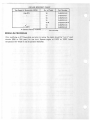
GASOLINE/OIL RECOMMENDATIONS ALL MERCURY SNOWMOBILES
(Atwch Bulletin Reference Sticker to Page 1-6 of Your Snowmobile Service Manual.)
IMPORTANT: Supersedes all information previously published on gasoline/oil recommendations: Service Manual, Operation and Maintenance
Manuals, Snowmobile Service Bulletins and "Fuel Warning Tags- Posters".
Fan Cooled and Free-Air Models
Fan Cooled
Recommended Oil(s)
Ratio (1)
Free-Air
Gasoline (2)
Ratio
Gasoline (3)
Quicksilver Snowmobile
50:1
Regular
20:1
Quicksilver Formula 25
50:1
Leaded
20:1
100/130
Quicksilver Formula 500
50:1
Minimum 86
20:1
AvGas
Quicksilver Formula 50
50:1
Average Octane
20:1
40:1
(80 Motor Octane)
20:1
BIA!TC-W Rated
(1) Ratio of 25:1 is required for the first (one) tank-full during engine "Break-In" period and/or
for "Severe Service" operation. Refer to ;,/Operation and Maintenance Manual" for ;,/Severe
Service" definition.
(2) For 1975 Model440 TIT (Below CHASSIS Serial No. 4210250), use PREMIUM, UNLESS
ignition timing is retarded from .095" BTDC to .080" BTDC.
(3) For Racing, use 100/130 AvGas and retard ignition timing from .100" BTDC to .080"
BTDC. For Trail Ride, use PREMIUM and retard ignition timing from .100" BTDC to .060"
BTDC.
Liquid Cooled Models
Liquid Cooled
Recommended Oil(s)
Ratio
Quicksilver Formula 50
20:1
Quicksilver Snowmobile Oil
16:1
Quicksilver Formula 500
16:1
BIA!TC-W Rated
16:1
Gasoline
100/130 AvGas
IMPORTANT: Some 1976 S/T "Operation and Maintenance Manuals
(C-90-74530)" recommended Quicksilver Snowmobile Oil, Quicksilver Formula
500 and BIA!fC-W Oils (all prediluted) at a 20:1 ratio. Use of these prediluted
oils, ONLY, at a 16:1 ratio are permissible. CHANGE any of these Manuals to
the above recommendation (16: 1 ratio).
TIIEI#'L ZIN'Y
~I:KYI~~
BULLETIN n
~~P.J
6 .....
~-=·
oe wt"•"d""'
-KO
A.
B.
C.
D.
r: /tS-TzDate
: 12/15n5
SNOWMOBILES
CIRCULATE
TO:
SERVICE MGR.
PARTS MGR.
MECHANICS
Place in Your
"Service Bulletin!
Binder
Balancer Installation- 1976 Model340 Strand 440 Str Snowmobiles
Drive Clutch Weights- AU 1976 Model340 Str
Drive Outch Weights- AU 1976 Model440 Str
Lower Cowl and Snow Flap Fasteners· All1976 Model250-340-440 Sno-Twisters
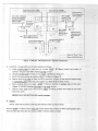
A. BALANCER INSTALLATION - 1976 Model 340 S(f and 440 S/T Snowmobiles
(Attach Bulletin Reference Sticker on Section 2C In.dcx Page of Your Snowmobile Service Manual.)
For ALL 1976 Model 340 S(f (CHASSIS Serial No. 4495560 and Above)
For ONLY 1976 Model440 S(f (CHASSIS Serial No. 4349537 and Below)
IMPORTANT: ALL 1976 Model250 SIT already are equipped with the balancer.
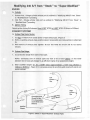
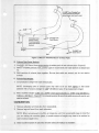
ALL 1976 Mercury Sno-Twister Snowmobiles MUST BE equipped with a balancer (steel disc .156"
[ 3.96mm] thick by 5.250" [l3.34cm] diameter) between the rewind starter cup and lower pulley.
The balancer (D-75961) stabilizes the crankshaft and prevents excessive vibration of the drive
clutch, thereby improving the life of drive clutch components.
IMMEDIATELY notify owners of the above specified Sno-Twister Snowmobiles that this balancer
MUST BE INSTALLED (installation instructions following).
IMPORTANT: A simple visual inspection via the water pump belt channel in the bell housing
can verify whether-or-not the balancer has been installed.
Order the required quantity of balancers and 4 screws for each balancer from your parts
distribution source. Credit for the balancers. screws and 0.3 hrs. labor per snowmobile will be issued
upon receipt of a completed warranty claim. One warranty claim (listing individual CHASSIS Serial
Nos.) may be used to cover service to all snowmobiles.
C-75961
C-10-75967
Balancer (1 per Snowmobile}
Screws (4 per Balancer)
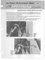
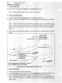
INSTALLATION INSTRUCTIONS
l. Remove rewind starter assembly.
2. Remove 4 screws which secure rewind starter cup and lower pulley to rotor. RETAIN the 4
lockwashcrs from the screws and discard the screws.
3. Inslall balancer between lower pulley and starter rewind cup.
IMPORTANT: Failure to use the 4 lockwashers on the 4 NEW retaining screws will result in
damage to the rotor and could alter ignition timing.
a. Place MACHINED side of balancer against lower pulley (toward engine).
b. Install lockwashers (retained in Step 2) on 4 NEW screws, apply Loctite Type "A"
(C-92-32609) to threads of screws and reinstall starter rewind cup with screws.
4. Reinstall rewind starter assembly.
(OVER)
B. DRIVE CLUTCH WEIGHTS- ALL1976 Model340 SIT
(Attach Bulletin Reference Sticker on Section 2C Index Page of Your Snowmobile Service Manual.)
ALL 1976 Model 340 Sff Snowmobiles MUST BE equipped with #135 weights (D-71737) in the
drive clutch assembly (6 weights per clutch). Some 340 SIT Snowmobiles (CHASSIS Serial No.
4495867 and Below) were shipped from the factory with #106 weights in the drive clutch, and
these ARE NOT LEGAL for "Stock II" class racing. To remedy, IMMEDIATELY notify owners of
1976 Model 340 Str Snowmobiles to check the drive clutch for correct #135 weights.
INSPECTION PROCEDURE
l. Part No. stamped into perimeter of drive clutch cover, as follows:
INCORRECT: XXXX 088
CORRECT
: XXXX-988- or XXXX-989088
088
2. OR, visual inspection of the Part No. on the weights thru vent holes in drive clutch cover, as
follows:
INCORRECT: XXXX 106 (Color- Red)
CORRECT
: XXXX 135 (Color- Black)
IMPORTANT: If the weights are incorrect and must be replaced, REMOVE the drive clutch
assembly from the engine before attempting clutch disassembly. Removal and/or installation of
the drive clutch~ works best -· with the aid of an arbor press.
Credit for the weights and 0.5 hrs. labor per snowmobile will be issued upon receipt of a completed
warranty claim. One claim (listing individual CHASSIS Serial Nos.) may be used to cover service to
all snowmobiles.
D-71737
Weight- #135 (6 per Clutch Required)
C. DRIVE CLUTCH WEIGHTS- ALL1976 Model440 SIT
(Attach Bulletin Reference Sticker on Section 2C Index Page of Your Snowmobile Service Manual.)
ALL 1976 Model 440 Sff Snowmobiles MUST BE equipped with #106 weights (D-71717) in the
drive clutch assembly (6 weights per clutch). Some 440 SIT Snowmobiles (CHASSIS Serial No.
4349543 and Below) were shipped from the factory with #123 weights in the drive clutch, and
these ARE NOT LEGAL for "Stock ill" class racing. To remedy, IMMEDIATELY notify owners of
1976 Model440 SIT Snowmobiles to check the drive clutch for correct # 106 weights.
INSPECTION PROCEDURE
l. Part No. stamped into perimeter of drive clutch cover, as follows:
INCORRECT: XXXX 089
CORRECT
: XXXX -989089
2. OR, visual inspection of the Part No. on the weights thru vent holes in drive clutch cover, as
follows:
INCORRECT: XXXX 123 (Color- Yellow)
CORRECT
: XXXX 106 (Color- Red)
IMPORTANT: If the weights are incorrect and must be replaced, REMOVE the drive clutch
assembly from the engine before attempting clutch disassembly. Removal and/or installation of
the drive clutch cover works best -- with the aid of an arbor press.
Credit for the weights and 0.5 hrs. labor per snowmobile will be issued upon receipt of a completed
warranty claim. One claim (listing individual CHASSIS Serial ~os.) may be used to cover service to
all snowmobiles.
D-71717
Weight- #106 (6 per Clutch Required)
D. LOWER COWL and SNOW FLAP FASTENERS- ALL 1976 Model 250-340-440 Sno-Twister
Snowmobiles
(4ttach Bulletin Reference Sticker on Section 2F Index Page of Your Snowmobile Service Manual.)
LOWER COWL
To be sure that the lowf'r cowl remains securely fastened to the front crossmember, we recommend
that th<> 6 aluminum rivets, which secure the cowl to the front crossmember (silver colored, 5/8"
diameter head - 3 located inside lower cowl in a line on each side of crossmember), be replaced with
STEEL rivets (Mercury Part No . C-17-76047) or an equivalent steel rivet (3/16" [4.8mm] diameter
shank X 5/8" [15.9mm) diameter head with 3/8" r9.5mm) toY:!" [12.7mm] grip range).
SNOW F LAP
Check the rivets which secure the snow flap and mounting strip to the chassis. To prevent the rivet
from pulling out thru the snow flap, make sure that the "clinch" end of the rivet (inside the tunnel)
has a "backing" washer on <>ach rivet (Mercury Part No. C-12-21273) or an equivalent washer
(13/64" [5.16mm] J.D. x Y2" [l2.7mm] O.D. x l/16" [l.59mm] thick).
If the rivets arc not equipped with these backing washers, remove and install new rivets (C-17-64817
or equivalent) with the backing washers.
0
0
0
.J'
Number: 76-13
TIIEH
~I:KY l\;1:
BULLETIN I ~
Date
: 12/22/75
SNOWMOBILES
~!!",&
SERVICE MGR.
CIRCULATE
TO:
701.11 Ul\lf•I'IC•
of <WI$l.nd1t19
.......
PARTS MGR.
Place in Your
"Service Bulletins
Binder
MECHANICS
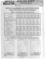
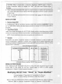
MERCURY SNOWMOBILES with ARCTIC DRIVE CLUTCH
Internal Drive Clutch Component Information
"Stock" Drive Clutch Component Chart
MODEL NAME
1975
340 srr
1975
440S/T
1976
340 TIT
1976
440 TIT
1976
25o
srr
1976
340S!T
1976
440 srr
CHASSIS Serial No.
Below
4207500
Below
4206250
Below
4347125
Above
4347124
Below
4495560
Above
4495559
4349324
MERCURY PART NO.
Above
D-52-71571 D-52-71572 D-52-74255 D-52-74256 D-52-75098 D-52-75099 D-52· 75100
LAST 3 DIGITS of NO. STAMPED ON
OUTSIDE of DRIVE CLUTCH COVER
DRIVE CLUTCH SPRING
061
062
077
080
081
088
089
Blue
Blue
Blue
Blue
Green
Green
Green
No. of Turns
3.9
3.9
3.9
3.9
5.0
5.0
5.0
Mercury Part No.
C-24-71517 C-24-71517 C-24·71517 C-24-71517 C-24-74992 C-24-74992 C-24-74992
Color
DRIVE CLUTCH WEIGHTS
Color
Red
Black
Red
Yellow
Red
Black CD
0146·106
0146·135CD 0146-106
Red
5.958g
4.479g
5.958g
0.530"
0.471"
0.530"
No. Stamped on Weights
0146·106
0146·105
0146-106
0146-286
Gram Weight
5.958g
7.858g
5.958g
8.800g
Outside Diameter
0.530"
0.598"
0.530"
0.629"
Mercury Part No.
D-71717
D-71716
D-71717
D-74125
D-71717
D-71737 CD D-71717
No. Stamped on Ramps
None
None
292
293
None
None
None
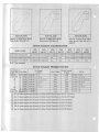
Drawing of Ramp Profile
Figure 1
Figure 1
0
Figure 3
Figure 4
Figure 5
Figure 6
Figure 6
Mercury Part No.
D-71496 (!) D-71496
(!
D-74123
D-74124
D-75908
D-75177
D-75177
DRIVE CLUTCH RAMPS
CD
Q)
0
Optional Clutch Ramps (D-74857A 1, Figure 2) are available for trail riding.
A few 1976 Model 340 SIT snowmobiles were shipped from the factory with INCORRECT
drive clutch weights. Weights stamped 0146-135 (D-71137) MUST BE INSTALLED in these
clutches.
:..
-
:
'
/
·'
/
/
l
ACTUAL SIZE
Figure 1. D-71496 Drive Clutch
Ramp Profile (1975 340 S/T &
440 S/T)
ACTUAL SIZE
Figure 2. D-74857A1 Drive
Clutch Ramp Profile (Trail Ramp
for 1975 340 S/T & 440 S/T)
(OVER)
J
ACTUAL SIZE
Figure 3. D-74123 Drive Clutch
Ramp Profile (1976 340 T/T)
ACTUAL SIZE
ACTUAL SIZE
ACTUAL SIZE
Figure 4. D-74124 Drive Clutch
Ramp Profile (1976 440 TIT)
Figure 5. D-75908 Drive Cluttch
Ramp Profile (1976 250 SIT)
Figure 6. D-75177 Drive Clutch
Ramp Profile (1976 340 SIT &
440 SIT)
Drive Clutch Accessories
MODEL NAME
Drive Clutch Elevation Kit
1975
340 SIT
1975
440S/T
1976
340 TIT
1976
440 TIT
1976
250 SIT
1976
340 S/T
1976
440SIT
D-71712A1 D-71712A 1 D-74124A 1 D-i11716A 1 D-71712A2 D-71712A2 D-71712A2
Drive Clutch Modification Kit D-71711A 1 U-71711A 1
N.A.
N.A.
Drive Clutch Trail Ride Kit
N.A.
N.A.
D-74857 A 1 D-74857A 1
D-71711A2 D-71711 A2 D-71711A2
N.A.
N.A.
N.A.
N.A. - Not Available
Drive Clutch Weight Chart
I
Full Throttle
Gram Weight
Engine RPM
Increase
Engine RPM
Decrease
Engine RPM
light 3.058g
No. Stamped
on Weight
0146-108
3.725g
0146-175
4.479g
0146-135
4.958g
0146-107
5.958g
0146-106
6.992g
0146-123
7.858g
0146-105
Heavy 8.800g
0146-286
CD0
CD0CD
CD0CDCDCD
CD CD CD
CDCD
CD0CD
CD
0
Color of Weight
Outside Diameter
of Weight
Yellow
0.406"
Red
0.437"
Black
0.471"
Part No.
CD 0
D-71735 CD 0 CD
D-71737 CD 0 Q) CD CD
D-71736 Q) CD CD
D-71717 CDCD
D-71734 CD0CD
D-71731
White
0.491"
Red
0.530"
Yellow
0.568"
Black
0.598"
D-71716
Yellow
0.629"
D-74125
Q)
@
Six of these weights are included in Drive Clutch Modificat~on Kit (D-71711 A 1).
G)
Six of these weights are included in Drive Clutch Elevation ,Kit (D-71712A 1).
Q)
(D
Six of these weights are included in Drive Clutch Elevation Kit (D-71712A2).
Six of these weights are included in Drive Clutch Modificat~on Kit (D-71711 A2).
Six of these weights are included in Drive Clutch Elevation Kit (D-71716A 1).
CD Six of these weights are included in Drive Clutch Elevation Kit (D-74124A 1).
CD
0
5NU•TWISTER TIPSTER
HI-PERFORMANCE NO. 74-1
(Flash 'Inside' Info for Mercury Snowmobile Dealers to Z-i-p to
Their Sno-Twister Customers) 11/16n3
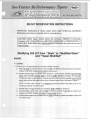
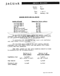
INTRODUCTION
It's official! After months of spinning on hay and straw, or on just plain grass, the snowmobile
season - on good old Alaskan snow - has opened with a resounding "Margin for Mercury". Eager
sponsor of the kick-off race meeting on Nov. .3rd and 4th was Brandt's Lodge ... and, if you're real
quick in geography, you'll find it 160 miles northeast of Anchorage. Give or take a couple of
months, that can be real mean blizzard territory. Ignoring all impending hazards, however, were
local drivers who had "WIN" written all over their Sno-Twisters.
The Sno-Twisters leaped to the front and stayed there to win all three heats in their 400 class, plus
the final around the oval, all on Saturday. Then Sunday the crew came right back to grab first place
honors in cross-country.
So, here's the bonus! We, of course, are happy to share the secrets of success so that you, too, can
make the run for the roses. The following procedures were used in setting-up the champion
Sno-Twisters at Brandt's Lodge:
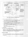
ENGINE
1. Check timing @3000 RPM .100" .±. .005" BTDC.
2. Adjust idle slow enough to allow clutch to reset. (Too high idle speed will cause partial
engagement and belt drag, resulting in a slower start off the line.)
3. Check for proper jetting.
The following jet sizes will serve as a guide, however, a proper plug check is the only way to get
spot-on for racing . A Champion N55G plug is easier to read and is suitable for racing. (After 100 yd.
full throttle speed run, the correct fuel/air mixture will cause plug electrode to have a light
chocolate brown color- must never appear whitish/grey.)
2000' to 4000' ELEVATION
BELOW 2000' ELEVATION
Temperature
Jet Size
Above 300
3QO
290 to 300
320 to 330
Below oo
330 to 360
0.
Subtract 10 from the jet sizes I isted on left.
If your Mercury dealer doesn't have jets, try any dealer stocking Mikuni carburetor parts. If all else
fails, a #53 drill (.059 dia.) corresponds to a 320 jet, and a 1/16 drill (.0625 dia.) corresponds to a
340 jet.
Move jet needle to richer position by one notch; i.e. the retaining clip should be moved to the
fourth (4) notch from the top of the jet needle.
DRIVE SHEAVE
1. Inspect clutch and lube per instructions in the Owners "Operation and Maintenance Manual"
(C-90.68019).
2. Check engagement RPM and adjust if necessary.
3. Use an accurate tachometer to check engagement speed. (USSA says 4000 RPM max.)
(OVER)
DRIVEN SHEAVE
1. Check alignment per the manual.
2. Set spring preload at 2 full cams.
3. US!: A NEW BELT.
4. Adjust belt tension per the manual.
FUEL OIL
Use a 20:1 fuel-oil mix. Only the following oils are known to be satisfactory for SNO-TWISTER :
Mercury Formula 25
Mercury Formula 50
Mercury Formula 500
Castrol Synthetic High Performance Snowmobile Oil
NOTE: You may want to clamp or wire the fuel lines at the fuel pump.
ICE STUDS and CARBIDES
Carbide wear skegs (D-68440) must be installed for racing. The ski holes may need to be drilled out
and an oversize washer used above the ski to make the carbide fit properly.
Ice studs (D-68441) must be installed on the track. A good starting point is to install eleven studs
on each side, utilizing the holes in the track bars. One or two additional rows of eleven can be added
in the center band of the track but should be attached to the rubber only, not thru the bar. Use
washers to space the studs up to the 3/8" allowable.
You may prefer to set the steering in the low effort position, since the carbides increase the steering
effort considerably. See your "Operation and Maintenance Manual".
SLIDER/TRACK ADJUSTMENT
The track must be adjusted for proper tension as outlined in your Owners Manual. The track will
run smoother if the drive sprockets are lubricated with grease (STP works well). Most of the side
load is taken out through the wear plates inside the tunnel, so be sure to lubricate the edge of the
track.
As outlined in your Owners Manual, handling (oversteer and understeer) can be adjusted. We found
that for best weight transfer, the rear springs should be set soft and the front springs in the %
position. Set yours up and test prior to racing.
TETHER SWITCH
Disconnect on-off switch wire from #3 stud of terminal block, to prevent accidentally stopping the
engine.
Attach a paper clip to the tether switch cord and hook the clip on the throttle cable so that the clip
must be pulled free before the tether is disconnected.
Check the tether switch operation. Moisture will cause the points to freeze, resulting in a switch
malfunction. Gasoline de-icer will eliminate the moisture.
COWL
The aluminum hinge rivets should be replaced with large head steel rivets or bolts. The headlight
should be removed or taped and the screws secured with silicone sealer.
**IMPORTANT NOTE: U.S.S.A. has ruled that
we cannot use the boggie wheel kits for racing.
Sno-Twister IHi-Performance Tipster
No. 75-1 (6/1174)
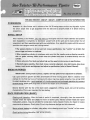
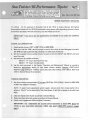
Important Info about Snowmobile Registration and
Sno-Twister/Hi-Performance Tipster Mailing List
Mercury Marine is introducing another FREE customer benefit: Owner direct mailing of the new
"Sno-Twister/ Hi-Performance Tipster", aimed primarily for racing machines.
To get the project in gear, the following "IMPORTANT" Tipster mailing list directive will be
included in the "Snowmobile Information" envelope shipped with all Mercury Snowmobiles
manufactured after Sept. 1, 1974.
IMPORTANT
MR. DEALER - Mercury Marine has made an important change to Snowmobile
Registration Cards. We've added RACING0to the "Primary Use" section of the card.
We've done this in response to many requests from owners (primarily use their
snowmobiles for racing) who wish to receive, from the factory, owner direct mail of latest
information in "Sno-Twister/Hi.Performance Tipster" bulletins on racing.
To compile such a customer mailing list via direct computer mailing, it is ESSENTIAL
that 1) you fill out all registration cards, 2) you ascertain from the owner the primary use
intended and mark the registration card accordingly and 3) you promptly mail all cards to
the factory.
We're sure that every racing owner will want to take advantage of this FREE. direct mail
service.
Only you can get him on the racing "Tipster" list! If he races, check RACINGD.
C-90-71050 (5174)
We'll also advise owners in their "Operation and Maintenance" manual that, if racing is intended, it
should be properly checked on the new machine's Registration Card under RACING
0
so that
the customer will be mailed the "Tipster" bulletin.
This "Tipster" sheet will be used exclusively to notify owners of high performance information and
time-saving tips.
IMPORTANT: The service is intended strictly as an owner benefit. Dealers still will receive
an identical mailing at the same time.
Sno-Twister IHi-Performance Tipster
NOTICE: Sno-Twister/Hi-Performance "Tipsters" are in numerical
order, starting with 75-1. If the first copy you receive is (example)
75-3 •· and you desire previous "Tipster" issues (75-1 and 75-2) advise Mercury Marine Publications Dept., P .0. Box 1108, Fond du
Lac, WI 54935. and give the first number that you received.
No. 75-2 (11 120174)
1975 SNO-TWISTER- (340 S(T- 440 S(T)- COMPETITION SETUP INFORMATION
POSSESSION
Possession of a Sno-Twister well in advance of the '74-'75 racing season can be a very big assist. It gives
the driver ample time to get acquainted with the sled and to properly break it in before entering
competition.
INITIAL SETUP
After receiving a Sno-Twister, you may want to thoroughly check the engine assembly and possibly
even disassemble it completely to familiarize yourself with all the parts and to make certain that all
components and their assemblies meet with your satisfaction. If so, rebuild the engine with the care and
precision that a surgeon would use. It brings results!
• Pay special attention to all nut and bolt torque specifications. Use "loctite" on all bolts that
secure trigger and stator to crankcase.
• When assembling cylinders to crankcase, make sure that the transfer ports are lined up correctly,
with no gasket overhang. Make certain that the cylinder head dome is centered directly over the
cylinder.
• Check carburetor float levels and adjust high and low speed mixture screws to specifications.
• Reinstall engine assembly, then check torque converter alignment, drive belt tension, drive chain
tension, track tension and alignment and adjust to specifications (refer to Owner's Manual).
BREAK -IN PERIOD
IMPORTANT: During break-in period, a slightly rich high speed mixture adjustment is advisable.
Use a good premium gasoline and Mere Snowmobile Oil when mixing gas/oil. Make it a slightly richer
mixture for the first few hours of running (until piston rings have seated properly). Run at high RPM
for short durations only --avoid sustained full throttle operation and prolonged operation at a constant
throttle setting. Check spark plugs often to ensure that engine is not overheated.
Become familiar with the feel of the sled (clutch engagement, shifting, sound, etc) and its handling
characteristics. This is very important for later testing.
RACE PREPARATION (BASIC)
Cleaning and Inspection: After the break-in period is completed, thoroughly clean the snowmobile.
Visually check the engine and chassis for worn or broken parts. Remove cylinder heads and inspect
head gaskets, pistons, rings and cylinders for excess wear, cracks, chipped chrome, etc. Repair or replace
components as necessary. Check piston fit and ring clearances (end gap and side clearance).
Secure exhaust headers to cylinders, using safety wire or bearing mount type "Loctite" on hex screws.
Check ignition timing (should be .100" BTDC [21%0] ).
Check ski alignment (parallel, measuring front and rear of skis). For easier (slower) steering, use the tie
rod attaching hole closest to the steering shaft. Try both positions for your preference.
Check track and suspension: Track tension and alignment, suspension cross shafts (wear/bending lubrication), shock absorbers (dampening/leakage), idler wheels (wear and free bearing movement), slide
wear bars and chassis rub strips. Check all nuts and bolts for wear and proper torque. Repair or replace
parts as necessary.
Chaincase: Clean and inspect chain, sprockets, jackshaft and bearings.
Check brake assembly (cam, pin and pucks for wear) "free floating" and correctly adjusted.
RACE PREPARATION (FINAL)
Check electrical wiring: Disconnect emergency stop switch (red switch on throttle control) from
terminal block (located behind dash). Be sure that ground wire from CD mounting base to engine is
secure and in good condition. Red wire from electronic pack connects to PTO side coil; white wire
connects to coil on rewind side. Make certain that CD wiring connectors are coupled securely.
Install a "race-proven" ignition safety stop switch (tether switch) to suit rider. Check and adjust
carburetion; re-check carburetor float levels. Adjust high speed mixture needles (as outlined in Owner's
Manual) to suit conditions (temperature and elevation) that will be encountered. Synchronize throttle
slides and adjust idle speed, making sure full throttle operation is attained and throttle cable moves
freely. Check all fuel lines and hoses. Be positive that the lines are secure on fittings and not pinched or
crimped.
Check exhaust system: Inspect for cracks, broken parts and missing coupler springs. Make certain that
system is mounted securely.
Drive sheave (clutch): disassemble and clean. Check fiber bushings in movable and fixed sheaves for
wear and/or binding. Check all moving parts for wear and restricted movement. Make sure that ramps
are properly seated in movable face. Engagement RPM can be raised by adding spacers on spring or
lowered by removing them. No more than four (4) spacers are allowed. When reassembling drive sheave,
be sure to match alignment mark on movable sheave with mark on sheave cover and take care not to
bind fiber bushing- no lubrication is necessary.
Driven sheave: Disassemble and clean. Check condition of torque bracket wear plates. Replace if
necessary. Reassemble and lightly lubricate shaft and wear plates. Adjust return spring preload as
required (approximately 2 ramps) to attain maximum recommended RPM at wide open throttle
(8250 RPM) - refer to Owner's Manual.
Torque converter alignment: Check and adjust alignment (parallel and offset distance between sheaves).
Inspect drive belt for wear, distortion, burn spots and cracking. Check drive belt tension. If in doubt
about condition of belt, replace it- refer to Owner's Manual.
Drive chain: Drain and refill chaincase with 3 oz. (3.1 imp. oz.) of automatic transmission fluid (ATF).
Check and adjust chain tension to specifications.
Suspension adjustments: Understeer and oversteer can be varied by changing spring tension on front
cross shaft. Rear shocks can be adjusted for firm or soft ride, depending upon rider preference. Best
weight transfer requires a soft settin9 at rear- refer to Owner's Manual.
Track/slide suspension alignment: Align track first to slides, then to chassis tunnel.
NOTE: Because the front control arm always is in compression, it may be necessary to rework the
suspension mounting holes slightly and adjust alignment with the suspension bolts loose in order to
achieve perfect alignment of the slider suspension inside the chassis tunnel.
Traction devices: Three types of studs are available from Mercury Marine for various types of racing
surfaces and conditions.
Mere Stud (22 Pes. Per Package)
Mere Scat Stud (22 Pes. Per Package)
Mere Carbi•tle Stud (22 Pes. Per Package)
D-68441
D-71925
D-71926
Placement and pattern are strictly rider preference, depending upon rider style and racing surface. The
rivet in the outside ends of each track bar can be removed, if absolutely necessary, to place a stud.
Track lubrication: Lubrication of the track can be beneficiial by reducing drag between track and sides
of tunnel and between drive sprockets and track. (STP lubri•cant works well.)
Skis/carbide wear skegs: Carbide wear skegs are a MUST for stock racing and are available from Mercury
Marine.
D-68440-1
D-71334
Carbide Sk•eg {Pair- 10" Carbide Inserts)
Carbide Sk•eg (Pair - 6" Carbide Inserts)
Badly chipped, bent or broken carbide skegs should be replaced immediately. Placement and length of
carbide skegs influence handling to a high degree and, again, are mostly rider preference.
Special application: At this time, the following equipment is available from Mercury Marine for special
application; i.e., high elevation, cross country racing and modified racing:
D-1393-5872A1
D-1393-5854A1
D-71712A1
D-71711A1
C-58601A1
High Eleva1tion Carburetor Kit - 340 S/T
High Eleva1tion Carburetor Kit • 440 SIT
High Eleva1tion Drive Sheave Kit - 340 SIT and 440 S/T
Modified Drive Sheave Kit- 340 SIT and 440 SIT
Bogie WheEl! Kit - 340 SIT and 440 SIT
Driver Sprockets {340 SIT and 440 SIT)
(1) D-69757-12
D-68439
D-64684
D-63318A 1
D-64131
12 Tooth
13 Tooth
14 Tooth
15 Tooth
16 Tooth
prive Chain {340 SIT and 440 S/T)
(2)1 D-71483
78 pitch length
(2)1 78 pitch chain must be used with 16 tooth
sprocket.
(1) One C-23-69842 spacer must be used with 12 tooth sprocket.
CONCLUSION
The aforementioned steps have touched basically on major aspects of setting up a 1975 Mercury
Sno-Twister for competition. Hard work, patience, thorouuhness and a strong desire to win can-- and
will-- produce a competitive Sno-Twister that will win consistently.
-
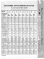
MERCURY MARINE - CERTIFIED SNOWMOBILE SPECIFICATIONS
NOTE: All length Measurements Are in Millimeters, unless Specified
Inches (");All Volume Is in Cubic Centimeters (Conversion Table Below).
MODEL NAME
ENGINE SPECIFICATIONS
Engine Manufacturer
Engine Model
1975
340 S/T
1975
440S/T
1975
340 S/R
1975
440 TIT
1975
440 M/ X
1975
440 S/R
Kohler
Kohler
Kohler
Kohler
Kohler
Kioritz
Kioritz
Mercury
K340-2RS
K440-2RS
K440-2RS
K340-2AX
KEC-440/22
KEC-440/22
Markll
644
2
2
2
2
2
2
Engine Displacement
398.2
339.3
429.4
435.8
338.1
437.9
2
437.9
2
Type of Cooling
FA
FA
FA
Fan
Fan
Fan
Fan
Bore
65.0
60.0
67.5
68.0
62.0
66.0
66.0
Fan
79.37
Stroke
Ignition
60.0
CD
60.0
CD
60.0
CD
60.0
CD
56.0
Mag
64.0
Mag
64.0
Mag
65.07
CD
Min. Compressed Head
Gasket Thickness
Min. Compressed Base
Gasket Thickness
0.95
1.2
0,7
1.1
1.2
1.1
1.1
N.A.
0.35
0.3
0.3
0.3
0.3
0.3
0 .3
N.A.
19.0
14.7
19.0
21 .7
17.7
21.4_±5%
21.4:!_5%
28.5
Crankcase Volume
290.0
305.0
305.0
630.0+10%
463.0+10%
931.0+10%
931.0+10%
N.A.
Overall Length of Cylinder
Depth -Top of Cylinder
to Bottom of Intake Port
Depth· Top of Cylinder
to Top of Exhaust Port
Depth- Top of Cylinder
to Top of Transfer Port
No. of Transfer Ports
109.0+0.01
109.0±.5
109.0+.5
109.0 + .1/-.2
98.3+.2
115.95+.5
115.95+.5
174.62
90.5
90.Q±1.5
95.3±1.5
92.0+.75/-1.0
84.3+.75/-1.0
Reed Valve
Reed Valve
Boost • 53.08
Width of Transfer Ports
Spark Plug Hole
~
~
1975
Markll
K400-2RS
No. of Cylinders
~~olume of Head to Top of
I
~
!;'t~a~
:;16:-"c;
!' -· w .....
~~g:Sl~
~;:; o.;t,g>
t:~~.g 9
....
C~-t
::l 3: ~ ... ~
0. 91
::r -·
~- i' a· C3l ~
i
~
::l
i...
~
,..
g.~
i
g ..
""'"0 ...
~< ~
.. ~ ~-< 'tl
..
0 0~
<.
'"e'"
Og'tn-.~
34.43+ .4/-.6
37.5_±1.0
37.5_±1.0
39.11
47.0
46.25±1.5
46.25.:!:,1.5
47 .8+ .6/·1.2
43.8+ .6/-1.2
51.5.:!:,1.0
51.5.:!:,1.0
50.80
c
-lll :
~ )( ~ !2. !l
4
4
4
2
4
4
2
[
32.0/11.7
33.0.:!:,1.5/
12.5±1.0
4
33.0+1.5/
13.0;!:1.0
35.0+1.0/
13.7+1.0
27.0.:!:,1.0
85.0_±2.0
85.0.:!:,2.0
Width of Intake Ports
Width of Exhaust Ports
46.0
40.0
45.0+1.5
37.0;!:1.5
43.0+1.5
43.0±1.5
48.0+1.0
42.4+.75
37.0+1.0
37.0+.75
Reed Valve
40.0+1.0
Height of Transfer Ports
13.0
14.0+1.0
14.0+1.0
13.7+1.0
14.0:!:_1.0
Height of Intake Ports
Weight-Piston Assembly
Complete
Overall Height of Piston
29.0
28.5+1.0
30.3+1.0
24.0+.5
22.5+.5
300gr.:!:,20gr
240gr;!:10gr
310gr;t10gr
335gr;t10%
71.7
67.5+.55
70.7+.5~
No. of Rings per Piston
Ring Type
1
L-Ring
1
1
Dykes Keystone
Ring Thickness
Crankcase Face to Center
of Crar>kshaft
Main Bearing Type
2.0
2.0+.08
70.0
70.0±.5
Sealed-Ball
Sealed-Ball
.. -· :;·
35.05
0
'-J: 3
Reed Valve
40.0+1.0
Reed Valve
47.0
1\.)'tl -·
o.-&f.l
C I--
13.5+1.0
13.5+1 .0
Reed Valve
Reed Valve
20.32
Reed Valve
240gr;!:10%
307gr±10%
307gr:!:_10%
491.68gr
71.7+.5
64.1+.5
71.42+.5
71.42+.5
75.41
2
2
Dykes Keystone
2
"L" & Rectangular "L" & R,ectangular Rectangular
2
Rectangular
3
Cast Iron
2.5+.08
2.0+.08
2.0+.08
1.5+0.1
1.5+0.1
1.57
~
70.0;!:.5
70.0±.2
58.0;!:.1
70.23±.2
70.23;!:.2
1-Piece
"""'
i\;
Sealed-Ball
Sealed-Ball
DBA Level
Mercury
82+2
ACS
82+2
Cowl
82+2
Sealed-Ball
Cowl
82+2
Mercury
82+2
Head Pipe Length
98.5
117.0+2
167.6+2
"Y"-Manifold
24.5"+.25"
15.25"+.25"
15.25";!:.25"
127.0
Piston @ TDC
4\):::.:...~CD
0
Sealed-Ball
Sealed-Ball
~
~.
Q
~ ~.:;;
33.5+.4/-.6
Sealed-Ball
~
g -4:!: 3
3 "'O'tl-· :a g:n
.!.'%
. .,..
co!!:<:;;~
29.0_±1.5
Mercury
82+2
~
~
~
Cl)
29.5_±1.5
Mere/Donaldson Mercury
82+2
82+2
~·
:. c:r o· ... 1
g. -o-a
c ;
30.0
Muffler Make
<D
1974
SNO-TWISTER
00::~"'
• . , 0. ;;;
g
&_1,113~
.~
~
I
~
~
~
~
~
~
~
~
~
~
...........
~
.........::
(I)
CARBURETOR
Make/Model No.
No. per Engine
MikuniNM·36
Mik uni/36/34RS
Mikuni/36/44RS
MikuniNM·36
Walbro/WDA·50
Walbro/WDA-47
Walbro/WDA-47
2
2
2
2
1
1
1
2
36.0
36.0
36.0
39.7
39.7
39.7
32.5
36.12
36.12
36.1
41.3
4 1.3
4 1.3
38.1
Yes
Yes
Yes
Yes
Yes
Yes
Yes
Arctic Cat/
XXXX-062
Salsbury/850
Venturi -Smallest
36.0
Diameter in Throat
Throttle Bore - Largest Dia. 37.0
Downstream of Butterfly
Choke
Yes
DR IVE CLU TC H
Make/Model No.
Comet/100C
Arctic Cat/
XXXX-061
Engagement Speed
3800-4000 RPM
2)
No. of Springs/Color
Spring Wire Diameter
Walbro/WRA-3
Salsbury/850
Salsbury/850
Mercury
Salsbury/850
3500 RPM+10%
3500 RPM+10%
3400 RPM+10%
3200 RPM+10%
1/Red
4000RPM Max. 2)4000 RPM Max. 3300 RPM+10%
1/Piain
1/Biue
1/Blue
1/Piain
1/Piain
1/Piain
1/Piain
4.75
.192"
4.74
4.3
.192"
4.32
4.32
4.32
No. of Coi ls
4.8
3.9
3.9
5.4+.2
5.4+.2
5.4+.2
5.2+.2
5.4±.2
Arm/Roller Weight
38.6gr+.5gr
18gr+1.5gr
22gr+1.5gr
50.08gr+ .5gr
40.12gr+.5gr
43.86gr+.5gr
65.32gr+.5gr
51.32gr+.5gr
Comet/90D
Salsbury/152110
Salsbury/152110
Salsbury/850
Salsbury/850
Salsbury/850
Mercury
Salsbury/850
4.75
.192"
.192"
4.88
6.25
41°
6.25
41°
6.25+.2
3.96
5+.2
5.71
6
45°
3.96
5+.2
4.3
7+.2
350
320
32°
DRI VEN CLUTCH
Make/Model No.
Spring Wire Diameter
No. of Coils
Ramp Angle
CHASSI S/SUSPENSION
Chassis Model
6+.2
40°
32°
66769
70729
70729
72006
66602/70238
68345
69869
66011
Suspension
Slide Rail
Slide Rail
Slide Rail
Slide Rail
Bogie Wheel
Slide Rai l
Swing Frame
Chassis Length
Ski Length
1880+6.3
1000±6.3
117+3.1
2235+6
952.5+3
117 .6+1.5
2235+6
952.5+3
117 .6+1.5
2235+6
952.5+3
117.6+1.5
Slide Rail
2209.8+6
2247+6
2247+6
1008.4+3
1008.4+3
1008.4+3
2521
993.78
136.6+1.5
136.6+1.5
136.6+1.5
152.4
Ski Width
TRACK
Make
Goodyear
Goodyear
Goodyear
Goodyear
Goodyear
Goodyear
Goodyear
Mercury
Rubber/
Steel Bars
381.0+3/ -1.5
Rubber/
Steel Bars
381.0+3/-1.5
Rubber/
Steel Bars
381.0+3/-1.5
Rubber/Grouser
Rubber
Rubber/Grouser
Rubber
Width
Rubber/
Steel Bars
381+3.2
387.35
387.35
387.35
431.8
Length - 0 .D.
2820
2816.4+12.5
2816.4+12.5
3072.4
3327.4
9
3072.4
8
3009.9
9
2816.4+12.5
9
8
8
8
15
14
15
17
15
17
18
16
34
34
34
34
36
36
28
36
13-14-16
12-13-15-16-17
12-13-14-16-17
12-13·14-15-16-18 12-13-14 -16·17 -18 12-13-14-15-16-18 12-13-14-15·16·17 12·13·14-15·17 ·18
N .A.
N.A .
N.A.
28-36·38-40
28-34·38-40
28-34-38-40
34-36·38·40
28-34·38·40
360+10
365
365
365
350
390
380
500
Material
Track Drive Sprocket Teeth 9
CHAl NCASE
Standard Drive Sprocket
No. of Teeth
Standard Driven Sprocket
No. of Teeth
Optional Drive Sprockets
No. of Teeth
Optional Driven Sprockets
No. of Teeth
Snowmobile Weight(Pounds
METRIC CONVERSION: 1mm (millimeter) = 0.0394" (inch); 1 gr (gram) = 0.04 oz.;
1 cc (cubic centimeter) = 0.06 cu.in.; 1 1b. (pound) = 0.4536kg (kilogram)
NA. a Not Applicable
(D
0-4 Spacers (.06 Thick) to Achieve 4000 RPM Max.
Sno-Twister IHi-Performance Tipster
NOTICE: $no-Twister/Hi-Performance "Tipsters" are in numerical
order, starting with 75-1. If the first copy you receive is (example)
75-3 •• and you desire previous "Tipster" issues (75-1 and 75-2)advise Mercury Marine Publications Dept., P.O. Box 1108, Fond du
lac, WI 54935, and give the first number that you received.
No. 75-4 (11 122/74)
Driven Shaft Pillow Block - 1975 340 S(T, 440 SfT and 440 T fT Models
We have received a few reports that the driven shaft pillow block (D-71007) has developed a small
crack (as shown in Figure 1) because of the torque load and stress to which the block is subjected.
Thus far, complete breakage has not occurred.
At this time, and only as a temporary measure, we recommend construction and installation of a
support brace (as shown in Figure 2) to reinforce the block.
A new, stronger pillow block with a support brace is in process and will be available soon for
no-charge replacement. As soon as parts are available, details will follow in a later bulletin.
Figure 1.
Cracked
Pillow
Block
•
Support Brace
: Aluminum 14" Long
l"Wide
lja"Thick
Figure 2.
Support
Brace
Installed
09009
Sno-Twister IHi-Performance Tipster
NOTICE: Sno-Twister/Hi-Performance "Tipsters" are in numerical
order, starting with 75-1. If the first copy you receive is (example)
75-3 -- and you desire previous "Tipster" issues (75-1 and 75-2) advise Mercury Marine Publications Dept., P.O. Box 1108, Fond du
Lac, WI 54935. and give the first number that you received.
No. 75-5 (11 /22/74}
1974-75 "Race Proven" Set-Up Tips
It's official - On the weekend of November 2nd & 3rd, 1974, in Alaska, Mercury Sno-Twister
Snowmobiles kicked off the 1974-75 snowmobile racing season with resounding victories in Stock
nand Stock m classes. Here are some set-up tips that helped pull it off.
IMPORTANT: These set-up tips and specifications are intended for use under race conditions
ONLY!
ENGINE and CARBURETION
1. Check ignition timing (.100" ± .005" BTDC at 3000 RPM).
2. Make sure that idle RPM is set low enough to permit drive clutch to reset (disengage from belt).
Idle RPM too high causes belt drag, resulting in a slower start off the line.
3. Set the low speed mixture needles (air pilot screws) on both the 340 Sff and 440 Sff at 2 turns
open from seat.
4. Set carburetor jet needles as follows:
340 S{f- "E" ring in 2nd notch from top.
440 S/T- "E" ring in 1st (top notch).
5. Use the chart and graph in the Owners "Operation and Maintenance" Manual as a guide to
determine approximate setting of high speed mixture needles. However, POSITIVELY
determine final setting by "reading" spark plug color after making a few 100 yd. WOT runs
(refer to Owners Manual for procedure).
TORQUE CONVERTER
1. Set driven sheave spring preload at 2 full cams [30-32 lbs. (13.6-14.5kg)] . Check for 8250 RPM
at WOT and readjust if necessary.
NOTE: To assist future adjustments and/or repairs, remove burrs from torque bracket ID to
achieve a uslip fit" on the steel shaft of the fixed sheave. A light film of grease on the shaft also
helps.
2. Clean and inspect drive clutch as outlined in Owners Manual.
3. Check and adjust drive belt tension as outlined in Owners Manual.
4. Check clutch engagement RPM and adjust if necessary.
IMPORTANT: Use a dependable and accurate service tachometer to check RPM. Don't rely
strictly on your snowmobile tachometer. (USSA rules specify 4000 RPM maximum engagement.)
TRACK/SUSPENSION
1. Adjust track tension and alignment as outlined in Owners Manual.
2. Lubricate drive sprockets and both edges of track for smoother running with less drag (STP
works well).
3. For best results of weight transfer, set spring preload on rear shocks soft and set tension on
front suspension springs as test results on a particular track may dictate.
4. Check tightness of all fasteners regularly before each race, particularly bolts that secure the ski
pivot (saddle) to the leaf spring assembly and bolts which secure the ski assembly to the spindle.
TETHER SWITCH
Obtain and install a "race proven" Safety Tether Switch. Type of switch and mounting location are
strictly driver preference. (Safety Tether Switch IS NOT available from Mercury Marine.)
IMPORTANT: To prevent accidentally stopping the engine during a race, we suggest
disconnecting the emergency stop switch (red), located on the throttle control. (Remove orange
wire from No. 1 position on terminal block.)
TRACTION DEVICES
1. Carbide insert wear skeg (Mercury Marine Part No. D-68440-1) on the skis are a MUST for
racing.
2. The following "stud" patterns are typical of installations that performed very well on "hard
pack" and ice.
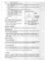
NOTE: Patterns shown are viewed from the bottom of the track, rear to front.
440 S/T
KEY
X = Mere Carbide Stud (Part No. D-71926- 22 pes. in pkg.) (Super Stud)
Z = Mere Scat Stud (Part No. D-71925- 22 pes. in pkg.) (Kangaroo- 1%" x %"- 5/8" bite)
Scat Stud o n
every 5th
bar- LEFT
side only
(11 pes.
required)
FRONT
A
I I'
ll•z•
I
1
+
I
-rI
I
I
I
I
I
I
I
I
I
llx •
+ +
I
I
I
I
I
I
II· • +
I
I
I
I
I
llx •
+
I
I
I
I
I
ll•z•
+
I
I
I
I
I
llx •
llx •
!
I
-,I
I
I
I
I
+
:...
I
• ·II
I
I
I
I
I
I
iI
• xll
•
""
"
• xll
-
I
I
I
..L
I
I
I
I
l
• xll
• ·II
I
I
I
-L
I
-li
iI
1
• ·II
I
I
l
-y
Drive Lug Centerline
• ·11
I
I
~~
Track Bar
Rivet
• xll
J_
........
~
-L
I
1I
..L
I
;
Scat Stud with spacer underneath to achieve 3/ 8"
(9.5mm) maximum height allowed. Attach to
t rack (not on bar) alternately (after every 4th
t rack bar) on centerlines of track drive lugs, as
shown (11 pes. required).
I
I
_L
I
II· •J
I
I
I
I
I
I
I
I
llx •
I
-1--
I
I
I
I
I
ll•z•
:
I
I
I
Carbide Stud on every bar, alternating from side
t o side (44 pes. required).
I
!
I
I
I
I
I
-1--
• xll
z
+ +
z
I
II· •
/1
If' I
Type 1 - Stud Mount: Standard (original equipment) mounting. Torque to 8-10 ft. lbs.
(1.1-1.4mkg). DO NOT attempt to draw head of
bolt flush with track fabric.
Type 2 - Alternate Mount: Use %-28 pan head
bolt, a %" ID washer with a large OD under bolt
head and standard locknut. Torque to 8-10ft. lbs.
NOTE: Drawing the bolt head or washer
deeply into the track usually will result in
premature loosening of stud and/or tearing of
track fabric.
z
I
-r- I
I
REAR
• xJI
1-~~
Type 1
Type2
(Optional Spacer)
340 5/T
KEY
X= Mere Carbide Stud (Part No. D-71926- 22 pes. in pkg.) (Super Stud)
Z =Mere Scat Stud (Part No. D-71925- 22 pes. in pkg.) (Kangaroo- 1%" x %"- 5/8" bite)
..;,
I
I'J
FRONT
I
llx • +
I
I
I
I
I
d
I~' I
I
I
~
I
I
+
llx •
I
I
I
I
I
II· • +
I
I
I
I
I
z
I
Scat Stud with spacer underneath to achieve 3/8"
(9.5mm) maximum height allowed. Attach to
track (not on bar) alternately (after every 4th
track bar) on centerlines of track drive lugs, as
shown (11 pes. required).
I
• xlf
I
I
I
I
!
• ·If
I
-:
"
I
I
I
!•
I
I
I
I
I
!
Drive Lug Centerline
I
I
•
I
I
I
I
I
Rivet
• -1
I
I
I'Track Bar
• xll
--:
'
llx • + +
I
• ·JI
z
II· • + +
I
I
I
I
I
Carbide Stud on every bar, alternating from side
to side (44 pes. required).
II· • + + • xtl
• ·II
Type 1 - Stud Mount: Standard (original equipment) mounting. Torque to 8-10 ft. lbs.
(1'.1-1.4mkg). DO NOT attempt to draw head of
bolt flush with track fabric.
-.
..L
I
1I
• xll
Tupe 2 - Alternate Mount: Use %-28 pan head
bolt, a %" ID washer with a large 00 under bolt
head and standard locknut. Torque to 8-lO ft. lbs.
..L
I
-L
T
;
• ·II
••
llx •
-'I
i
•I
I
I
II· •
_L
I
I
I
I
I
fix •
;
I
I
I
I
lr· •
llx •
~
I
I
I
I
I
I
..J_
.....
-y
I
I
I
•II
-1I
I
I
I
I
I
•I
zi
I
• xlJ
-L
I
;
NOTE: Drawing the bolt head or washer
deeply into the track usually will result in
premature loosening of stud and/or tearing of
track fabric.
•I
•
~
i
I
I
REAR
• ·II
I -f'
-
Type 1
Type 2
(Optional Spacer)
Sno-Twister IHi-Performan e Tipster
NOTICE: Sno-Twister/Hi.Performance "Tipsters" are in numerical
order, starting with 75-1. If the first copy you receive is (example)
75-3 -- and you desire previous "Tipster" issues (75-1 and 75-2) advise Mercury Marine Publications Dept., P.0. Box 1108, Fond du
Lac, WI 54935_ and give the first number that you receiAied.
No. 75-6 (11 122174)
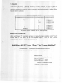
340 S/T MODIFICATION INSTRUCTIONS
IMPORTANT: Modification of exhaust system and/or engine VOIDS your WARRANTY.
Modification instructions are intended solely for race applications.
CAUTION: Modify engine, exhaust system and carlt>uretion EXACTLY as instructed,
following. ANY DEVIATION from SPECIFIED DIMIENSIONS or MODIFICATION of
PARTS NOT MENTIONED WILL DECREASE PERFORMANCE and could result in severe
engine damage.
Modifying 340 S/T from "Stock" to "Modified-Stock"
CYLINDER
A. Exhaust Port
Enlarge exhaust port of cylinder as follows:
1. Raise top edge of exhaust port to a point 1.120" (28.45mm) below top surface of cylinder.
(Figure 1) DO NOT change bottom edge of exhaust port:.
2. Increase the chordal width of exhaust port to 1.460" {3:7.08mm). (Figure 1)
NOTE: Chordal width (Figure 1) is straight line distance between side edges of port (not
following curvature of cylinder wall).
3. Enlarge radius of 4 exhaust port corners to.Q...2Q: (5.1mm). {Figure 1)
4. After grinding exhaust port, chamfer all sharp edges.
Raise Exhaust Port to 1.120"
below Top Surface of Cylinder
Lower llnlet Port to 3.675"
below To1p Surface of Cylinder
Enlarge Radius of 4 Exhaust
Port
C«(-~·:·r--0·]
.
;
I
'
..1
!
EX
IN
Enlarge Radius of 2
Bottom Inlet Port
Corners to~"
Increase Chordal Width of
Exhaust Port to 1.460"
IN
-------- Shape of "Stock" Ports
Shape of Modified Ports
Figure 1. 340 S/T "Modified-Stock" and "Super-Mo1dified" Cylinder Dimensions
B. Inlet Port
Enlarge inlet port of cylinder as follows:
1. Lower bottom edge of inlet port to a point 3.675" (93.35mm) below top surface of cylinder.
(Figure 1) DO NOT change top edge or chordal width of iniHt port.
2. Enlarge radius of 2 bottom inlet port corners to 0.25" (6.35mm). (Figure 1)
3. After grinding inlet port, chamfer all sharp edges.
EXHAUST SYSTEM
Modification of "stock" exhaust system is not permitted for "modified-stock" competition.
CARBURETION
Adjust high speed mixtures (adjust mixture needles and/or replace fixed high speed jets) to attain
"normal" coloration of spark plugs.
CAUTION: When in doubt about high speed mixture adjustment, ALWAYS select a
"richer" setting. Carburetors, which are adjusted too "loan", will cause severe internal
engine damage.
DRIVE SYSTEM
A. Maximum Engine RPM
A "modified-stock" 340 SIT will deliver maximum power when operated at 8,750 to 9,000 RPM.
Modify and adjust torque converter to increase full throttle engine RPM to this speed.
B. Drive Sheave (Clutch)
Install Drive Sheave Modification Kit (D-71711A 1 ). Modify profile of drive sheave ramps to attain
correct full throttle engine RPM (as recommended in preceding !Paragraph) and desired shift pattern.
NOTE: Clutch modification instructions are supplied with modification kit.
C. Sprockets
Snowmobile may require "re-gearing" because of increase1d horsepower (a result of engine
modification). Installation of another driver sprocket may be desired (depending upon operating
conditions) to change top speed of snowmobile (MPH) and accetleration. (Refer to "Driver Sprocket
Chart", following.)
DRIVER SPROCKET CHAFtT
Top Speed of Snowmobile (MPH)
No. of Tee1th
Part Number
High MPH
17
16
15
D-63573
D-64131
D-63318A1
D-64684
D-68439
D-69757-12
14•
Low MPH
13
12
• Standard (factory installed) 340 SIT driver sprocket
Modifying 340 S/T from "Stock" to "Super-Modified"
ENGINE
A. Cylinder
1. Exhaust Port - Enlarge cylinder exhaust port as outlined in "Modifying 340 SIT from 'Stock'
to 'Modified-Stock'~ preceding.
2. Inlet Port - Enlarge cylinder inlet port as outlined in "Modifying 340 SIT from 'Stock' to
'Modified-Stock''~ preceding.
B. Ignition Timing
Retard ignition timing {full advance) from 0.100" BTDC to 0.080" BTDC {2.54mm to 2.03mm).
EXHAUST SYSTEM
A. Exhaust Pipe Center Section
1. Cut~ {11.43cm) from center section of each exhaust pipe. {Figure 2)
2. Before re-welding exhaust pipes, position pipes in snowmobile and rotate sections to attain best
fit.
3. Weld sections of exhaust pipes together. Be sure that welds are smooth and do not restrict
exhaust.
B. Exhaust Pipe Stinger
1. Cut production stinger from each exhaust pipe.
NOTE: Converging cone of exhaust pipes may have to be cut back slightly, so that inside
diameter (!D) of cones are enlarged to J::. (25.4mm) (same ID as replacement stinger).
2. Weld modified stingers [1" ID x 0.040" thick {approximately) x 10.5" long {25.4mm x
1.02mm x 26.67cm) - Figure 2] to converging cones. Be sure that welds are smooth and do not
restrict exhaust.
Left
Pipe
~------\
L...£C_
/_
eon,..g;ng Cones
(Rotate fo• Ben
'\, ~\0)
:.-:-Sections)
Modified
Stingers
-------.....J
Figure 2. 340 SIT "Super-Modified" Exhaust Pipes
CARBURETION
Adjust high speed mixtures (adjust mixture needles and/or replace fixed high speed jets) to achieve
"normal" coloration of spark plugs.
CAUTION: When in doubt about high speed mixture adjustment, ALWAYS select a
"richer" setting. Carburetors, which are adjusted too "lean", will cause severe internal
engine damage.
DRIVE SYSTEM
A. Maximum Engine RPM
A "super-modified" 340 S!T will deliver maximum power when operated at 9,750 to 10,000 RPM.
Modify and adjust torque converter to increase full throttle engine RPM to this speed.
B. Drive Sheave (Clutch)
Install Drive Sheave Modification Kit (D-71711A 1 ). Modify profile of drive sheave ramps to attain
correct full throttle engine RPM (as recommended in preceding paragraph) and desired shift pattern.
NOTE: Clutch modification instructions are supplied with modification kit.
C. Sprockets
Snowmobile may require "re-gearing" because of increased horsepower (a result of engine and
exhaust modification). Installation of another driver sprocket may be desired (depending upon
operating conditions) to change top speed of snowmobile (MPH) and acceleration. (Refer to "Driver
Sprocket Chart", preceding.)
Sno-Twister/Hi-Performa ce Tipster
NOTICE: Sno-Twister/Hi-Perlormance "Tipsters" aro in numerical
order, starting with 75-1. If the first copy you recei~'e is (example)
75-3 -- and you desire previous " Tipster" issues (75-1 and 75-2) advise Mercury Marine Publications Dept., P.O. Box 11108, Fond du
Lac, WI 54935. and give the first number that you received.
NO. 75-7 {11 122174}
440 S/T MODIFICATION I"ISTRUCTIONS
IMPORTANT: Modification of exhaust system and/or engine VOIDS your WARRANTY.
Modification instructions are intended solely for race applications.
CAUTION: Modify engine, exhaust system and carburetion EXACTLY as instructed,
following. ANY DEVIATION from SPECIFIED DIMENSIONS or MODIFICATION of
PARTS NOT MENTIONED WILL DECREASE PEFUFORMANCE and could result in
severe engine damage.
Modifying 440 S/T from "Stock" to "Modified-Stock"
ENGINE
A. Cylinder
1. Exhaust Port- Enlarge cylinder exhaust port as follows:
a. Raise top edge of exhaust port to a point 1.120" (28.45mm) below top surface of cylinder.
(Figure 1) DO NOT change bottom edge of exhaust !POrt.
b. Increase chordal width of exhaust port to 1.690" (42.93mm). (Figure 1)
NOTE: Chordal width (Figure 1) is straight line distance between side edges of port (not
following curvature of cylinder wall).
c. Enlarge radius of 4 exhaust port corners to 0.20" (5 ..08mm). (Figure 1)
d. After grinding exhaust port, chamfer all sharp edges.
Raise Exhaust Port
to 1.120" below Top
Surface of Cylinder
Enlarge Radius
of2 Top
Inlet Port
Corners to
Lower Inlet Port to 3.850" below
Top Surface t[)f Cylinder
~---- Raise Inlet Port to 2.470" below
~~~IJmt~lr1r~f£~~, Top Surf~eofCylinder
0.20"~---"'"7
EX
Enlarge Radius of 4 Exhaust
Port Comers to 0.20"
IN
Enlarge Radius of
2 Bottom Inlet Port
Increase Chordal Width of
Inlet Port t1o 1.no"
Increase Chordal Width of
Exhaust Port to 1.690"
- - - - - - - Shape of "Stock" Ports
- - - - Shape of Modified Ports
Figure 1. 440 SIT "Modified-Stock" and "Super-Modified" Cylinder Dimensions
Page 2
Snowmobile "Tipster" No. 75·7
2. Inlet Port- Enlarge cylinder inlet port as follows:
a. Lower bottom edge of inlet port to a point 3.850" (97.79mm) below top surface of
cylinder. (Figure 1)
b. Raise top edge of inlet port to a point 2.470" (62.74mm) below top surface of cylinder.
(Figure 1)
c. Increase chordal width of inlet port to 1.770" (44.96mm). (Figure 1)
d. Enlarge radius of 2 bottom inlet port
corners to 0.75" (19.05mm). (Figure 1)
e. Enlarge radius of 2 top inlet port corners
to 0.20" (5.08mm). (Figure 1)
f. After grinding inlet port, chamfer all
Remove 0.080"
sharp edges.
IN
from Inlet Side
of Piston Skirt
B. Piston
Remove 0.080" (2.03mm) from inlet side of
piston skirt. (Figure 2) After cutting piston skirt,
remove all sharp edges from skirt.
NOTE: Inlet side of piston is side opposite
exhaust mark on piston dome.
+
-- - -·-- Shape of "Stock" Piston
- - - Shape of Modified Piston
f
Figure 2. 440 SIT "Modified-stock" and
"Super-Modified" Piston
EXHAUST SYSTEM
Modification of "stock" exhaust system is not permitted for "modified-stock" competition.
CARBURETION
Adjust high speed mixtures (adjust mixture needles and/or rep,lace fixed high speed jets) to obtain
"normal" coloration of spark plugs.
CAUTION: When in doubt about high speed mixture adjustment, ALWAYS select a
"richer" setting. Carburetors, which are adjusted too "lean", will cause severe internal
engine damage.
DRIVE SYSTEM
A. Maximum Engine RPM
A "modified-stock" 440 SIT will deliver maximum power whe!n operated at 8,500 to 8,750 RPM.
Modify and adjust torque converter to increase full throttle en1gine RPM to this speed.
B. Drive Sheave (Clutch)
Install Drive Sheave Modification Kit (D-71711A 1 ). Modify profile of drive sheave ramps to attain
correct full throttle engine RPM (as recommended in preceding paragraph) and desired shift pattern.
NOTE: Clutch modification instructions are supplied with modification kit.
C. Sprockets
Snowmobile may require "re-gearing" because of increased horsepower {a result of engine
modification). Installation of another driver sprocket may be desired (depending upon operating
conditions) to change top speed of snowmobile (MPH) and acceleration. {Refer to "Driver Sprocket
Chart", following.)
Page 3
Snowmobile "Tipster" No. 75·7
DRIVER SPROCKET CHART
Number of
Top Speed of Snowmobile (MPH)
Teeth
High MPH
17
Low MPH
16
15.
14
13
12
Part Number
D-63573
D-64131
D-63318A1
D-64684
D-68439
D-69757-12
• Standard (factory installed) 440 SIT driver sprocket
Modifying 440 S/T from "Stock" to "Super-Modified"
ENGINE
A. Cylinder
1. Exhaust Port -Enlarge cylinder exhaust port {Figure 1) as outlined in "Modifying 440 SIT from
'Stock' to 'Modified-Stock' ", preceding.
2. Inlet Port - Enlarge cylinder inlet port (Figure 1) as outlined in "Modifying 440 SIT from
'Stock' to 'Modified-Stock' ", preceding.
B. Piston
Modify piston {Figure 2) as outlined in "Modifying 440
preceding.
SIT from
'Stock' to 'Modified-Stock' ",
CcttEae~r
Header PiPe
fo.l:Q:,
"Squish" Area
Re-Cut "Squish"
Area out to
~, (Original
Diameter)
Figure 3. 440
SIT
----- Shape of "Stock"
Cylinder Head
___ Shape of Modified
Cylinder Head
"Super-Modified" Cylinder Head
J
Figure 4.
440 SIT "SuperModified" Exhaust
Header Pipe
C. Cylinder Head
1. Machine 0.065" {1.65mm) from face of cylinder head. {Figure 3)
2. Re-cut cylinder head "squish" area at 20° and out to original diameter [2.657" {64.49mm)].
{Figure 3)
3. Remove all sharp edges from edge of "squish" area. {Figure 3)
4. Volume of modified cylinder head {measured on flat plate) should be 23.8cc.
D. Ignition Timing
Retard ignition timing (full advance) from 0.100" (2.54mm) BTDC to 0.080" {2.03mm) BTDC.
Page 4
Snowmobile "Tipster" No. 75·7
EXHAUST SYSTEM
A. Exhaust Header Pipe
Cut each header pipe down to 2.0" (50.8mm) including flange. (Figure 4)
NOTE: Re-weld spring attaching washers to flange of header pipes.
B. Exhaust Pipe Center Section
1. Cut 1.0" (25.4mm) from center section of each exhaust pipe. (Figure 5)
2. Before re-welding exhaust pipes, position pipes in snowmobile and rotate sections to obtain best
fit.
NOTE: Spring hooks will require repositioning on exhaust pipes to give sufficient spring
tension. Left exhaust pipe (PTO side) must be heated and CAREFULLY bent to fit around
engine rewind housing. Bend left exhaust pipe in area of first bend (just after header pipe Figure 5).
3. Weld sections of exhaust pipes together. Be sure that welds are smooth and do not restrict
exhaust.
Bend Left Exhaust
Pipe in This Area
(Bend as Required to
Fit around Engine)
~-----\
LV\-~·
/_
-...\
eon ...,..•• Cones
\D
(Rotate for Best
Fit in Snowmobile--------_,...
and Re-Weld at
Center Sections)
CUt Converging Cones Back Approximately Y.z" and Weld
(ID of Cones MUST Be Same as ID of Stingers)
Figure 5. 440 SIT "Super-Modified" Exhaust Pipes
C. Exhaust Pipe Stingers
1. Cut production stinger from each exhaust pipe.
2. Cut approximately W' (12.7mm) from end of each converging cone so that inside diameter (I D)
of cones is enlarged to 1-1/8" (28.58mm) (same ID as replacement stinger). (Figure 5)
3. Weld modified stingers [1-1/8" ID x 0.040" thick (approximately) x 15" long (28.58mm x
1.02mm x 38.1cm) - Figure 5] to converging cones. Be sure that welds are smooth and do not
restrict exhaust.
Page 5
Snowmobile "Tipster" No. 75·7
CARBURETION
A. Carburetors
Replace "stock" carburetors (Mikuni VM 36) with Mikuni VM 38 carburetors (38mm). Carburetors
are available thru Mercury Marine (see "Ordering Information", following).
B. High Speed Mixture
1. Fixed high speed jets in the range of No. 400 to No. 480 (depending upon conditions of
operation) will be required in VM 38 carburetors. Fixed high speed jets are available thru
Mercury Marine (see "Ordering Information", following).
2. Adjust high speed mixtures (adjust mixture needles and/or replace fixed high speed jets) to
attain "normal" coloration of spark plugs.
CAUTION: When in doubt about high speed mixture adjustment, ALWAYS select a
"richer" setting. Carburetors, which are adjusted too "lean", will cause severe internal
engine damage.
C. Ordering Information
To obtain ordering information on modified carburetors (Mikuni VM 38) and fixed high speed jets
(No. 400 to No. 480), contact:
Mercury Marine
Hi-Performance Products Department
20 Wisconsin Street
Oshkosh, Wisconsin 54901
Attention: Snowmobile Division
Telephone: (414) 231-9180
DRIVE SYSTEM
A. Maximum Engine RPM
A "super-modified" 440 SIT will deliver maximum power when operated at 9,500 to 9,750 RPM.
Modify and adjust torque converter to increase full throttle engine RPM to this speed.
B. Drive Sheave (Clutch)
Install Drive Sheave Modification Kit (D-71711 A 1). Modify profile of drive sheave ramps to obtain
correct full throttle engine RPM (as recommended in preceding paragraph) and desired shift pattern.
NOTE: Clutch modification instructions are supplied with modification kit.
C. Sprockets
Snowmobile may require "re-gearing" because of increased horsepower (a result of engine and
exhaust modification). Installation of another driver sprocket may be desired (depending upon
operating conditions) to change top speed of snowmobile (MPH) and acceleration. (Refer to "Driver
Sprocket Chart", preceding.)
)
•
)
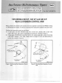
Sno-Twister /Hi-Performance Tipster
NOTICE: Sno-Twister/Hi-Performance "Tipsters" a.re in numerical
order, starting with 75-1. If the first copy you receive is (example)
75-3 -- and you desire previous "Tipster" issues (75-1 and 75-2) advise Mercury Marine Publications Dept., P .0. Box 1108, Fond du
Lac. WI 54935, and give the first number that you received.
N 0. 75-8 (J2I 6I 74}/
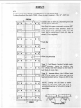
TRACK "STUD" INSTALLATION
1975 Models 340 S/T, 440 S/T and 440 T /T
(Chassis Serial No. 4205000 and Above)
On some snowmobiles, wear strips (D-70727) in the chassis tunnel will require repositioning if
installation of track studs is de:;lrcd. Make certain that the FRONT END of both wear strips extend
4" (10.16cm) forward of FRONT wear strip attaching hole in chassis. Failure to observe this
dimension exactly may result in damage to the chassis tunnel with track studs installed.
If wear strips are not correctly positioned, reposition as follows:
1. Remove seat cushion, fuel tank and slide suspension.
2. Drill out 14 rivets, which attach wear strips to chassis, and remove wear strips.
3. Reposition each wear strip so that the front end extends 4" forward of front wear strip
attaching hole in chassis. Using wear strip as a guide, drill 13/64" (5.16mm) holes thru chassis (7
for each wear strip).
4. Install fuel tank and seat cushion.
5. Attach wear strips with 14 rivets (C-17-71790).
6. Install slide suspension and readjust track tension and alignment.
•
'l
I
~
\
l
}
I'd!!
Sno-Twister IHi-Performance Tipster
NOTICE: Sno-Twister/Hi-Performance "Tipsters" are in numerical
order, starting with 75-1. If the first copy you receive is (example)
75-3 -- and you desire previous "Tipster" issues (75-1 and 75-2)advise Mercury Marine Publications Dept., P .0. Box 1108, Fond du
lac. WI 54935, and give the first number that you received.
N0. 75-8 {J2I6 I 74}I
TRACK ''STUD'' INSTALLATION
1975 Models 340 S/T, 440 S/T and 440 T/T
(Chassis Serial No. 4205000 and Above)
On some snowmobiles, wear strips (D-70727) in the chassis tunnel will require repos1t1oning if
installation of track studs is deslred. Make certain that the FRONT END of both wear strips extend
4" (10.16cm) forward of FRONT wear strip attaching hole in chassis. Failure to observe this
dimension exactly may result in damage to the chassis tunnel with track studs installed.
If wear strips are not correctly positioned, reposition as follows:
1. Remove seat cushion, fuel tank and slide suspension.
2. Drill out 14 rivets, which attach wear strips to chassis, and remove wear strips.
3. Reposition each wear strip so that the front end extends 4" forward of front wear strip
attaching hole in chassis. Using wear strip as a guide, drill 13/64" (5.16mm) holes thru chassis (7
for each wear strip).
4. Install fuel tank and seat cushion.
5. Attach wear strips with 14 rivets (C-17-71790).
6. Install slide suspension and readjust track tension and alignment.
"
-~I
I
)
Sno-Twister IHi-Performance Tipster
NOTICE : Sno-Twister/Hi-Performance "Tipsters" are in numerical
order, starting with 75-1. If the first copy you receive is (example)
75-3 •• a nd you desire previous "Tipster" issues (75-1 and 75-2) advise Mercury Marine Publications Dept., P.O. Box 1108, Fond du
Lac, WI 54935, and give the first number that you received.
No. 75-9 (12118/74)
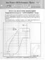
340 S/T and 440 S/T DRIVE SHEAVE RAMPS
Suggested Dimensions for ''SUPER-MODIFIED'' Ramps
As a result of factory testing, Mercury has designed a drive sheave ramp profile suitable for 340 S!T
and 440 S!T "Super-Modified" Snowmobiles (see drawing below). This ramp profile is intended to
be used with green compressio n spring and optional weights (0146-135 for 340 S!T and 0146-123
for 440 S!T).
Green compression spring, an assortment of weights, a set of "blank" ramps (hardened) and an
instruction sheet are included in Drive Sheave Modification Kit (D-71711A 1).
1.8"
Cent~~rlin
t---r--+--+--+--+--+-----+--+--t---r-
_ of Bolt_
Hole
1 7"
·
1
1
-~-+--t 1.6"
Profile of
"Blank."Jla
Profile of
"~er
I
I
Modlfied" flamp
t---r--+--+---+--+----'1 - I
-/
/
4
L
I
I
-
1.4"
.620"~------'1f---J~
I
I
-- - -T - -'
1.3"
I
I
I
r--- - : - - - - .820"-,..-----'----1----'"
I
: :I :::j
/,~r-:==-:::
.7"
/
.3"
1----+--+---1--1--.2"
(;
-+-+---1--+-- - .1"
1.4"
.5"
.4"
.3"
.2"
-r
I
_.._.___._
.1"
o
ACTUAL SIZE
Suggested Dimensions for 340 S!T and 440 SIT "Super-Modified" Drive Sheave Ramps
l
I
)
Sno-Twister IHi-Performance Tipster
NOTICE : Sno-Twister/ Hi-Performance ' 'Tipsters" for 1976 are in
numerical o rder, start ing with 7 6 -1. If t he first copy you receive is
(e xample) 7 6-3 -- and you desire previous ''Tipster" issues (76-1 and
76 -2 ) -- ad vise Mercury Marine P ublicat io ns Dept., P .0. Box 1 108,
Fond du Lac, WI 54935 and give the first nu mber that you received.
No. 76-1 (11126175)
MERCURY MARINE- CERTIFIED SNOWMOBILE SPECIFICATIONS
1976
440 TfT
1976
340 T(T
MODEL NAME
1976
440 SfT
1976
340 SfT
1976
250 SfT
ENGINE SPECIFICATIONS
Engine Manufacturer
Engine Model
No. of Cylinders
K340-2AS
2
Engine Displacement
HorsepOwer
Type of Cooling
339.3cc
40@ 7000 RPM
Axial Fan
Bore
Stroke
Ignition
Min. Compressed Head
Gasket Thickness
Min. Compressed Base
Gasket Thickness
(DVolume of Head to Top of
Spark Plug Hole - Vertical
Head Volume w/Spark
Plug -on a Flat Plate
Crankcase Volume
Overall Length of Cyl inder
Cylinder Bore Material
Depth· Topol Cylinder to
Bottom of Intake Port
Depth· Top of Cylinder to
Top of Exhaust Port
Depth- Top of Cylinder to
Top of Transfer Port(s)
Width of Transfer Ports
Width of Intake Ports
Height of Exhaust
Port/Including Chamfer
Height of Exhaust
Port/Excluding Chamfer
Width of Exhaust
Port/Top (Wide Part)
Width of Exhaust
Port/Bottom (Narrow Part
Height of Transfer Ports
Height of Intake
Port/Including Chamfer
Heoght ot Intake
Port/ Excluding Chamfer
Weight - Piston Assembly
Complete
Overall Height of Piston
(thru Center)
Height of Piston/ Exhaust SidE
Height of Piston/Intake Side
No. of A ings per Piston
Ring Type
Ring Thickness
Ring Width(s)
Crankcase Face to Center of
Crankshaft
•
Kohler
Kohler
K440·2AS
2
435.8cc
50@ 7000 RPM
Kohler
Kohler
250 RLC
2
340 RLC
2
Kohler
440 RLC
2
339.3cc
N.A.
liquid
60.0mm
60.0mm
435.8cc
N.A.
liquid
Thunderbolt CD
0.7mm
Thunderbolt CD
0.7mm
60.0mm
60.0mm
WicoCD
0.7mm
68.0mm
60.0mm
Wico CD
0.7mm
250cc
N.A.
liquid
51.5mm
60.0mm
Thunderbolt CD
0.7mm
0.3mm
0.3mm
0.2mm
0.3mm
0.3mm
12.7cc
21.7cc
10.5cc
14.2cc
16.5cc
18.5 .:t 1.0cc
26.5 .:t 1.0cc
10.7 .:t 0.8cc
17.5 .:t 0.8cc
23.5 .:t l.Occ
310.0cc
109.0 + 0.5mm
305.0cc
109.0 + O.Smm
Chrome Plated Alum.
93.9±. 1.0mm
305.0cc
Chrome Plated Alum.
92.5.!. l.Omm
310.0cc
109.0 + 0.5mm
Chrome Plated Alum.
92.5 ;t l.Omm
109.0 + 0.5mm
Chrome Plated Alum.
92.5± 1.0mm
305.0cc
109.0 + 0.5mm
Chrome Plated Alum.
9G.O.:t 1.0mm
33.0;t 1.2mm
33.0.!. 1.2mm
28.7 ± 1.2mm
29.5± 1.2mm
28.6.!. 1.2mm
47.3.!_1.2mm
47.3 .!. 1.2mm
46.5_!1.2mm
46.5± 1.2mm
46.5.!. 1.2mm
34.2+ 1.0/14.1 + 1.0mm
42.0+ 0.8mm
27.0.!. 1.2mm
33.8 + 1.0/12.8 + 1.0mm
48.0+0.8mm
27.0.!. 1.2mm
27.7.!. 1.0/1 0.7 + 1.0mm
40.0_!0.8mm
31.2_!1.2mm
32.3 + 1.0/12.5 + 1.Omm
44.0_!0.8mm
30.5.!. 1.2mm
32.1.!. 1.0/15.2 + 1.0mm
42.0+0.8mm
31.0.!. 1.2mm
26.5 .!_ 0.7mm
26.5 .!_0.7mm
30.7 .:t0.7mm
30.0.:t0.7mm
30.5_!0.7mm
42.0!. 0.5mm
42 .0.!_0.5mm
32.0!. 0.5mm
42.0.!_0.5mm
42.0.!_0.5mm
N.A.
N.A.
28.0.!_0.5mm
35.0_! 0.5mm
35.0.±_0.5mm
12.7 + l.Omm
24.5.:t0.9mm
12.7 + 1.0mm
24.5.:t0.9mm
13.5 + l.Omm
30.9_!0.9mm
13.5 + 1.0mm
30.5.:t0.9mm
13.5+ l.Omm
34.0.!_0.9mm
24.0.!_0.7mm
24.0.:t0.7mm
30.4 _!0.7mm
30.0_!0.7mm
33.5.:t0.7mm
240.2g .:t 10%
335g.:t 10%
198.0.!. 10.0g
240.0.!. lO.Og
309.0 .±. 10.0g
70.5;t0.8mm
71.7 .:t 0.8mm
68 .7 ;t0.8mm
67.15;t0.8mm
70.7 ;t0.8mm
65.0.!_ 0.8mm
63.0+ 0.8mm
65.0+ O.Smm
65.0!_0.8mm
2
"L" and Rectangular
65.0+0.8mm
63.0+0.8mm
62.0+0.8mm
60.0+0.8mm
1
"L" - Keystone
1.995mm
2.6mm
70.0.±_0.5mm
64.0+0.8mm
62.0+ O.Smm
1
"L ·Keystone
2.515mm
J.Omm
2
"L" and Rectangular
1.995mm
2.7/2.4mm
70.0!_0.5mm
Axial Fan
"L"/2.515-R ectJ1.995m n 1.995mm
3.0/2.7mm
2.12mm
70.0;t0.5mm
70.0.:t0.5mm
DBA Level
78 .t_2
78 + 2
Head Pipe Length
Head Pioe Inside Diameter
(2) 4.0" + 0.192"
(2)
, .563" + 0.025"
1
"L.. · Keystone
4.0"!. 0.192"
1.563" + 0.025"
78.±.2
1.5" !. 0.192"
1.5" + 0.02"
(3)
(j) Piston @ TDC
® Y-Pipe Manifold with Single Expansion Chamber and Muffler Assembly
®Twin Expansion Chambers Discharging into Single Muffler
(OVER)
68.0mm
60.0mm
70.0;t0.5mm
78.! 2
78.±.2
(3)
(3) 1.5" +0.192"
1.5".:!:. 0.192"
1.625' +. U.02'
1.625' +. U.02''
N.A. = Not Applicable
NOTE: See Bottom of Page 2
for Metric/U.S. Conversion
1976
340 TIT
MODEL NAME
1976
440TIT
1976
340 SIT
1976
250 SIT
1976
440 SIT
CARBURETOR
Make/Model No.
No. per Engine
Venturi · Smallest 0 iameter
in Throat
Throttle Bore· Largest Dia.
Downstream of Butterfly
Choke
Mikuni/VM32·91
2
32.0mm
Mikuni/VM36·34
2
36.0mm
Mikuni/VM34
2
34.0mm
Mikuni/VM 36
2
36.0mm
Mikuni/VM38
2
37.5mm
33.0mm
37.0mm
34.5mm
37.0mm
38.0mm
Yes
Yes
Yes
Yes
Yes
Arctic XXXX · 077
3200 RPM :!:. 200
1tBiue
Arctic XXXX · 080
3200 RPM + 200
1ttltue
.192"! .005"
2.49' !_.12'
.192" + .005"
2.49":!:. .12"
Arctic XXXX · 01:11
4000 RPM
1/Green
.192.:!:. .005"
4.375' :!:. .250'
Arctic XXXX • 088
4000 RPM
1/Green
.HI:.!' ;!:..I.Xr.)·
4.;$1~' :!:. .:t:.u•
Arctic XXXX · 089
4000 RPM
1/Green
.192' .!_.005'
4.;st~· :!:. .l~u·
3.9
2.31"!: .040"
3.9
2.31":!:. .040"
5
2.375":!:. .040"
5
2.375"! .040"
5
2.375":!:. .040"
27.8;t2.0g
.470" ;!:..010"
33.9 z2.0o
.470".!. .010"
28.34 +. :l.Ug
.470":!:. .010"
l~.;stl
.470".!. .010"
.470":!:. .010"
Arctic XXXX · 015
1
Arctic XXXX · 015
1
Arctic XXXX · 0115
1
Arctic XXXX • 015
1
Arctic XXXX · 015
1
DRIVE CLUTCH
Make/Model No.
Engagement Speed
No. of Springs/ Color
Spring Wire Diameter
Drive Clutch Spring ·
Free Length
No. of Turns
Drive Clutch Spring·
Outside Diameter
Arm/ Roller Weight
Drive Clutch · Roller
Diameter
+. :t.ug
28.34!: 2.0g
DRIVEN CLUTCH
Make/Model No.
Quantity/Driven Clutch
Spring(s)
Spring Wire Diameter
No. of Turns
Driven Clutch Spring·
Free Length
Ramp Angle
.156" + .005"
.156" + .005"
.156" + .005"
.156" + .005"
.156" ± .005"
5
5.00' :!:. .250'
5
5.()(l":!:. 250"
5
5.00":!:. .250"
5
5.00":!:. .250"
5
5.00"! .250"
30":!:. 2"
30":!:. 2"
30"! 20
J00+20
JOO+~
74001
74001
Slide Rail
99.44"! .500"
88.00" :!:. .250"
37.500" + .125"
39.500" + .250"
4.62";!:..060"
74558
Slide Rail
89.875":!:. .250"
82.875" + .250"
33.500" + .250"
39.250" + .250"
4.06":!:. .08"
35.00" + .125"
74558
Slide Rail
89.875"! .250"
82.875" + .250"
33.500" + .250"
39.250" + .250"
4.06" + .06"
35.00".!. .125"
74558
Slide Rail
89.875" + .250"
82.875" + .250"
33.500" + .250"
39.250" + .250"
4.06";t.06"
35.00" + .1 25"
CHASSIS/SUSPENSION
Chassis Model
Suspension
Overall Vehicle Length
Chassis Length
Ski Length
Overall Vehicle Width
Sk i Width
Center Distance between Skis
Slide Rail
99.44":!:. .500"
88.00 + .250"
;${.:>~)' :!:. .l;t~··
39.509"! .250"
4.62";!:. .060"
;ss.OO" + .125"
;s:..w·
;!:..ll~··
TRACK
Material
Width
Pitch Length
Track Drive Sprocket Teeth
Idler Diameter
Rubber/Steel Bars
15.00"+ .125"
110.88"
9
7.625"
Rubber/Steel Bars
15.00";!:..125"
110.88"
9
7.625"
Rubber/Grouser
15.00" + .125"
102.00"
12
7.625"
Rubber/Grouser
15.00";!:..125"
102.00"
12
7.625"
Rubber/Grouser
15.00" + .1 25"
102.00"
12
7.625"
17
18
14
15
16
34
34
34
34
34
12·13·14·15·16-18
12·13·14·15·16-17
12·13·15·16·17·UI
12·13·14·16-17·18
12·13·14·15-17·18
28·36
28·36
28·36
28-36
28·36
2
2
2
2
2
365:!:. 151bs.
365:!:. 151bs.
330+ 101bs.
330 + 10 lbs.
330 + 10 lbs.
CHAINCASE
Standard Drive Sprocket
No. of Teeth
Standard Driven Sprocket
No. of Teeth
Optional Drive Sprockets
No. of Teeth
Optional Driven Sprockets
No. of Teeth
Drive Chain/Rows
.
WEIGHT
Overall (Less Gas)
METRIC/U.S. CONVERSION: 1mm (millimeter)= 0.0394" (inch); 1" = 25.4mm; 11 g (gram)= 0.04oz.;
1cc (cubic centimeter)= 0.06 cu. in.; 1 lb. (pound) •= 0.4536kg (kilogram)
'
Sno-Twister IHi-Performance Tipster
NOTICE: Sno-Twister/Hi-Performance "Tipsters" for 1976 are in
numerical order, starting with 76-1. If the first copy you receive is
(example) 76-3 --and you desire previous "Tipster" issues (76-1 and
76-2) --advise Mercury Marine Publications Dept., P.O. Box 1108,
Fond du lac, WI 54935 and give the first number that you received.
No. 76-2 (11126175)
SET-UP INFORMATION
''Stock'' - 1976 Model 250-340-440 S/T Snowmobiles
IGNITION TIMING
Standard ignition timing for each model (as specified in the Sff "Operation and Maintenance
Manual") MUST BE ADHERED TO. Advancing ignition timing beyond the recommended
specification will gain absolutely nothing and could cause serious engine damage.
SPARK PLUGS
Standard spark plugs (Champion ON-19V) MUST BE USED FOR RACING. Champion N-55G plugs
(which are easier to "read") may be used to determine correct carburetor "jetting" ONLY.
CYLINDER HEAD - "SQUISH" CHAMBER CLEARANCE
A MINIMUM of .030" (0.76mm) clearance must be maintained between cylinder head and piston
dome [heads torqued to 225 in. lbs. (259kg-cm) after engine warmup to a minimum of 110° F
(430 C)]. When re-using head gaskets, check "squish" chamber clearance as follows:
1. Place a piece of L-shaped, soft, wire solder through the spark plug hole to the cylinder wall.
2. Rotate engine over TDC.
3. Remove and measure flattened section of wire solder.
COOLING SYSTEM
• When installing cylinder heads, a thin film of GE Silicone Sealer should be used on both sides of
the cylinder head gaskets.
• If coolant leakage should occur at cylinder head mounting studs, clean the mounting hardware
and apply GE Silicone Sealer to the stud threads and bosses on the cylinder heads.
• In extreme cold temperatures, it may be necessary to "tape off" a portion of the radiator to
maintain the recommended engine operating temperature [above 1100 F (430 C) MINIMUM).
• Frequently check and tighten all hose clamps.
CARBURETORS
440 SIT
Engine idle = 3000 RPM
Calibration = No change from standard settings
340 S/T
Engine idle = 3000 RPM
Calibration = No change from standard settings
250 S/T
Engine idle = 3000 RPM
Calibration = CHANGE jet needle E-rings from 2nd groove from top to 4th groove
from top.
TORQUE SPECIFICATIONS
Torque Specs
Cylinder block .
Crankcase halves (only) .. . . . . . .
Cylinder head . . . . . . . . . . . . . .
Rotor nut . . . . . . . . . . . . . .. .
Screws to water pump cover . . . . . . . . . . . . . .
Retractable starter . . . . . . . . . . . . . . . . . . .
Drain plug . . . . . . . . . . . . . . . . . . . . . . . .
Exhaust flange . . . . . . . . . . . . . . . . . . . . .
Spark plug . . . . . . . . . . . . . . . . . . . . . .. .
250 S/T
.
.
.
.
.
185 in. lbs.
155 in. lbs.
225 in. lbs.
90ft. lbs.
95 in. lbs.
85 in. lbs.
95 in. lbs.
85 in. lbs.
18ft. lbs.
340 S/T & 440 S/T
225 in. lbs.
155 in. lbs.
225 in. lbs.
90ft. lbs.
95 i11. lbs.
85 in. lbs.
95 in. lbs.
85 in. lbs.
18ft. lbs.
(1 in. lb.= 1.15kg-cm; 1ft. lb.= .14mkg)
THROTTLE CABLES
Occasionally lubricate throttle cable core wires with WD40 or LPS lubricant.
1. Lubricate from ends of cables around core wires, and/or
2. Drill a 1 /16" (1.6mm) hole in top end of cable junction block and lubricate through the hole.
CLUTCHING
To obtain and maintain ultimate snowmobile performance, proper clutch operation is a "must" in
maintaining peak engine operating RPM.
1. Use drive belt D-57-74294 (identified by white patch on belt cover).
2. 250 SIT - adjust driven sheave spring preload to achieve 9200 to 9500 engine RPM at W.O.T.
acceleration.
3. 340 SIT - 440 SIT - adjust driven sheave spring preload to achieve 9250 to 9500 engine RPM at
W.O.T. acceleration.
4. Frequently disassemble, clean and inspect drive clutch assembly - once every race day is
recommended.
IMPORTANT: To prevent scarring or chipping the inside diameter of the cover bushing, TAKE
PARTICULAR CARE to keep cover "SQUARE" on shaft (prevent cocking and binding), as
cover is removed and/or installed. This task is made somewhat easier if the complete drive
clutch is removed from the engine before disassembly.
During each inspection, be certain to inspect the bushings in all of the roller assemblies. Failure to
recognize and replace roller assemblies with worn bushings will lead to premature ramp destruction.
NOTE: Construction and use of the simple tool (sketched below) is an unbelievable time-saver
(not to mention an aid to your sanity) when removing and installing the roller assemblies.
Round the Edges
1" (25.4mm) Approx.
''A''
3/8" (9.5mm)
~1'--.-570-"~J
.580"
G::~::)
I~
SCALE -1:1
Insert Tang ''A"
between Roller Arm
and Twist Tool
to Spread Arms.
Material:
3/16" (4.8mm)
Thick Steel
SKI ASSEMBLIES
c
1. Check both leaf springs to make certain that they move freely in the plastic slides. If necessary,
grind or file the sides of the spring, as required.
2. Check the "curl" of the leaf spring (top forward end) to make sure that the "curl" does not hit
the shock absorber when the spring is collapsed. If necessary, grind or file end of spring "curl",
as required.
CARBIDE SKEGS
Starting with Standard Carbide Skegs D-74783-1 (ten, 1" carbide segments; numbered 1-thru-10,
front to rear) 1. Move carbide segment Nos. 1 and No. 2 behind No. 3. Move No. 4 carbide segment behind No.
10.
2. Depending upon conditions and individual preference, you also may want to add two more 1"
carbide segments; one behind No. 3 and one behind No. 10 [4" and 8" (10cm and 20cm)
carbide skeg] .
SUSPENSION ADJUSlMENTS
Initial suspension settings should be:
1. Front arm in upper chassis hole and middle hole on the suspension.
2. Set the springs quite stiff.
Weight transfer effect can be increased by increasing the angle of the front arm (lower hole in the
suspension).
Weight transfer effect can be decreased by decreasing the angle of the front arm (lower hole in
chassis or upper hole in suspension).
NOTE: Less weight transfer effect results in more ski pressure while accelerating.
TRACK "STUDDING"
Handling on hard ice appears best when track is studded generously with carbide studs on the outer
track bands and scat studs (or "claws") scattered across the center track band.
1
1,
~
hl
,__),
I
Sno-Twister IHi-Performance Tipster
NOTICE: Sno-Twister/Hi-Performance "Tipsters" for 1976 are in
numerical order, starting with 76·1. If the first copy you receive is
(example) 76-3 ··and you desire previous "Tipster" issues (76-1 and
76-2) •· advise Mercury Marine Publications Dept., P.O. Box 1108,
Fond du lac, WI 54935 and give the first number that you received.
No. 76-3 (R1-1211175)
250 S/T MODIFICATION INSTRUCTIONS
IMPORTANT: Modification of exhaust system and/or engine VOIDS your WARRANTY.
Modification instructions are intended solely for race applications.
CAUTION: Modify engine, exhaust system and carburetion EXACTLY as instructed,
following. ANY DEVIATION from SPECIFIED DIMENSIONS or MODIFICATION of
PARTS NOT MENTIONED WILL DECREASE PERFORMANCE and could result in severe
engine damage.
Modifying 250 S/T from "Stock" to "Modified-Stock"
and "Super-Modified"
ENGINE
A. Cylinders
1. Exhaust Port- Enlarge exhaust port of each cylinder as follows:
a. Raise top edge of exhaust port to a point 1.100" (27.94mm) below top surface of cylinder.
(Figure 1) DO NOT change bottom edge of exhaust port.
b. Square off side edges of exhaust port (down to a point directly opposite top of transfer
ports) while increasing chordal width of port to 1.438" (36.00mm). (Figure 1) Cut a 0.50"
(12.70mm) radius in side edges of exhaust port (at a point directly opposite top of transfer
ports) and continue side edges of port over to bottom edge of port, as shown in Figure 1.
NOTE: Chordal width (Figure 1) is straight line distance between side edges of port (not
following curvature of cylinder wall).
c. Change radius of 2 top exhaust port corners to 0.20" (5.08mm). (Figure 1)
d. After grinding exhaust port, make a 0.060" ( 1.52mm) chamfer to top edge of exhaust port.
(Figure 1) DO NOT chamfer side edges or bottom edge of port.
e. Remove sharp edges from exhaust port by lightly rounding cylinder bore edges of port with
fine emery cloth.
Raise Exhaust Port to 1.100"
below Top Surface of Cylinder
Lower Inlet Port to 3.779"
below Top Surface of Cylinder
j
Reduce Boss to Minimum
Required to Completely
Cover Piston Ring When
Piston Is at BDC
(Bottom Dead Center)
Cut 41nlet
Port Corners
at a Radius
of 0.20"
I(
1-,
Change Radius of
Make a 0.060"
2 Top Exhaust Port
Chamfer to Top
Edge of Exhaust
Port
f ....-::~-~-,<
t
~~~~--------~
I
1This Point on Side E X
Edges of Exhaust
'--.-.:-....-:-~ Port Must Be
Cut a ~ Radius in
IN
,---+----..
Directly Opposite
Side Edges of Exhaust
Make a 0.060" Chamfer
Top of Transfer
Port (at a Point Directly
Ports
Opposite Top of Transfer
Ports) and Continue
Square Off Side Edges of Exhaust------.
Side Edges of Port
Port (Down to a Point Directly Opposite
over to Bottom Edge
Top of Transfer Ports) While
Increasing Chordal Width to
~
EX
IN
····------····Shape of "Stock" Ports
--------Shape of Modified Ports
Figure 1. 250 SIT ..Modified-Stock" Cylinder Dimensions
2.
Inlet Port- Enlarge inlet port of each cylinder as follows:
a.
Lower bottom edge of inlet port to a point 3.779" (95.99mm) below top surface of
cylinder. (Figure 1) DO NOT change top edge or chordal width of inlet port.
b. Cut 4 inlet port corners at a radius of 0.20" (5.08mm). (Figure 1)
c. Reduce boss at top edge of inlet port to a minimum. (Figure 1) Boss must be large enough
to completely cover piston ring when piston is at BDC (bottom dead center).
d. After grinding inlet port, make a 0.060" (1 .52mm) chamfer to bottom edge of inlet port.
(Figure 1) DO NOT chamfer side edges or top edge of port.
e. Remove sharp edges from inlet port by lightly rounding cylinder bore edges of port with
fine emery cloth.
IMPORTANT: DO NOT POLISH transfer passages.
B. Ignition Timing
Retard ignition timing to 16.00 BTDC@ 3000 RPM
IMPORTANT: Ignition timing will retard slightly as engine RPM increases (a normal
characteristic of this ignition system). For this reason, the timing specification of 160 is
applicable ONLY at 3000 RPM and is equivalent to 130 BTDC@ 9250 RPM.
EXHAUST SYSTEM
NOTE: When removing parts (muffler, air intake box, etc) from snowmobile, keep in mind that
you are making the machine lighter. A certain amount of weight may have to be retained to
meet weight limit.
~_)
Replace "stock" exhaust system with modified exhaust pipes (available thru Mercury Marine). To
obtain ordering information on modified pipes, contact:
Mercury Marine
Hi-Performance Products Department
20 Wisconsin Street
Oshkosh, Wisconsin 54901
Attention: Snowmobile Division
Telephone: (414) 231-9180
CARBURETION
1. Remove carburetor air intake box from snowmobile.
2. Remove large air funnel from each carburetor.
NOTE: When removing parts (muffler, air intake box, etc) from snowmobile, keep in mind that
you are making the machine lighter. A certain amount of weight may have to be retained to
meet minimum weight limit.
3. Check synchronization of carburetor throttle valves and readjust as necessary.
CAUTION: When in doubt about a carburetor adjustment, ALWAYS select a "richer"
setting. Carburetors, which are adjusted too "lean", will cause severe internal engine
damage.
4. Check carburetor adjustments (idle speed, low speed mixture, jet needles and fixed high speed
jets). Adjust high speed mixture (replace fixed high speed jets) to achieve "normal" coloration
of spark plugs.
NOTE: Use fixed high speed jets which are 1 to 2 jet sizes larger (richer) than those required for
a "stock" 250 SIT.
DRIVE SYSTEM
A. Maximum Engine RPM
A "modified-stock" and "super-modified" 250 SIT will deliver maximum power when operated at
9,900 RPM ("running on" to 10,200 RPM). Modify and adjust torque converter to increase full
throttle engine RPM to this speed.
B. Drive Sheave (Clutch)
Install Drive Sheave Modification Kit (D-71711A2). Modify profile of drive sheave ramps to obtain
correct full throttle engine RPM (as recommended in preceding paragraph) and desired shift pattern.
NOTE: Clutch modification instructions are supplied with modification kit.
r
C. Sprockets
Snowmobile may require
"re-gearing" because of increased horsepower (a result of engine and
exhaust modification). Installation of another driver sprocket may be desired (depending upon
operating conditions) to change top speed of snowmobile (MPH) and acceleration. (Refer to "Driver
Sprocket Chart", following.)
DRIVER SPROCKET CHART
Top Speed of Snowmobile {MPH)
No. of Teeth
High MPH
18
Low MPH
17
16
15
14.
13
12
Part Number
D-69757A18
D-69757A17
D-69757A16
D-69757A 15
D-69757A 14 •
D-69757A 13
D-69757A12
• Standard (factory installed) 250 SIT driver sprocket
BREAK-IN PROCEDURE
After modifying an S!T Snowmobile and prior to racing, the engine should be "run in" at part
throttle (50% to 75% power) for one hour. Operate engine at 11QOF to 1700F (coolant
temperature) for "Break-In" and all operation thereafter.
Sno-Twister IHi-Performance Tipster
NOTICE: Sno-Twister/Hi-Performance ''Tipsters" for 1976 are in
numerical order, starting with 76·1. If the first copy you receive is
(example} 76-3- and you desire previous ''Tipster" issues (76-1 and
76-2} -- advise Mercury Marine Publications Dept., P.O. Box 1108,
Fond du lac, WI 54935 and give the first number that you received.
No. 76-4 (1211175)
340 S/T MODIFICATION INSTRUCTIONS
IMPORTANT: Modification of exhaust system and/or engine VOIDS your WARRANTY.
Modification instructions are intended solely for race applications.
CAUTION: Modify engine, exhaust system and carburetion EXACTLY as instructed,
following. ANY DEVIATION from SPECIFIED DIMENSIONS or MODIFICATION of
PARTS NOT MENTIONED WILL DECREASE PERFORMANCE and could result in severe
engine damage.
Modifying 340 S/T from "Stock" to "Modified-Stock"
CYLINDERS
A. Exhaust Port
c
Enlarge exhaust port of each cylinder as follows:
1. Raise top edge of exhaust port to a point 1.100" (27.94mm) below top surface of cylinder.
. (Figure 1) DO NOT change bottom edge of exhaust port.
2. Square off side edges of exhaust port while maintaining a chordal width of ~~~ (42.00mm).
(Figure 1)
NOTE: Chordal width (Figure 1) is straight line distance between side edges of port (not
following curvature of cylinder wall).
3. Change radius of 2 top exhaust port corners to 0.20" (5.08mm). (Figure 1)
4. Enlarge radius of 2 bottom exhaust port corners to 0.50" (12.70mm). (Figure 1)
5. After grinding exhaust port, make a 0.060" (1.52mm) chamfer to top and bottom edges of
exhaust port. (Figure 1) DO NOT chamfer side edges of exhaust port.
6. Remove sharp edges from exhaust port by lightly rounding cylinder bore edges of port with fine
emery cloth.
c
Raise Exhaust Port
to 1.100" below Top
Lower Inlet Port to
Top
Surface of Cylinder
~"below
Reduce Boss to Minimum
Required to Completely
Cover Piston Ring When
Piston Is at BDC
(Bottom Dead Center)
Make a Q..QRQ" E
Chamfer to Bottom
Edge of Exhaust
Port
IN
Change Radius of 2
Top Exhaust Port
Corners to 0.20"
Make a~"
Chamfer to Top
Bottom Edge of Inlet Port
x
\
Enlarge Radius of 2 Bottom
Exhaust Port Corners to 0.50"
EX
Square Off Side Edges of Exhaust Port _ ___J_...__,.__
White Keeping a Chordal Width of 1.654"'
-------Shape of "Stock" Ports
----Shape of Modified Ports
Figure 1. 340 SIT ,.Modified-Stock" Cylinder Dimensions
B. Inlet Port
Enlarge inlet port of each cylinder as follows:
1. Lower bottom edge of inlet port to a point 3.779" (95.99mm) below top surface of cylinder_
(Figure 1) DO NOT change top edge or chordal width of inlet port.
2. Cut 2 bottom inlet port corners at a radius of 0.20" (5.08mm). (Figure 1)
3. Reduce boss at top edge of inlet port to a minimum. (Figure 1) Boss must be large enough to
completely cover piston ring when piston is at BDC (bottom dead center).
4. After grinding inlet port, make a 0.060" (1.52mm) chamfer to bottom edge of inlet port.
(Figure 1) DO NOT chamfer side edges or top edge of inlet port.
5. Remove sharp edges from inlet port by lightly rounding cylinder bore edges of port with fine
emery cloth.
IMPORTANT: DO NOT POLISH transfer passages.
EXHAUST SYSTEM
NOTE: When removing parts (muffler, air intake box, etc) from snowmobile, keep in mind that
you are making the machine lighter. A certain amount of weight may have to be retained to
meet minimum weight limit.
Remove muffler assembly from snowmobile and modify "stock" exhaust system as follows:
A. Exhaust Pipe Diverging Cones
1. Cut 0.75" (19.05mm) from diverging cone of each exhaust pipe directly behind header joint.
(Figure 2)
2. Weld header joint to diverging cone of each exhaust pipe. Be sure that welds are smooth and do
not restrict exhaust.
3. Reposition spring hooks on exhaust pipes to give sufficient spring tension.
_)
c
Cut 0.75" from Diverging Cone
of Each Exhaust Pipe (Directly
Behind Heeder Joint) and Re-weld
~~
1.00"1D
Converging Cones
(Rotate for Best
Fit in Snowmobile
and Re-weld Center
Sections)
Modified--------+Stingers
Weld
Figure 2. 340 S(f "Modified-Stock" Exhaust Pipes
c
B. Exhaust Pipe Center Sections
1. Cut 0.50" (12.70mm) from center section (at widest part) of each exhaust pipe. (Figure 2)
2. Before re-welding exhaust pipes, position pipes in snowmobile and rotate sections to obtain best
fit.
3. Weld sections of exhaust pipes together. Be sure that welds are smooth and do not restrict
exhaust.
C. Exhaust Pipe Stingers
1. Cut production stinger from each exhaust pipe.
NOTE: Converging cone of exhaust pipes may have to be cut back slightly so that inside
diameter (ID) of cones is enlarged to 1.00" (25.40mm) (same ID as replacement stinger).
2. Weld modified stingers [1.00" ID x 0.040" thick (approximately) x 17 .00" long (25.40mm x
1.02mm x 43.18cm) - Figure 2] to converging cones. Be sure that welds are smooth and do not
restrict exhaust.
CARBURETION
1. Remove carburetor air intake box from snowmobile.
2. Remove large air funnel from each carburetor.
c
NOTE: When removing parts (muffler, air intake box, etc) from snowmobile, keep in mind that
you are making the machine lighter. A certain amount of weight may have to be retained to
meet minimum weight limit.
3. Check synchronization of carburetor throttle valves and readjust as necessary.
CAUTION: When in doubt about a carburetor adjustment, ALWAYS select a "richer"
setting. Carburetors, which are adjusted too "lean", will cause severe internal engine
damage.
4. Check carburetor adjustments (idle speed, low speed mixture, jet needles and fixed high speed
jets). Adjust high speed mixture (replace fixed high speed jets) to achieve "normal" coloration
of spark plugs.
NOTE: Use fixed high speed jets which are 3 to 4 jet sizes larger (richer) than those required for
a "stock" 340 SIT.
DRIVE SYSTEM
A. Maximum Engine RPM
A "modified-stock" 340 SIT will deliver maximum power when operated at 9.750 RPM ("running
on" to 10,000 RPM). Modify and adjust torque converter to increase full throttle engine RPM to
this speed.
B. Drive Sheave (Clutch)
Install Drive Sheave Modification Kit (D-71711A2). Modify profile of drive sheave ramps to obtain
correct full throttle engine RPM (as recommended in preceding paragraph) and desired shift pattern.
NOTE: Clutch modification instructions are supplied with modification kit.
C. Sprockets
Snowmobile may require "re-gearing" because of increased horsepower (a result of engine and
exhaust modifications). Installation of another driver sprocket may be desired (depending upon
operating conditions) to change top speed of snowmobile (MPH) and acceleration. (Refer to "Driver
Sprocket Chart", following.)
DRIVER SPROCKET CHART
Too Soeed of Snowmobile (MPH)
High MPH
~
,
Low MPH
No. of Teeth
18
17
16
15•
14
13
12
Part Number
D-69757A18
D-69757A17
D-69757A16
D-69757 A 15 •
D-69757A14
D-69757A13
D-69757A 12
• Standard (factory installed) 340 SIT driver sprocket
BREAK-IN PROCEDURE
After modifying an SIT Snowmobile and prior to racing, the engine should be "run in" at part
throttle (50% to 75% power) for one hour. Operate engine at 11QOF to 17QOF (coolant
temperature) for "Break-In" and all operation thereafter.
Modifying 340 S/T from "Stock" to "Super-Modified"
A limited number of "Super-Mod Kits" are available thru Mercury
Marine. To obtain ordering information on these kits, contact:
Mercury Marine • Hi-Performance Products Department • 20 Wisconsin Street • Oshkosh,
Wisconsin 54901 • Attention: Snowmobile Division • Telephone: (414) 231-9180
J
Sno-Twister IHi-Performance Tipster
NOTICE: Sno-Twister/Hi-Performance "Tipsters" for 1976 are in
numerical order, starting with 76-1. If the first copy you receive is
(example) 76-3 ··and you desire previous "Tipster" issues (76-1 and
76-2) •• advise Mercury Marine Publications Dept., P.O. Box 1108,
Fond du Lac, WI 54935 and give the first number that you received.
No. 76-5 (12/l/75)
440 S/T MODIFICATION INSTRUCTIONS
IMPORTANT: Modification of exhaust system and/or engine VOIDS your WARRANTY.
Modification instructions are intended solely for race applications.
CAUTION: Modify engine, exhaust system and carburetion EXACTLY as instructed,
following. ANY DEVIATION from SPECIFIED DIMENSIONS or MODIFICATION of
PARTS NOT MENTIONED WILL DECREASE PERFORMANCE and could result in severe
engine damage.
Modifying 440 S/T from "Stock" to "Modified-Stock"
ENGINE
A. Cylinders
1. Exhaust Port- Enlarge exhaust port of each cylinder as follows:
a.
Raise top edge of exhaust portto a point 1.100" (27.94mm) below top surface of cylinder.
(Figure 1) DO NOT change bottom edge of exhaust port.
b.
Increase chordal width of exhaust port to 1.772" (45.00mm). (Figure 1)
NOTE: Chordal width (Figure 1) is straight line distance between side edges of port (not
following curvature of cylinder wall).
c. Change radius of 2 top exhaust port corners to 0.13" (3.30mm). (Figure 1)
d. Enlarge radius of 2 bottom exhaust port corners to 0.50" (12.70mm). (Figure 1)
e.
f.
After grinding exhaust port, make a 0.060" (1.52mm) chamfer to !Qp and bottom edges of
exhaust port. (Figure 1) DO NOT chamfer side edges of port.
Remove sharp edges from exhaust port by lightly rounding cylinder bore edges of port with
fine emery cloth.
Raise Exhaust Port to 1.100"
below Top Surface of Cylinder
Lower Inlet Port to 3.829"
below Top Surfa,ce of Cylinder
Reduce Boss to Minimum
Required to Completely
Cover Piston Ring When
Piston Is at BDC
Cut 4 Inlet
(Bottom Dead Center)
IN
r
~-+~r ____Pgr,~t~!~~~-/
Make a 0.060" EX
Chamfer to
Enlarge Radius of
Bottom Edge of
2 Bottom Exhaust
Exhaust Port
Port Corners to
0.50"
Bottom Edge of Inlet Port
Increase Chordal Width of
Make a 0.060"
Chamfer to Top
Edge of Exhaust
Change Radius of
2 Top Exhaust Port
Corners to 0.13"
Increase Chordall Width of
Inlet Port to 1.772"
IN
····---------- Shape of "Stock" Ports
- - - - -,Shape of Modified Ports
Figure 1. 440 SIT "Modified-Stock" Cylinder Dimensions
2.
Inlet Port- Enlarge inlet port of each cylinder as follows:
a. Lower bottom edge of inlet port to a point 3.829" (97.26mm) below top surface of
cylinder. (Figure 1) DO NOT change top edge of port.
b. Increase chordal width of inlet port to 1.772" (45.00mm). (Fiigure 1)
c. Cut 4 inlet port corners at a radius of 0.13" (3.30mm ). (Figur~e 1)
d. Reduce boss at top edge of inlet port to a minimum. (Figum 1) Boss must be large enough
to completely cover piston ring when piston is at BDC (bottom dead center).
e. After grinding inlet port, make a 0.060" (1.52mm) chamfer to bottom edge of inlet port.
f.
(Figure 1) DO NOT chamfer side edges or top edge of port.
Remove sharp edges from inlet port by lightly rounding cyllinder bore edges of port with
fine emery cloth.
IMPORTANT: DO NOT POLISH transfer passages.
B. Pistons
NOTE: Inlet side of piston is side opposite exhaust mark on piston dome.
Remove 0.060" (1.52mm) from inlet side of each piston skirt. (Figure 2) After cutting piston skirt,
remove sharp edge from skirt by cutting a .005" ( .13mm) radius on edge.
I
IN
Remove 0.060"
from Inlet Side
of Piston Skirt
___l ______
Shape of "Stock" Piston
-----Shape of Modified Piston
Figure 2. 440 SIT "Modified-Stock" Piston
EXHAUST SYSTEM
NOTE: When removing parts (muffler, air intake box, etc) from snowmobile, keep in mind that
you are making the machine lighter. A certain amount of weight may have to be retained to
meet weight limit.
Remove muffler assembly from snowmobile and modify "stock" exhaust system as follows:
A. Exhaust Pipe Diverging Cones
1. Cut 1.00" (25.40mm) from diverging cone of each exhaust pipe, directly behind header joint.
(Figure 3)
2. Weld header joint to diverging cone of each exhaust pipe. Be sure that welds are smooth and do
not restrict exhaust.
3. Reposition spring hooks on exhaust pipes to give sufficient spring tension.
Cut 1.00" from Diverging
Cone of Each Exhaust Pipe
(Directly Behind Header
Joint) and Re-weld
t
Converging Cones
(Rotate for Best
Fit in Snowmobile
and Re-weld Center
Sections)
Mod.;od~
Weld
j \...-
Cut 1.00" from
Center Section
Stingers
Figure 3. 440
SIT
" Modified-Stock" Exhaust Pipes
B. Exhaust Pipe Center Sections
1. Cut 1.00" (25.40mm) from center section (at widest part) of each exhaust pipe. (Figure 3)
2. Before re-welding exhaust pipes, position pipes in snowmobile and rotate sections to obtain best
fit.
3. Weld sections of exhaust pipes together. Be sure that welds are smooth and do not restrict
exhaust.
C. Exhaust Pipe Stingers
1. Cut production stinger from each exhaust pipe.
NOTE: Converging cone of exhaust pipes may have to be cut back slightly so that inside
diameter (/D) of cones are enlarged to 1.00" (25.40mm) (same ID as replacement stinger).
2. Weld modified stingers [1.00" ID x 0.040" thick (approximately) x 17.00" long (25.40mm x
1.02mm x 43.18cm) - Figure 2] to converging cones. Be sure that welds are smooth and do not
restrict exhaust.
CARBURETION
1. Remove carburetor air intake box from snowmobile.
2. Remove large air funnel from each carburetor.
NOTE: When removing parts (muffler, air intake box, etc) from snowmobile, keep in mind that
you are making the machine lighter. A certain amount of weight may have to be retained to
meet minimum weight limit.
3. Check synchronization of carburetor throttle valves and readjust as necessary.
CAUTION: When in doubt about a carburetor adjustment, ALWAYS select a "richer"
setting. Carburetors, which are adjusted too "lean", will cause severe internal engine
damage.
4. Check carburetor adjustments (idle speed, low speed mixture, jet needles and fixed high speed
jets). Adjust high speed mixture (replace fixed high speed jets) to achieve "normal" coloration
of spark plugs.
NOTE: Use fixed high speed jets which are 3 to 4 jet sizes larger (richer) than those required for
a "stock" 440 SIT.
DRIVE SYSTEM
A. Maximum Engine RPM
A "modified-stock" 440 S/T will deliver maximum power when operated at 9,750 RPM ("running
on" to 10,000 RPM). Modify and adjust torque converter to increase full throttle engine RPM to
this speed.
B. Drive Sheave (Clutch)
Install Drive Sheave Modification Kit (D-71711A2). Modify profile of drive sheave ramps to obtain
correct full throttle engine RPM (as recommended in preceding paragraph) and desired shift pattern.
NOTE: Clutch modification instructions are supplied with modification kit.
C. Sprockets
Snowmobile may require
"re-gearing" because of increased horsepower (a result of engine and
exhaust modification). Installation of another driver sprocket may be desired (depending upon
operating conditions) to change top speed of snowmobile (MPH) and acceleration. (Refer to "Driver
Sprocket Chart", following.)
DRIVER SPROCKET CHART
Top Speed of Snowmobile (MPH)
No. of Teeth
High MPH
18
17
16.
15
14
13
12
1
Low MPH
Part Number
D-69757A18
D-69757A17
D-69757 A 16 •
D-69757A 15
D-69757A14
D-69757A 13
D-69757A 12
• Standard (factory installed) 440 SIT driver sprocket
BREAK-IN PROCEDURE
After modifying an SIT Snowmobile and prior to racing, the engine should be "run in" at part
throttle (50% to 75% power) for one hour. Operate engine at 110°F to 1700F (coolant
temperature) for "Break-In" and all operation thereafter.
Modifying 440 S/T from "Stock" to "Super-Modified"
A limited number of "Super-Mod Kits" are available thru Mercury
Marine. To obtain ordering information for these kits, contact:
Mercury Marine
Hi-Performance Products Department
20 Wisconsin Street
Oshkosh, Wisconsin 54901
Attention: Snowmobile Division
Telephone: (414) 231-9180
Sno-Twister IHi-Performance Tipster
NOTICE: Sno-Twister/Hi-Performance "Tipsters" for 1976 are in
numerical order, starting with 76-1. If the first copy you receive is
(example) 76-3 --and you desire previous '"Tipster" issues (76-1 and
76-2) --advise Mercury Marine Publications Dept., P.O. Box 1108,
Fond du Lac, WI 54935 and give the first number that you received.
No. 76-7 (12130175)
1976 MODB..S 250 S/T, 340 S/T and 440 S/T
REAR SUSPENSION CONTROL ARM
Mercury Marine has received a few reports of the rear suspension control arm (D-74492A 1) failing
on 1976 Model Sno-Twisters. The failure is occuring where track guide is welded to the control arm.
Reinforce rear suspension control arm as follows:
A. If track guide has NOT BROKEN loose from control arm, securely weld a steel strap
(.100"/.125" thick x .50" wide) to track guide and control arm, as shown in Figure 1.
B. If track guide HAS BROKEN loose from control arm, replace guide with a piece of steel tube
(1.90"/2.00" diameter x .50" wide). Flatten tube to a height of 1.62" and weld securely to
control arm, as shown in Figure 2.
Weld
Rear Suspension
Control Arm
SCALE- %:1
Figure 1. Reinforcing Rear Suspension Control
Arm
Rear Suspension
Control Arm
SCALE: %:1
Figure 2. Repairing Rear Suspension Control
Arm
·"
..
'
'.
Sno-Twister IHi-Performance Tipster
NOTICE: Sno-Twister/Hi-Performance "Tipsters" for 1976 are in
numerical order, starting with 76·1. If the first copy you receive is
(example) 76-3 -·and you desire previous "Tipster" issues (76-1 and
76-2) ·· advise Mercury Marine Publications Dept., P.O. Box 1108,
Fond du Lac, WI 54935 and give the first number that you received.
No. 76-8 ( 1129176)
1976 MODELS 250 S/T, 340 S/T and 440 S/T
(Chassis Serial No. 4349324 and Above)
CHASSIS - FRONT CROSSMEMBER
Mercury Marine has received a few reports of the chassis-front crossmember (D-74553A2) failing on
1976 Model Sno-Twister snowmobiles that have been raced. The crossmember failure is occuring
just outside of engine mounting tabs (either side).
WARN lNG: Failure of crossmember could result in loss of steering.
ALL CROSSMEMBERS MUST BE INSPECTED and REINFORCED IMMEDIATELY before
further operation of snowmobile. Reinforce crossmember as follows:
1. Remove 11 rivets which secure lower bulkhead to crossmember. (Figure 1) If any cracks in
crossmember are evident, weld as necessary before installing reinforcing steel strap.
2. Position a reinforcing steel strap [11 gauge (0.1196") cold rolled steel (1.00" x 30.50")]
between lower bulkhead and crossmember. (Figure 1)
I
r--
Do Not Reinstall
26.00"
--
13.00"
l
11 Gauge (0.1196") Cold Rolled
Steel Strap ( 1.00" x 30.50")
-
;·I
~ 21.00''
I
(1/8" Wide x 1" Long)
1"
=2.54cm
Weld Both Ends
(1/8" Wide x %''long)
Figure 1. Reinforcing Crossmember (Viewed from Underside)
3. Securely weld steel strap to crossmember ONLY at locations shown in Figure 1.
IMPORTANT: Outer rivets (one each side - Figure 1) will not be reinstalled, therefore, DO NOT
drill a rivet hole thru steel strap at these locations.
4. Using rivet holes in lower bulkhead as a guide, drill 9 rivet holes (3/16") thru reinforcing steel
strap.
5. Secure lower bulkhead to crossmember with 9 steel rivets (D-17-74671 ). (Figure 1)
The Mercury Marine "Limited Warranty" is not extended to snowmobiles that are used for racing.
Cost of this reinforcement is to be borne by the owner.
,-.-
t
"'\..