1
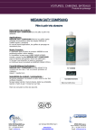
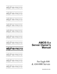
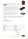
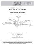
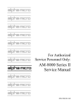
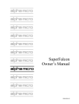
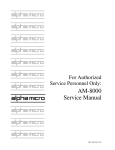
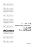
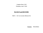
For Authorized Service Personnel AM-9000 Service Manual DSS-10629-00, A00 FIRST EDITION: January 2011 To re-order this document, request part number DSS-10629-00 FCC Notice This equipment has been assembled using components that have been certified under a Declaration of Conformity to comply with the limits for a Class B digital device, pursuant to Part 15 of the FCC Rules. These limits are designed to provide reasonable protection against harmful interference in a residential installation. This equipment generates, uses and can radiate radio frequency energy and, if not installed and used in accordance with the instruction manual, may cause harmful interference to radio communications. However, there is no guarantee that interference will not occur in a particular installation. If this equipment does cause harmful interference to radio or television reception, which can be determined by turning the equipment off and on, the user is encouraged to try to correct the interference by one or more of the following measures: Reorient or relocate the receiving antenna. Increase the separation between the equipment and receiver. Connect the equipment into an outlet on a circuit different from that to which the receiver is connected. Consult your reseller or an experienced radio/TV technician for help. Canadian Department of Communications Compliance Statement This equipment does not exceed Class A limits per radio noise emissions for digital apparatus set out in the Radio Interference Regulations of the Canadian Department of Communications. Operation in a residential area may cause unacceptable interference to radio and TV reception requiring the owner or operator to take whatever steps are necessary to correct the interference. Avis de Conformité aux Normes du Ministère des Communications du Canada Cet équipment ne deapsse pas les limits de Classe A d'émission de bruits radioélectriques pour les appareils numeriques tels que prescrites par le Règlement sur le brouillage radioélectrique établi par le ministère des Communications du Canada. L'exploitation faite en milleu résidential peut entrainer le brouillage des réceptions radio et tele, ce qui obligerait le propriétaire ou l'opératour à pendre les dispositions nécessaires pour en éliminer les causes. Battery Warning CAUTION: Danger of explosion if battery is incorrectly replaced. Replace only with the same or equivalent type recommended by the manufacturer. Discard used batteries according to the manufacturer's instructions. ATTENTION: Il y a danger d'explosion s'il y a replacement incorrect de la batterie. Remplacer uniquement avec une batterie du même type ou d'un type recommandé par le constructeur. Mettre au rébut les batteries usagées conformément aux instructions du fabricant. This computer contains a 3-volt lithium battery. When necessary, replace the battery with CR2032 type only. Use of other batteries may present a risk of fire or explosion. Replacement batteries may be ordered from your authorized Alpha Micro reseller. Electrical Warning This equipment contains components that can be damaged by static electricity. Follow all electronic discharge precautions when handling the equipment. For example, touch the metal back panel of the CPU or peripheral chassis to dissipate any electrical charge before touching the circuit boards or equipment within the chassis. After turning off power, before you open your computer chassis, unplug the cord from the electrical outlet to guard against electrical shock. SOFTWARE SECURITY DEVICE IDENTIFICATION NUMBER: _________________ The Alpha Micro Software Security Device (SSD) is a customized integrated circuit that personalizes the computer, providing identity verification for it. Certain Alpha Micro and non-Alpha Micro software may require that your computer contain an SSD in order to run software that has been customized to run only on your computer. Please enter the identification of your SSD above. The SSD identification number should be on your computer ID label under "SSD Serial No." (Another way of finding the number is to look at the SSD itself. The SSD is located in an integrated circuit location on the AM-9000 Multifunction I/O board; its identification number is printed on the SSD itself.) Software vendors may ask you for the SSD number if they are customizing software to run only on your computer. ALPHA MICROSYSTEMS 17534 Von Karman Irvine, CA 92614 Table of Contents INTRODUCTION........................................................................................................................1 ACCESSING YOUR COMPUTER.............................................................................................1 ELECTRONIC EQUIPMENT HANDLING PRECAUTIONS...................................................1 HARDWARE CONFIGURABLE OPTIONS .............................................................................2 AM-9000 CPU Board Configuration .......................................................................................2 Main PCIe x16 High Performance VGA Board.......................................................................4 CPU Cooler ..............................................................................................................................4 SSD Chip Removal...................................................................................................................6 AM-113-24 Control Panel Settings ..........................................................................................6 Replacing the Time and Date Battery ......................................................................................9 UPGRADING AM-9000 ON-BOARD MEMORY .....................................................................9 Removing Memory DIMMs .....................................................................................................9 Installing Memory DIMMs ....................................................................................................10 PERIPHERALS......................................................................................................................10 Additional Documentation for Peripherals ............................................................................10 System Administrative Tools .................................................................................................11 DISK DRIVE REPLACEMENT ...............................................................................................11 Adding another hard disk .......................................................................................................12 Create Acronis Image of the Wes7Boot C: Partition .............................................................14 Create Bootable DVD Backup ...............................................................................................15 Restoring the Wes7Boot C Partition ......................................................................................18 Restoring just one file from an "Acronis" backup .................................................................20 ON-LINE DOCUMENTATION ................................................................................................21 NEW FEATURES FOR AM-9000 SYSTEMS .........................................................................21 AM-9000 CONFIGURATION SCREENS ............................................................................24 APPENDIX A - AM-9000 OPTIMAL BIOS SETTINGS.........................................................30 BIOS Error Beep Codes .........................................................................................................33 Table of Figures Figure 1: Static Protection Wrist Strap ........................................................................................2 Figure 2: AM-9000 CPU Board Configuration............................................................................3 Figure 3: AM113-24 Parallel SSD and 4 SIO Board ...................................................................5 Figure 4: SSD Chip Removal Tool ..............................................................................................6 Figure 5: Disk Management .......................................................................................................13 Figure 6: Creating Duplicate Wes7 Boot Partition ....................................................................14 Figure 7: Acronis True Image Version 2011..............................................................................14 Rev. A00 AM-9000 Service Manual Page 1 INTRODUCTION This document contains instructions that are intended only for authorized service personnel. AM9000 computers contain a high-output power supply, which produces current levels high enough to make it unsafe for unauthorized persons to perform work inside the chassis. This document describes the AM-9000 computer packaged in the pedestal chassis, which can be optionally configured as a rack mountable chassis. It covers the following procedures: o Removing your computer's main access panel o Electronic equipment handling precautions. o AM-9000 CPU board configuration o High Performance VGA board o CPU Cooler o Installing the AM113-24 board & Control Panel settings o Installing memory o Peripheral installation & Disk drive replacement o Introduction to Acronis True Image for Backup and Restore o Restoring the AM-9000 System Boot partition o New Features of AM-9000 and Configuration screens o Main-board Optimal BIOS Settings o BIOS Beep Codes ACCESSING YOUR COMPUTER When adding additional equipment or servicing your computer, you will need to release two screws on the rear left side of the chassis, and then pull the side cover with the handle to remove it. This will expose the inside structure of your computer, including the power supply, main logic boards, and peripherals. ELECTRONIC EQUIPMENT HANDLING PRECAUTIONS With the AC power cord unplugged and the side cover removed, the components inside your computer are vulnerable to damage caused by static discharge. Your body and clothing can store an electrical charge that can damage or destroy unprotected electronic components. Before handling any computer hardware, make sure your work area is properly protected against static discharge. There are a number of commercially available static protection devices, like the wrist strap shown in Figure 1, designed specifically to protect your equipment from harmful static discharge. Rev. A00 Page 2 AM-9000 Service Manual Figure 1: Static Protection Wrist Strap HARDWARE CONFIGURABLE OPTIONS The following sections summarize the configuration options available to let you tailor your hardware to your needs. Most of these options require access to the main circuit boards inside the computer, and should be performed only by qualified technical personnel. Contact your VAR if you need assistance. AM-9000 CPU Board Configuration The AM-9000 CPU main-board is the primary board in your system. Most other boards contained in the system actually plug into the CPU main-board, including the memory DIMMs, system SSD 4-SIO board, and other special function boards. This board also contains the following circuitry: o o o o o o o o o One Intel XEON high speed processor Serial Attached SCSI (SAS) controller, with support for eight 6.0Gbps SAS ports Two Gigabit Ethernet communication ports Three DDR3 DIMM sockets (per CPU) supporting up to 24GB of ECC registered RAM 6 SATA drive ports with SATA II controller Two 9-pin serial I/O ports (with modem control) PS/2 keyboard and mouse ports CPU temperature and voltage monitoring Expansion slots for additional serial I/O and other specialized functions. AM-9000 CPU Board Configuration Figure 2 shows the AM-9000 CPU main-board configured as shipped by Alpha Micro. The standard jumper positions are listed along side the figure. All jumpers should be left in their factory configured positions. PRF-00328-00 is the part number for the main board without processor. PRB-00328-00 is the part number for the main board with processor. Rev. A00 AM-9000 Service Manual Shorting Block Configuration: JBT1 CMOS Clear JPC1/JPC2 SMB to PCI/PCI-E Slots JPG1 VGA Disable JPL1/JPL2 LAN 1/2 Enable JPRST1 Alarm Reset Enable JPS1 SAS Enable JWD Watch Dog Page 3 Open Open/Open Installed 2-3 Installed 1-2 Installed 1-2 Installed 1-2 Installed 1-2 Figure 2: AM-9000 CPU Board Configuration If you ever need to replace the AM-9000 CPU Board, you will need to enter the 12 digit CPU PIC number into the AM-9000 Configuration menu. The CPU PIC number is located on the CPU board at the right of CPU2 in Figure 2. Write this CPU PIC number down before installing the CPU board. The first time you boot up your AM-9000 after replacement of the CPU board, follow the procedure below to identify the new CPU board to the system software: Rev. A00 Page 4 AM-9000 Service Manual o Once the AM-9000 starts to boot, depress the and make sure the job is at command level. o Depress the ALT TAB key combination on the keyboard to display the AM-9000 System Diagnostic window. o Mouse click on Configure. The AM-9000 configuration screen will be displayed. o Move the mouse cursor over the “Magic Code” input box, click inside the box, and type in the 12-digit number of the CPU PIC you wrote down previously from the label on the new CPU board. o Depress RETURN on the keyboard. After a short period of time, if the CPU PIC installation was successful, you should see the message “Verification passed”. If you typed the wrong 12-digit number, the following error message should appear: CTRL C key combination for the boot job (VTM1) ?Magic code verification failed - please re-enter OK If this happens and you did not make a mistake typing the 12-digit number. Restart the system and verify the BIOS setting and then retry installing the CPU PIC. If this fails select the Control Panel. In the Address box, select the Down Select button. Browse to the C:\AM-9000 folder. Browse in the AM-9000 folder and find “amcfg.cfg” file. Email this file to [email protected] identifying who you are, what your system serial number is, and the CPU PIC that you entered. Main PCIe x16 High Performance VGA Board The main VGA video board is installed in the only PCIe x16 slot shown Figure 2 at the center of the board. This video board has 3 types of output connectors for use with the system Console monitor. Please keep the dust covers on the connectors when the individual connector is not in use. The part number for this board is PRF-00329-00. o o o VGA 15-pin D-Sub DVI HDMI CPU Cooler The high performance Xeon processor is a 130 Watt design. A proper CPU cooler is installed and powered from the main-board connector FAN1 in upper right hand corner. This is required to keep the 8-Core CPU cool. Please periodically clean the heat sink fins of dirt and dust bunnies. AM113-24 Parallel SSD and 4 SIO Board Configuration The AM113-24 board is a PCI compatible board and plugs into the 32-bit PCI slot on the AM-9000 CPU board. It contains the following functions: Rev. A00 AM-9000 Service Manual o o Page 5 SSD (Software Security Device) PLCC chip Four high performance serial ports, RJ-45 Alpha Micro standard pin-out Only one AM113-24 board may be installed in the AM-9000. The PLCC SSD chip pin 1 orientation is toward the mounting bracket. Factory default location will be PCI slot #1 at the bottom in Figure 2. Under Wes7 the board will enumerate the serial ports in either 32-bit slot on the CPU main-board. If you move the board to the other slot you must uninstall the previous installed configuration otherwise the port enumeration will start at the end of the previous installation. In other words it will renumber the ports from 3,4,5,6 to 7, 8,9,10. This will cause a problem with the AM9000.Ini file if you have them defined at the standard assignments of 3,4,5,6. Do this from Control Panel> Computer Management > Device Manager. The AM113-24 Parallel SSD 4 SIO board has been factory tested and shipped with its configuration jumpers set in their standard default positions, as specified in Figure 3. The nInt/Ext jumper is always open. JMP1 is installed in the lower position. All jumpers should be left in these factory configured positions. Nibble Jumper installed SSD Socket location 0 Serial I/O ports 0-3 3 Figure 3: AM113-24 Parallel SSD and 4 SIO Board Rev. A00 Page 6 AM-9000 Service Manual SSD Chip Removal The SSD chip is located at U3 on the AM113-24 SSD 4 SIO board, as shown in Figure 3. The SSD chip requires a special tool for chip removal. If you ever need to remove and replace this chip, be sure to use the correct tool, as shown in Figure 4. Figure 4: SSD Chip Removal Tool AM-113-24 Control Panel Settings Shown here is Wes7 Computer Management dialog with the Device manager expanded out for inspection. If you expand out the Multiport serial adapter and the Ports definition, you will see the properties pages and drivers used for the newly designed Parallel SSD and 4 SIO board. For Wes7 compatibility the driver is signed by Alpha Microsystems. Now left click on the PCI AM113-24 Parallel SSD. Rev. A00 AM-9000 Service Manual Page 7 The first dialog, the General tab shows which PCI bus the board is using. The port setting should always look like this. Do not change these settings. LPT numbers are 1,2 or 3. The signed windows driver is by Alpha Microsystems. Now for the serial ports, left click on the COM3 port. This is the first serial port on the AM113-24 board. This shows the bus location of the board. Rev. A00 Page 8 AM-9000 Service Manual This is the Driver Tab information. On the Settings tab you will see COM3 ports default settings. The actual baud rate is really controlled by the AM9000.ini file TRMDEF statements. To document the standard factory defaults the FIFO tab is shown. The Data Rate default settings should not be changed. Rev. A00 AM-9000 Service Manual Page 9 Replacing the Time and Date Battery When replacing the battery on your CPU board, always be sure to power-down the system first! DO NOT replace the battery with the power on! As always, when opening your computer chassis, take proper precautions against electrostatic discharge, which can seriously damage system components. The board uses one three-volt lithium battery (part #CR2032) that will last for approximately two to three years. To remove the existing battery, which is about the size of a quarter, you must slide it out from under the side spring contact. It may be necessary to press the spring latch toward the out-side edge to remove the battery from the plastic well that holds it in place. Do not use excessive force, or you will lose the contact tension and the battery backup will be intermittent. When installing the new battery, make sure the positive (+) side is facing up and the spring latch will contacts the right hand edge of the battery. After installing a new battery, the system BIOS setting will be reset to the main board defaults. See the following section for restoring your BIOS settings to those optimized for the AM-9000. Restoring Your BIOS Settings Besides the time and date, the AM-9000’s battery also maintains the system setup parameters and boot device parameters The BIOS parameters are stored in the AM-9000’s on-board BIOS chip. Therefore, when you remove and replace the battery, your BIOS settings will be lost. After you install the new battery and turn system power on, you need to access the BIOS Configuration menu by pressing DEL key during POST and restore your settings. Please refer to the Appendix A for the optimal settings. If you do not use the BIOS configuration menu to restore your settings, the system will drop into standard factory defaults and will boot slower because the parameters are not optimized for the system. Yet, when it does start to boot, the AlphaShell will boot the system with AM-9000.Mon and AM-9000.Ini as the system parameters. Once the system is up and running, log to OPR: and enter the current time and date. Reboot the system to initialize the system up time. UPGRADING AM-9000 ON-BOARD MEMORY In order to maximize system performance, the AM-9000 memory is always installed in pairs of DIMMs, allowing 128-bit interleaved memory operation. Always install memory beginning with CPU1_DIMM0 The AM-9000 CPU board has three on-board DIMM (dual inline memory module) slots, which support Registered DDR3 ECC RAM modules. Should you want to replace or upgrade any of these DIMMs, first remove the existing DIMMs, then install new ones, following the procedures below. Removing Memory DIMMs To remove a DIMM from its connector: 1. Press out on the retaining latches until the memory module pops up. Rev. A00 Page 10 AM-9000 Service Manual 2. Lift the DIMM out of the connector Installing Memory DIMMs The AM-9000 supports a minimum of 2GB to a maximum of 3.5Gb for Wes7 32bit, and 23GB for Wes7 64bit OS. The standard shipped software is the Wes7 32-bit version. Before attempting to install any memory, make sure that the memory you have is compatible with the AM-9000. Use Alpha Micro PFB-00727-H6 or equivalent memory to expand your system. To install memory expansion DIMMs in the AM-9000 CPU board, use this procedure: 1. Always install memory in order, starting with P1-DIMM1A (closest to the microprocessor CPU1 on the board). See Figure 2. 2. Make sure that the DIMM aligns properly with the memory slot. The modules are keyed to ensure that the memory DIMM is properly oriented. 3. Gently push the memory module into the desired slot. Once properly seated, the retaining latches on each end of the connector will close and secure the module into the slot. Sometimes you may need to close the latches yourself. After installing the DIMMs, the next time you power on the system, the memory will be detected. Currently, the maximum memory available to AMOS is 1200MB. This limitation is imposed by memory utilization by the Windows Embedded Standard 7 32bit OS. You may enter the AMOS RAM size in the General tab of the AM-9000 configuration screen. It has a data input box with the current allocation in MB displayed. We recommend 4GB of memory for the system with a maximum of 1200 MB for AMOS. Total Memory Installed 2 GB 3 GB 4 GB AMOS Maximum memory 750 MB 1000MB 1200MB PERIPHERALS The AM-9000 system cabinet can hold up to ten peripherals, making a wide range of configurations possible. The peripheral bays on the rack mount chassis are structured as follows: o o Seven 5-1/4” front accessible bays. The Blu-ray drive and system disk drive are mounted in this peripheral device area. Four 2-1/2” front accessible bays available with the SATA/SAS Disk Array mounting unit. Additional Documentation for Peripherals Each peripheral device sold by Alpha Micro is covered by its own set of installation instructions. The installation instructions include information on jumper settings, termination, and cabling. Before installing a peripheral, make sure you read the documentation pertaining to the device. Please look in the C:\AM-9000\DOC folder for additional documentation files stored there. Rev. A00 AM-9000 Service Manual Page 11 If the documentation was not included with your peripheral device, can be found on the Alpha Micro web site, www.alphamicro.com in the Documentation section. System Administrative Tools The following instructions list the screen titles, important options, and the actions you should take using the following syntax: <Screen or box Title or Application Program top line > <Selected item> action for you to do (keyboard input) (keyboard key) or <Selected item> mouse Select> {menu item} <Menu> action key press (keyboard) or <Menu> Select> {menu item} [scroll box] with mouse left click [Radio Button] mouse Select or ENTER or other Keyboard keys (Action notes and choices) Select> [program option] or Select> <Title> menu1> menu2> menu3> [program option] To select the last “program option”, you need to make multiple left button selects with the mouse of each menu number to reach the correct program selection. Accessing the AM-9000 Tools To use the AM-9000 System tools there are three ways to gain access. Use the Tools menu or typing the specific XCMD from AMOS on the console terminal. Press ALT TAB until the AM-9000 System Diagnostic screen appears. Press ALT T will open the <Tools> menu. Use the mouse to move over to the right hand side of the Console screen to access the program Start menu and System Tray utilities. Or while in AMOS on the VTM1 console terminal. Type XCP to launch the Control Panel application Type XPLORE for the windows explorer Type XDISKS to use the Windows Disk Management tool. This gives you access to various Win7 Embedded, Computer Management tools (for formatting disks, etc.) and to Acronis for creating "Bootable Backup Recovery DVD” and other data backups. The system administrator should know how to use Windows utilities and how to use Acronis software. DISK DRIVE REPLACEMENT There are a few situations that will require the system administrator to work with disk drives and DVD or Blu-ray media to restore the system boot partition. All these procedures must be done on the system console. o Adding another hard disk. o Restoring the AM-9000 to a new or empty formatted hard disk. o Restoring just one AMD files from an Acronis partition backup. Rev. A00 Page 12 AM-9000 Service Manual Before beginning any of these procedures, make sure you have a current AM-9000 “Bootable Data Recovery DVD”. PLEASE backup the current System Wes7Boot Partition and Data Partition to alternate media. Accessing the AM-9000 Disk Management screen Many of these administrative tasks require access to the AM-9000 Disk Management screen. On the console terminal type XDISKS to start the application or follow the procedure below. You may also use you mouse to point the Menu Item and click to select. The manual keyboard method is outlined below. Press to: <AM-9000 System > Press ALT T (opens Tools) Press to:{Control Panel} Press ENTER <Control Panel> Select > View by Small Icons on the right With mouse Double click on {Administrative Tools} <Administrative Tools > Double click on {Computer Management} <Computer Management> Press to {Storage} Press Press to: {Disk Management} Press ENTER ALT TAB Use the arrow keys to move between the various drives (usually Disk 0 and Disk 1). The and will select various partitions on each Disk. You should see each physical drive or drives on the system with drive sizes and partition sizes. Adding another hard disk When adding another hard disk drive there are some additional steps necessary before loading software: Physically install the new hard drives in the drive bays available in the rack/tower chassis. All SAS drives must be connected to one of the SAS ports off the main CPU board (black connectors). Once a drive is installed, on power up you must reconfigure the BIOS Drive Boot order. This model motherboard selects SATA drives first, then SAS drives. Usually you want to boot from the fastest SAS drive in your system as 1st boot Drive. The SATA drives can be connected to either a SAS port or the SATA2 ports (blue connectors). If the disk drive has an SATA2 interface, it can go on any of the 6 SATA ports. Once you add a new drive to the system that is not formatted, it will be displayed in the lower panel with a Black Bar in the Disk Manager application. First, you must allocate a partition. Configure the new drive by either: a. Manually allocating the drive partitions and format each partition from Disk Management console, or; b. Do an Acronis partition restore of a recent backup to the new hard disk primary active partition to make it bootable. c. See the “Restoring the AM-9000 Wes7 Boot C: Partition”. Rev. A00 AM-9000 Service Manual Page 13 Once you add a new drive to the system that is not formatted, it will be displayed in the lower panel with a Black Bar. First, we must allocate a partition. Figure 5: Disk Management 1. Right click on Disk 1 black bar in the lower panel and Select> {New Partition} 2. The < New Partition Wizard> will display. Select> [Next]. 3. <Select Partition Type> Select> {Primary partition} > [Next]. (you can only boot off of a primary partition) 4. <Specify Partition Size> the Partition Size in MB type in 30725 select> [Next] button. 5. Allow the program to assign the next drive letter. Select> [Next] button. <Format Partition> { Format this partition with the following settings:} File System: NTFS Allocation unit size: Default Volume Label: type in (Wes7Boot2) Check the {Perform a Quick format box}. Select > [Next] button. Select > [Finish] button. 6. Now repeat the above steps for the OSBackups partition size of 40960 MB. 7. Now create the final DataVol with the remaining disk space. 8. To set the new Wes7Boot Active right click on G: and Select > {Mark Partition as Active} 9. When Wes7 finishes formatting the drive, the display will look like Figure 6. Rev. A00 Page 14 AM-9000 Service Manual Figure 6: Creating Duplicate Wes7 Boot Partition Now to configure the new drive for AM9000 operation we need to use Acronis True Image recovery to place the contents of the Wes7Boot(C:) partition on G: This can be done doing a partition recovery. Create Acronis Image of the Wes7Boot C: Partition This can be accomplished by booting from the provided AM-9000 Data Recovery DVD and perform a Backup of the C: partition. A Clone of the primary drive is another alternative. The third way is to launch the Acronis True Image from Wes7 tool bar on the right side of the screen. The toolbar has auto hide set so move the mouse cursor over to the right hand edge of the screen and it should pop up. Move up to the top right hand corner of the screen and click on the Windows Start Icon. The program menu should be displayed and select Acronis True Image software shortcut. Figure 7: Acronis True Image Version 2011 The backup process is very easy. The menus are easy to read and follow. There is also Help available in the upper right hand corner of the dialog box. This will bring up a complete help system with all topics covered. Rev. A00 AM-9000 Service Manual Page 15 Backups can be made on many different media types. We have tested the following with success. o o o o Blu-ray BD-RE, DVD-RW, DVD-RAM, DVD-R, CD-RW USB Flash sticks of 4Gb, 8Gb, 16Gb formatted in NTFS USB Hard drives of various sizes SATA hard drives in removable trays To create a bootable recovery media on DVD-RAM, DVD-RW, DVD-R, BD-RE make sure when you select the DVD drive icon, check the checkbox next to the message { Make this media Bootable } Any hard drive can be used to create and store backup images. The D: OSBackups partition is used for this purpose. A folder called OSBackups is where the C boot partition images are stored. A removable SATA drive tray can also be used to store backups. This allows the user to change the drive and take the backup data off site. Another location that can be used as a storage destination is a mapped network drive. You can create a backup task for this location. This is the slowest backup option available to you. It also ties up the network while the data transfers. You may also create a {File Backup} from the main menu. This is listed under {More Features} You can select any folder or disk partition from the pop up menus. Make sure you destination drive is not selected to be contained in the backup. If you have an exact size disk drive you may “ Clone “ your source drive. This process is accessible from the Tools & Utilities link in the task bar. Follow the menus to accomplish the task. Now let us create a boot partition backup task. Create Bootable DVD Backup Now let us create a boot partition backup to a DVD-R media. First select Disk and partition backup. Place a DVD-R media into the DVD drive. Rev. A00 Page 16 AM-9000 Service Manual This is the pop up menu that appears. Now click on the check box to the left of Wes7C300Boot0: The estimated backup size is shown here. Next click on the check box {Make this media Bootable} Now move the mouse down to Destination box down Arrow and select F:\ as shown here. Rev. A00 AM-9000 Service Manual Page 17 Type in a Name of the backup in the {Backup name:} entry box. Here we say 9KSn101SasBoot(c)Jan5, which makes some sense to describe the System type, serial number, boot volume and when it was made. Now click on [Back up now] button. A DVD-R media backup normally takes about 10 minutes to write. True Image will create a new backup of the Wes7C300Boot partition with bootable data onto the DVD-R media. When complete you may access the log file by clicking on the little blue down arrow to the right of Help in this screen. Select log file in the pop up menu. Double click on the first entry in the list and use the scroll bar to inspect the contents. You can create other backup tasks that can place the backup on Bootable DVD, or Blu-ray media. You can also write the backups directly to SATA, USB drives or USB sticks directly if there is enough room. As always, read the screen carefully and verify where you’re writing the data is where you think. Read thru Acronis Help screens if you have more questions. The online help screens are very useful. Here is a sample of some of the backups created on an Eagle 900 system. Rev. A00 Page 18 AM-9000 Service Manual Data backups created on the Crucial C300 device or on SATA or SAS devices are shown here. A typical backup of the C boot volume takes about 3 minutes. The Data volume backup is dependent on the amount of data being compressed into the image backup. Restoring the Wes7Boot C Partition The most reliable method of restoring the boot partition operating system to a new disk drive must be done from the bootable Acronis Data recovery DVD provided, or from the one we just made above. You should only have one hard drive plugged into the SAS controller. This is your new drive you have pre-formatted ready to use. 1. Place the Bootable Recovery DVD into the DVD drive and hit the reset button. Allow Acronis to boot from the DVD and press a space bar to accept to boot from DVD. When the first screen appears, select { Acronis True Image Full Version } and hit return. Allow Acronis 2011 boot up. The main screen should appear. Select with the mouse [ Recovery ] and left click. The Disk Recovery screen should appear. 2. Click on the [ Browse for backup ] button. A browser window will appear. In this window either select the CD drive or browse to [ OSBackups ] double click to expand. Double click on [OSBackups] Rev. A00 AM-9000 Service Manual Page 19 folder. Find and select with the mouse [ AM9kSn101_C300Boot2011-01-04.tib ] file and click on the [OK] button. 3. In the Images display, Find the Wes7BootC partition symbol and right Click, select [Recover]. The Recovery method should select { Recover disk and whole partitions } Click on [Next] 4. On select items to recover menu, click on ONLY the box to the left of { NTFS (Wes7BootC) Primary, Active }. Click on the [Next] button. 5. Now the Specify recover setting of Partition C will display. { New Location } In Partition Destination dialog click on the {NTFS (Wes7BootC) Pri, Act 30Gb partition} should highlight in Blue. Click on the [Accept] button. 6. Under Partition Type: you should have displayed { Primary, Mark partition as Active} 7. Under Partition Size: { 30Gb } should display, Click on [Next] button. 8. The Summary Page, you should review that all the settings are correct. Click on [Proceed] button. When it finishes, click [OK] then Click on the Red [X] to close the program. The Acronis Restore process is normally used when a new replacement hard drive is installed. After the restore all system settings and configuration settings must be re-entered for the AMOS Server installation. The Bootable Acronis Recovery DVD shipped from Alpha Micro has the default settings and the original disk files. Any patches or Customer data applied to the Server after installation will be missing. The system administrator should perform an Acronis backup to a file of the C: Wes7BootC partition any time there is a configuration change to the Server. This up-to-date backup will contain all the information about the specific installation. Then this backup should be copied to alternate media and labeled and stored for future use. If the boot AMD disk file was on the first disk partition, then the customer’s AMD disk files will have to be regenerated and the application software restored back onto the system drive. If the system administrator places the AM9000.AMD boot disk on the E drive, it will also have to be restored from the Rev. A00 Page 20 AM-9000 Service Manual D: Data Volume backups. After an Acronis restore to a new disk drive, if you have additional backups of just the AMD disk files then you are safe. These AMD files will need to be copied to the correct locations and then Configured in the AM9000 program as described in Chapter 3 of the AMOS 8.x Servers Owner’s Manual. Getting to a Production Configuration If you had changed any of the AM9000 configuration information since creating the bootable backup DVD, such as adding Microsoft Network printers, COMxx ports, SCSI devices, firewall settings, etc., then you will need to repeat those changes. In addition, the AM9000.INI, and other customized .INI files, and perhaps even the AM9000.MON, may not be current. Production versions are normally on the AMOS 8.2 AMD disks on the "Data Volume". AFTER restoring the latest backup (see below), these can be updated by simply MONTSTing from the latest backup copies - like MONTST AM9000 which will re-syncronize the "System partition" copies. If the "Data Volume" partition (usually E:) was restored, then restoring the production system is done. If this was the most recent backup of the AMOS data, then the whole procedure is done. If there is no "Data Volume" (it was not on the backup), then create a data volume using the New Partition Wizard described earlier in this manual. If necessary, create an AMOS AMD pseudo drive using the AM9000 configuration process described in the AM-9000 Server Owner’s Manual. Generally we recommend disks of 4 GB or less so that each will fit on a DVD-RAM media. However, the choice is yours: Using a large disk drive with the Acronis compression will allow backing up much larger AMD files. Proceed with restoring the last AMOS backup as appropiate to the backup procedure used. Then, as mentioned above, use MONTST to re-syncronize the "System Volume" copies of the important .MON and .INI files. If you used the above procedure to install a “sub-system” drive, you can change the motherboard BIOS settings to boot off of the newly defined disk drive. Restoring just one file from an "Acronis" backup This feature will work from a “Partition Image” stored on a hard drive. To get to the files inside of a TIB image, just double click on the “TIB” file and windows explorer will mount the image and you can then drill down in the directory to find and copy any file from the backup. The other option available is to create a “File Backup.” This type you must restore the complete backup created to the original folder or Alternate location. If the File-Backup image is stored on a hard drive, it also may be mounted as an Acronis disk and copy individual files from it. Make sure that the destination disk drive that has enough space for the files that were backed up to be restored. This type can compress the folder files into a more manageable size that can be place on a USB stick, USB drive or over the network on another server. If you want to access a few files from an Acronis Partition backup, you can copy the appropriate AMD file from the Acronis backup to the hard disk. Then configure this copy of the AMD file as a sub-system drive in the AM9000 AMOS Disks configuration screen, and if necessary, add it to the booting INI file. You may use the XMNT Dev: if the Dev: name is a AMD disk driver loaded into system memory. This is the hot swap feature of AM9000. Then you can access all of the AMOS files in the AMD drive disk file. Rev. A00 AM-9000 Service Manual Page 21 The special part is getting the AMD disk file from the Acronis backup. This is done using the Acronis Explorer. Open up windows explorer and browse to the D:\OSBackups folder and double click on the “TIB” file you wish to recover from. Once Acronis Explorer is open then double click on the appropriate drive letter. Find and select the desired AMD file. Right click and COPY. Browse to your desired disk drive location that has enough room for this file, Right Click and paste. Remember that if AMOS is active and the filename of the disk file being recovered is the same as the one open, Acronis Explorer will not be able to restore to the same location. Exit AMOS and then you may write the disk file back to the active location. It is always safer to restore to an alternate location. ON-LINE DOCUMENTATION There is on-line documentation on each system. The Adobe Acrobat Reader is also installed on the system and can be used on the Console to review the PDF documentation files. To access the PDF files, use the Control Panel interface to browse to a directory and find the PDF file you desire to read. Double click on the PDF filename and the Acrobat reader will launch and display the document. An alternate way is to type PDF from VTM1 console terminal. This will display the latest PDF files stored in the DOC folder under AM-9000. Other files you can search for with Windows Explorer. We highly recommend that you read the Acronis Guide on the workings of this useful Backup and Restore utility. NEW FEATURES FOR AM-9000 SYSTEMS There are many new features to the AM-9000 system. We will try and describe these features here. The new underlying control program is Windows Embedded Standard 7 (Wes7). There are a few programs that will automatically load at boot time which will bring up the system in the AM9000 operating system. The AlphaShell will auto boot up AMOS by executing C:\AM9000\AM9000.exe. HotSwap!exe is another program that allows you to swap in and swap out SATA hard drive to the system while AMOS is booted. To locate this program, move the mouse over to the right hand edge of the console screen until the Task bar will appear from it’s auto-hide state. In the lower right hand corner you will see some icons in the system tray. Slide in your SATA hard drive and lock into place. Right click on the Red arrow icon here. Then left click select “Scan for hardware changes”. When you execute windows explorer you should now see drive labels for the new backup SATA drive. Before you un-mount the device, verify all write processes have finished so you will not damage the data on the drive. To safely un-mount a drive in the SATA tray. Left click on the Red arrow Icon and you should see a pop up display of the drives that are allowed to be swapped out. Left click on this window to select and un-mount the drive. Then remove it from the SATA tray as the off site backup device. Rev. A00 Page 22 AM-9000 Service Manual To safely un-mount a USB device left click on the USB plug and green check mark icon above. It will identify what USB devices can be un-mounted. The system current Date and Time is shown next to the bottom right corner. Below it is a rectangle, if you click on it, the Desktop will be displayed. If for any reason the system tray is always shown, it indicates that some process is started, or finish and usually a icon will display in the system tray, or click on the white left arrow to pop up a menu of the pending process. The Green house with flag is the Microsoft Security Essentials icon. Click on it and you can execute a system scan for virus. Please select the update tab to verify you have the latest definition file from Microsoft. The Blue Eye ball icon is the Ultra-VNC software application. To see what your IP address of Wes7 system, move the cursor over the eye and a pop up will display the address. To manage the program settings right click select {Admin Properties}. The VNC password box is set to “am9k” as the default. If you move the mouse over the Console icon, you internet access and company name should appear. If you left click on the white flag icon you can access the Wes7 Action center. Security and Maintenance menus can be executed from here. If click on the yellow folder icon at the top of the system tray, you will bring up Windows Explorer. Another feature you should notice about this display are “Program Libraries.” These are already set up for the AM-9000 system. [AM9000_Documents] is the PDF, DOC and Help files for the system. [AM9000_Files] is the main AM9000 folder with all folders and programs specific to AM9000 functionality. [AMD_Files] is where you should place customer AMD files, which is normally located in E:\DataVol\AMD_Files folder. [OSBackups] is where Acronis True Image files for the Boot partition should be stored. This is located in D:\OSBackups\ folder. D:\OSBackups\FileBackups is also where you can backup your AMD files if they are small enough to fit on the D: partition. Otherwise place them on swappable USB or SATA drives. [SataBackupsW7] is located on the swap tray SATA drive. You may backup directly to here for off site backup capability. [Win7Files] library is a folder under AM9000 and have some of the driver files and support programs for the AM9000 system. The Kingston F: drive here is a USB Flash drive used for backups. Rev. A00 AM-9000 Service Manual Page 23 To locate your system serial number right click on Computer, then select the program link in the program header “System properties.” Windows activation is also shown here with the ‘Genuine Icon” You may also get to the device manager from the program link on the left panel. Remote desktop is now available under windows 7. The password to logon or access the system is “am9k”. To work with the network properties left click the PC terminal icon here. Then left click on “Open Network and Sharing Center” from the popup menu. In the left panel you can click on “Change adapter settings” to set a fixed IP for the AM9000 server. On the next pop-up menu select the “Local Area network” The Local Area Network status window will appear. Click on the [Properties] button. Rev. A00 Page 24 AM-9000 Service Manual The properties page will display, scroll down in “This connection uses the following items” window and locate and left click select “TCP/IPv4” to highlight in blue. Then click on the [Properties] button. Then click on the radio button “Use the following IP address” and fill in setting to assign the Wes7 IP address and the Router Address in “Default gateway”. Under Preferred DNS server, fill in the installation’s DNS primary IP address. Then click on the [OK] button. Then click on [Close] button. The next menu displayed, click on [Close]. Then Reboot the system to have the setting saved to the registry. The AMOS assigned IPs are assign in TCP: Netwrk for the AMOS host and Config file for the router address. The other new feature is the Acronis True Image 2011 software package to replace the older Ghost 2003 software which will not function under Wes7. True Image will be used to create Partition backups for the boot partition and can be used for data backups as well. There are many options for backup with the new system. The XBAKUP.do file from AMOS will also backup your AMD files to USB or other SATA or network drives. This is user controlled by the C:\AM9000\Win7\Backup.Bat file. Please edit this file to define the source files to backup and the destination folder for this task. Adobe reader 9.4 is installed to allow access to all PDF files on the system. Microsoft Office Word Viewer is installed so you may read any *.DOC file on the system. Hasher is installed so if you select a file in explorer and right click you can select the Hash program. Rawether is installed for network driver along with Visual C++ 2008 runtime to allow AM9000 exe to access the network interface. The TweakNow PowerPack tools are installed to customize Wes7 for AM-9000 installations. The Alpha Micro sign on screens and bitmap images for desktop backgrounds are also installed on the system. AM-9000 CONFIGURATION SCREENS A new look for Wes7 for the AM9000 configuration screens with version 1.2(959). The main diagnostic screen shown here has a few new items. The new AM-113-24 SSD board with serial ports will auto detected its’ base address is shown. If the SSD is plugged in and the Magic Code is installed, it will display the SSD signature. The board is accessed thru a software driver called TVicHW32. Rev. A00 AM-9000 Service Manual Page 25 The new Archimedes Cache memory assignment is also shown here as the system boots up AMOS. You may access the Wes7 Control Panel or Task Manger from selecting the {Tools} link in the program header. The Acronis True Image Backup software can also be executed from this pop-up menu. To Configure AM9000 select {Configure} from the program link shown above. The AM9000 configuration has multiple tabs one for each program feature. The General tab shown displays the settings for AMOS memory Size and the new Archimedes Disk Cache memory size. For Archimedes Cache Technology to be active this number must be greater than 5Mb and no larger than 512Mb. Most typical installation can use a value of 100 to 400Mb. So a system with 4Gb of installed memory with 900Mb for AMOS and 400MB for Archimedes cache produces an active memory in use of 3063Mb. Maximum memory available is 2.99Gb allowed by Wes7 with 4096Mb of installed memory. If your memory configuration is too large AM9000.exe will abort the boot process. Rev. A00 Page 26 AM-9000 Service Manual The Magic code that is installed for the system is saved in the Registry and now is displayed to the right of it’s input box. Job context switch value should be between 1000 and 2500. The “Disable WindowsAMOS date time syncronization allows the system operator to check this box and can set a date and time from OPR: that is different than the Windows time that is current and battery backed up. The other items have not changed from the AM8000 version. When you select the AMOS Disks tab you will be able to define any AMD file to the system. The PC Data file name box has been lengthened. The [PageDown] button will allow you to configure up to a total of 50 definitions. Your Primary AMOS boot disk is always defined to the right of the “DSK” device specification. You can use any 3 letter abbreviation for an AMD file. These definitions must have an AMOS driver definition in the SYSTEM statements of the AM9000.INI file. This is always a copy of the PCDSK.DVR[1,6] file. If the driver is defined in the System statements it does not have to have a Devtbl or Bitmap statement. This feature is called AMOS HotSwap AMD files. As long as you define 20MB or more to SMEM, the Devtbl and Bitmaps are allocated during the XMOUNT from SMEM area. A DO file called XMNT is normally used to Mount and allocate the swap disk. To un-mount the device make sure no user is logged into the swap device, then type XMOUNT Dev:/u. Rev. A00 AM-9000 Service Manual Page 27 The Virtual console terminals are shown here. You can use the default setting of AmpcLite or AmpcTerm for the VTM jobs. If you purchase a full version of AlphaLan 9.0++ it also can be used on the console. It has a restriction, only ONE job can be defined with the terminal emulator. The /Local switch must be typed into the command line following the program location. It can be installed into it’s own Alan folder under AM9000 or can use the default location installed under Program Files, but the path specification must be exact for this to work. The default.Aln file must also reference the program location. The new AM113-24 board is now mapped as PC-Com ports. They are mapped to an AMOS port with left click and hold the defined port in the left panel and slide over to the right panel left click release and drop onto the desired port definition. The main board port is PC Com1, 2 and the AM11324 ports are 3,4,5,6. If you add an addition PCIe serial board or USB-serial port adapter they also must be assigned for AMOS use here. If the serial port is defined as a PC controlled device like a PC serial printer, it does not have to be defined here. In Wes7 control panel set up a serial printer then this printer can be mapped as an LPT printer to AMOS. Make sure the printer prints from Windows first before defining it in the AM9000.ini file as LPTx device. Rev. A00 Page 28 AM-9000 Service Manual The newly revised Printers page is shown here. A new [Clear] button allows the user to clear out the LPTx assignment from the registry. Raw mode acts as with the Am8000 version. If not checked you may define a printer with a specific font and font size. This is done thru the windows printer property pages. As in previous versions, all 16 printers defined here are not counted as an AMOS user license. They are defined to AMOS as a LPT job using the PCLPT interface driver. Please refer to the owner’s manual chapter 6 for more information. The Network adapter to be usable under AMOS must have a double yellow arrow head next to it. If it does not have this arrow head just double click on the Adapter you wish to use. A system could have more than one adapter. The standard system shown here is correctly configured. Rev. A00 AM-9000 Service Manual Page 29 The SCSI devices are shown here. The ATAPI DVD drive or Blu-Ray drive must be mapped for AMOS use as shown here. This will allow DVD and Blu-ray software to function under AMOS. The normal left click select in the above panel and drag and drop on the AMOS device number to use in the lower panel. If you install a Streamer tape drive it will be listed in the above panel and needs to be mapped as an AMOS SCSI device in the lower panel. Then modify the AM9000.ini file and add in a Devtbl /Str0 and System Dvr:Str.dvr statements. Rev. A00 Page 30 AM-9000 Service Manual APPENDIX A - AM-9000 OPTIMAL BIOS SETTINGS To Enter Setup press DELETE during the POST process to enter the motherboard BIOS Setup. Use arrow keys to move the cursor to highlight the field to change. The items in Bold are the settings need to be changed from the default settings. [MAIN] System Time System Date [08:24:00] [Mon 12/14/2010] [ADVANCED] [Boot Features] Quick boot Quiet Boot AddOn ROM Display Mode Bootup Num-Lock PS/2 Mouse Support Keyboard Error Report Wait for 'F1' if error Hit 'DEL' MessageDisplay Watch Dog Function Power Button Function Restore on AC Power loss Interrupt 19 Capture [Enabled] [Disabled] [Force BIOS] [On] [Auto] [Disabled] [Disabled] [Enabled] [Disabled] [4 Sec Overide] [Power-On] [Enabled] [Processor & Clock Options] CPU Ratio Ratio CMOS Setting Clock Spread Spectrum Hardware Prefetcher Adjacent Cache Line Prefetch MPS and ACPI MADT ordering Intel Virtualization Technology Execute-Disable Bit Capability Simultaneous Multi-Threading Active Processor Core Intel EIST Technology Intel TurboBoost Technology C1E Support Intel C-State Tech C-State Package Limit Setting C1 Auto Demotion C3 Auto Demotion ACPI T State DCA Technology CDA Prefetch Delay [Auto] [19] [Disabled] [Enabled] [Enabled] [Modern Ordering] [Enabled] [Enabled] [Enabled] [All] [Enabled] [Enabled] [Enabled] [Enabled] [Auto] [Enabled] [Enabled] [Disabled] [Enabled] [32] Rev. A00 (replace with actual time) (replace with actual date) AM-9000 Service Manual [ Advanced Chipset Control ] [ QPI & IMC Configuration ] QPI link speed QPI Frequency QPI L0s and LI Memory Frequency Memory Mode Demand Scrubbing Patrol Scrubbing Channel Interleave/Bank Interleave Throttling Closed Loop Hyster Temp Guardband Temp Intel Temp Temp Rise Air Flow Altitude DIMM Pitch Intel VT-d SR-IOV Support NUMA Support Intel IOAT Active State Power Management USB Functions USB 2.0 Controller Legacy USB Support [ IDE SATA Configuration ] SATA#1 Configuration Configure SATA#1 as ICH RAID Code Base SATA#2 Configuration IDE Detect timeout Primary IDE Master/Slave Type LBA/Large Mode Block Transfer PIO Mode DMA Mode SMART Mode 32Bit Transfer [PCIPnP Configuration] Clear NVRAM Plug & Play O/S PCI Latency Timer PCI IDE BusMaster PCI-Express IO Performance ROM Scan Ordering Page 31 [Full Speed] [Auto] [Disabled] [Auto] [Independent] [Disabled] [Disabled] [4 Way] [Disabled] [Disabled] [006] [070] [020] [1500] [Sea Level] [400] [Disabled] [Disabled] [Disabled] [Enabled] [Disabled] [12 USB Ports] [Enabled] [Enabled] [Enhanced] [IDE] [Intel] not used normally [Enhanced] [35] [Auto] [Auto] [Auto] [Auto] [Auto] [Auto] [Enabled] [No] [No] [64] [Enabled] [128B] [Onboard First] Rev. A00 Page 32 PCI Slot Control Onboard LAN option ROM Select Load Onboard LAN1 option ROM Load Onboad SAS option ROM Boot Graphics Adapter Priority AM-9000 Service Manual [Enable] used to disable or enable individual slots [iSCSI] [Disabled] [Enabled] [Other] to enable PCIe graphics card [ SuperIO Configuration ] Serial Port1 Address Serial Port2 Address Serial Port 2 Attribute [3F8/IRQ4] [2F8/IRQ3] [COM] [ Remote Access Configuration ] [Disabled] [ Hardware Health Monitor ] CPU Overheat Alarm System Temperature Fan Speed Control Modes [Default Alarm] [Fans 1 thru 8] [Balanced/BL] [ ACPI Configuration ] High Performance event timer PS2 KB/MS wake up ACPI aware OS ACPI APIC Support APIC ACPI SCI IRQ Headless mode ACPI Version [Enabled] [Disabled] [Yes] [Enabled] [Disabled] [Disabled] [ACPI v2.0] [ Trusted Computing ] Indicate Physical TPM Deactived TPM Owner Execute TPM Command [No] [Don’t Change] [Don’t Change] [Don’t Change] [ IPMI Configuration ] [Event Log Configuration ] View Event Log Mark All events as read Clear Event Log Event Log Statistics [SECURITY] Settings Supervisor Password is: User Password is: Change Supervisor Password Change User Password Boot Sector Virus Protection [ Boot Device Priority ] 1st Boot Device/2nd Boot Device Rev. A00 [Not Installed] [Not Installed] [Enter new password] [Enter new password] [Enabled] AM-9000 Service Manual Page 33 [Hard Disk Drives] 1st Drive 2nd Drive 3rd Boot Device 4th Boot Device [DVD/BluRay] [SCSI:#200 ID18 LUN] [Sata:0 Seagate] [Disabled] [Disabled] [Removeable Drives] [CD/DVD Drives] Retry Boot device [DVD/BluRay] user selectable [Select Blu-Ray drive] [Disabled] [ EXIT ] Save Changes and Exit Discard Changes and Exit Load Optimal Defaults Load Failsafe Defaults BIOS Error Beep Codes Code 1 Beep Error Message Refresh, Circuits have been Reset, ready to Power up 5 Short Beeps + 1 Long Beep Memory Error, No Memory detected in system. 8 Beeps Display memory read/write error, Video Adpater missing or with faulty memory. 1 Continuous Beep System Overheat Shut down and cool off. Rev. A00