1
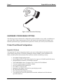
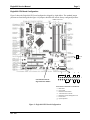
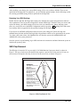
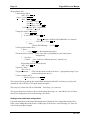
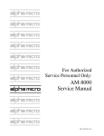
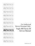
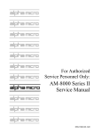
For Authorized Service Personnel Only: Eagle 800 Service Manual DSS-10621-00, A01 FIRST EDITION: November 2003 A01: September 2004 To re-order this document, request part number DSS-10621-00 FCC Notice This equipment has been assembled using components that have been certified under a Declaration of Conformity to comply with the limits for a Class B digital device, pursuant to Part 15 of the FCC Rules. These limits are designed to provide reasonable protection against harmful interference in a residential installation. This equipment generates, uses and can radiate radio frequency energy and, if not installed and used in accordance with the instruction manual, may cause harmful interference to radio communications. However, there is no guarantee that interference will not occur in a particular installation. If this equipment does cause harmful interference to radio or television reception, which can be determined by turning the equipment off and on, the user is encouraged to try to correct the interference by one or more of the following measures: • Reorient or relocate the receiving antenna. • Increase the separation between the equipment and receiver. • Connect the equipment into an outlet on a circuit different from that to which the receiver is connected. • Consult your reseller or an experienced radio/TV technician for help. Canadian Department of Communications Compliance Statement This equipment does not exceed Class A limits per radio noise emissions for digital apparatus set out in the Radio Interference Regulations of the Canadian Department of Communications. Operation in a residential area may cause unacceptable interference to radio and TV reception requiring the owner or operator to take whatever steps are necessary to correct the interference. Avis de Conformité aux Normes du Ministère des Communications du Canada Cet équipment ne deapsse pas les limits de Classe A d'émission de bruits radioélectriques pour les appareils numeriques tels que prescrites par le Règlement sur le brouillage radioélectrique établi par le ministère des Communications du Canada. L'exploitation faite en milleu résidential peut entrainer le brouillage des réceptions radio et tele, ce qui obligerait le propriétaire ou l'opératour à pendre les dispositions nécessaires pour en éliminer les causes. Battery Warning CAUTION: Danger of explosion if battery is incorrectly replaced. Replace only with the same or equivalent type recommended by the manufacturer. Discard used batteries according to the manufacturer's instructions. ATTENTION: Il y a danger d'explosion s'il y a replacement incorrect de la batterie. Remplacer uniquement avec une batterie du même type ou d'un type recommandé par le constructeur. Mettre au rébut les batteries usagées conformément aux instructions du fabricant. This computer contains a 3-volt lithium battery. When necessary, replace the battery with CR2032 type only. Use of other batteries may present a risk of fire or explosion. Replacement batteries may be ordered from your authorized Alpha Micro reseller. Electrical Warning This equipment contains components that can be damaged by static electricity. Follow all electronic discharge precautions when handling the equipment. For example, touch the metal back panel of the CPU or peripheral chassis to dissipate any electrical charge before touching the circuit boards or equipment within the chassis. After turning off power, before you open your computer chassis, unplug the cord from the electrical outlet to guard against electrical shock. SOFTWARE SECURITY DEVICE IDENTIFICATION NUMBER: _________________ The Alpha Micro Software Security Device (SSD) is a customized integrated circuit that personalizes the computer, providing identity verification for it. Certain Alpha Micro and non-Alpha Micro software may require that your computer contain an SSD in order to run software that has been customized to run only on your computer. Please enter the identification of your SSD above. The SSD identification number should be on your computer ID label under "SSD Serial No." (Another way of finding the number is to look at the SSD itself. The SSD is located in an integrated circuit location on the Eagle 800 Multifunction I/O board; its identification number is printed on the SSD itself.) Software vendors may ask you for the SSD number if they are customizing software to run only on your computer. ALPHA MICROSYSTEMS 17534 Von Karman Irvine, CA 92614 DSS-10621-00, A01 Table of Contents INTRODUCTION..........................................................................................................1 ACCESSING YOUR COMPUTER.........................................................................................1 ELECTRONIC EQUIPMENT HANDLING PRECAUTIONS ................................................1 HARDWARE CONFIGURABLE OPTIONS ..........................................................................2 Printed Circuit Board Configurations ...................................................................................2 Replacing the Time and Date Battery ...................................................................................5 SSD Chip Removal..............................................................................................................6 UPGRADING EAGLE 800 ON-BOARD MEMORY..............................................................7 Removing Memory DIMMs .................................................................................................7 Installing Memory DIMMs ..................................................................................................7 PERIPHERALS ......................................................................................................................8 Installing Additional 3-1/2” Peripherals ................................................................................8 Installing Additional 5-1/4” Peripherals ................................................................................8 Additional Documentation for Peripherals ............................................................................9 DISK DRIVE REPLACEMENT AND WARMBOOT RESTORE ..........................................9 System Administrator Tools .................................................................................................9 Formatting DVD-RAM Media ........................................................................................... 11 Adding another hard disk ................................................................................................... 11 Restoring the Eagle 800 to a fresh or wiped hard disk (warm boot). .................................... 13 Restoring just one .AMD file from a "Ghosted" backup ...................................................... 15 ON-LINE DOCUMENTATION............................................................................................ 15 APPENDIX A - EAGLE 800 OPTIMAL BIOS SETTINGS.................................................. 17 MN31N Motherboard ........................................................................................................ 17 MN31L Motherboard......................................................................................................... 19 Table of Figures Figure 1: Static Protection Wrist Strap ....................................................................................2 Figure 2: Eagle 800 CPU Board Configuration........................................................................3 Figure 3: Eagle 800 Multifunction Coprocessor Board Configuration......................................5 Figure 4: SSD Chip Removal Tool..........................................................................................6 Rev. A01 Eagle 800 Service Manual Page 1 INTRODUCTION This document contains instructions which are intended only for authorized service personnel. Eagle 800 computers contain a high-output power supply, which produces current levels high enough to make it unsafe for unauthorized persons to perform work inside the chassis. This document describes the Eagle 800 computer package in the deskside chassis. It covers the following procedures: • Removing your computer's side panel. • Electronic equipment handling precautions. • Printed circuit board configuration options. • Installing memory. • Peripheral installation. ACCESSING YOUR COMPUTER When adding additional equipment or servicing your computer, you will need to remove two thumb screws on the edge of the rear panel, unlock the side panel (the one with the latch), swing the panel out, and remove it. This will expose the inside structure of your computer, including the power supply, main logic boards, and peripherals. Lay the case down so that the open side is up. This will facilitate gaining access to the internal system areas. ELECTRONIC EQUIPMENT HANDLING PRECAUTIONS With the AC power cord unplugged and the side cover removed, the components inside your computer are vulnerable to damage caused by static discharge. Your body and clothing can store an electrical charge that can damage or destroy unprotected electronic components. Before handling any computer hardware, make sure your work area is properly protected against static discharge. There are a number of commercially available static protection devices, like the wrist strap shown in Figure 1, designed specifically to protect your equipment from harmful static discharge. Rev. A01 Page 2 Eagle 800 Service Manual Figure 1: Static Protection Wrist Strap HARDWARE CONFIGURABLE OPTIONS The following sections summarize the configuration options available to let you tailor your hardware to your needs. Most of these options require access to the main circuit boards inside the computer, and should be performed only by qualified technical personnel. Contact your VAR if you need assistance. Printed Circuit Board Configurations Eagle 800 CPU Board The Eagle 800 CPU board is the primary board in your system. Most other boards contained in the system actually plug into the CPU board, including the memory DIMMs, system multifunction I/O board, and other special function boards. This board also contains the following circuitry: • • • • • • • • • • • One Athlon XP high speed processor Dual UDMA-66/100/133 Bus Master Interface for support of ATA IDE and ATAPI devices Integrated Ethernet controller, 10/100 Mbps operation Three DDR DIMM sockets for support of up to 3GB of PC2700 SDRAM Two 9-pin serial I/O ports (with modem control) One 25-pin SPP/ECP/EPP parallel port Four USB 2.0 compliant ports Integrated video graphics controller for system display console PS/2 keyboard and mouse ports CPU temperature and voltage monitoring Two expansion PCI slots for optional SCSI controller, additional serial I/O and other specialized functions. Rev. A01 Eagle 800 Service Manual Page 3 Eagle 800 CPU Board Configuration Figure 2 shows the Eagle 800 CPU board configured as shipped by Alpha Micro. The standard jumper positions are listed along side the figure. All jumpers should be left in their factory configured positions. DIMM connectors 1 2 3 Normal Clear g e c a 1 CPU ID label with 12 digit CPU PIC number f d b Front Panel Connections to CPU Board: a. HDD LED b. Green LED c. Hardware Reset Switch d. ATX Soft Power On/Off e. Hardware System Management I/F f. Power LED g. System Speaker Figure 2: Eagle 800 CPU Board Configuration Rev. A01 Page 4 Eagle 800 Service Manual If you ever need to replace the Eagle 800 CPU Board, you will need to enter the 12 digit CPU PIC number into your system software. The CPU PIC number is located on the CPU board as shown in Figure 2. Write this CPU PIC number down before installing the CPU board. The first time you boot up your Eagle 800 after replacement of the CPU board, follow the procedure below to identify the new CPU board to the system software: • Once the Eagle 800 starts to boot, depress the CTRL C key combination for the boot job (VTM1) and make sure the job is at command level. • Depress the ALT / TA B key combination on the keyboard to display the AM8000 System Diagnostic window. • Mouse click on Configure. The Eagle 800 configuration screen will be displayed. • Move the mouse cursor over the “Magic Code” input box, click inside the box, and type in the 12-digit number of the CPU PIC you wrote down previously from the label on the new CPU board. • Depress RETURN on the keyboard. After a short period of time, if the CPU PIC installation was successful, you should see the message “Verification passed”. If you typed the wrong 12-digit number, the following error message should appear: ?Magic code verification failed - please re-enter OK If this happens and you did not make a mistake typing the 12-digit number, mouse click on Tools in the AM8000 diagnostic window. Select Control Panel. In the Address box, select the Down Select button. Browse to the C:\AM8000 folder. Browse in the AM8000 folder and find “amcfg.cfg” file. Email this file to [email protected] , identifying who you are, what your system serial number is, and the CPU PIC that you entered. AM-113-45 MultiFunction Coprocessor The AM-113-45 Multifunction Coprocessor board is a PCI compatible board that plugs into the first 32bit PCI slot on the Eagle 800 CPU board. It contains the following functions: • • • • • SSD (Software Security Device) chip Four high performance serial ports Hardware timer Optional uninterruptible power source (UPS) monitor port Optional front panel display port Rev. A01 Eagle 800 Service Manual Page 5 AM-113-45 MultiFunction Coprocessor Board Configuration The AM-113-45 Multifunction Coprocessor board has been factory tested and shipped with its configuration jumpers set in their standard default positions, as shown in Figure 3. All jumpers should be left in their factory configured positions. (JP4 and JP1-S2 installed) SSD Socket location 0 On-board Serial I/O ports 0-3 3 Figure 3: Eagle 800 Multifunction Coprocessor Board Configuration Replacing the Time and Date Battery When replacing the battery on your CPU board, always be sure to power-down the system first! DO NOT replace the battery with the power on! As always, when opening your computer chassis, take proper precautions against electrostatic discharge, which can seriously damage system components. The board uses one three-volt lithium battery (part #CR2032) that will last for approximately two years. To remove the existing battery, which is about the size of a quarter, you must slide it out from under the top spring contact. It may be necessary to lift the top spring contact slightly to remove the battery from the plastic well that holds it in place. Do not bend the spring arm, or you will lose the contact tension and the battery backup will be intermittent. When installing the new battery, make sure the positive (+) side is facing up and the top spring arm contact is pressing down firmly to hold it in place. Rev. A01 Page 6 Eagle 800 Service Manual After installing a new battery, the system BIOS setting will be reset to factory defaults. These are not optimized for the Eagle 800. In Appendix A, you will find the optimal settings. See the following section for restoring your BIOS settings to those optimized for the Eagle 800. Restoring Your BIOS Settings Besides the time and date, the Eagle 800’s battery also maintains the system setup parameters and boot device parameters These are stored in Eagle 800’s on-board BIOS chip. Therefore, when you remove and replace the battery, your BIOS settings will be lost. After you install the new battery and turn system power on, you need to access the BIOS Configuration menu by pressing DEL during POST and restore your settings. Refer to Appendix for the optimized settings for the Eagle 800.. If you do not use the BIOS configuration menu to restore your settings, the system will drop into standard factory defaults and boot the Eagle 800 with parameters which are not optimized for the system. Yet, when it does start to boot, the AlphaShell.Exe will boot the system with AM8000.MON and AM8000.INI as the system parameters. Once the system is up and running, log to OPR: and enter the current time and date. Reboot the system to initialize the system up time. SSD Chip Removal The SSD chip is located at U12 on your AM-113-45 Multifunction Coprocessor board, as shown in Figure 3. The type of socket used for the SSD chip requires a special tool for chip removal. If you ever need to remove and replace this chip, be sure to use the correct tool, as shown in Figure 4. WARNING! The SSD chip on the AM-8000 Multifunction I/O board requires a specialized tool for its removal. If you attempt to remove the SSD chip using a screwdriver or pocketknife, you could easily damage both the chip and the socket. This type of chip extraction tool is available at retail stores specializing in electronic components. Figure 4: SSD Chip Removal Tool Rev. A01 Eagle 800 Service Manual Page 7 UPGRADING EAGLE 800 ON-BOARD MEMORY The Eagle 800 CPU board has three on-board DIMM (dual inline memory module) expansion slots, which support PC2700 DDR RAM modules. Should you want to replace or upgrade any of these DIMMs, first remove the existing DIMMs, then install new ones, following the procedures below. Removing Memory DIMMs To remove a DIMM from its connector: 1. Press out on the retaining latches until the memory module pops up. 2. Lift the DIMM out of the connector Installing Memory DIMMs The Eagle 800 supports a minimum of 128MB and a maximum of 3GB of main memory. Before attempting to install any memory, make sure that the memory you have is compatible with the Eagle 800. Use Alpha Micro PFB-00720-XX or equivalent memory to expand your system. To install memory expansion DIMMs in the Eagle 800 CPU board, use this procedure: 1. Installing a DIMM in one of the three DIMM connectors on the CPU board leads to a 64-bit data transfer rate. If you are ready to install additional DIMMs, install them in any of the following sequences to maximize the memory performance: - DIMM connectors 1 and 3 - DIMM connectors 2 and 3 - DIMM connectors 1, 2, and 3 2. Make sure that the DIMM aligns properly with the memory slot. The modules are keyed to ensure that the memory DIMM is properly oriented. 3. Gently push the memory module into the desired slot. Once properly seated, the retaining latches on each end of the connector will close and secure the module into the slot. Sometimes you may need to close the latches yourself. After installing the DIMMs, the next time you power on the system, the memory will be detected. Currently, the maximum memory available to AMOS is 750MB. This limitation is imposed by memory utilization by the Embedded XP software. You may enter the AMOS RAM size in the General tab of the Eagle 800 configuration screen. It has a data input box with the current allocation in MB displayed. We recommend the following memory configurations for the various total available memory capacitite: Total Memory Installed 128 MB 256 MB 512 MB 1 GB 2 GB or greater Rev. A01 AMOS memory 64 MB 128 MB 256 MB 512 MB 750 MB Page 8 Eagle 800 Service Manual PERIPHERALS Your computer system cabinet can hold up to eight peripherals, making a wide range of configurations possible. The peripheral bays are structured as follows: • Three 5-1/4” front accessible bays, typically used to mount tape backup devices, CDs, and other 5-1/4” removable media peripherals. Your writeable CD is mounted on one of these bays. • Two 3-1/2” front accessible bays, one used to mount your floppy diskette drive. • One 3-1/2” drive cage (lower cage) that can hold up to three 3-1/2” peripherals, all internally accessible only. The main system disk is usually mounted in the bottom position of this drive cage. Installing Additional 3-1/2” Peripherals Locate the two 3-1/2” drive cages and determine which drive cage you want to install the new peripheral. One cage mounts peripherals that require front panel access, and the other cage mounts peripherals that are totally contained within the system chassis. To mount peripherals requiring front panel access, follow the instructions below: 1. On the sides of the front bezel, there are two tabs. Press the tabs to remove the top half of the bezel. 2. Unscrew the two silver thumbscrews located on the bottom of the drive bay assembly and slide out the 3.5” drive bay assembly. 3. Uusally, the floppy drive mounts in the bottom drive bay. Mount the other 3.5” device into the top drive bay. 4. Slide the whole assembly back into the case and fasten it with the thumbscrews. To mount peripherals into the internal 3.5” drive cage, follow the instructions below: 1. Pull the quick release level on the internal drive cage towards the rear of the chassis and release the drive cage. Put the cage on a flat surface. 2. Mount your other 3.5” devices into the drive cage. Usually, the main system disk drive will be mounted in the lower drive position in the drive cage. 3. Slide and lock the drive cage back into the case. Mount the peripherals into the drive cages using standard hardware. When you have completed the installation of each peripheral into the drive cage and reinstalled the drive cages into the chassis, plug in both power and signal cables into each peripheral. Installing Additional 5-1/4” Peripherals There are three metal plates covering the 5-1/4” drive bays. Select the position to mount the peripheral you want to install, and carefully use your hands to twist the metal plate back and forth until it breaks off. Don’t break off the plates covering the drive bays that you are not going to use. Then follow the instructions below: Rev. A01 Eagle 800 Service Manual Page 9 1. Take two of the drive rails that came with the system and mount them to the sides of the 5-1/4” peripheral. Make sure that the metal portion is angled away from the device and facing forward. The drive rails are usually fastened inside the chassis at the bottom. 2. Slide the device into the drive bay until you hear a click. 3. Mount any other devices accordingly. 4. Carefully use your thumbs to push the plastic drive bay covers off the bezel and attach the bezel back into the chassis. Like the metal plates, take off only the covers for the drive bays you are using. When you have completed the installation of each peripheral into the drive cage and reinstalled the drive cages into the chassis, plug in both power and signal cables into each peripheral. Additional Documentation for Peripherals Each peripheral device sold by Alpha Micro is covered by its own set of installation instructions. The installation instructions include information on jumper settings, termination, and cabling. Before installing a peripheral, make sure you read the documentation pertaining to the device. If the documentation was not included with your peripheral device, it is probably contained on the AlphaCD which is distributed to all Alpha Micro Value Added Resellers periodically, and can be found on the Alpha Micro web site, www.alphamicro.com in the Documentation section. DISK DRIVE REPLACEMENT AND WARMBOOT RESTORE There are a few situations that will require the system administrator to work with disk drives and disk media from the AM8000 Tools. All these procedures must be done on the system console. • • • • Formatting DVD-RAM media Adding another hard disk. Restoring the Eagle 800 to a fresh or wiped hard disk (warm boot). Restoring just one .AMD files from a Ghosted backup. Before beginning any of these procedures, make sure you have a current Eagle 800 “warm-bootable” CD or DVD. The following instructions list the screen titles, important options, and the actions you should take using the following syntax: screen or box title or top line <selected item> action for you to do [keyboard key] keyboard input or mouse selection (action notes and choices) System Administrator Tools Accessing the AM8000 Tools To use the AM8000 System tools: Rev. A01 Page 10 Eagle 800 Service Manual Press ALT / TAB until the AM8000 System screen appears. ALT /T will open the <Tools> menu. (or use the mouse to select) This gives you access to various XP-Embedded tools (for formatting disks, etc.) and to Norton Ghost for creating "warm boot" and other DVD/CD backups. The system administrator should know how to use Windows utilities and how to use Norton Ghost software. Accessing the AM8000 Disk Maintenance screen Many of these administrative tasks require access to the AM8000 Disk Maintenance screen (You may also use you mouse to point the Menu Item and click to select.): Press / TAB to: AM8000 System ….. Press ALT /T (opens Tools) <…. > Press to: <Control Panel> Press ENTER Control Panel to: <…. > Press <Administrative Tools> Press ENTER Administrative Tools to: <…. > Press <Computer Management> Press ENTER Computer Management <…. > Press to: <Storage> Press <…. > Press to: <Disk Management> Press TAB and again ALT TAB Though hard to see, the focus should now be in the lower right section of the screen which typically has the following fields: (Use the mouse to enlarge the box to see the items.) <Disk 0 > <System Volume (partition)> <Data Volume (partition)> <CD-ROM 0> Use the mouse to select item or use the arrow keys and notice how the fields change. Use and keys to move between the various drives (usually Disk 0 and CD-ROM 0). The and will select various partitions on Disk 0, etc. The key sequence ALT /A to open Action Press K to open All Tasks will give you the same menu as right clicking the selected area of the screen. You should see the physical drive or drives of the system with drive sizes and partition sizes. Once you add a new drive to the system which has not be formatted, it will be displayed in the lower panel with a Black Bar. Rev. A01 Eagle 800 Service Manual Page 11 From this point, the specific action will depend upon the specific task and will be covered in that section. Formatting DVD-RAM Media Access the AM8000 Disk Maintenance screen, as described above. Then: Computer Management <Storage> Press <Disk Management> Press TAB and again TAB Press TAB and/or [arrows] to: <CD-ROM 0> Press to: <E:-- Press ALT /A to open Action Press K to open All Tasks Press F to open Format screen Format x: Put in the label you want; use the FAT32 file system; Press ENTER for <OK> to start the format. Press ENTER again for <OK> to confirm the erase. Æ If the quick format is available and checked, this will take less than 2 minutes. Now the DVD-RAM is ready to use from XP Embedded. Now you can copy .AMD files to the DVDRAM. This process is rather slow, and AMOS should be stopped while copying a large file to the DVDRAM. Copying a 4 GB .AMD file to the DVD-RAM takes about 2 hours. Adding another hard disk Adding another hard disk drive is similar to formatting a DVD-RAM, but with additional steps before the format: • • Physically install the new hardware. Configure the new drive by either: 1. Manually (and slower) as detailed below; or 2. Do a (fast) Ghost restore of a recent full backup to the new hard disk. See the “Restoring the Eagle 800 to a fresh or wiped hard disk (warm boot)”. Details 1. Physically install the new hardware. If the disk drive has an IDE interface, it can go on either the primary or secondary IDE bus. Be sure to set the disk drive jumpers correctly. If the drive is to be attached to the secondary IDE channel, you will need to provide the IDE cable. Rev. A01 Page 12 Eagle 800 Service Manual See the Peripherals section of this manual for additional details on peripheral mounting. 2. Boot the system. 3. Configure the new hard drive for NTFS, as follows: Access the AM8000 Disk Maintenance screen, as described above, or use the mouse to Select: Computer Management <Storage> Press <Disk Management> Press TAB and again TAB Press TAB and/or [arrows] to: <Disk 0> Then select with the mouse or use the keyboard to select the new drive (Disk 1 in this example): <Disk 0> Press to: <Disk 1> Press ALT /A (opens Action menu) Press K (opens All Tasks) Press N (if available, starts the New Partition Wizard) Continued below Otherwise: Press F (opens the Format screen) And do similar to the instructions below. New Partition Wizard <Next> Press ENTER Select Partition Type <* Primary partition> Press ENTER (does Next) (you can boot off of ANY primary you can have 4 primaries OR 3 primaries and 1 extended with 4 logicals.) Specify Partition Size <Partition size in MB: xxxx> we normally make the first partition 4251 Just press ENTER to keep maximum (does Next). Assign Drive Letter or Path <* Assign the following drive letter: ?> Press ENTER (does Next) (This can be changed later, but may then require adjusting the Eagle 800 configuration.) Format Partition <* Format this partition with the following settings:> Press TAB File system: <NTFS> Press TAB Allocation unit size: <default> TAB Volume label: <whatever> Enter desired name TAB <* Perform a quick format> Press SPACE (to select), then TAB < Enable file and folder compression> leave UN-Checked Press ENTER (does Next) Completing ... <Finish> Press ENTER Rev. A01 Eagle 800 Service Manual Page 13 When this process is complete, you are done unless you wish to format another partition. If so, jump back to the top of this subsection and repeat the process. Now mark the desired boot partition (if any) as active: <Disk 1> Press to the desired partition Press ALT /A (opens Action menu) Press K (opens All Tasks) Press M (marks as Active) 4. Configure the new drive for Eagle 800 operation. This can be done by either: a. copying the desired sub-directories to the new partition using Explorer; or b. creating the desired sub-directories using Explorer, then creating the desired AMOS .AMD pseudo drives using the AM8000 configuration process. Restoring the Eagle 800 to a fresh or wiped hard disk (warm boot). The procedure to restore the system drive from the Bootable Ghost CD is a little more difficult. This procedure can be done to any hard disk, including the original drive or a new, larger “sub” drive. Ghost can restore one or more partitions. Ghost can also partition and format hard disks. All of these procedures may destroy previous data, so use caution when performing them. Insert your bootable CD or DVD into the CD-RW or DVD RAM drive. Start up the system. The system will go through the normal BIOS initalization and POST, including the SCSI bus scan. After that, it will display the following option: Press any key to boot from CD or DVD-ROM Press SPACE (If you do not get the above message, then you will need to re-start the system and press DEL to enter the BIOS settings. Be patient, it takes a while to scan the SCSI buses first. <Main> Press to: <Boot> On the left is a list that should start with the CD/DVD device. The instructions on the right side of the screen cover changing the order of the list. When done, Press F10 , then ENTER . This will reboot the system.) The next thing you will see is the Norton Ghost PC DOS sign-on screen. With the Ghost menus, anything that is highlighted in WHITE is selected. Generally, use the arrow ( ), TAB and ENTER keys to navigate. Rev. A01 Page 14 Eagle 800 Service Manual Norton Ghost 2003….. About Norton Ghost <OK> Press ENTER <Local > Press ENTER <Disk > Press ENTER <To Disk > Press <To Image > Press <From Image > Press ENTER or just (because the F is underlined): <To Disk > Press F Image file name to restore from / TAB <…..>Press <… A: Local drive > Press ENTER <… > Press (until the CD-RW or DVD-RAM drive is selected.) <… ………… DVD drive > Press ENTER Name …. <Ghost CD/DVD Image > Press ENTER Select local destination drive ….. Drive …….. < 1 ….. > Press ENTER (1 is the normal booting drive.) Destination Drive Details …[These sizes may vary depending on your actual system configuration]. ….. New Size …… ..…. <39204> … Enter 19602 (or a different desired C: partition size) Press TAB Adjust other partition sizes as desired. <OK> Press ENTER Question: (1822) <No> Press Y Progress Indicator…. (This will take about 4 minutes for drive C:, appropriately longer if you are also restoring other drives.) Clone Complete (1912) …. <Reset Computer> Press ENTER The system will now go through the normal BIOS initalization and POST. After that, if you have not removed the CD or DVD-R, it will again display the option: Press any key to boot from CD or DVD-ROM Do nothing - let it time out! The system should now continue to boot with the Alpha Micro logo, etc., into AMOS 8.0. It will boot into the last configuration saved on the booting CD or DVD. Getting to the production configuration If you had changed any of the Eagle 800 configuration information since creating that booting CD or DVD, such as adding Microsoft printers, COMxx ports, SCSI devices, firewall settings, etc., then you will need to repeat those changes. Rev. A01 Eagle 800 Service Manual Page 15 In addition, the AM8000.INI, and other customized .INI files, and perhaps even the AM8000.MON, may not be current. Production versions are normally on the AM8000.AMD disks on the "Data Volume". AFTER restoring the latest backup (see below), these can be updated by simply MONTSTing from the latest backup copies - like MONTST AM8000 - which will re-syncronize the "System Volume" copies. If the "Data Volume" partition (usually D:) was restored, then restoring the system is done. If this was the most recent backup of the AMOS data, then the whole procedure is done. If there is no "Data Volume" (it was not on the backup), then create a data volume using the New Partition Wizard described earlier in this manual. If necessary, create an AMOS .AMD pseudo drive using the AM8000 configuration process described in the Eagle 800 Owner’s Manual. Generally we recommend disks of 4 GB or less so that each will fit on a DVD-RAM. However, the choice is yours: Using a large tape drive and/or the Ghost compression will allow backing up much larger .AMD files. Proceed to restoring the last AMOS backup as appropiate to the backup procedure used. Then, as mentioned above, use MONTST to re-syncronize the "System Volume" copies of important .MON and .INI files. If you used the above procedure to install a “sub-system” drive, you can change the motherboard BIOS settings to boot off of the “sub-system”. Restoring just one .AMD file from a "Ghosted" backup If you want to access a few files from a Ghosted backup, you can copy the appropriate .AMD file from the Ghosted backup to the hard disk, configure this copy of the .AMD file as a sub-system drive in the AM8000 Configuration screen, and, if necessary, add it to the booting .INI file. Then you can access all of the AMOS files in the .AMD drive file. The special part is getting the .AMD disk file from the Ghosted backup. This is done using the Ghost Explorer: Open Ghost from the AM8000 Tools menu (see above). Select the Ghost Utilities ( to Ghost Utilities and press ENTER ). Then select Ghost Explorer ( TAB to Ghost Explorer and press ENTER ). In Ghost Explorer, Open the appropriate drive letter and Ghost file. Select the desired .AMD file. Finally, <Extract> the file to the desired location. ON-LINE DOCUMENTATION There is on-line documentation on each system. The Adobe Acrobat Reader is also installed on the system which can be used on the Console to review the PDF documentation files. To access the PDF files, use the Control Panel interface to browse to a directory and find the PDF file you desire to read. Double click on the PDF filename and the Acrobat reader will launch and display the document. Rev. A01 Page 16 Eagle 800 Service Manual We highly recommend that you read the Norton Ghost Guide on the workings of this useful Backup and Restore utility. Rev. A01 Eagle 800 Service Manual Page 17 APPENDIX A - EAGLE 800 OPTIMAL BIOS SETTINGS MN31N Motherboard To Enter Setup press D E L during the POST process to enter the motherboard Phoenix AWARD BIOS setup. Use arrow keys to move the cursor to highlight the field to change. [Standard CMOS Features] System Date System Time > IDE Primary Master IDE HDD Auto-Detection: IDE Primary Master: Access Mode: > IDE Primary Slave > Secondary Master > Secondary Slave Drive A: Drive B: > VIDEO > Halt on [Sept/23/2004] [07:24:00] [Maxtor 6E040L0] [press enter] [Auto] [Auto] [None] [HL-DT-ST DVD RAM GSA-] [None] [None] [None] [EGA/VGA] [All, but keyboard] [ADVANCED BIOS FEATURES] BIOS Write Protect Virus Warning CPU Internal Cache External Cache Quick Power on Self Test First Boot Device Second Boot Device Third Boot Device Boot Other Device Swap Floppy Drive Boot up Floppy Seek Boot up NumLock Status Gate A20 option Typematic Rate Setting Security Option APIC Mode MPS Version Control for OS Os Select for DRAM>64mb Small Logo(EPA) Show [Enabled] [Enabled] [Enabled] [Enabled] [Enabled] [CDROM] [HDD-0] [HDD-1] [Enabled] [Disabled] [Disabled] [off] [Fast] [Disabled] [Setup] [Enabled] [1.4] [Non-OS2] [Enabled] >[ Advanced Chipset Features ] System Performance FSB Frequency Memory Frequency [Optimal] [133 Mhz] [By SPD] FSB Spread Spectrum AGP Spread Spectrum DRAM Auto-Precharge Frame Buffer Size AGP Aperture Size: [0.50%] [0.50%] [Disabled] [32mb] [64mb] Rev. A01 Current date & time! Page 18 AGP 8X support AGP Fast Write capability: System Bios Cacheable Video Ram Cacheable >[ Integrated Peripherals ] ONChip IDE Channel0 Primary Master PIO Primary Slave PIO Primary Master UDMA Primary Slave UDMA OnChip IDE Channel1 Secondary Master PIO Secondary Slave PIO Secondary Master UDMA Secondary Slave UDMA IDE Prefetch Mode Init Display First OnChip USB USB Keyboard Support AC97 Audio MAC Lan(nVIDIA) OnChip 1394 IDE HDD Block Mode Select On Board FDC controller On Board Serial Port 1 On Board Serial Port 2 UART Mode Select On Board Parallel Port Parallel port Mode Game Port Address Midi port Address Midi Port IRQ >[ Power Management Setup ] ACPI Suspend Type Power Managemnet Video off Method HDD Power down HDD Down in Suspend Soft-Off by PBTN WOL(PME#) from Soft-Off WOR(RI#) from Soft-off USB Resume from S3 Power on by Alarm PS2 Keyboard Power On PS2 Mouse Power On PWRON after PWR-Fail >[ PnP/PCI Configurations ] Reset Configuraton Data Resources Controlled By PCI/VGA Palette Snoop INT Pin 1 Assignment INT Pin 2 Assignment INT Pin 3 Assignment INT Pin 4 Assignment ] >[ PC Health Status ] Shutdown Temperature Eagle 800 Service Manual [Enabled] [Enabled] [Disabled] [Disabled] [Enabled] [Auto] [Auto] [Auto] [Auto] [Enabled] [Auto] [Auto] [Auto] [Auto] [Enabled] [PCI slot] [v1.1+v2.0] [Enabled] [Disabled] [Auto] [Disabled] [Enabled] [Enabled] [3F8/IRQ4] [2F8/IRQ3] [Normal] [378/IRQ7] [ECP] [201] [330] [10] [S1(POS)] [User Define] [DPMS Support] [Disabled] [Disabled] [Instant-Off] [Disabled] [Disabled] [Disabled] [Disabled] [Disabled] [Disabled] [ON] [Disabled] [Auto(ESCD)] [Disabled] [Auto] [Auto] [Auto] [Auto] [65C/149F] Rev. A01 Eagle 800 Service Manual Page 19 [Save and EXIT Setup] Exit Saving Changes [yes] MN31L Motherboard To Enter Setup press D E L during the POST process to enter the motherboard Phoenix AWARD BIOS setup. Use arrow keys to move the cursor to highlight the field to change. [Standard CMOS Features] System Date System Time FOR THE MN31L MOTHERBOARD. [Sept/25/2004] [15:30:00] > IDE Primary Master IDE HDD Auto-Detection: IDE Primary Master: Access Mode: > IDE Primary Slave > Secondary Master > Secondary Slave Drive A: Drive B: > VIDEO > Halt on [ADVANCED BIOS FEATURES] BIOS Write Protect Virus Warning CPU Internal Cache External Cache Quick Power on Self Test First Boot Device Second Boot Device Third Boot Device Boot Other Device Swap Floppy Drive Boot up Floppy Seek Boot up NumLock Status Gate A20 option Typematic Rate Setting Security Option APIC Mode MPS Version Control for OS Os Select for DRAM>64mb Small Logo(EPA) Show >[Advanced Chipset Features] System Performance FSB Frequency Memory Frequency FSB Spread Spectrum AGP Spread Spectrum DRAM Auto-Precharge Frame Buffer Size AGP Aperture Size: AGP 8X support AGP Fast Write capability: Rev. A01 Current date & time! [Maxtor 6E040L0] [press enter] [Auto] [Auto] [None] [HL-DT-ST DVD RAM GSA-] [None] [None] [None] [EGA/VGA] [All, but keyboard] [Enabled] [Enabled] [Enabled] [Enabled] [Enabled] [CDROM] [HDD-0] [HDD-1] [Enabled] [Disabled] [Disabled] [off] [Fast] [Disabled] [Setup] [Enabled] [1.4] [Non-OS2] [Enabled] [Optimal] [133 Mhz] [By SPD] [0.50%] [Disabled] [Disabled] [32mb] [64mb] [Enabled] [Enabled] Page 20 System Bios Cacheable Video Ram Cacheable Eagle 800 Service Manual [Disabled] [Disabled] >[Integrated Peripherals] [Onboard IDE Device] OnChip IDE Channel0 Primary Master PIO Primary Slave PIO Primary Master UDMA Primary Slave UDMA OnChip IDE Channel1 Secondary Master PIO Secondary Slave PIO Secondary Master UDMA Secondary Slave UDMA IDE Prefetch Mode IDE DMA Transfer access IDE HDD Block Mode [Enabled] [Auto] [Auto] [Auto] [Auto] [Enabled] [Auto] [Auto] [Auto] [Auto] [Enabled] [Enabled] [Enabled] [Onboard PCI Device] Init Display First OnChip USB USB Keyboard Support OnChip Audio OnChip LAN [PCI slot] [v1.1+v2.0] [Enabled] [Disabled] [Auto] [Onboard SuperIO Device] On Board FDC controller On Board Serial Port 1 On Board Serial Port 2 UART Mode Select On Board Parallel Port Parallel port Mode ECP Mode Use DMA Game Port Address Midi port Address Midi Port IRQ [Disabled] [3F8/IRQ4] [2F8/IRQ3] [Normal] [378/IRQ7] [ECP] [3] [201] [330] [10] >[Power Management Setup] ACPI Suspend Type Power Management Video off Method HDD Power down HDD Down in Suspend Soft-Off by PBTN WOL(PME#) from Soft-Off WOR(RI#) from Soft-off USB Resume from S3 Power on by Alarm PS2 Keyboard Power On PS2 Mouse Power On PWRON after PWR-Fail [S1(POS)] [User Define] [DPMS Support] [Disabled] [Disabled] [Instant-Off] [Disabled] [Disabled] [Disabled] [Disabled] [Disabled] [Disabled] [ON] >[PnP/PCI Configurations] Reset Configuraton Data Resources Controlled By PCI/VGA Palette Snoop INT Pin 1 Assignment INT Pin 2 Assignment INT Pin 3 Assignment [Disabled] [Auto(ESCD)] [Disabled] [Auto] [Auto] [Auto] Rev. A01 Eagle 800 Service Manual INT Pin 4 Assignment >[PC Health Status] Shutdown Temperature [Save and EXIT Setup] Exit Saving Changes Rev. A01 Page 21 [Auto] [65C/149F] [yes]