1
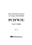
SERVICE
MANUAL
REVISION 0
JAN.1998
COPYRIGHT © 1998 CANON INC.
FY8-13F2-000
CANON PC400/420/430,FC200/220 REV.0 JAN.1998 PRINTED IN JAPAN (IMPRIME AU JAPON)
IMPORTANT
THIS DOCUMENTATION IS PUBLISHED BY CANON INC., JAPAN, TO SERVE AS A
SOURCE OF REFERENCE FOR WORK IN THE FIELD.
SPECIFICATIONS AND OTHER INFORMATION CONTAINED HEREIN MAY VARY
SLIGHTLY FROM ACTUAL MACHINE VALUES OR THOSE FOUND IN ADVERTISING AND
OTHER PRINTED MATTER.
ANY QUESTIONS REGARDING INFORMATION CONTAINED HEREIN SHOULD BE
DIRECTED TO THE COPIER SERVICE DEPARTMENT OF THE SALES COMPANY.
THIS DOCUMENTATION IS INTENDED FOR ALL SALES AREAS, AND MAY CONTAIN
INFORMATION NOT APPLICABLE TO CERTAIN AREAS.
COPYRIGHT © 1998 CANON INC.
Printed in Japan
Imprimé au Japon
Use of this manual should be strictly
supervised to avoid disclosure of
confidential information.
Prepared by
OFFICE IMAGING PRODUCTS TECHNICAL SUPPORT DEPARTMENT 1
OFFICE IMAGING PRODUCTS TECHNICAL SUPPORT DIVISION
CANON INC.
5-1, Hakusan 7-chome, Toride-shi, Ibaraki 302 Japan
COPYRIGHT © 1998 CANON INC.
CANON PC400/420/430,FC200/220 REV.0 JAN.1998 PRINTED IN JAPAN (IMPRIME AU JAPON)
INTRODUCTION
This Service Manual provides information needed to service the plain paper copiers
FC200/PC400(120V model), FC220/PC420(120V model), and PC430(LGL model) in
the field.
The FC200/PC400 differs from the FC220/PC420/PC430 for the following:
Model
Manual pick-up
Multifeeder
AE
FC220/PC420/PC430 Not available
Available
Available
FC200/PC400
Not available
Not available
Available
This Service Manual consists of the following chapters:
CHAPTER 1, “General Description,” introduces the copier’s features and specifications, shows how to operate the copier, and explains how copies are made.
CHAPTER 2, “Basic Operation,” provides outlines of the copier's various mechanical
workings.
CHAPTER 3, “Exposure System,” discusses the principles of operation used for the
copier's lens drive unit and scanner drive unit. It also explains the timing at which these
drive units are operated, and shows how they may be disassembled/assembled and
adjusted.
CHAPTER 4, “Image Formation System,” discusses the principles of how images
are formed. It also explains the timing at which the various units involved in image formation are operated, and shows how they may be disassembled/assembled and adjusted.
CHAPTER 5, “Pick-Up/Feeding System,” explains the principles used from when
copy paper is picked up to when a copy is delivered in view of the functions of electrical
and mechanical units and in relation to their timing of operation. It also shows how these
units may be disassembled/assembled and adjusted.
CHAPTER 6, “Fixing System,” explains the principles used to fuse toner images to
transfer media in view of the functions of electrical and mechanical units and in relation
to their timing of operation. It also shows how these units may be disassembled/assembled and adjusted.
CHAPTER 7, “Externals/Auxiliary Mechanisms,” shows the copier's external parts,
and explains the principles used for the copier's various control mechanisms in view of
the functions of electrical and mechanical units and in relation to their timing of operation. It also shows how these units may be disassembled/assembled and adjusted.
CHAPTER 8, “Installation,” introduces requirements for the site of installation, and
shows how the copier may be installed using step-by-step instructions.
CHAPTER 9, “Maintenance and Servicing,” provides tables of periodically replaced
parts and consumables/durables and scheduled servicing charts.
CHAPTER 10, “Troubleshooting,” provides tables of maintenance/inspection, standards/adjustments, and problem identification (image fault/malfunction).
Appendix contains a general timing chart and general circuit diagrams.
COPYRIGHT © 1998 CANON INC.
CANON PC400/420/430,FC200/220 REV.0 JAN.1998 PRINTED IN JAPAN (IMPRIME AU JAPON)
i
The following rules apply throughout this Service Manual:
1. Each chapter contains sections explaining the purpose of specific functions and
the relationship between electrical and mechanical systems with reference to the
timing of operation.
In the diagrams,
represents the path of mechanical drive
where a signal name accompanies the symbol
, the arrow indicates the direction of the
electric signal.
The expression "turn on the power" means flipping on the power switch, closing
the front door, and closing the delivery unit door, which results in supplying the
machine with power.
2. In the digital circuits, '1' is used to indicate that the voltage level of a given signal
is "High," while '0' is used to indicate "Low." (The voltage value, however, differs
from circuit to circuit.)
In practically all cases, the internal mechanisms of a microprocessor cannot be
checked in the field. Therefore, the operations of the microprocessors used in the
machines are not discussed: they are explained in terms of from sensors to the
input of the DC controller PCB and from the output of the DC controller PCB to
the loads.
Note:
The descriptions in this Service Manual are subject to change without notice for
product improvement or other purposes, and major changes will be communicated
in the form of Service Information bulletins.
All service persons are expected to have a good understanding of the contents of
this Service Manual and all relevant Service Information bulletins and be able to
identify and isolate faults in the machine.
ii
COPYRIGHT © 1998 CANON INC.
CANON PC400/420/430,FC200/220 REV.0 JAN.1998 PRINTED IN JAPAN (IMPRIME AU JAPON)
CONTENTS
CHAPTER 1 GENERAL DESCRIPTION
I. FEATURES ..................................1-1
II. SPECIFICATIONS .......................1-2
III. NAMES OF PARTS .....................1-4
A. External View ..........................1-4
B. Cross Section .........................1-5
IV. OPERATION ................................1-6
A. Control Panel ..........................1-6
1. PC420/430/FC220 .............1-6
2. PC400/FC200 ....................1-7
B. Making Copies ........................1-8
C. Jam Indicator.........................1-11
D. Add Paper Indicator ..............1-11
E. Replacing the Cartridge ........1-11
1.
Time to Replace the Cartridge
.........................................1-11
2. Replacing the Cartridge ...1-12
F. Changing the Density ...........1-14
G. Cleaning................................1-14
1. Copyboard Glass/Copyboard
Cover ...............................1-14
2. Lens Array .......................1-15
3. Pick-Up Roller..................1-16
H. When Not Using the Copier for a
Long Time .............................1-16
V. IMAGE FORMATION .................1-17
A. Outline.....................................1-17
CHAPTER 2 BASIC OPERATION
I.
BASIC OPERATION ....................2-1
A. Outline ....................................2-1
B. Outline of Electrical Circuit......2-2
C. Basic Sequence of Operations
(A4, 2 copies)..........................2-3
D. Main Motor Control Circuit ......2-5
1. Outline ...............................2-5
2. Operation ...........................2-5
3. Overcurrent Sensor ...........2-5
E. Inputs to DC Controller ...........2-6
1.
Inputs to DC Controller (1/2)
...........................................2-6
2. Inputs to DC Controller (2/2)
...........................................2-7
F. Outputs from DC Controller ....2-8
1. Outputs from DC Controller
(1/2) ...................................2-8
2. Outputs from DC Controller
(2/2) ...................................2-9
CHAPTER 3 EXPOSURE SYSTEM
I.
EXPOSURE/COPYBOARD DRIVE
SYSTEM ......................................3-1
A. Outline of Exposure System ...3-1
B. Copyboard Drive System........3-1
1. Outline ...............................3-1
2. Controlling the Copyboard
Drive ..................................3-3
3. Mechanism of Copyboard
Drive Assembly..................3-4
II. Controlling the Scanning Lamp....3-7
A. Outline ....................................3-7
B. Operations ..............................3-8
1. Turning the Scanning Lamp
COPYRIGHT © 1998 CANON INC.
ON and OFF ......................3-8
2. Controlling the Intensity of the
Scanning Lamp..................3-8
C. Controlling the Intensity of the
Scanning Lamp (VR604) ........3-8
III. MECHANICAL SYSTEM..............3-9
A. Scanning System..................3-10
1. Detaching the Scanning Lamp
Unit ..................................3-10
B. Copyboard Drive Assembly...3-11
1. Detaching the Copyboard
Drive Assembly ................3-11
CANON PC400/420/430,FC200/220 REV.0 JAN.1998 PRINTED IN JAPAN (IMPRIME AU JAPON)
iii
CHAPTER 4 IMAGE FORMATION SYSTEM
I.
PROCESS DESCRIPTION..........4-1
A. Outline ....................................4-1
B. Sequence of Image Formation
Operations (A4, 2 copies) .......4-2
C. Primary Charging Control Circuit
................................................4-3
1. Outline ...............................4-3
2. Operations .........................4-4
D. Controlling Developing Bias....4-6
1. Outline ...............................4-6
2. Operations .........................4-8
E. Transfer Charging Control Circuit
..............................................4-10
1. Outline .............................4-10
2. Operations .......................4-11
F. Document Density Measurement
(AE; PC420/430/FC220).......4-14
1.
2.
3.
Outline .............................4-14
Operations .......................4-14
Adjusting the AE Mechanism
(VR602, VR603) ..............4-15
II. CHARGING, DEVELOPING, AND
CLEANING SYSTEMS ..............4-17
A. Cartridge ...............................4-17
1. Outline .............................4-17
III. MECHANICAL SYSTEM............4-18
A. Photosensitive Drum.............4-19
1. Cleaning the Drum...........4-19
B. Transfer Charging Roller.......4-20
1. Cleaning the Transfer
Charging Roller................4-20
2. Detaching the Transfer
Charging Roller................4-20
CHAPTER 5 PICK-UP/FEEDING SYSTEM
I.
II.
OUTLINE .....................................5-1
CONTROLLING THE PICK-UP
ROLLER.......................................5-2
A. PC420/430/FC220 ..................5-2
B. PC400/FC200 .........................5-3
III. CONTROLLING THE
REGISTRATION ROLLER...........5-4
A. Outline ....................................5-4
B. Pick-Up/Feeding Timing Chart
(A4, 2 copies)..........................5-5
IV. CHECKING FOR JAMS...............5-6
A. Delivery Delay Jam .................5-6
1. PC420/430/FC220 .............5-6
2. PC400/FC200 ....................5-6
B. Delivery Stationary Jam..........5-7
1. PC420/430/FC220 .............5-7
2. PC400/FC200 ....................5-7
C. Pick-Up Delay Jam
(PC420/430/FC220)................5-8
D. Pick-Up Stationary Jam ..........5-9
1. PC420/430/FC220 .............5-9
2. PC400/FC200 ....................5-9
E. Paper is present at the pick-up or
delivery sensor at time of poweron or when the Copy Start key is
pressed. ..................................5-9
V. MECHANICAL SYSTEM............5-10
A. Pick-Up Roller Assembly.......5-11
1. Detaching the Pick-Up Roller
.........................................5-11
B. Registration Roller Assembly
..............................................5-14
1. Detaching the Registration
Roller Assembly...............5-14
C. Removing the Separation Pad
..............................................5-15
CHAPTER 6 FIXING SYSTEM
I.
iv
OUTLINE OF OPERATIONS .......6-1
A. Outline ....................................6-1
B. Controlling the Fixing Heater
Temperature............................6-3
COPYRIGHT © 1998 CANON INC.
C. Controlling the Supply Power to
the Fixing Heater ....................6-3
D. Protection Mechanisms ..........6-5
II. MECHANICAL SYSTEM..............6-6
A. Fixing Assembly......................6-7
CANON PC400/420/430,FC200/220 REV.0 JAN.1998 PRINTED IN JAPAN (IMPRIME AU JAPON)
1.
2.
Construction.......................6-7
Detaching the Fixing
Assembly ...........................6-7
3.
4.
Removing the Fixing Upper
Unit ....................................6-9
Detaching the Pressure Roller
.........................................6-11
CHAPTER 7 EXTERNALS/AUXILIARY MECHANISMS
I.
POWER SUPPLY ........................7-1
A. Outline ....................................7-1
B. Power Supply PCB .................7-2
C. Protection Mechanism for Power
Supply Circuit..........................7-2
II.MECHANICAL SYSTEM .................7-3
A. External Covers ......................7-4
1. Detaching the Control Panel
Cover .................................7-4
2. Detaching the Body Cover
...........................................7-5
3. Detaching the Top Cover
Assembly ...........................7-7
4. Detaching the Delivery
Assembly Cover.................7-7
5.
Detaching the Bottom Cover
...........................................7-8
B. Copyboard Assembly..............7-9
1. Detaching the Copyboard
Cover .................................7-9
2. Detaching the Copyboard ..7-9
C. DC Controller/DC Power Supply
PCB.......................................7-11
1. Detaching the DC
Controller/DC Power Supply
PCB..................................7-11
2. Points to Note When Installing
the Delivery Door Switch .7-13
D. Control Panel PCB................7-14
1. Detaching the Control Panel
PCB .................................7-14
CHAPTER 8 INSTALLATION
I.
II.
SELECTING THE SITE ...............8-1
UNPACKING AND INSTALLATION
.....................................................8-2
III. RELOCATING THE MACHINE ....8-5
CHAPTER 9 MAINTENANCE AND SERVICING
I.
PERIODICALLY REPLACED PARTS
.....................................................9-1
II. DURABLES..................................9-1
III. PERIODICAL SERVICING ..........9-1
IV. NOTES ABOUT CARTRIDGE .....9-2
A. Storing Sealed Cartridges.......9-2
B. Storing and Handling Unsealed
Cartridges ...............................9-3
1. Storing Unsealed Cartridges
...........................................9-3
2. Handling the Cartridge.......9-3
CHAPTER 10 TROUBLESHOOTING
I.
ADJUSTMENTS ........................10-5
A. Mechanical............................10-5
1. Image Leading Edge NonImage Width (position of white
paint on back of glass).....10-5
2. Image Leading Edge Margin
v
CANON PC400/420/430,FC200/220 REV.0 JAN.1998 PRINTED IN JAPAN (IMPRIME AU JAPON)
MAINTENANCE AND INSPECTION
...................................................10-3
A. Image Adjustment Basic
Procedure .............................10-3
B. Points to Note .......................10-4
II. STANDARDS AND
COPYRIGHT © 1998 CANON INC.
(cross feed direction). ....10-20
(point of detection for
13. The back of the copy is soiled.
registration)......................10-5
.......................................10-20
B. Electrical ...............................10-6
14. The copy has faulty fixing.
1. Adjusting the Intensity
.......................................10-21
(VR604) ...........................10-6
15. The copy has faulty leading
2. Adjusting the AE Mechanism
edge registration (blank area
(VR602, VR603) ..............10-8
much too wide). .............10-21
III. IMAGE TROUBLESHOOTING 10-11
16. The copy has faulty leading
A. Making Initial Checks ..........10-11
edge registration (blank area
1. Site Environment............10-11
too wide). .......................10-21
2. Checking the Documents
17. The copy has faulty leading
.......................................10-11
edge registration (no blank
3. Checking the Copyboard
area). .............................10-21
Cover and Copyboard Glass
18. The copy has a blurred image.
for Dirt and Scratches ....10-12
.......................................10-22
4. Checking the Lens Array for
19. The copy is foggy (cross feed
Dirt .................................10-12
direction). .......................10-22
5. Checking the Transfer
20. The copy has poor sharpness
Charging Roller..............10-12
(focus)............................10-22
6. Checking the Feeding
21. The copy is blank...........10-23
Assembly .......................10-12
22. The copy is solid black...10-23
7. Checking the Copy Paper
IV.
TROUBLESHOOTING
.......................................10-12
MALFUNCTIONS.....................10-24
8. Checking the Durables ..10-12
A. Troubleshooting Malfunctions
9. Others ............................10-14
............................................10-24
B. Samples of Image Faults ....10-16
1.
(self diagnosis;
C. Troubleshooting by Image Fault
PC400/FC200)...............10-24
............................................10-17
2. E0 ..................................10-24
1. The copy is too light (halftone
3. E2 ..................................10-25
areas only). ....................10-17
4. E6 ..................................10-25
2. The copy is too light (dark
5. E9 ..................................10-26
areas as well).................10-17
6. AC power is absent........10-26
3. The copy is too light
7. Pick-up fails. ..................10-27
(extremely light overall)..10-17
8. The scanning lamp fails to go
4. The copy has uneven density
ON. ................................10-27
(darker at front). .............10-18
9. The main motor fails to rotate.
5. The copy has uneven density
.......................................10-28
(lighter at front). .............10-18
10. The copyboard fails to move.
6. The copy is foggy (overall).
.......................................10-28
.......................................10-18
11.
(paper feeding normally)
7. The copy is foggy (paper feed
direction). .......................10-19
.......................................10-29
8. The copy has dark lines
12.
(at time of jam) ..........10-29
(paper feed direction,
13. The fixing heater fails to
relatively narrow). ..........10-19
operate...........................10-29
9. The copy has dark lines
V. TROUBLESHOOTING PAPER
(paper feed direction, thin).
FEED PROBLEMS ..................10-30
.......................................10-19
A. Copy Paper Jams ...............10-30
10. The copy has white spots
1. Pick-Up Assembly..........10-31
(paper feed direction).....10-19
2. Separation/Feeding Assembly
11. The copy has white lines
.......................................10-31
(paper feed direction).....10-19
3. Fixing/Delivery Assembly
12. The copy has white spots
.......................................10-32
vi
COPYRIGHT © 1998 CANON INC. CANON PC400/420/430,FC200/220 REV.0 JAN.1998 PRINTED IN JAPAN (IMPRIME AU JAPON)
B. Feeding Faults ....................10-33
1. Double Feeding .............10-33
2. Wrinkles .........................10-33
VI. FUNCTIONS AND ARRANGEMENT
OF ELECTRICAL PARTS ........10-34
A. Sensors and Solenoids.......10-34
B. Switches .............................10-35
C. Lamp, Heater, Motor, and Others
............................................10-36
D. Printed Circuit Board (PCB)10-37
E. Variable Resistors (VR) and
Check Pins by PCB ............10-38
1. DC Controller/DC Power
Supply PCB ...................10-38
2. Control Panel PCB.........10-39
VII. SELF DIAGNOSIS ...................10-40
APPENDIX
A. GENERAL TIMING CHART .........A-1
B. SIGNALS/ABBREVIATIONS LISTA-3
1. Signals....................................A-3
2. Abbreviations..........................A-4
COPYRIGHT © 1998 CANON INC.
C. GENERAL CIRCUIT DIAGRAM...A-5
D. SPECIAL TOOLS TABLE .............A-7
E. SOLVENTS/OILS TABLE .............A-8
CANON PC400/420/430,FC200/220 REV.0 JAN.1998 PRINTED IN JAPAN (IMPRIME AU JAPON)
vii
viii
COPYRIGHT © 1998 CANON INC.
CANON PC400/420/430,FC200/220 REV.0 JAN.1998 PRINTED IN JAPAN (IMPRIME AU JAPON)
CHAPTER 1
GENERAL DESCRIPTION
This chapter outlines the machine's specifications and how it may be operated.
I. FEATURES ..................................1-1
II. SPECIFICATIONS .......................1-2
III. NAMES OF PARTS .....................1-4
A. External View ..........................1-4
B. Cross Section .........................1-5
IV. OPERATION ................................1-6
A. Control Panel ..........................1-6
B. Making Copies ........................1-8
C. Jam Indicator.........................1-11
COPYRIGHT © 1998 CANON INC.
D.
E.
F.
G.
H.
Add Paper Indicator ..............1-11
Replacing the Cartridge ........1-11
Changing the Density ...........1-14
Cleaning................................1-14
When Not Using the Copier for a
Long Time .............................1-16
V. IMAGE FORMATION .................1-17
A. Outline.....................................1-17
CANON PC400/420/430,FC200/220 REV.0 JAN.1998 PRINTED IN JAPAN (IMPRIME AU JAPON)
1
CHAPTER 1 GENERAL DESCRIPTION
Blank Page
COPYRIGHT © 1998 CANON INC.
CANON PC400/420/430,FC200/220 REV.0 JAN.1998 PRINTED IN JAPAN (IMPRIME AU JAPON)
CHAPTER 1 GENERAL DESCRIPTION
I. FEATURES
1. Direct charging.
The charging roller directly charges paper, significantly reducing ozone emission.
2. Auto power-off.
The copier shuts off automatically when left alone for about 5 minutes after the last
copy operation.
3. Quick start.
The copier’s wait time is 0 second, always ready for quick copying work.
4. Cartridge type.
The core of the copier (photosensitive drum, toner case, charging roller, developing
assembly, and cleaning assembly) is integrated into a single cartridge. The user need
no more than replace the cartridge and perform simple cleaning to maintain the copier
in top condition.
5. Variety of copy effects.
In addition to black toner, the user has a choice of several colors. Taking advantage
of overlay copying, various copy effects may be obtained through mere replacement of
the cartridge.
6. Compact and light.
The copier is compact and light, providing good portability. It can easily substitute
as a personal copier.
7. Multifeeding (PC420/430/FC220).
A stack of copy paper may be placed on the pick-up tray. A press on the Copy Start
key is all it takes to generate multiple copies.
COPYRIGHT © 1998 CANON INC.
CANON PC400/420/430,FC200/220 REV.0 JAN.1998 PRINTED IN JAPAN (IMPRIME AU JAPON)
1-1
CHAPTER 1 GENERAL DESCRIPTION
II. SPECIFICATIONS
Performance
System
Type
Item
PC400/FC200
PC420/430/FC220
Body
Portable (w/ grips)
Copyboard
Moving
Light source
Tungsten lamp of fuse type
Lens
Lens array
Photosensitive medium
OPC (24 dia.)
Copying
Indirect electrostatic
Charging
Roller (direct charging)
Exposure
Slit (moving copyboard)
Copy density adjustment
Manual
Development
Dry
Pick-up
Manual tray
Separation
Curvature + Static eliminator
Cleaning
Blade
Fixing
Plane heater
Document type
Sheet, Book, 3-D object (2 kg/4.4 lb max.)
Maximum document size
LTR/A4; LGL*
Reproduction ratio
1:1 (±1.2%)
Wait time
0 sec (approx.; at 20°C/68°F)
First copy
22 sec (LTR)
Continuous copying
Not available
Copying speed
4 copies/min (approx.; A4R/LTR-R 4 copies/min (A4R/LTR-R or
or smaller)
smaller)
3 copies/min (LGL)
Copy size
A4/LTR; LGL* max.; postcard min.
Copy paper type
52 to 128 g/m2, Tracing paper, Colored paper, OHP film, Postcard
(vertical), Labels, Wrapping paper (63 g/m2)
Two-sided copying
• Same edge orientation.
• Copying on each side no more
than twice.
• Paper of 64 to 128 g/m2.
Overlay copying
• Paper of 64 to 128 g/m2.
• Copying on each side no more
than three times.
Automatic (AE) or Manual
Multifeeder
1 to 9 copies or F
Multifeeder tray
5 mm deep (about 50 sheets of
A4, 80 g/m2)
Copy tray
9 copies (approx.; A4/LTR, 80 g/m2)
Non-image width
2 mm (leading edge)
A4: 0 mm (left/right)
LTR/LGL: 2 mm (left/right)
Auto power-off
Available (5 min, approx.)
*PC430 only.
1-2
COPYRIGHT © 1998 CANON INC.
CANON PC400/420/430,FC200/220 REV.0 JAN.1998 PRINTED IN JAPAN (IMPRIME AU JAPON)
CHAPTER 1 GENERAL DESCRIPTION
Item
PC400/FC200
PC420/430/FC220
7.5° to 32.5°C/45.5° to 90.5°F
Temperature
Operating
5% to 85%
Humidity
environment
Atmospheric pressure 810.6 hPa to 1013.3 hPa (0.8 to 1 atm)
Serial numbers
120V, 60Hz
ZTG ✕✕✕✕✕ (PC400:WHITE)
ZTH ✕✕✕✕✕ (PC400:GRAY)
NVD
✕✕✕✕✕
(FC220:WHITE)
ZTJ
✕✕✕✕✕
(PC420:WHITE)
230V, 50Hz
RTL/PTQ
✕✕✕✕✕
(FC200:WHITE)
UTP/UTQ
RTM/PTR
✕✕✕✕✕ (FC220:WHITE)
PTS ✕✕✕✕✕ (FC220:WHITE)
PTT ✕✕✕✕✕ (FC220:WHITE)
Maximum
Power
Standby
consumption
Continuous
0.7 kW or less
Power
supply
Others
Serial numbers
Noise
0.1 W (approx.; 5 min; reference only)
0.2 kWh (reference only)
71 dB
Copying
Standby
Ozone
Sound power level
by ISO
0.01 ppm or less (average over 8 hr)
Width
14.1 in./359 mm
Dimensions Depth
15.7 in./402 mm
4.1 in./108 mm
Height
Weight (including cartridge) 16.6 lb/7.4 kg (approx.)
Consumables
Copy paper
Keep wrapped to protect against humidity.
Cartridge
See CHAPTER 9.
Specifications subject to change without notice.
COPYRIGHT © 1998 CANON INC.
CANON PC400/420/430,FC200/220 REV.0 JAN.1998 PRINTED IN JAPAN (IMPRIME AU JAPON)
1-3
CHAPTER 1 GENERAL DESCRIPTION
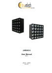
III. NAMES OF PARTS
A. External View
(PC420/430/FC220)
(PC400/FC200)
➀
➀
➂
➁
➁
➂
➃
➅
➆
➅
q
w
e
r
➄
➄
➃
t Delivery assembly cover
open/close button
y Delivery assembly cover
u Copy tray
Copyboard cover
Copyboard glass
Pick-up tray
Open/Close button
Figure 1-301A
➀
➁
➄
➃
➂
q
w
e
r
t
Upper cover
Pick-up guide
Density correction switch
Power switch
Cartridge
Figure 1-302A
1-4
COPYRIGHT © 1998 CANON INC.
CANON PC400/420/430,FC200/220 REV.0 JAN.1998 PRINTED IN JAPAN (IMPRIME AU JAPON)
CHAPTER 1 GENERAL DESCRIPTION
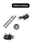
B. Cross Section
(PC420/430/FC220)
1
17
16
2
15 14
3
4
5
13
6
7
8
9
10
12 11
(PC400/FC200)
12
q
w
e
r
t
y
u
i
o
11
8
9
Copyboard cover
Copyboard glass
Cleaning assembly
Primary charging roller
Scanning lamp
Lens array
Developing cylinder
Registration roller
Pick-up roller
!0
!1
!2
!3
!4
!5
!6
!7
Pick-up tray
Transfer charging roller
Photosensitive drum
Fixing assembly
Delivery roller
Delivery tray
Heat exhaust fan
Delivery assembly cover
open/close button
Figure 1-301B
COPYRIGHT © 1998 CANON INC.
CANON PC400/420/430,FC200/220 REV.0 JAN.1998 PRINTED IN JAPAN (IMPRIME AU JAPON)
1-5
CHAPTER 1 GENERAL DESCRIPTION
IV. OPERATION
A. Control Panel
1. PC420/430/FC220
Error indications
: Check jam/Supply paper
: Jam
: Check error
: Check error
: Check error
and
and
and
3
9
ON OFF
6 5 4
lighter
q
w
e
r
t
1-6
1
darker
darker
C
AE A
lighter
2 4 5
6
7
8
10
Figure 1-401A
y Copy Count Set Key
Density Control Dial
• Each press on the key increases
AE key
the copy count (up to 9).
• Press it to select/deselect AE
(automatic exposure) mode.
• A press while ‘ ’ is displayed
AE Indicator
causes ‘ ’ to appear, indicating all
• ‘A’ goes ON when AE mode is
sheets on the pick-up tray will be
selected.
used for continuous copying.
• ‘A’ goes OFF when AE mode is
u Clear/Stop Key
deselected.
• During continuous copying, the key
Jam Indicator
serves as a Copy Stop key; the
• Flashes when paper jams inside
operation stops after finishing the
the copier.
ongoing copy.
Copy Count Indicator
• During standby, the key serves as a
• Displays the number of copies
Clear key, setting the copy count to
entered by pressing the Copy
‘ ’.
Count Set key.
i Copy Start Key
• The count decreases for each copy
o Power Switch
made; the initial number is
!0 Density Correction Switch
displayed after the last copy has
• Switches copy density among three
been made.
settings (top for darker, bottom for
• ‘ ’ is displayed to indicate pick-up
lighter).
failure or absence of paper; ‘ ’ is
• The density is switched by varying
the developing bias.
displayed in response to an error
found by self diagnosis.
COPYRIGHT © 1998 CANON INC.
CANON PC400/420/430,FC200/220 REV.0 JAN.1998 PRINTED IN JAPAN (IMPRIME AU JAPON)
CHAPTER 1 GENERAL DESCRIPTION
2. PC400/FC200
2
ON OFF
5
lighter
darker
1
3
4
Figure 1-402A
(right view)
q Density Control Lever
w Density Indicator
e Jam Indicator
• Flashes when paper jams inside
the copier.
• Goes and remains ON when an
error (self diagnosis) occurs in the
copier.
r Main Indicator
• Remains ON when copying is
ready.
t Power Switch
COPYRIGHT © 1998 CANON INC.
CANON PC400/420/430,FC200/220 REV.0 JAN.1998 PRINTED IN JAPAN (IMPRIME AU JAPON)
1-7
CHAPTER 1 GENERAL DESCRIPTION
B. Making Copies
1) Switch the copier ON.
• If necessary, wait until the intensity of the scanning lamp reaches the specified
value.
• The wait time is about 0 second.
• The copier will shut itself off in about 5 minutes if left alone without key operation.
2) Lift the copyboard cover, and place a document face down, along the size index.
• Place the document so that its center is at
on the size index (Figure 1-401B);
then, close the copyboard cover.
Document
Size index
Figure 1-401B
3) Adjust the copy density to suit the document.
4) Slide the pick-up guide to suit the size of copy paper.
5) Set copy paper on the pick-up tray.
PC420/430/FC220
Place a stack of copy paper of a size suited to the document on the pick-up tray;
make sure the edges of the sheets are flush.
• The stack may be 5 mm (about 50 sheets of plain paper).
Figure 1-402B
6) Set the copy count.
PC420/430/FC220
Set the number of copies to make (1 to 9 or F) using the + key, and check the Copy
Count indicator.
1-8
COPYRIGHT © 1998 CANON INC.
CANON PC400/420/430,FC200/220 REV.0 JAN.1998 PRINTED IN JAPAN (IMPRIME AU JAPON)
CHAPTER 1 GENERAL DESCRIPTION
7) Press the Copy Start key.
PC420/430/FC220
• To stop continuous copying, press the Clear/Stop key; the copier finishes the
ongoing copy and stops. The copy count displays the initial count.
Copying on OHP Film
• Set one sheet of film on the pick-up tray for each copy.
• Depending on the environment of the site, a press on the Copy Start key may not
pull the film inside the copier; if this is the case, perform the following:
1) Place copy paper under the film; stagger the sheet and film so that the leading edge
of the film is about 1 cm behind that of the paper.
1cm
Figure 1-403B
2) Hold the trailing edge of the copy paper, and set the sheet and film on the pick-up
tray.
3) While holding the trailing edge of the copy paper, press the Copy Start key.
Remove the paper when the film begins to move into the copier; the paper will no
longer serve its purpose.
Figure 1-404B
Note:
Take away each OHP film delivered to the copy tray.
COPYRIGHT © 1998 CANON INC.
CANON PC400/420/430,FC200/220 REV.0 JAN.1998 PRINTED IN JAPAN (IMPRIME AU JAPON)
1-9
CHAPTER 1 GENERAL DESCRIPTION
Manual Feeding
1)
2)
3)
4)
PC400/FC200
Set a document on the copyboard.
Adjust the Density Control lever to suit the document.
Slide the pick-up guide to suit the size of copy paper.
Insert copy paper along the pick-up guide.
• The copier starts copying operation automatically as soon as it detects paper.
• To continue copying, insert the next paper when the copyboard starts to return.
Making Two-Sided Copies
1) Turn over the copy while maintaining its feeding direction.
• Make sure that the paper is not moist or curled.
• Use paper of 64 to 128 g/m2 when making two-sided copies.
• Do not process each side more than twice.
Figure 1-405B
Making Overlay Copies
You can make two- or three-colored copies by replacing the cartridge.
• Use paper of 64 to 128 g/m2 when making overlay copies.
• Do not process each side more than three times.
1-10
COPYRIGHT © 1998 CANON INC.
CANON PC400/420/430,FC200/220 REV.0 JAN.1998 PRINTED IN JAPAN (IMPRIME AU JAPON)
CHAPTER 1 GENERAL DESCRIPTION
C. Jam Indicator
The Jam indicator starts to flash when paper jams inside the copier.
• Take care not to tear the paper when removing it; otherwise, be sure to remove all
pieces of paper.
1) Move the copyboard to the left until it stops.
2) Press the open/close button, and open the top cover.
3) Remove the jam.
• If the jam is in the pick-up or fixing assembly, hold the edge of the paper with both
hands, and pull it out slowly through the opening of the top cover.
• If the jam is in the delivery assembly, press the delivery assembly open/close
button to open the delivery cover; then, detach the paper from the delivery cover,
and pull it slowly in the direction of delivery.
4) Close the top cover and delivery cover; then, move the copyboard to the center.
• To resume copying, switch the copier ON, set the desired copy count, and set the
copy density.
D. Add Paper Indicator
PC420/430/FC220
‘ ’ flashes if you try to make a copy when the pick-up tray has run out of paper.
1) Check the pick-up tray for copy paper.
2) If no paper is on the tray, place paper.
If a stack of paper is on the tray, remove it first, then place it back after putting its
edges flush.
3) Press the Copy Start key.
• ‘ ’ goes OFF, and the remaining number of copies are made.
E. Replacing the Cartridge
1. Time to Replace the Cartridge
When the cartridge is running out of toner, copies tend to show white lines or vertical
white spots (Figure 1-401E).
Figure 1-401E
COPYRIGHT © 1998 CANON INC.
CANON PC400/420/430,FC200/220 REV.0 JAN.1998 PRINTED IN JAPAN (IMPRIME AU JAPON)
1-11
CHAPTER 1 GENERAL DESCRIPTION
If white lines or spots appear on copies, replace the cartridge as follows:
1) Remove the cartridge from the copier, and rotate it several times as shown in Figure
1-402E.
Figure 1-402E
2) Set the cartridge back in the copier, and make a copy.
a. If the output returns to normal,
• The cartridge may be used further; advise the user, however, to obtain a spare
cartridge.
b. If the output fails to return to normal,
• Replace the cartridge as described below.
2. Replacing the Cartridge
1) Move the copyboard to the left until it stops; then, press the open/close button to
open the top cover.
2) Slide the cartridge out of the copier.
3) Hold the cartridge with the Warning label facing up, and rotate it about 90 degrees in
both directions.
Figure 1-403E
1-12
COPYRIGHT © 1998 CANON INC.
CANON PC400/420/430,FC200/220 REV.0 JAN.1998 PRINTED IN JAPAN (IMPRIME AU JAPON)
CHAPTER 1 GENERAL DESCRIPTION
4) Detach the tip of the seal attached to the cartridge, and pull it straight out to the
front; about 50 cm.
Figure 1-404E
5) Hold the cartridge with its Warning label facing the left, and insert it in the copier with
care until it butts against the rear.
Figure 1-405E
6) Close the top cover, and return the copyboard to the center.
Note:
You can replace the black toner cartridge with any color cartridge the same way.
COPYRIGHT © 1998 CANON INC.
CANON PC400/420/430,FC200/220 REV.0 JAN.1998 PRINTED IN JAPAN (IMPRIME AU JAPON)
1-13
CHAPTER 1 GENERAL DESCRIPTION
F. Changing the Density
PC420/430/FC220
You have a choice of three settings for automatic density adjustment mode (AE);
switch the density if the copy is too dark or too light.
Density Correction Switch
Auto density
correction
Figure 1-401F
Note:
You can also switch the density among three settings in manual density adjustment
mode.
G. Cleaning
Advise the user to clean the following if the copies are soiled.
1. Copyboard Glass/Copyboard Cover
Wipe the part with a moist cloth; then, dry wipe it.
If dirt cannot be removed, wipe the part using mild detergent; then, dry wipe it.
1-14
COPYRIGHT © 1998 CANON INC.
CANON PC400/420/430,FC200/220 REV.0 JAN.1998 PRINTED IN JAPAN (IMPRIME AU JAPON)
CHAPTER 1 GENERAL DESCRIPTION
2. Lens Array
1) Move the copyboard to the left until it stops.
2) Put a cotton wad in the lens array groove, and move it back and forth lightly.
Fiber lens (face side)
Figure 1-401G
3)
4)
Open the upper cover, and remove the cartridge.
Put a flat-tipped cotton wad in the lens array (rear) groove, and move it back and
forth.
Figure 1-402G
COPYRIGHT © 1998 CANON INC.
CANON PC400/420/430,FC200/220 REV.0 JAN.1998 PRINTED IN JAPAN (IMPRIME AU JAPON)
1-15
CHAPTER 1 GENERAL DESCRIPTION
3. Pick-Up Roller
1) Open the top cover.
2) Dry wipe the pick-up roller while rotating it in pick-up direction with a cloth.
Note:
Do not make copies until the pick-up roller has completely dried.
Pick-up roller
Figure 1-403G
H. When Not Using the Copier for a Long Time
Advise the user to perform the following if she/he does not have any plan to use the
copier for a long time.
1) Disconnect the power plug.
2) Place the copier in a dust-free, sunlight-free place.
1-16
COPYRIGHT © 1998 CANON INC.
CANON PC400/420/430,FC200/220 REV.0 JAN.1998 PRINTED IN JAPAN (IMPRIME AU JAPON)
CHAPTER 1 GENERAL DESCRIPTION
V. IMAGE FORMATION
A. Outline
Copyboard glass
Lens array
Scanning lamp
Primary charging roller
Developing blade
Fixing film
Cleaning
blade
Developing
cylinder
Photosensitive drum
Transfer charging roller
Static eliminator
Pressure roller
Figure 1-501A
The copier is an indirect photorepro
graphic system constructed as shown in
Figure 1-501A.
The image formation process con
sists of seven steps as discussed below.
Step 1 : Primary charging (negative)
Step 2 : Image exposure
Step 3 : Development (AC and DC bias)
Step 4 : Transfer (negative)
Step 5 : Separation
Step 6 : Fixing
Step 7 : Drum cleaning
Latent static Image Formation
1. Primary charging
7. Drum cleaning
2. Image exposure
3. Development
4. Transfer
Delivery
6. Fixing
Multifeeder
Registration
5. Separation
: Flow of copy paper
: Rotation of drum
Figure 1-502A
The photosensitive drum has a layer
construction: the photoconductive layer
on the outside and the conductive alu
minum base, inside.
Photoconductive layer
Aluminum base
Figure 1-503A
COPYRIGHT © 1998 CANON INC.
CANON PC400/420/430,FC200/220 REV.0 JAN.1998 PRINTED IN JAPAN (IMPRIME AU JAPON)
1-17
CHAPTER 1 GENERAL DESCRIPTION
1-18
COPYRIGHT © 1998 CANON INC.
CANON PC400/420/430,FC200/220 REV.0 JAN.1998 PRINTED IN JAPAN (IMPRIME AU JAPON)
CHAPTER 2
BASIC OPERATION
This chapter outlines the machine's basic mechanisms and functions, relationship
between electrical and mechanical systems, and the timing of operation of respective
parts.
I.
BASIC OPERATION ....................2-1
A. Outline ....................................2-1
B. Outline of Electrical Circuit......2-2
C. Basic Sequence of Operations
(A4, 2 copies)..........................2-3
COPYRIGHT © 1998 CANON INC.
D. Main Motor Control Circuit ......2-5
E. Inputs to DC Controller ...........2-6
F. Outputs from DC Controller ....2-8
CANON PC400/420/430,FC200/220 REV.0 JAN.1998 PRINTED IN JAPAN (IMPRIME AU JAPON)
1
CHAPTER 2 BASIC OPERATION
Blank Page
COPYRIGHT © 1998 CANON INC.
CANON PC400/420/430,FC200/220 REV.0 JAN.1998 PRINTED IN JAPAN (IMPRIME AU JAPON)
CHAPTER 2 BASIC OPERATION
I. BASIC OPERATION
A. Outline
The copier can be divided into four functional blocks: pick-up/feeding, exposure,
image formation, and control blocks.
Control Block
Exposure Block
Control panel
Control circuit
Copyboard
Document
exposure
system
Optical path
Image Formation
Block
Primary charging roller
Drum
cleaning
Feeding
Photosensitive
drum
Transfer/
Separation
Copy tray
Fixing assembly/Delivery assembly
Developing
assembly
Pick-up
control
assembly
-up
Pick
tray
Pick-up/Feeding Block
Figure 2-101A
COPYRIGHT © 1998 CANON INC.
CANON PC400/420/430,FC200/220 REV.0 JAN.1998 PRINTED IN JAPAN (IMPRIME AU JAPON)
2-1
CHAPTER 2 BASIC OPERATION
B. Outline of Electrical Circuit
The copier’s main electrical mechanisms are controlled by the microprocessor on
the DC controller/DC power supply PCB. According to the program stored in advance,
the microprocessor reads input signals from the control keys, and generates signals to
drive such loads as motors, solenoids, and lamps, as necessary.
DC controller/DC power supply PCB
Copyboard position
sensor
Q
Delivery sensor
Pick-up sensor Photointerrupter
DC load
Microprocessor
TH1
Driver assembly
Fixing heater
temperature sensor
Scanning lamp
Main motor
Solenoid
Thermistor
Power switch
Control key
Primary/Transfer
charging roller
High-voltage
transformer
Developing
cylinder
Display
Q101
+DC24V +DC5V
+DC5V
Sub power
supply circuit
Door
switch
Delivery
door
switch
DC power
supply PCB
Heater
Relay
AC driver
Driver
AC load
Scanning lamp
Figure 2-101B
2-2
COPYRIGHT © 1998 CANON INC.
CANON PC400/420/430,FC200/220 REV.0 JAN.1998 PRINTED IN JAPAN (IMPRIME AU JAPON)
CHAPTER 2 BASIC OPERATION
C. Basic Sequence of Operations (A4, 2 copies)
Copy paper inserted (PC400/FC200)
Copy Start key ON
Copy paper inserted (PC400/FC200)
Power switch ON
Sequence
Copyboard
Main motor
1
(M1)
2
CBRV
STBY
INTR
CBRV STOP
CBFW
COPY
CBRV
CBFW
LSTR
STOP
STBY
2 sec
Scanning lamp
(LA1-LA8)
3 Primary AC
bias
4 Primary DC
bias
Transfer
5
charging
6
Copyboard drive
solenoid (SL2)
Pick-up
solenoid *
Registration
8
solenoid **
Registration
9
roller
Fixing heater
10
(H1)
7
*PC420/430/FC220
**PC400/FC200
Figure 2-101C
COPYRIGHT © 1998 CANON INC.
CANON PC400/420/430,FC200/220 REV.0 JAN.1998 PRINTED IN JAPAN (IMPRIME AU JAPON)
2-3
CHAPTER 2 BASIC OPERATION
Period
Description
Remarks
STBY
(Standby)
Between when the copier
is switched ON and when
the Copy Start key is
pressed.
Between when LSTR is
over and when the Copy
Start key is pressed.
Waits for a press on the
Copy Start key.
INTR
(Initial Rotation)
For about 6 sec after STBY
is over.
Executes pick-up.
Removes residual charge
from the photosensitive
drum and stabilizes the drum
sensitivity in preparation for
copying operation.
The copyboard
moves from the
home position to
the start position.
CBFW
(Copyboard
Forward)
While the copyboard is
moving forward (about 10
sec).
The scanning lamp illuminates the document, and the
reflected optical image is
projected to the photosensitive drum through the
lens array.
The copy paper
is moved to the
transfer
assembly.
CBRV
(Copyboard
Reverse)
While the copyboard is
moving in reverse (about 4
sec).
Returns the copyboard to the
start position in preparation
for the next copy; if last
copy, the copyboard is
returned to the home
position.
In continuous
copying, the pickup signal is generated for pick-up
operation.
After CBRV for the last
copy is over until 3 sec
after the copy paper has
moved past the delivery
sensor.
Discharges the last copy.
COPY
LSTR
(Last Rotation)
Table 2-101C
2-4
COPYRIGHT © 1998 CANON INC.
CANON PC400/420/430,FC200/220 REV.0 JAN.1998 PRINTED IN JAPAN (IMPRIME AU JAPON)
CHAPTER 2 BASIC OPERATION
D. Main Motor Control Circuit
1. Outline
Figure 2-101D shows the circuit that controls the main motor (M1), and the circuit
has the following functions:
a.
b.
turns the main motor ON and OFF.
controls the main motor speed (constant)
The main motor (M1) is a DC motor and is equipped with a motor rotation sensor
(Q901) to serve as a clock pulse generator. Clock pulses (MMCLK) corresponding to
the revolution of the motor are generated while the motor is rotating. The speed control
circuit controls the speed of the motor with reference to these clock pulses.
2. Operation
The drive circuit on the DC controller/DC power supply PCB causes the main motor
drive command (MMD) to go ‘0’ in response to instructions from the microprocessor,
thereby causing the main motor to rotate at a specific speed.
3. Overcurrent Sensor
When the overcurrent sensor circuit detects an overload in the main motor (M1), the
speed controller circuit exerts control so that the rotation of the motor is slowed down.
If the revolution of the main motor falls below a specific revolution, however, an error
associated with ‘E2’ can occur.
+24V
Drive circuit
Speed control circuit
Microprocessor (Q101)
Overcurrent
detection
circuit
J201
-5
(+)
Main motor drive
-4 command (MMD) (-)
M1
Main motor
Q901
Motor rotation detection PCB
Main motor clock pulse
-1 signal (MMCLK)
Q101
DC controller/DC power supply PCB
Figure 2-101D
COPYRIGHT © 1998 CANON INC.
CANON PC400/420/430,FC200/220 REV.0 JAN.1998 PRINTED IN JAPAN (IMPRIME AU JAPON)
2-5
CHAPTER 2 BASIC OPERATION
E. Inputs to DC Controller
1. Inputs to DC Controller (1/2)
DC controller/DC power supply PCB
Door switch
SW1
Delivery door switch
SW2
J104
AC power
supply
Density
correction
switch
(PC420/430/
FC220)
J103
0 1 2
SW606
(bottom: lightens)
J601
-20(-15)
J601
-2
J601
-1
J202
-3
DGT 2 Oscillation signal (output)
J202
-21
Press on any key or density
KEYR 2
J202
correction switch allows input
-22
of oscillation signal.
KEYR 3
(PC420/430/FC220 only)
SW601
( )
SW602
(+ )
J601
-19
J202
-4
SW603
(C/S)
J601
-15
J202
-8
J601
-14(-10)
J202
-9(-8)
(top: darkens)
DGT 0
DGT 1
Oscillation signal (output;
PC420/430/FC220 only)
SW605
(AE)
Power switch
SW604
+5V
Density
adjustment
dial/lever
+5V
VR601
J601
-21(-16)
J601-13(-8)
J601-22(-17)
PWSON
When ‘0’, power switch goes ON.
5V
J202
-2
J202-10
J202-1
Turning density adjustment dial varies
voltage. (turn to darken brings it closer to 0V)
Control panel PCB
Note: The pin No. in parentheses refers
to the PC400/FC200.
Figure 2-101E
2-6
COPYRIGHT © 1998 CANON INC.
CANON PC400/420/430,FC200/220 REV.0 JAN.1998 PRINTED IN JAPAN (IMPRIME AU JAPON)
CHAPTER 2 BASIC OPERATION
2. Inputs to DC Controller (2/2)
DC controller/DC power supply PCB
Delivery detection PCB
Delivery detection
J801
J603
Fixing heater
surface
temperature
detection
Q801
-3
-3
-1
-5
-2
-4
J603
-1
J601
-15(-10)
J202
-8
J601
-12(-7)
J202
-11
J601
-11(-6)
J202
-12
J601
J202
DGT1
Oscillation signal (output)
KEYR0
When Q801 detects copy paper,
oscillation signal (DGT1) is input.
TH1
When surface temperature of fixing
heater increases, voltage lowers.
TH1
-2
J621
PD601
PD602
See Chap.4.
AE sensor/
intensity sensor
Copyboard
position
detection
Control panel PCB
J201
-11
J905
-2
Q902
-10
-12
-3
-1
Copyboard position detection PCB
Motor rotation
detection
DGTO
Oscillation signal (output)
When Q902 detects copyboard
KEYRO start position or reversal position,
oscillation signal (DGT0) is input.
+5V
J904
-2
-2
-3
-1
-1
-3
Q901
Motor rotation detection PCB
Pick-up
detection
MMCLK Clock pulses corresponding to
revolution of main motor are
generated.
DGT2
Q131
Oscillation signal
(output)
KEYR0 When Q131 detects
copy paper, oscillation
signal (DGT2) is input.
Note: The pin No. in parentheses refers to
the PC400/FC200.
Figure 2-102E
COPYRIGHT © 1998 CANON INC.
CANON PC400/420/430,FC200/220 REV.0 JAN.1998 PRINTED IN JAPAN (IMPRIME AU JAPON)
2-7
CHAPTER 2 BASIC OPERATION
F. Outputs from DC Controller
1. Outputs from DC Controller (1/2)
DC controller/DC power supply PCB
Thermal fuse 2
FU2
J101
H1
See Chap.6.
J102
Fixing heater
LA1 to LA8
Scanning
lamp
J906
-1
Thermal fuse 1
J108
FU1
-1
-2
See Chap.3.
-2
Lamp PCB
+24V
J903
-1
Main motor M1 -2
J201
-5
-4
MMD When ‘0’, main motor goes ON.
High voltage
output
See Chap.4.
Figure 2-101F
2-8
COPYRIGHT © 1998 CANON INC.
CANON PC400/420/430,FC200/220 REV.0 JAN.1998 PRINTED IN JAPAN (IMPRIME AU JAPON)
CHAPTER 2 BASIC OPERATION
2. Outputs from DC Controller (2/2)
a.
PC420/430/FC220
DC controller/DC power supply PCB
Pick-up
solenoid
Copyboard
drive
solenoid
J901
-1
SL1
-2
J902
-1
SL2
-2
J201 +24V
-7
-6
PUSD When ‘0’, SL1 goes ON.
J101 +24V
-9
-8
CBSD When ‘0’, SL2 goes ON.
(voltage to SL2 is switched
between 24V and 15V to
ensure stable operation)
Figure 2-102F
b.
PC400/FC200
DC controller/DC power supply PCB
Registration
solenoid
Copyboard
drive
solenoid
J901
-1
SL1
-2
J902
-1
SL2
-2
J201 +24V
-7
-6
RGSD When ‘0’, SL1 goes ON.
J101 +24V
-9
-8
CBSD When ‘0’, SL2 goes ON.
(voltage to SL2 is switched
between 24V and 15V to
ensure stable operation)
Figure 2-103F
COPYRIGHT © 1998 CANON INC.
CANON PC400/420/430,FC200/220 REV.0 JAN.1998 PRINTED IN JAPAN (IMPRIME AU JAPON)
2-9
CHAPTER 2 BASIC OPERATION
2-10
COPYRIGHT © 1998 CANON INC.
CANON PC400/420/430,FC200/220 REV.0 JAN.1998 PRINTED IN JAPAN (IMPRIME AU JAPON)
CHAPTER 3
EXPOSURE SYSTEM
This chapter outlines the machine's copyboard drive and scanning lamp control
systems in relation to mechanisms and functions, relationship between electrical and
mechanical systems, and the timing of operation of respective parts.
I.
EXPOSURE/COPYBOARD DRIVE
SYSTEM ......................................3-1
A. Outline of Exposure System ...3-1
B. Copyboard Drive System........3-1
II. Controlling the Scanning Lamp....3-7
A. Outline ....................................3-7
COPYRIGHT © 1998 CANON INC.
B. Operations ..............................3-8
C. Controlling the Intensity of the
Scanning Lamp (VR604) ........3-8
III. MECHANICAL SYSTEM..............3-9
A. Scanning System..................3-10
B. Copyboard Drive Assembly...3-11
CANON PC400/420/430,FC200/220 REV.0 JAN.1998 PRINTED IN JAPAN (IMPRIME AU JAPON)
1
CHAPTER 3 EXPOSURE SYSTEM
Blank Page
COPYRIGHT © 1998 CANON INC.
CANON PC400/420/430,FC200/220 REV.0 JAN.1998 PRINTED IN JAPAN (IMPRIME AU JAPON)
CHAPTER 3 EXPOSURE SYSTEM
I. EXPOSURE/COPYBOARD DRIVE SYSTEM
A. Outline of Exposure System
While the copyboard is moving forward, the scanning lamp (LA1 through LA8)
illuminates the document, and the reflected light is projected to the photosensitive drum
through the lens array.
Copyboard glass
Scanning lamp
Lens array
Photosensitive
drum
Figure 3-101A
B. Copyboard Drive System
1. Outline
The copyboard is moved forward or in reverse by transmitting the drive of the main
motor (M1) to the copyboard drive gear (pinion). Figure 3-101B illustrates the
movement of the copyboard.
1
Copyboard Home 2
Position (HP)
3
Copyboard Start
Position (SP)
4
Copyboard Reversal
Position
5
Home
Position
Copyboard
Reverse
Forward
Reverse
Stop
Copier
Continuous copying
Figure 3-101B Front View
COPYRIGHT © 1998 CANON INC.
CANON PC400/420/430,FC200/220 REV.0 JAN.1998 PRINTED IN JAPAN (IMPRIME AU JAPON)
3-1
CHAPTER 3 EXPOSURE SYSTEM
Copyboard position sensor (Q902)
Forward
Description
Copyboard position (cams)
Reverse
• Copyboard is at the home
position.
• Copyboard solenoid goes
ON in response to a press
on the Copy Start key or
insertion of copy paper.
Reversal cam Registration cam
Start position cam
Reverse
Copyboard
position sensor
lever
Copyboard position sensor (Q902): OFF
(front view)
• Copyboard is at the start
position.
• Copyboard drive solenoid
goes OFF.
• Scanning lamp ON.
• The copyboard drive
solenoid goes ON about
0.5 second after the Copy
Start key is pressed.
• AE measurement starts.
• Registration roller goes
ON (by registration cam).
• Copyboard is at the reversal
position.
• Copyboard drive solenoid
goes OFF.
• After a specific period,
copyboard drive solenoid
goes ON.
• Pick-up solenoid goes ON
(continuous copying).
• Scanning lamp OFF.
Forward
Q902:OFF
Continuous copying
Q902:ON
Q902:ON ➞ OFF
• For the last copy, the copy
board drive solenoid goes
OFF at the copyboard
home position.
Q902:ON ➞ OFF
Table 3-101B
3-2
COPYRIGHT © 1998 CANON INC.
CANON PC400/420/430,FC200/220 REV.0 JAN.1998 PRINTED IN JAPAN (IMPRIME AU JAPON)
CHAPTER 3 EXPOSURE SYSTEM
2. Controlling the Copyboard Drive
The copyboard is controlled for forward, reverse, and stop operations by the
copyboard drive solenoid (SL2) and forward/ reverse switching mechanism.
A photosensor (Q902) is provided on the copyboard drive assembly to monitor the
position of the copyboard; as the copyboard moves, the cam found under the copyboard
pushes the copyboard sensor lever to turn the photosensor ON or OFF.
‘E2’ is displayed if the copyboard fails to complete its movement within a specific
period of time.
In response to the signal from Q902, the DC controller controls the timing for paper
transport and the movement (forward, reverse, stop) of the copyboard; see Table 3101B.
Start position cam
Registration cam
Rack
Copyboard position sensor lever
Forward
Copyboard position sensor signal
Copyboard position sensor
Q902
Copyboard glass
Reversal cam
J201 Copyboard drive gear
-10
Copyboard drive solenoid drive command
J201
-9
DC controller/
DC power
supply PCB
(CBSD)
Copyboard drive
solenoid
SL2
Forward Forward/Reverse
Reverse
gear switching mechanism gear
J201
-4
Main motor drive command (MMD)
M1
Main motor
Figure 3-102B Front View
COPYRIGHT © 1998 CANON INC.
CANON PC400/420/430,FC200/220 REV.0 JAN.1998 PRINTED IN JAPAN (IMPRIME AU JAPON)
3-3
CHAPTER 3 EXPOSURE SYSTEM
3. Mechanism of Copyboard Drive Assembly
The forward gear and reverse gear are rotating in the direction of the arrow (Figure
103B) while the main motor (M1) is operating.
The forward/reverse switching mechanism engages with either the forward gear or
the reverse gear depending on the orientation of the copyboard position sensor lever
and the state (ON/OFF) of the copyboard drive solenoid (SL2) operated by the start
position cam or reversal cam; when not engaged, the mechanism is said to be free, and
the copyboard can be moved by hand.
The above mechanism is used to move the copyboard forward and reverse or to
stop it.
Copyboard (rack)
Forward/Reverse switching mechanism
Forward
Reversing gear
Start position cam
Copyboard position lever
Copyboard drive gear (pinion)
Forward gear
Reverse
Main motor gear
Reversing cam
Copyboard drive
solenoid (SL2)
M1
Main motor
Figure 3-103B
Copyboard position
sensor lever
Copyboard drive
solenoid (SL2)
ON
OFF
Down
Up
forward
reverse
stop (free)
Note:
i. The direction (forward/reverse) is switched when the copyboard drive solenoid
is OFF.
ii. The direction of the drive is maintained while the copyboard drive solenoid is
ON.
Table 3-102B
3-4
COPYRIGHT © 1998 CANON INC.
CANON PC400/420/430,FC200/220 REV.0 JAN.1998 PRINTED IN JAPAN (IMPRIME AU JAPON)
CHAPTER 3 EXPOSURE SYSTEM
a.
Stopping the Copyboard
Causing the copyboard drive solenoid (SL2) to go OFF frees both forward and
reverse gears so that the copyboard remains stationary.
At the time, the copyboard may be moved to the right or left by hand.
b.
Moving the Copyboard in Reverse
When SL2 goes ON while the main motor is operating, the forward/reverse
switching mechanism engages with the reverse gear, and the reverse gear rotates in
the direction of the arrow, causing the copyboard to move in reverse.
The copyboard moves in reverse about two times as fast as when it moves forward
owing to the difference in the gear ratio.
Copyboard
drive gear
Reversing gear
Forward/Reverse
switching
mechanism
M1
Reverse
Main motor
Copyboard drive
solenoid (SL2)
Figure 3-104B
COPYRIGHT © 1998 CANON INC.
CANON PC400/420/430,FC200/220 REV.0 JAN.1998 PRINTED IN JAPAN (IMPRIME AU JAPON)
3-5
CHAPTER 3 EXPOSURE SYSTEM
c.
Moving the Copyboard Forward
When the copyboard has moved in reverse and is positioned as shown in Figure 3105B, the start position cam pushes down the copyboard position sensor lever. When
SL2 goes ON in this position, the forward/reverse switching mechanism moves to the
position shown in the figure, causing the forward/reverse switching mechanism to
engage with the forward gear; as a result, the forward gear rotates in the direction of the
arrow, moving the copyboard forward.
Copyboard
drive gear
Forward gear
Forward
Forward/Reversal
switching
mechanism
Start position
cam
M1
Main motor
Copyboard drive solenoid (SL2)
Figure 3-105B
3-6
COPYRIGHT © 1998 CANON INC.
CANON PC400/420/430,FC200/220 REV.0 JAN.1998 PRINTED IN JAPAN (IMPRIME AU JAPON)
CHAPTER 3 EXPOSURE SYSTEM
II. Controlling the Scanning Lamp
A. Outline
Figure 3-201A shows the circuit that controls the scanning lamp (fuse lamp), and the
circuit has the following functions:
• Turns the scanning lamp ON and OFF.
• Controls the intensity of the scanning lamp.
An intensity sensor (PD601) is provided to ensure that the original will be illuminated
after the intensity of the scanning lamp has stabilized.
The intensity of the scanning lamp is checked by the lamp intensity detection signal
(LID) to make sure that the intensity has reached the specified value.
In addition, a rush current protection circuit is provided to prevent rush current
occurring when the lamp turns on.
Scanning lamp
(LA1-LA8) J108-1
+24VU
J621
-4
Q143
-
Intensity sensor
-3 (PD601)
(-1)
+
Rush current
protection circuit
J108-2
Lamp
driver
circuit
VR604
J601
-10
(-5)
+
J202
-13
Lamp intensity sensor signal (LID)
5V
Microprocessor
Lamp ON
signal
(LAPWM)
Amplifier circuit
Control panel PCB
DC controller/DC power supply PCB
The number within parentheses represents the PC400/FC200.
FIgure 3-201A
COPYRIGHT © 1998 CANON INC.
CANON PC400/420/430,FC200/220 REV.0 JAN.1998 PRINTED IN JAPAN (IMPRIME AU JAPON)
3-7
CHAPTER 3 EXPOSURE SYSTEM
B. Operations
1. Turning the Scanning Lamp ON and OFF
• Square waves of the LAPWM command corresponding to the output of the amplifi
er circuit are generated to the lamp driver circuit. (Q143 ON)
Current flows into the filament of the lamp, causing the fluorescent lamp to go
ON at high frequency.
2. Controlling the Intensity of the Scanning Lamp
• If the intensity of the lamp is low when the lamp goes ON,
Initial power of the intensity sensor PD601 is low.
Output voltage of the amplifier circuit is high.
Duty ratio (H) of the output of the microprocessor (LAPWM com
mand) grows high.
Current flowing to the lamp increases.
• If the intensity of the lamp is high when the lamp goes ON,
Initial power of the intensity sensor PD601 is high.
Output voltage of the amplifier circuit is low.
Duty ratio (H) of the output of the microprocessor (LAPWM com
mand) grows low.
Current flowing to the lamp decreases.
• If the microprocessor finds out that the scanning lamp has remained on for 2 min
at such times as not prescribed, it activates the self diagnostic mechanism; the
results are indicated by ‘E6’ for the PC420/430/FC220 and ‘JAM’ for the
PC400/FC200.
C. Controlling the Intensity of the Scanning Lamp (VR604)
You must adjust the intensity of the lamp if you have replaced the scanning lamp
unit, intensity sensor or control panel PCB; see p.10-6.
Note:
You must adjust the AE mechanism after adjusting the intensity.
(PC420/430/FC220)
3-8
COPYRIGHT © 1998 CANON INC.
CANON PC400/420/430,FC200/220 REV.0 JAN.1998 PRINTED IN JAPAN (IMPRIME AU JAPON)
CHAPTER 3 EXPOSURE SYSTEM
III.MECHANICAL SYSTEM
Here, the copier is discussed in terms of its mechanical characteristics and
operation and how to disassemble and assemble it.
Be sure to observe the following for disassembly/assembly work:
1. ! Disconnect the power cord for safety before disassembly or reassembly
work.
2. Unless otherwise noted, reassembly is the reverse of disassembly.
3. Group the screws by type (length and diameter) and location.
4. One of the mounting screws used on the rear cover is provided with a washer to
protect against static electricity. Be sure to keep the washer with the screw when
mounting the cover.
5. The fixing screw for the grounding wire and varistors is fitted with a washer to
ensure electric continuity; be sure to use the washer for reassembly.
6. If possible, avoid operating the machine with any of its parts removed.
COPYRIGHT © 1998 CANON INC.
CANON PC400/420/430,FC200/220 REV.0 JAN.1998 PRINTED IN JAPAN (IMPRIME AU JAPON)
3-9
CHAPTER 3 EXPOSURE SYSTEM
A. Scanning System
➁
disengage
➁
1. Detaching the Scanning Lamp Unit
1) Detach the top cover assembly.
2) Disengage the two hooks q and pins
w, and detach the lamp unit e.
➀
Figure 3-301A
Caution:
The scanning lamp is adjusted at
the factory with high precision to
ensure the best intensity of light; if
necessary, replace it as part of the
scanning lamp unit; see Figure 3302A.
Scanning lamp unit
Figure 3-302A
3-10
COPYRIGHT © 1998 CANON INC.
CANON PC400/420/430,FC200/220 REV.0 JAN.1998 PRINTED IN JAPAN (IMPRIME AU JAPON)
CHAPTER 3 EXPOSURE SYSTEM
B. Copyboard Drive Assembly
➁
1. Detaching the Copyboard Drive
Assembly
1) Take out the fixing assembly.
2) Remove the screw and remove the
grounding wire q; remove the screw,
and remove the motor rotation
detecting PCB w; then, disconnect
the four connectors e.
➂
➀
➂
Figure 3-301B (rear view)
3) Remove the screw r, and detach
the cartridge support t.
➃
➄
(rear)
Figure 3-302B
Note:
Take extra care not to damage the
teeth of the gear when lifting the
copyboard drive assembly.
COPYRIGHT © 1998 CANON INC.
CANON PC400/420/430,FC200/220 REV.0 JAN.1998 PRINTED IN JAPAN (IMPRIME AU JAPON)
3-11
CHAPTER 3 EXPOSURE SYSTEM
4) Remove the four screws (t, M4X8,
yellow; y, M3X6, white), and detach
the copyboard drive assembly u as
if to lift it.
➄
➆
➅
➄
Figure 3-303B
3-12
COPYRIGHT © 1998 CANON INC.
CANON PC400/420/430,FC200/220 REV.0 JAN.1998 PRINTED IN JAPAN (IMPRIME AU JAPON)
CHAPTER 4
IMAGE FORMATION SYSTEM
This chapter outlines the machine's image formation system in relation to
mechanisms and functions, relationship between electrical and mechanical systems,and
the timing of operation of respective parts.
I.
PROCESS DESCRIPTION..........4-1
A. Outline ....................................4-1
B. Sequence of Image Formation
Operations (A4, 2 copies) .......4-2
C. Primary Charging Control Circuit
................................................4-3
D. Controlling Developing Bias....4-6
E. Transfer Charging Control Circuit
..............................................4-10
COPYRIGHT © 1998 CANON INC.
F.
Document Density Measurement
(AE; PC420/430/FC220).......4-14
II. CHARGING, DEVELOPING, AND
CLEANING SYSTEMS ..............4-17
A. Cartridge ...............................4-17
III. MECHANICAL SYSTEM............4-18
A. Photosensitive Drum.............4-19
B. Transfer Charging Roller.......4-20
CANON PC400/420/430,FC200/220 REV.0 JAN.1998 PRINTED IN JAPAN (IMPRIME AU JAPON)
1
CHPTER 4 IMAGE FORMATION SYSTEM
Blank Page
COPYRIGHT © 1998 CANON INC.
CANON PC400/420/430,FC200/220 REV.0 JAN.1998 PRINTED IN JAPAN (IMPRIME AU JAPON)
CHPTER 4 IMAGE FORMATION SYSTEM
I. PROCESS DESCRIPTION
A. Outline
The copier’s image formation system has the following functions:
Controls the scanning lamp.
Controls the primary charging.
Controls the transfer charging.
Controls the developing bias.
Lamp intensity sensor
Scanning
lamp
Lens
array
AE sensor
Developing
cylinder
-19
Photosensitive
drum
Transfer charging high voltage
J202-13
-4
AE signal (AE)
J601-10
Lamp intensity sensor
signal (LID)
Control panel
PCB
Primary corona high voltage
-2
Lamp ON command (LAPWM)
J621-4
Static eliminator
Primary
charging
roller
Transfer
charging
roller
Developing bias
•
•
•
•
DC controller/DC power supply PCB
Note : The AE sensor is provided for the PC420/430/FC220 only.
Figure 4-101A
COPYRIGHT © 1998 CANON INC.
CANON PC400/420/430,FC200/220 REV.0 JAN.1998 PRINTED IN JAPAN (IMPRIME AU JAPON)
4-1
CHPTER 4 IMAGE FORMATION SYSTEM
B. Sequence of Image Formation Operations (A4, 2 copies)
Copy paper inserted (PC400/FC200)
Copy Start key ON
Copy paper inserted (PC400/FC200)
Power switch ON
Sequence
Copyboard
Main motor
1
(M1)
Scanning lamp
2
(LA1-LA8)
CBRV
STBY
INTR
CBRVSTOP
CBFW
COPY
CBRV
CBFW
LSTR
STOP
STBY
3 Primary AC bias
4 Primary DC bias
5 Transfer charging
4 sec
1.5 sec
6 Developing
AC bias
Developing
7
DC bias
Scanning lamp
: Cleaning mode
: ON
Transfer
charging
: -230V
Primary DC bias
: -625V
: Measurement mode
: Transfer
: -400V
Developing DC bias
: -120V to -560V
(variable according to
density control dial/
lever, AE)
Figure 4-401B
4-2
COPYRIGHT © 1998 CANON INC.
CANON PC400/420/430,FC200/220 REV.0 JAN.1998 PRINTED IN JAPAN (IMPRIME AU JAPON)
CHPTER 4 IMAGE FORMATION SYSTEM
C. Primary Charging Control Circuit
1. Outline
Figure 4-101C shows the circuit that controls the primary charging, and the circuit
has the following functions:
• Turns the DC bias ON and OFF.
• Turns the AC bias ON and OFF.
• Controls the DC bias voltage
(constant).
• Controls the AC bias current
(constant).
A DC bias (-625 V/-230 V) and an AC bias are applied to the primary charging roller
to maintain the surface potential of the photosensitive drum uniform.
During document exposure (-625 V) and non-exposure periods (-230 V) DC bias is
switched by the DC bias high output command (HVPHO).
The DC bias and AC bias are turned ON and OFF by the DC bias ON command
(HVPDC) and AC bias ON command (HVPAC), respectively.
Reference:
Unless the document is being illuminated, the DC bias is switched to -230V to
prevent adhesion of toner on the photosensitive drum.
COPYRIGHT © 1998 CANON INC.
CANON PC400/420/430,FC200/220 REV.0 JAN.1998 PRINTED IN JAPAN (IMPRIME AU JAPON)
4-3
CHPTER 4 IMAGE FORMATION SYSTEM
2. Operations
a. HVPDC=1, HVPHO=1 (copying)
DC bias control circuit set to ‘-625 V’.
Transformer T106 generates ‘DC bias’.
HVPAC=1
Oscillation control circuit goes ON.
Transformer T103 generates AC bias
Primary charging
(DC bias + AC bias) goes ON.
b.
HVPDC=1, HVPHO=0 (document not exposed)
DC bias control circuit set to ‘-240 V’.
Transformer T106 generates DC bias.
HVPAC=1
Oscillation control circuit goes ON.
Transformer T103 generates AC bias.
Primary charging
(DC bias + AC bias) goes ON.
c.
HVPDC=0, HVPHO=0 (standby)
DC bias control circuit goes OFF.
Transformer T106 DC bias goes OFF.
HVPAC=0
Oscillation control circuit goes OFF.
Transformer T103 goes OFF.
Primary charging
(DC bias + AC bias) goes OFF.
4-4
COPYRIGHT © 1998 CANON INC.
CANON PC400/420/430,FC200/220 REV.0 JAN.1998 PRINTED IN JAPAN (IMPRIME AU JAPON)
CHPTER 4 IMAGE FORMATION SYSTEM
J6
Primary
charging
roller
Photosensitive
drum
Amplifier
Oscillation
control circuit
Oscillation
circuit
AC bias ON command
(HVPAC)
DC bias high output
command (HVPHO)
DC bias ON command
(HVPDC)
DC bias
control circuit
Transformer
(T103)
Current detection
DC current detection
Transformer
(T106)
Microprocessor
DC controller/DC power supply PCB
Figure 4-101C
COPYRIGHT © 1998 CANON INC.
CANON PC400/420/430,FC200/220 REV.0 JAN.1998 PRINTED IN JAPAN (IMPRIME AU JAPON)
4-5
CHPTER 4 IMAGE FORMATION SYSTEM
D.
Controlling Developing Bias
1. Outline
Both AC bias and DC bias are applied to the developing cylinder during copying
operation.
When the photosensitive drum is rotating except during development, about -400 V
is applied to the developing cylinder regardless of the settings made by the density con
trol dial/lever, thereby preventing adhesion of excess toner on the surface of the photo
sensitive drum.
The copier controls the copy density by varying the voltage of the DC component of
the developing bias (-120 to -560 V) based on the following:
• Setting made by the density control dial/lever (manual density control).
• Output of the AE sensor (automatic density control; PC420/430/FC220).
• Setting made by the density correction switch (SW606; PC420/430/FC220).
The density correction switch (SW606) on the control panel PCB allows three set
tings by the user. Advise the user to change the setting if the copies tend to be foggy
because of shifts in the sensitivity of the photosensitive drum. SW606 is valid for man
ual density control as well.
Figure 4-101D,102D shows the changes in the DC component of the developing
bias caused by the density control dial/lever in manual density control mode; Figure 4103D, on the other hand, shows changes in the DC component of the developing bias
caused by different document densities in automatic density adjustment mode (AE).
Note:
The copier does not change the developing bias between black toner and color
toner. This is because the color toner used by the copier is a single-component
agent, which allows the use of the same developing bias as for the black toner for
development.
Density Control Lever
(darker) 9
0
5
1 (lighter)
-100
-200
-300
-400
-500
Developing bias DC component (V)
Figure 4-101D
Manual Density Control (PC400/FC200)
4-6
COPYRIGHT © 1998 CANON INC.
CANON PC400/420/430,FC200/220 REV.0 JAN.1998 PRINTED IN JAPAN (IMPRIME AU JAPON)
CHPTER 4 IMAGE FORMATION SYSTEM
Density Control Dial
(darker) 9
0
5
1 (lighter)
-100
-200
-300
-400
ME2 (dark)
ME1
-500
ME0 (light)
Developing bias DC component (V) Setting by density correction
switch (SW606)
Figure 4-102D
Manual Density Control (PC420/430/FC220)
Document
Test Chart Newspaper density
0
-100
-200
-300
-400
-500
AE2 (dark)
AE1
AE0 (light)
(SW606)
Developing bias DC component (V)
Figure 4-103D
Automatic Density Control (PC420/430/FC220)
COPYRIGHT © 1998 CANON INC.
CANON PC400/420/430,FC200/220 REV.0 JAN.1998 PRINTED IN JAPAN (IMPRIME AU JAPON)
4-7
CHPTER 4 IMAGE FORMATION SYSTEM
2. Operations
Figure 4-104D shows the circuit that controls the developing bias, and the circuit
has the following functions:
• Turns the developing bias AC component ON and OFF.
• Turns the developing bias DC component ON and OFF.
• Controls the voltage level of the DC bias according to the settings made by the
copy density dial/lever.
a.
Turning the Developing Bias AC Component ON and OFF
• ACBTP=0 (pulse output OFF)
T104 goes OFF.
The above condition deprives the developing cylinder of the AC bias.
• ACBTP=1 (pulse output ON)
T104 goes ON.
The above condition raises the AC bias output using the high-voltage transformer
(T104) and sends it to the developing cylinder.
b.
Turning the DC Bias ON and OFF and Controlling the Voltage Level
The DC bias is turned ON and OFF by the DC bias control command (DCBPWM).
The microprocessor checks the DC voltage when the DC bias is ON so as to keep it
to the specified voltage.
a) DCBPWM=0 (DC bias OFF)
Q146 goes ON.
DC bias goes OFF.
b) DCBPWM=1 (DC bias ON)
Q146 goes OFF.
DC bias goes ON.
The voltage level of the DC bias is controlled by varying the pulse width of the DC
bias control command (DCBPWM).
While the photosensitive drum is rotating except during development, about -400 V
is applied to the developing cylinder.
4-8
COPYRIGHT © 1998 CANON INC.
CANON PC400/420/430,FC200/220 REV.0 JAN.1998 PRINTED IN JAPAN (IMPRIME AU JAPON)
CHPTER 4 IMAGE FORMATION SYSTEM
J7
5V
Transformer
(T104)
Transformer
(T106)
Photosensitive
drum
Q146
Developing
cylinder
Amplifier
AC bias timing pulse command
(ACBTP)
DC bias control command
(DCBPWM)
DC voltage detection
AE signal
AE
J202
Density
control dial
VR601
Density
correction
switch
SW606
Control panel
PCB
Microprocessor
DC controller/DC power supply PCB
Figure 4-104D
COPYRIGHT © 1998 CANON INC.
CANON PC400/420/430,FC200/220 REV.0 JAN.1998 PRINTED IN JAPAN (IMPRIME AU JAPON)
4-9
CHPTER 4 IMAGE FORMATION SYSTEM
E. Transfer Charging Control Circuit
1. Outline
Figure 4-101E shows the circuit that controls transfer charging, and the circuit has
the following functions:
• Controls the constant current in measurement mode.
• Controls the constant voltage of the DC bias.
• Switches the polarities of the DC bias (cleaning mode).
The internal resistance of the transfer corona roller tends to vary from one roller to
another or because of changes in the environment.
The copier sends constant current to the transfer charging roller so that the
microprocessor can check the changes in terms of voltage (measurement mode).
Based on the measured voltage, the microprocessor corrects the DC bias.
Further, the copier is equipped with a cleaning mechanism (cleaning mode) that
prevents adhesion of toner to the transfer charging roller.
In cleaning mode while the drum is rotating, except during transfer, a DC bias is
applied to the transfer charging roller with a reversed polarity, thereby returning the
toner to the photosensitive drum.
Measurement mode
Transfer
(negative DC bias)
Cleaning mode
(positive DC bias)
4-10
COPYRIGHT © 1998 CANON INC.
CANON PC400/420/430,FC200/220 REV.0 JAN.1998 PRINTED IN JAPAN (IMPRIME AU JAPON)
CHPTER 4 IMAGE FORMATION SYSTEM
2. Operations
a. Operations in Measurement Mode
HVTDC=1, DCTPWM=0
Oscillation circuit goes ON.
Constant current control circuit generates ‘ON’.
Measurement mode is selected,
applying a constant current to
the transfer charging roller.
TREV=1
Positive bias control circuit goes OFF.
High-voltage transformer/rectifier
circuit goes OFF.
In measurement mode, the current is monitored by the current sensor circuit so that
the constant current control circuit can control it to a constant current.
Further, the microprocessor monitors the internal resistance of the transfer charging
roller in terms of voltage using the auxiliary winding of the transformer (T107).
b.
Operations during Copying
HVTDC=1, DCTPWM=1
Oscillation circuit goes ON.
Pulse/DC converter circuit goes ON.
Voltage control circuit goes ON.
High-voltage transformer (T107)
goes ON to apply a negative DC
bias to the transfer charging
roller.
TREV=1
Positive bias control circuit goes OFF.
Multiplier/rectifier
circuit goes OFF.
COPYRIGHT © 1998 CANON INC.
CANON PC400/420/430,FC200/220 REV.0 JAN.1998 PRINTED IN JAPAN (IMPRIME AU JAPON)
4-11
CHPTER 4 IMAGE FORMATION SYSTEM
The microprocessor varies the pulse width of the transfer DC bias control command
(DCTPWM) according to the internal resistance of the transfer charging roller affected
by the surrounding environment, thereby controlling the negative DC bias.
If an overcurrent occurs in the output side of the transformer (T107) because of
changes in the environment, the current limiter circuit exerts control so that no current
larger than the specified value will flow.
c.
Operations in Cleaning Mode
TREV=0
Positive bias control circuit goes ON.
Multiplier/rectifier circuit goes ON.
Cleaning mode is selected, applying a positive DC bias to the
transfer charging roller.
HVTDC=0, DCTPWM=0
Oscillation circuit goes OFF.
Pulse/DC converter circuit goes OFF.
4-12
COPYRIGHT © 1998 CANON INC.
CANON PC400/420/430,FC200/220 REV.0 JAN.1998 PRINTED IN JAPAN (IMPRIME AU JAPON)
CHPTER 4 IMAGE FORMATION SYSTEM
Photosensitive
drum
Transfer
charging
roller
Transformer (T107)
24V
Voltage
control
circuit
Oscillation
circuit
Positive
bias
control
circuit
Constant current
control circuit
Current
sensor
circuit
Pulse/DC
converter
circuit
Current
limiter
circuit
Transfer DC bias control
command (DCTPWM)
Transfer DC bias ON command (HVTDC)
Multiplier/
Rectifier circuit
Voltage sensor (analog signal)
Transfer positive DC bias ON command (TREV)
Transformer
(T106)
Microprocessor
DC controller/DC power supply PCB
Figure 4-101E
COPYRIGHT © 1998 CANON INC.
CANON PC400/420/430,FC200/220 REV.0 JAN.1998 PRINTED IN JAPAN (IMPRIME AU JAPON)
4-13
CHPTER 4 IMAGE FORMATION SYSTEM
F. Document Density Measurement (AE; PC420/430/FC220)
1. Outline
The copier is equipped with an automatic density control (AE) mechanism that
controls the DC component of the developing bias. The copier’s AE mechanism does
not execute an AE scan, but instead measures the document density during image
exposure.
2. Operations
Document measurement is started while the copyboard is moving forward; i.e.,
when the leading edge of the document begins to be exposed (copyboard position
sensor Q902 goes OFF).
At the time, the photodiode (PD602) checks the reflected light.
The output of the photodiode (PD602) is amplified, and sent to the microprocessor
as AE signals.
<AE Measurement Timing Chart>
Power switch ON
Sequence
Copyboard
Main motor
1
(M1)
2
Copy Start key ON
STBY
INTR
CBRV STOP
COPY
CBFW
Copyboard position
sensor (Q902)
3 AE
measurement
Developing
4
DC bias
Figure 4-101F
4-14
COPYRIGHT © 1998 CANON INC.
CANON PC400/420/430,FC200/220 REV.0 JAN.1998 PRINTED IN JAPAN (IMPRIME AU JAPON)
CHPTER 4 IMAGE FORMATION SYSTEM
The microprocessor takes measurements of the AE signals four times every 1.5
mm, and generates the developing DC bias control command (DCBPWM) to suit the
average document density. See Figure 4-102F for the points at which the document
density is measured in relation to the copyboard glass.
6 mm
30 mm (approx.)
33.5 mm (approx.)
: Points of measurement
Figure 4-102F
3. Adjusting the AE Mechanism (VR602, VR603)
You must adjust the AE mechanism if you have replaced the scanning lamp unit,
control panel PCB, or intensity/AE sensor; see p.10-8.
Note:
Adjust the AE mechanism only after adjusting the intensity of the scanning lamp.
COPYRIGHT © 1998 CANON INC.
CANON PC400/420/430,FC200/220 REV.0 JAN.1998 PRINTED IN JAPAN (IMPRIME AU JAPON)
4-15
CHPTER 4 IMAGE FORMATION SYSTEM
Forward
Scanning lamp
AE sensor
PD602
Lens array
J621
-2
Photosensitive drum
Developing
cylinder
J621
-1
|
{
4V (approx.)
DC bias
control
circuit
VR602
DCBPWM
VR603
|
J601
-4
J202
-19
AE signal
{
Microprocessor
5V
Amplifier circuit
Control panel PCB
DC controller/DC power supply PCB
Figure 4-103F
4-16
COPYRIGHT © 1998 CANON INC.
CANON PC400/420/430,FC200/220 REV.0 JAN.1998 PRINTED IN JAPAN (IMPRIME AU JAPON)
CHPTER 4 IMAGE FORMATION SYSTEM
II. CHARGING, DEVELOPING, AND CLEANING
II. SYSTEMS
A. Cartridge
1. Outline
The copier is a cartridge type, in that its photosensitive drum, primary charging
roller, developing assembly, and cleaner are designed as a single entity.
Developing blade
Primary charging roller Light-blocking shutter
Photosensitive
drum
Cleaning blade
Drum cover shutter
Developing cylinder
Figure 4-201A
a.
Drum Cover Shutter
The photosensitive drum is susceptible to light; if exposed to strong light, it will
develop residual memory, causing white spots or black lines on the copies. To avoid
such problems, you must not open the drum cover shutter unless it is absolutely
necessary. The drum cover shutter is designed to open when the cartridge is inserted
into the copier and the copier’s top unit is closed.
b.
Light-Blocking Shutter
The absence of a cartridge inside the copier allows light to enter the inside of the
copier from the opening created for exposure. The light-blocking shutter is provided to
protect the photosensitive drum against intrusion of such light.
COPYRIGHT © 1998 CANON INC.
CANON PC400/420/430,FC200/220 REV.0 JAN.1998 PRINTED IN JAPAN (IMPRIME AU JAPON)
4-17
CHPTER 4 IMAGE FORMATION SYSTEM
III.MECHANICAL SYSTEM
Here, the copier is discussed in terms of its mechanical characteristics and
operation and how to disassemble and assemble it.
Be sure to observe the following for disassembly/assembly work:
1. ! Disconnect the power cord for safety before disassembly or reassembly
work.
2. Unless otherwise noted, reassembly is the reverse of disassembly.
3. Group the screws by type (length and diameter) and location.
4. One of the mounting screws used on the rear cover is provided with a washer to
protect against static electricity. Be sure to keep the washer with the screw when
mounting the cover.
5. The fixing screw for the grounding wire and varistors is fitted with a washer to
ensure electric continuity; be sure to use the washer for reassembly.
6. If possible, avoid operating the machine with any of its parts removed.
4-18
COPYRIGHT © 1998 CANON INC.
CANON PC400/420/430,FC200/220 REV.0 JAN.1998 PRINTED IN JAPAN (IMPRIME AU JAPON)
CHPTER 4 IMAGE FORMATION SYSTEM
A. Photosensitive Drum
1. Cleaning the Drum
Caution:
As a rule, do not touch or clean the photosensitive drum.
1) Open the top cover, and take out the cartridge.
2) Put the cartridge upside down, and open the drum shutter.
3) Clean the surface of the drum using a flannel cloth coated with toner.
Caution:
1. You must rotate the drum in the direction it rotates for making copies;
otherwise, the leaf spring used to apply developing biases to the developing
cylinder may cause faulty contact.
2. Use a flannel cloth; do not use paper, lint-free or otherwise.
3. Work quickly to protect the drum from light.
Reference:
The drum would recover to more or less its normal condition if left alone for five
minutes in a dark place after exposure to an intensity of 1500 lux (about 5 minutes
under general lighting). However, you must try to avoid any exposure at all cost.
(The rays of the sun have intensities ranging between about 10000 and 30000 lux.)
COPYRIGHT © 1998 CANON INC.
CANON PC400/420/430,FC200/220 REV.0 JAN.1998 PRINTED IN JAPAN (IMPRIME AU JAPON)
4-19
CHPTER 4 IMAGE FORMATION SYSTEM
➀
B. Transfer Charging Roller
1. Cleaning the Transfer Charging
Roller
1) Open the top cover, and take out the
cartridge.
2) Wipe off the dirt from the transfer
charging roller lightly using lint-free
paper.
➀
Caution:
1. Do not use water or solvent.
2. Do not touch the roller; make
sure the roller is free of solvent
or oil.
2. Detaching the Transfer Charging
Roller
1) Open the top cover, and take out the
cartridge.
2) Free the tabs q of the base plate,
and take out the transfer charging
roller w by pulling it up together with
its bushings; at this time, remove the
spring as well.
Caution:
Make sure that the spring is fitted
over the boss in the center of the
hook when attaching the transfer
charging roller; see Figure 4-302B.
➁
Figure 4-301B
Spring
Hook
Hook
Boss
Figure 4-302B
4-20
COPYRIGHT © 1998 CANON INC.
CANON PC400/420/430,FC200/220 REV.0 JAN.1998 PRINTED IN JAPAN (IMPRIME AU JAPON)
CHAPTER 5
PICK-UP/FEEDING SYSTEM
This chapter outlines the machine's pick-up/feeding system in relation to
mechanisms and functions, relationship between electrical and mechanical systems,
and the timing of operation of respective parts.
I.
II.
OUTLINE .....................................5-1
CONTROLLING THE PICK-UP
ROLLER.......................................5-2
A. PC420/430/FC220 ..................5-2
B. PC400/FC200 .........................5-3
III. CONTROLLING THE
REGISTRATION ROLLER...........5-4
A. Outline ....................................5-4
B. Pick-Up/Feeding Timing Chart
(A4, 2 copies)..........................5-5
IV. CHECKING FOR JAMS...............5-6
A. Delivery Delay Jam.................5-6
B. Delivery Stationary Jam..........5-7
COPYRIGHT © 1998 CANON INC.
C. Pick-Up Delay Jam
(PC420/430/FC220)................5-8
D. Pick-Up Stationary Jam ..........5-9
E. Paper is present at the pick-up or
delivery sensor at time of poweron or when the Copy Start key is
pressed. ..................................5-9
V. MECHANICAL SYSTEM............5-10
A. Pick-Up Roller Assembly.......5-11
B. Registration Roller Assembly
..............................................5-14
C. Removing the Separation Pad
..............................................5-15
CANON PC400/420/430,FC200/220 REV.0 JAN.1998 PRINTED IN JAPAN (IMPRIME AU JAPON)
1
CHAPTER 5 PICK-UP/FEEDING SYSTEM
Blank Page
COPYRIGHT © 1998 CANON INC.
CANON PC400/420/430,FC200/220 REV.0 JAN.1998 PRINTED IN JAPAN (IMPRIME AU JAPON)
CHAPTER 5 PICK-UP/FEEDING SYSTEM
I. OUTLINE
The pick-up roller starts to rotate when the Copy Start key is pressed in the case of
the PC420/430/FC220 and when paper is inserted, i.e., in response to the activation of
the pick-up sensor (Q131), in the case of the PC400/FC200.
The copy paper is controlled by the registration roller so that its leading edge
matches that of the image on the photosensitive drum; the paper is then moved to the
transfer, separation, and fixing assemblies before it reaches the copy tray.
The delivery of copy paper is monitored by the delivery sensor (Q801); if copy paper
fails to reach or move past the sensor, the copier identifies the condition as a jam and
flashes ‘Jam’ on the control panel.
M1
Main motor
Pick-up
solenoid
SL1
Pick-up clutch*
Registration clutch*
Photosensitive
drum
Fixing
assembly
Pick-up
roller
Pick-up sensor signal
Registration solenoid drive command (RGSD)
Control
panel
PCB
Pick-up solenoid drive
command (PUSD)
Pick-up sensor signal
Delivery sensor
signal
Main motor drive
command (MMD)
DC controller/DC power supply PCB
Registration
roller
Pick-up sensor
(Q131)
Delivery
sensor
(Q801)
Pick-up
roller
Registration
solenoid
*Spring clutch
Registration roller
SL1
Registration clutch*
M1
Main motor
Pick-up sensor (Q131)
(PC400/FC200)
Figure 5-101
COPYRIGHT © 1998 CANON INC.
CANON PC400/420/430,FC200/220 REV.0 JAN.1998 PRINTED IN JAPAN (IMPRIME AU JAPON)
5-1
CHAPTER 5 PICK-UP/FEEDING SYSTEM
II. CONTROLLING THE PICK-UP ROLLER
A. PC420/430/FC220
The pick-up roller is controlled by a spring clutch, control ring, and pick-up solenoid
(SL1).
When the pick-up solenoid goes ON, the claw moves away from the control ring,
allowing the drive from the main motor (M1) to be transmitted, causing the pick-up roller
to make a single rotation.
At the time, copy paper is picked up and butted against the registration roller,
forming an arch.
Pick-up solenoid (SL1)
Claw
Copy paper
Spring clutch
Pick-up direction
Control ring
M1
Main motor
Pick-up roller
Figure 5-201A
5-2
COPYRIGHT © 1998 CANON INC.
CANON PC400/420/430,FC200/220 REV.0 JAN.1998 PRINTED IN JAPAN (IMPRIME AU JAPON)
CHAPTER 5 PICK-UP/FEEDING SYSTEM
B. PC400/FC200
When the pick-up sensor (Q131) detects copy paper, the main motor (M1) goes ON,
causing the pick-up roller to rotate by its drive.
The pick-up roller keeps rotating as long as the main motor remains ON.
The condition causes the copy paper to butt against the registration roller.
Copy paper
Pick-up direction
Pick-up rollers
M1
Main motor
Sensor lever
Pick-up sensor oscillation signal
Main motor drive command (MMD)
Pick-up sensor (Q131)
DC controller/DC power supply PCB
FIgure 5-201B
COPYRIGHT © 1998 CANON INC.
CANON PC400/420/430,FC200/220 REV.0 JAN.1998 PRINTED IN JAPAN (IMPRIME AU JAPON)
5-3
CHAPTER 5 PICK-UP/FEEDING SYSTEM
III. CONTROLLING THE REGISTRATION ROLLER
A. Outline
The registration roller rotates when the registration cam found under the copyboard
glass pushes the lever* while the copyboard is moving forward; see Table 3-2 and
Figure 3-28.
* Frees the claw that holds the control ring.
The registration roller stops when the pick-up solenoid (PC420/430/FC220) or the
registration solenoid (PC400/FC200) goes ON to set the claw to the control ring.
Pick-up solenoid (SL1; PC420/430/FC220)
Registration solenoid (SL1; PC400/FC200)
Claw
Control ring
Copy paper
Registration
cam
Pick-up direction
Upper registration roller
Lever
when registration
: roller is OFF
Lower registration rollers
Pick-up sensor
(Q131; PC420/
430/FC220)
Pick-up sensor signal
registration
: when
roller is ON
M1
Main motor drive commnand (MMD)
Main motor
Lower registration
rollers
Pick-up/registration solenoid drive commnand (PUSD/RGSD)
Copyboard glass
DC controller/DC power supply PCB
Figure 5-301A
5-4
COPYRIGHT © 1998 CANON INC.
CANON PC400/420/430,FC200/220 REV.0 JAN.1998 PRINTED IN JAPAN (IMPRIME AU JAPON)
CHAPTER 5 PICK-UP/FEEDING SYSTEM
B. Pick-Up/Feeding Timing Chart (A4, 2 copies)
a.
PC420/430/FC220
Copy Start key ON
Power switch ON
Sequence
Copyboard
Main motor
1
(M1)
2
CBRV
STBY
INTR
CBRV STOP
CBFW
COPY
CBRV
LSTR
STOP
CBFW
STBY
Copyboard position
sensor (Q902)
3
Copyboard drive
solenoid (SL2)
4
Fixing heater
(H1)
Pick-up
solenoid (SL1)
Pick-up sensor
6
(Q131)
5
: ON, only PC430.
Figure 5-301B
b.
PC400/FC200
Copy paper inserted*
Copy paper inserted*
Power switch
Sequence
Copyboard
Main motor
1
(M1)
2
3
CBRV
STBY
INTR
CBRV STOP
CBFW
COPY
CBRV
CBFW
LSTR
STOP
STBY
Copyboard position
sensor (Q902)
Copyboard drive
solenoid (SL2)
Fixing heater
(H1)
Registration
5
solenoid (SL1)
4
6
Pick-up sensor
(Q131)
*Pick-up sensor (Q131) detects copy paper.
Figure 5-302B
COPYRIGHT © 1998 CANON INC.
CANON PC400/420/430,FC200/220 REV.0 JAN.1998 PRINTED IN JAPAN (IMPRIME AU JAPON)
5-5
CHAPTER 5 PICK-UP/FEEDING SYSTEM
IV. CHECKING FOR JAMS
The copier has a pick-up sensor (Q131) and a delivery sensor (Q801) to check if the
paper is moving properly inside it.
Jams are identified by the presence of paper in the pick-up or delivery assembly at
such times as preprogrammed in the microprocessor.
When the microprocessor identifies a jam, it immediately causes the main motor to
go OFF and indicates the presence of a jam.
The microprocessor identifies the following conditions as jams.
A. Delivery Delay Jam
The copy paper does not reach the delivery sensor within a specific period of time.
1. PC420/430/FC220
Copy Start key ON
Power switch ON
Sequence
Copyboard
Main motor
1
(M1)
2
CBRV
STBY
INTR
CBRV STOP
CBFW
COPY
CBRV
CBFW
LSTR
STOP
STBY
Copyboard position sensor (Q902)
3
Pick-up sensor
(Q131)
4
Delivery sensor
(Q801)
normal
error
8 sec
5 Jam check
8 sec
Figure 5-401A (A4)
2. PC400/FC200
Copy paper inserted
Power switch ON
Sequence
Copyboard
Main motor
1
(M1)
2
Copy paper inserted
CBRV
STBY
INTR
CBRV STOP
CBFW
COPY
CBRV
CBFW
LSTR
STOP
STBY
Copyboard position sensor (Q902)
3
Pick-up sensor
(Q131)
4
Delivery sensor
(Q801)
normal
8 sec
5 Jam check
error
8 sec
Figure 5-402A (A4)
5-6
COPYRIGHT © 1998 CANON INC.
CANON PC400/420/430,FC200/220 REV.0 JAN.1998 PRINTED IN JAPAN (IMPRIME AU JAPON)
CHAPTER 5 PICK-UP/FEEDING SYSTEM
B. Delivery Stationary Jam
The copy paper does not move past the delivery sensor within a specific period of
time.
1. PC420/430/FC220
Copy Start key ON
Power switch ON
Sequence
Copyboard
Main motor
1
(M1)
2
CBRV
STBY
INTR
CBRV STOP
CBFW
COPY
CBRV
LSTR
STOP
CBFW
STBY
Copyboard position sensor (Q902)
3
Pick-up sensor
(Q131)
4
Delivery sensor
(Q801)
normal
4 sec
5 Jam check
normal
error
6.5 sec
4 sec
Figure 5-401B (A4)
2. PC400/FC200
Copy paper inserted
Power switch ON
Sequence
Copyboard
Main motor
1
(M1)
2
Copy paper inserted
CBRV
STBY
INTR
CBRVSTOP
CBFW
COPY
CBRV
CBFW
LSTR
STOP
STBY
Copyboard position sensor (Q902)
3
Pick-up sensor
(Q131)
4
Delivery sensor
(Q801)
5 Jam check
normal
4 sec
error
normal
4 sec
6.5 sec
Figure 5-402B (A4)
COPYRIGHT © 1998 CANON INC.
CANON PC400/420/430,FC200/220 REV.0 JAN.1998 PRINTED IN JAPAN (IMPRIME AU JAPON)
5-7
CHAPTER 5 PICK-UP/FEEDING SYSTEM
C. Pick-Up Delay Jam (PC420/430/FC220)
The copy paper does not reach the pick-up sensor within a specific period of time.
Copy Start key ON
Power switch ON
Sequence
Copyboard
Main motor
1
(M1)
2
Copyboard position sensor (Q902)
3
Pick-up solenoid
(SL1)
4
Pick-up sensor
(Q131)
5
Delivery sensor
(Q801)
CBRV
STBY
INTR
CBRV STOP
CBFW
COPY
CBRV
3 sec
normal
3.3 sec
CBFW
LSTR
STOP
STBY
error
3.3 sec
6 Jam check
Note: A jam is identified if the pick-up sensor is ON 0.2 sec after the pick-up solenoid has gone OFF.
Figure 5-401C
5-8
COPYRIGHT © 1998 CANON INC.
CANON PC400/420/430,FC200/220 REV.0 JAN.1998 PRINTED IN JAPAN (IMPRIME AU JAPON)
CHAPTER 5 PICK-UP/FEEDING SYSTEM
D. Pick-Up Stationary Jam
The copy paper does not move past the pick-up sensor within a specific period of
time.
1. PC420/430/FC220
Copy Start key ON
Power switch ON
CBRV
Sequence
Copyboard
Main motor
1
(M1)
2
Copyboard position sensor (Q902)
3
Pick-up sensor
(Q131)
4
Delivery
sensor (Q801)
STBY
INTR
CBRV STOP
CBFW
COPY
CBRV
LSTR
STOP
CBFW
normal
STBY
error
1 sec
1 sec
5 Jam check
Figure 5-401D (A4)
2. PC400/FC200
Sequence
Copyboard
Main motor
1
(M1)
2
Copy paper inserted
Copy paper inserted
Power switch ON
CBRV
STBY
INTR
CBRV STOP
CBFW
COPY
CBRV
LSTR
STOP
CBFW
STBY
Copyboard position sensor (Q902)
3
Pick-up sensor
(Q131)
4
Delivery sensor
(Q801)
normal
10 sec
error
10 sec
5 Jam check
Figure 5-402D (A4)
E. Paper is present at the pick-up or delivery sensor at time of
power-on or when the Copy Start key is pressed.
COPYRIGHT © 1998 CANON INC.
CANON PC400/420/430,FC200/220 REV.0 JAN.1998 PRINTED IN JAPAN (IMPRIME AU JAPON)
5-9
CHAPTER 5 PICK-UP/FEEDING SYSTEM
V. MECHANICAL SYSTEM
Here, the copier is discussed in terms of its mechanical characteristics and
operation and how to disassemble and assemble it.
Be sure to observe the following for disassembly/assembly work:
1. ! Disconnect the power cord for safety before disassembly or reassembly
work.
2. Unless otherwise noted, reassembly is the reverse of disassembly.
3. Group the screws by type (length and diameter) and location.
4. One of the mounting screws used on the rear cover is provided with a washer to
protect against static electricity. Be sure to keep the washer with the screw when
mounting the cover.
5. The fixing screw for the grounding wire and varistors is fitted with a washer to
ensure electric continuity; be sure to use the washer for reassembly.
6. If possible, avoid operating the machine with any of its parts removed.
5-10
COPYRIGHT © 1998 CANON INC.
CANON PC400/420/430,FC200/220 REV.0 JAN.1998 PRINTED IN JAPAN (IMPRIME AU JAPON)
CHAPTER 5 PICK-UP/FEEDING SYSTEM
A.Pick-Up Roller Assembly
1. Detaching the Pick-Up Roller
a. PC420/430/FC220
1) Detach the body cover.
2) Disengage the hook q, and detach
the solenoid w.
➁
➀
Figure 5-501A (right rear view)
3) Remove the spring e, and detach
the claw r of the control ring by
pulling it up.
➃
➂
Figure 5-502A
COPYRIGHT © 1998 CANON INC.
CANON PC400/420/430,FC200/220 REV.0 JAN.1998 PRINTED IN JAPAN (IMPRIME AU JAPON)
5-11
CHAPTER 5 PICK-UP/FEEDING SYSTEM
4) Bend the holding plate t, and
detach the pick-up roller bushing y
by pulling it to the front.
➄
➅
Figure 5-503A
5) Move the pick-up roller assembly u
to the front, and detach it from the
rear.
➆
Figure 5-504A
6) Disengage the hook i, and detach
the pick-up roller !0 from the pick-up
roller shaft o.
10
9
➇
Figure 5-505A
5-12
COPYRIGHT © 1998 CANON INC.
CANON PC400/420/430,FC200/220 REV.0 JAN.1998 PRINTED IN JAPAN (IMPRIME AU JAPON)
CHAPTER 5 PICK-UP/FEEDING SYSTEM
➁
b. PC400/FC200
1) Detach the body cover.
2) Bend the pick-up roller support q,
and detach the pick-up roller w from
the rear by pulling it to the front.
➀
A
B
Figure 5-506A
COPYRIGHT © 1998 CANON INC.
CANON PC400/420/430,FC200/220 REV.0 JAN.1998 PRINTED IN JAPAN (IMPRIME AU JAPON)
5-13
CHAPTER 5 PICK-UP/FEEDING SYSTEM
B. Registration Roller
Assembly
➁
➀
➀
1. Detaching the Registration Roller
Assembly
1) Detach the copyboard drive
assembly.
2) Remove the two screws (M4X10;
black) q, and detach the registration
roller assembly w while lifting its
front slightly and as if to move it to
the front.
Figure 5-501B
Note:
When installing the registration
roller assembly to the copier, be
sure that the sheet shown in Figure
5-502B is between the upper and
lower registration rollers.
Sheet
Registration roller (lower)
Figure 5-502B
5-14
COPYRIGHT © 1998 CANON INC.
CANON PC400/420/430,FC200/220 REV.0 JAN.1998 PRINTED IN JAPAN (IMPRIME AU JAPON)
CHAPTER 5 PICK-UP/FEEDING SYSTEM
q
C. Removing the Separation
Pad
1) Remove the pick-up roller assembly
q.
Figure 5-501C
2) Open up the feeding guide w, and
remove the separation guide e.
➁
Push
Push
➂
Figure 5-502C
COPYRIGHT © 1998 CANON INC.
CANON PC400/420/430,FC200/220 REV.0 JAN.1998 PRINTED IN JAPAN (IMPRIME AU JAPON)
5-15
CHAPTER 5 PICK-UP/FEEDING SYSTEM
5-16
COPYRIGHT © 1998 CANON INC.
CANON PC400/420/430,FC200/220 REV.0 JAN.1998 PRINTED IN JAPAN (IMPRIME AU JAPON)
CHAPTER 6
FIXING SYSTEM
This chapter outlines the machine's fixing system in relation to mechanisms and
functions, relationship between electrical and mechanical systems, and the timing of
operation of respective parts.
I.
OUTLINE OF OPERATIONS .......6-1
A. Outline ....................................6-1
B. Controlling the Fixing Heater
Temperature............................6-3
COPYRIGHT © 1998 CANON INC.
C. Controlling the Supply Power to
the Fixing Heater ....................6-3
D. Protection Mechanisms ..........6-5
II. MECHANICAL SYSTEM..............6-6
A. Fixing Assembly......................6-7
CANON PC400/420/430,FC200/220 REV.0 JAN.1998 PRINTED IN JAPAN (IMPRIME AU JAPON)
1
CHAPTER 6 FIXING SYSTEM
Blank Page
COPYRIGHT © 1998 CANON INC.
CANON PC400/420/430,FC200/220 REV.0 JAN.1998 PRINTED IN JAPAN (IMPRIME AU JAPON)
CHAPTER 6 FIXING SYSTEM
I. OUTLINE OF OPERATIONS
A.
Outline
The pressure roller in the fixing assembly is driven by the main motor (M1).
The rotation of the pressure roller causes the fixing film to rotate.
Some sections of the underside of the fixing film is heated by the fixing heater.
The temperature of the fixing heater is monitored by the thermistor (TH1), and the
readings are sent to the microprocessor on the DC controller/DC power supply circuit in
the form of the fixing heater temperature sensor signal (TH1).
Based on the signal, the microprocessor of the DC controller/DC power supply
circuit controls the temperature of the fixing heater by the fixing heater drive command
(HTRD).
COPYRIGHT © 1998 CANON INC.
CANON PC400/420/430,FC200/220 REV.0 JAN.1998 PRINTED IN JAPAN (IMPRIME AU JAPON)
6-1
CHAPTER 6 FIXING SYSTEM
NO
5V
Relay drive command
(RELAYD)
Relay
RL101
COM
5V
5V
5V
Fixing heater
overheating
sensor circuit
+
5V
+
Thermistor signal 1 (TH1)
TH1
Fixing heater
H1
Microprocessor
Thermal fuse
(228°C) FU2
Fixing heater
temperature
sensor
5V
Fixing heater
drive command
(HTRD)
DC controller/DC power supply PCB
Figure 6-101A
Fixing film
Fixing heater
M1 Main motor
Delivery roller
Pressure roller
Figure 6-102A
6-2
COPYRIGHT © 1998 CANON INC.
CANON PC400/420/430,FC200/220 REV.0 JAN.1998 PRINTED IN JAPAN (IMPRIME AU JAPON)
CHAPTER 6 FIXING SYSTEM
B.
Controlling the Fixing Heater Temperature
The target temperature for the fixing heater is controlled to four settings (155°, 165°,
175°, 185°C) by the microprocessor based on the following conditions:
a.
b.
c.
C.
Temperature of the fixing heater at time of power-on (185°C if 90°C or less; 165°C if
otherwise)
Temperature of the fixing heater at time of copy-start (185°C if 90°C or less; as
needed to suit the number of copies made if otherwise)
Number of copies made:
185°C if copy
175°C if for 2 to 4 copies
165°C if for 5 to 15 copies
185°C if for 16 copies or more
Controlling the Supply Power to the Fixing Heater
The temperature of the fixing heater (H1) is controlled by controlling the power
supplied to the fixing heater.
The power to the fixing heater is controlled by a phase power control method.
The microprocessor on the DC controller/DC power supply circuit takes on the zerocross signal (ZXDP) from the zero-cross signal generator circuit as a sync signal to
identify the AC input voltage in relation to the reference voltage signal (VPEAK) from the
reference voltage sensor circuit.
Using the reading, the microprocessor controls the fixing heater drive command
(HTRD) power to attain the specific target temperature for the fixing heater, in other
words exerting phase control on the supply power to the fixing heater.
Further, ‘E9’ is indicated on the control panel if the zero cross signal (ZXDP) falls
below a specific value because of an error in the frequency of the power supply.
Reference
voltage
sensor circuit
VPEAK
Microprocessor
Zero-cross
signal generator
circuit
ZXDP
DC controller/DC power supply PCB
Figure 6-101C
COPYRIGHT © 1998 CANON INC.
CANON PC400/420/430,FC200/220 REV.0 JAN.1998 PRINTED IN JAPAN (IMPRIME AU JAPON)
6-3
CHAPTER 6 FIXING SYSTEM
AC input
signal
ZXDP
signal
VPEAK
signal
HTRD
Supply power
to heater
Figure 6-102C
6-4
COPYRIGHT © 1998 CANON INC.
CANON PC400/420/430,FC200/220 REV.0 JAN.1998 PRINTED IN JAPAN (IMPRIME AU JAPON)
CHAPTER 6 FIXING SYSTEM
D.
Protection Mechanisms
The copier is equipped with the following protection mechanisms to prevent
malfunction of the fixing heater.
1. The microprocessor monitors the voltage of TH1, and displays ‘E0’
(PC420/430/FC220)/ ‘Jam’ (PC400/FC200) and turns the power off upon detection of any of the following conditions:
i. The temperature of the fixing heater does not reach 80°C 2.5 sec. after copying
starts.
ii. The temperature of the fixing heater does not reach 150°C within 7.5 sec. after
copying starts.
iii. The temperature of the fixing heater drops to 135°C or less after it has reached
150°C.
iv. The temperature of the fixing heater rises in excess of 215°C.
v.The maximum power (400 W) is detected for 5 sec. continuously after the temperature of the fixing heater has reached 150°C.
2. TH1 registers 234°C as the temperature of the fixing heater; as a result, the fixing heater error temperature detection circuit causes RELAYD to go ‘0’ and
the relay (RL101) to go OFF, thereby cutting the power to the fixing heater.
3. The thermal fuse (FU2) blows after it has reached 228°C and a specific time
has passed to cut off the power to the fixing heater.
COPYRIGHT © 1998 CANON INC.
CANON PC400/420/430,FC200/220 REV.0 JAN.1998 PRINTED IN JAPAN (IMPRIME AU JAPON)
6-5
CHAPTER 6 FIXING SYSTEM
II. MECHANICAL SYSTEM
Here, the copier is discussed in terms of its mechanical characteristics and operation and how to disassemble and assemble it.
Be sure to observe the following for disassembly/assembly work:
1. ! Disconnect the power cord for safety before disassembly or reassembly
work.
2. Unless otherwise noted, reassembly is the reverse of disassembly.
3. Group the screws by type (length and diameter) and location.
4. One of the mounting screws used on the rear cover is provided with a washer to
protect against static electricity. Be sure to keep the washer with the screw when
mounting the cover.
5. The fixing screw for the grounding wire and varistors is fitted with a washer to
ensure electric continuity; be sure to use the washer for reassembly.
6. If possible, avoid operating the machine with any of its parts removed.
6-6
COPYRIGHT © 1998 CANON INC.
CANON PC400/420/430,FC200/220 REV.0 JAN.1998 PRINTED IN JAPAN (IMPRIME AU JAPON)
CHAPTER 6 FIXING SYSTEM
A. Fixing Assembly
1. Construction
➀
➁
➃
➂
Note:
1. The fixing film is made of
special material; do not touch it
or leave dust on it.
2. The pressure exerted by the
lower roller is controlled by the
pressure spring built into the
bushing.
3. The copier does not have an
adjustment mechanism for roller
pressure.
➀
➁
➂
Fixing heater
Fixing film
Inlet guide
➃
Presure roller
(lower roller)
Figure 6-201A
2. Detaching the Fixing Assembly
1) Detach the body cover.
2) Disconnect the three connectors q.
➀
➀
Figure 6-202A
COPYRIGHT © 1998 CANON INC.
CANON PC400/420/430,FC200/220 REV.0 JAN.1998 PRINTED IN JAPAN (IMPRIME AU JAPON)
6-7
CHAPTER 6 FIXING SYSTEM
3) While lifting the hook w, slide the
delivery door switch e to the front to
remove.
➁
➂
Figure 6-203A
4) Detach the drive belt r.
➃
Figure 6-204A
6-8
COPYRIGHT © 1998 CANON INC.
CANON PC400/420/430,FC200/220 REV.0 JAN.1998 PRINTED IN JAPAN (IMPRIME AU JAPON)
CHAPTER 6 FIXING SYSTEM
5) Remove the two screws (M4X8;
yellow) t, and turn the fixing
assembly y slightly in the direction
of the arrow to remove.
➅
➄
Caution:
1. You cannot replace the fixing
film or fixing heater; do not
disassemble them.
2. Do not forget to attach the drive
belt of the heat exhaust fan to
the pulley when attaching the
fixing assembly.
Figure 6-205A
➂
3. Removing the Fixing Upper Unit
1) Remove the fixing assembly.
2) Remove the harness q, and remove
the hook w; then, remove the
harness holder e.
➀
➁
Figure 6-206A
COPYRIGHT © 1998 CANON INC.
CANON PC400/420/430,FC200/220 REV.0 JAN.1998 PRINTED IN JAPAN (IMPRIME AU JAPON)
6-9
CHAPTER 6 FIXING SYSTEM
3) Remove the two hooks r, and
remove the drive releasing arm t.
Pull up
to remove.
Push
➃
Push
Viewed from A
A
➄
Figure 6-207A
4) Remove the two screws e, and
remove the heat exhaust fan r.
➂
➂
➃
(rear)
Figure 6-208A
5) Remove the two screws u, and turn
the upper stay i in the direction of
the arrow to remove.
➆
➇
➆
Figure 6-209A
6-10
COPYRIGHT © 1998 CANON INC.
CANON PC400/420/430,FC200/220 REV.0 JAN.1998 PRINTED IN JAPAN (IMPRIME AU JAPON)
CHAPTER 6 FIXING SYSTEM
6) Disconnect the connector o, and
remove the fixing upper unit !0.
10
9
Figure 6-210A
4. Detaching the Pressure Roller
1) Detach the fixing upper unit.
➀
Note:
Take care not to damage the pressure roller by the separation claw or
inlet guide when detaching it.
2) Detach the pressure roller q as if to
lift it.
COPYRIGHT © 1998 CANON INC.
(front)
Figure 6-211A
CANON PC400/420/430,FC200/220 REV.0 JAN.1998 PRINTED IN JAPAN (IMPRIME AU JAPON)
6-11
CHAPTER 6 FIXING SYSTEM
6-12
COPYRIGHT © 1998 CANON INC.
CANON PC400/420/430,FC200/220 REV.0 JAN.1998 PRINTED IN JAPAN (IMPRIME AU JAPON)
CHAPTER 7
EXTERNALS/AUXILIARY MECHANISMS
This chapter outlines the machine's auxiliary system in relation to mechanisms and
functions, relationship between electrical and mechanical systems, and the timing of
operation of respective parts.
I.
POWER SUPPLY ........................7-1
A. Outline ....................................7-1
B. Power Supply PCB .................7-2
C. Protection Mechanism for Power
Supply Circuit..........................7-2
II. MECHANICAL SYSTEM..............7-3
COPYRIGHT © 1998 CANON INC.
A. External Covers ......................7-4
B. Copyboard Assembly..............7-9
C. DC Controller/DC Power Supply
PCB.......................................7-11
D. Control Panel PCB................7-14
CANON PC400/420/430,FC200/220 REV.0 JAN.1998 PRINTED IN JAPAN (IMPRIME AU JAPON)
1
CHAPTER 7 EXTERNALS/AUXILIARY MECHANISMS
Blank Page
COPYRIGHT © 1998 CANON INC.
CANON PC400/420/430,FC200/220 REV.0 JAN.1998 PRINTED IN JAPAN (IMPRIME AU JAPON)
CHAPTER 7 EXTERNALS/AUXILIARY MECHANISMS
I. POWER SUPPLY
A.
Outline
indicates AC line.
Microprocessor
Power switch
(SW604)
Door switch Delivery door
(SW1)
switch (SW2)
FU102
+DC5VL
Sub power
supply
Relay
RL101
Fixing heater
AC driver
FU101
Lamp drive
assembly
+24VU
Scanning lamp
Charging roller
Developing cylinder
HVT
assembly
+24VR
+24VU
DC power
+24VR
supply
assembly
+5V
T106
Main transformer
Motor driver
assembly
Main motor (M1)
DC load
Solenoids, etc.
Control panel
Sensor
Photointerrupter
DC controller/DC power supply PCB
Figure 7-101A
COPYRIGHT © 1998 CANON INC.
CANON PC400/420/430,FC200/220 REV.0 JAN.1998 PRINTED IN JAPAN (IMPRIME AU JAPON)
7-1
CHAPTER 7 EXTERNALS/AUXILIARY MECHANISMS
B. Power Supply PCB
The copier’s power supply is a composite power supply in which one main transformer (T106) supplies DC power as well as power for high voltage and scanning lamp.
AC power is supplied to the DC power supply when the power switch and door
switch are turned ON.
The DC power supply generates +24 V and +5 V.
For auto power-off, the microprocessor causes the relay (RL101) to go OFF, thus
cutting power supply.
The copier is equipped with a sub power supply which provides the microprocessor
with +5VDCL power for about 5 minutes after a condition associated ‘E0’ occurs; during
this period, the copier is prevented from going ON to prevent damage by overheating
the fixing heater.
Note:
The tolerances for the DC power supply are as follows:
• +24VR ± 5%
• +24 VU : +22 V to +46 V
• +5 VL ± 2%
• +5 V ± 10%
C. Protection Mechanism for Power Supply Circuit
The DC power supply circuit’s AC power supply input is equipped with a fuse. The
fuse blows if an overcurrent flows because of a short circuit in the 24V power, thus shutting out the output from the AC power supply circuit. If this happens, disconnect the
copier’s power cord, correct the cause of the problem, and replace the fuse.
If the microprocessor detects an error on the AC or 24VDC line of the main transformer (T106), it causes the relay to go OFF, thus cutting the power output. If this happens, remove the cause and switch the copier ON to reset.
7-2
COPYRIGHT © 1998 CANON INC.
CANON PC400/420/430,FC200/220 REV.0 JAN.1998 PRINTED IN JAPAN (IMPRIME AU JAPON)
CHAPTER 7 EXTERNALS/AUXILIARY MECHANISMS
II.MECHANICAL SYSTEM
Here, the copier is discussed in terms of its mechanical characteristics and operation and how to disassemble and assemble it.
Be sure to observe the following for disassembly/assembly work:
1. ! Disconnect the power cord for safety before disassembly or reassembly
work.
2. Unless otherwise noted, reassembly is the reverse of disassembly.
3. Group the screws by type (length and diameter) and location.
4. One of the mounting screws used on the rear cover is provided with a washer to
protect against static electricity. Be sure to keep the washer with the screw when
mounting the cover.
5. The fixing screw for the grounding wire and varistors is fitted with a washer to
ensure electric continuity; be sure to use the washer for reassembly.
6. If possible, avoid operating the machine with any of its parts removed.
COPYRIGHT © 1998 CANON INC.
CANON PC400/420/430,FC200/220 REV.0 JAN.1998 PRINTED IN JAPAN (IMPRIME AU JAPON)
7-3
CHAPTER 7 EXTERNALS/AUXILIARY MECHANISMS
A. External Covers
Å
Detach the covers as follows to
clean, inspect, or repair the inside of the
machine.
Ä
À
Á
q
w
e
r
t
y
Ã
Â
Control panel cover
Bottom cover
Top cover
Body cover
Delivery assembly cover
Copyboard cover
Figure 7-201A
1. Detaching the Control Panel Cover
1) Move the copyboard cover to the left
until it stops.
2) Open the top cover, and remove the
screw q.
3) Detach the control cover w as if to lift
it to the front.
À
Á
Figure 7-202A
Note:
When attaching the PC400/FC200
control panel cover, fit the VR on
the control panel PCB into the
groove of the density control lever.
7-4
COPYRIGHT © 1998 CANON INC.
CANON PC400/420/430,FC200/220 REV.0 JAN.1998 PRINTED IN JAPAN (IMPRIME AU JAPON)
CHAPTER 7 EXTERNALS/AUXILIARY MECHANISMS
2. Detaching the Body Cover
1) Detach the copyboard.
2) Detach the two cover plates q by
pulling them up.
➀
➀
Figure 7-203A
3) Detach the pick-up tray and delivery
tray.
4) Detach the control cover.
5) Open the top cover, and take out the
cartridge.
6) Press the delivery assembly cover
open/close button to open the
delivery cover.
Note:
You must disengage the five hooks
that hold the body cover in place
before detaching the body cover.
7) Push the hook found down the hole
e in the body cover w with a
screwdriver, and lift the body cover
slightly.
➁
➂
Figure 7-204A (right view)
COPYRIGHT © 1998 CANON INC.
CANON PC400/420/430,FC200/220 REV.0 JAN.1998 PRINTED IN JAPAN (IMPRIME AU JAPON)
7-5
CHAPTER 7 EXTERNALS/AUXILIARY MECHANISMS
8) Push the hook r found at the right
rear of the body with a screwdriver,
and lift the body cover t slightly.
➃
➄
Push
Figure 7-205A (right rear view)
9) Detach the hook at the rear y as if to
pull the body cover u to the front;
then, lift the body cover slightly.
➆
➅
Figure 7-206A (rear view)
10) Disengage the two hooks at the front
i as if to pull the body cover to the
front.
11) Detach the body cover o by lifting it.
➈
➇
Figure 7-207A
7-6
COPYRIGHT © 1998 CANON INC.
CANON PC400/420/430,FC200/220 REV.0 JAN.1998 PRINTED IN JAPAN (IMPRIME AU JAPON)
CHAPTER 7 EXTERNALS/AUXILIARY MECHANISMS
3. Detaching the Top Cover
Assembly
1) Detach the body cover.
2) Disconnect the two connectors q.
➀
Figure 7-208A
3) Bend the support w at the front to
the front, and remove the pin e from
the top cover assembly.
4) Detach the top cover assembly r.
➃
➂
➁
Figure 7-209A
4. Detaching the Delivery Assembly
Cover
1) Take out the fixing assembly.
2) Shift the delivery assembly cover q
in the direction of “close,” and match
the D-cut w of the hinge with the cut
in the bushing; then, remove it from
the front.
➁
➀
Figure 7-210A
COPYRIGHT © 1998 CANON INC.
CANON PC400/420/430,FC200/220 REV.0 JAN.1998 PRINTED IN JAPAN (IMPRIME AU JAPON)
7-7
CHAPTER 7 EXTERNALS/AUXILIARY MECHANISMS
5. Detaching the Bottom Cover
1) Place the copier with the delivery
assembly at the bottom; then,
remove the two screws (M4X10;
black) q.
2) Disengage the five hooks w, and
detach the bottom cover e.
➁
➀
➁
➂
➀
➁
Figure 7-211A
7-8
COPYRIGHT © 1998 CANON INC.
CANON PC400/420/430,FC200/220 REV.0 JAN.1998 PRINTED IN JAPAN (IMPRIME AU JAPON)
CHAPTER 7 EXTERNALS/AUXILIARY MECHANISMS
B. Copyboard Assembly
1. Detaching the Copyboard Cover
1) Lift the right rear corner of the
copyboard cover about 5 mm; then,
slide it to the front.
➀
Figure 7-201B
2) Slide the left rear corner the same
way.
Figure 7-202B
2. Detaching the Copyboard
1) Move the copyboard q to the left
until it stops, and remove the screws
(w, M3X6, white; e, M4X10, black).
➀
➁
➂
Figure 7-203B
COPYRIGHT © 1998 CANON INC.
CANON PC400/420/430,FC200/220 REV.0 JAN.1998 PRINTED IN JAPAN (IMPRIME AU JAPON)
7-9
CHAPTER 7 EXTERNALS/AUXILIARY MECHANISMS
2) Move the copyboard to the right by
hand, and remove the screw
(M4X10; black) r; then, detach the
copyboard t.
➃
➄
Figure 7-204B
Note:
1. Do not disassemble the rail.
2. To attach the copyboard, fit the
copyboard glass into the rail at
the front, and screw the rear rail
portion in place.
7-10
COPYRIGHT © 1998 CANON INC.
CANON PC400/420/430,FC200/220 REV.0 JAN.1998 PRINTED IN JAPAN (IMPRIME AU JAPON)
CHAPTER 7 EXTERNALS/AUXILIARY MECHANISMS
1. Detaching the DC Controller/DC
Power Supply PCB
1) Detach the body cover.
2) Remove the drive release arm q.
3) Remove the screw w, and disconnect the two connectors e.
4) Disconnect the four fastons r.
5) Detach the bottom cover.
Á
Â
C. DC Controller/DC Power
Supply PCB
Ã
À
Â
Ã
Figure 7-201C
6) Hold the flat cable t with both
hands, and detach them from the
connector by lifting them straight up.
7) Disconnect the connector y.
Ä
Å
Figure 7-202C (front)
COPYRIGHT © 1998 CANON INC.
CANON PC400/420/430,FC200/220 REV.0 JAN.1998 PRINTED IN JAPAN (IMPRIME AU JAPON)
7-11
CHAPTER 7 EXTERNALS/AUXILIARY MECHANISMS
8) Disconnect the two connectors u at
the rear, and detach the grounding
wire i.
Caution:
The DC controller/DC power supply
PCB has high-voltage contacts and
pick-up sensor lever; take extra
care not to damage the parts when
detaching the PCB.
➆
➇
Figure 7-203C
9) Remove the screw (M4X8; yellow)
o, and disengage the hook !0; then,
detach the DC controller/DC power
supply PCB !1.
11
Caution:
When
attaching
the
DC
controller/DC power supply PCB,
make sure that lead wires are not
bitten or shorted, or the connectors
are not disconnected.
10
➈
Figure 7-204C
7-12
COPYRIGHT © 1998 CANON INC.
CANON PC400/420/430,FC200/220 REV.0 JAN.1998 PRINTED IN JAPAN (IMPRIME AU JAPON)
CHAPTER 7 EXTERNALS/AUXILIARY MECHANISMS
2. Points to Note When Installing the
Delivery Door Switch
Caution:
When inserting the fastons into the
door switch, make sure that the
correct fastons are connected as
identified by color (Figure 7-205C).
Fastons
(black harness)
Door switch
Fastons
(white harness)
Fastons
(gray harness)
Figure 7-205C
COPYRIGHT © 1998 CANON INC.
CANON PC400/420/430,FC200/220 REV.0 JAN.1998 PRINTED IN JAPAN (IMPRIME AU JAPON)
7-13
CHAPTER 7 EXTERNALS/AUXILIARY MECHANISMS
D. Control Panel PCB
➁
➀
➃
Note:
You must adjust the VR for intensity
and AE (PC420/430/FC220) after
replacing the control panel PCB.
1.
1)
2)
3)
Detaching the Control Panel PCB
Detach the body cover.
Disconnect the three connectors q.
Hold the flat cable w with both
hands, and detach them from the
connector by lifting them straight up.
4) Disengage the hook e, and detach
the control panel PCB r by pulling it
up.
7-14
COPYRIGHT © 1998 CANON INC.
➂
Figure 7-201D
CANON PC400/420/430,FC200/220 REV.0 JAN.1998 PRINTED IN JAPAN (IMPRIME AU JAPON)
CHAPTER 8
INSTALLATION
This chapter outlines how to install the machine.
The product is carefully adjusted and strictly inspected before it leaves the
factory; therefore, proper installation is very important in maintaining its out-offactory performance. Make sure that all the conditions discussed in this
chapter are satisfied before installation, and carry out all necessary
inspections after installation.
I.
II.
SELECTING THE SITE ...............8-1
UNPACKING AND INSTALLATION
.....................................................8-2
COPYRIGHT © 1998 CANON INC.
III. RELOCATING THE MACHINE ....8-5
CANON PC400/420/430,FC200/220 REV.0 JAN.1998 PRINTED IN JAPAN (IMPRIME AU JAPON)
1
CHAPTER 8 INSTALLATION
Blank Page
COPYRIGHT © 1998 CANON INC.
CANON PC400/420/430,FC200/220 REV.0 JAN.1998 PRINTED IN JAPAN (IMPRIME AU JAPON)
CHAPTER 8 INSTALLATION
I. SELECTING THE SITE
Make the following considerations when selecting the site for the machine.
It is a good idea to visit the site before delivery of the machine.
The site should provide an exclusive power outlet with a grounding terminal.
The temperature and humidity of the site must be 7.5° to 32.5°C/45.5° to 90.5°F and
5% to 85%, respectively. Avoid areas near water faucets, water boilers,
humidifiers, or refrigerators.
Avoid areas near open fires and areas subjected to dust, ammonium gas, or
sunlight. If necessary, provide curtains.
The site must be well ventilated.
The floor must be level, ensuring all copier’s feet will remain in contact.
The copier must be at least 3.9 in. from all walls, enabling sufficient space for
maintenance and copying work.
10cm/
3.9in. min
10cm/3.9in. min
Figure 8-101
COPYRIGHT © 1998 CANON INC.
CANON PC400/420/430,FC200/220 REV.0 JAN.1998 PRINTED IN JAPAN (IMPRIME AU JAPON)
8-1
CHAPTER 8 INSTALLATION
II. UNPACKING AND INSTALLATION
Moving a metal object from a cold to warm place can cause droplets of water to
appear on its surface. The phenomenon is known as condensation, and condensation
in the copier can trigger such problems as blank copies. If any such problem is expected, leave the copier alone at the site of installation at least one hour before unpacking it.
Step
Work
Description
1
Open the shipping carton.
2
Take out the accessories.
3
Remove the cover bag from the copier, • Check the covers for damage and deformation caused
and detach all strips of tape that hold
during transit.
parts.
• Slide out the manual feed tray.
• Slide out the delivery tray.
4
Move the copyboard to the left until it
stops, and press the open/close button
to open the copier’s top cover.
5
Pull the two cardboard pieces, if found
inside the copier at either end of the
charging roller, straight up and out of
the copier.
Note: Do not touch the transfer
charging roller inside the copier.
Make sure that the Operator’s Manual is in the box.
Cardboard
Cardboard
Transfer charging roller
6
8-2
Take out the cartridge from the bag.
(If the cartridge is installed in the
copier, pull it out to the front.)
COPYRIGHT © 1998 CANON INC.
CANON PC400/420/430,FC200/220 REV.0 JAN.1998 PRINTED IN JAPAN (IMPRIME AU JAPON)
CHAPTER 8 INSTALLATION
Step
Work
7
Hold the cartridge with its Warning
label facing up, and rotate it in both
directions about 90°.
8
Place the cartridge on a level place;
then, detach the tip of the seal, and pull
it fully out (about 50 cm).
9
Hold the cartridge with its Warning
label facing left, and slide in the
cartridge slowly until it stops.
10
Close the top cover, and return it to the
center.
COPYRIGHT © 1998 CANON INC.
Description
CANON PC400/420/430,FC200/220 REV.0 JAN.1998 PRINTED IN JAPAN (IMPRIME AU JAPON)
8-3
CHAPTER 8 INSTALLATION
Step
Work
Description
11
Connect the power cord to the power
outlet and the copier, and switch the
copier ON.
• Press the +, Clear/Stop, and other keys to make sure
that the copy count is correctly indicated
(PC420/430/FC220).
• Check that ‘1’ goes ON on the display
(PC420/430/FC220).
• Check that ‘1’ goes ON on the display
(PC420/430/FC220).
• Check the Main indicator goes ON (PC400/FC200).
• Check the movement of the copy density lever/dial.
12
Set the Test Sheet on the copyboard,
and make copies; make sure that
copies are made properly.
• Make sure no abnormal noise is heard.
• Make sure that copies are made in the specified
number properly (PC420/430/FC220).
• Check that ‘P’ is indicated when the Copy Start key is
pressed without setting copy paper
(PC420/430/FC220).
13
Clean the exterior of the copier and the
area around it.
8-4
COPYRIGHT © 1998 CANON INC.
CANON PC400/420/430,FC200/220 REV.0 JAN.1998 PRINTED IN JAPAN (IMPRIME AU JAPON)
CHAPTER 8 INSTALLATION
III. RELOCATING THE MACHINE
If you must relocate the machine by truck or other means of transportation, perform
the following:
Step
Work
1
Switch the machine OFF, and
disconnect the power plug.
2
Take out the cartridge, and fold
the copy tray and pick-up tray.
3
Tape the top cover in place.
4
Place a sheet of A4/LTR paper on
the copyboard, and tape the
copyboard in place.
COPYRIGHT © 1998 CANON INC.
Checks
Remarks
Put the cartridge in its storage box, and
place it to protect against vibration.
CANON PC400/420/430,FC200/220 REV.0 JAN.1998 PRINTED IN JAPAN (IMPRIME AU JAPON)
8-5
CHAPTER 8 INSTALLATION
8-6
COPYRIGHT © 1998 CANON INC.
CANON PC400/420/430,FC200/220 REV.0 JAN.1998 PRINTED IN JAPAN (IMPRIME AU JAPON)
CHAPTER 9
MAINTENANCE AND SERVICING
This chapter outlines the machine's maintenance parts and how to make various
checks.
I.
PERIODICALLY REPLACED PARTS
.....................................................9-1
II. DURABLES..................................9-1
III. PERIODICAL SERVICING ..........9-1
COPYRIGHT © 1998 CANON INC.
IV. NOTES ABOUT CARTRIDGE .....9-2
A. Storing Sealed Cartridges.......9-2
B. Storing and Handling Unsealed
Cartridges ...............................9-3
CANON PC400/420/430,FC200/220 REV.0 JAN.1998 PRINTED IN JAPAN (IMPRIME AU JAPON)
1
CHAPTER 9 MAINTENANCE AND SERVICING
Blank Page
COPYRIGHT © 1998 CANON INC.
CANON PC400/420/430,FC200/220 REV.0 JAN.1998 PRINTED IN JAPAN (IMPRIME AU JAPON)
CHAPTER 9 MAINTENANCE AND SERVICING
I. PERIODICALLY REPLACED PARTS
The machine does not have parts which must be replaced on a periodical basis.
II. DURABLES
The machine does not have parts which are classified as durables.
III. PERIODICAL SERVICING
The machine does not have parts that require periodical servicing.
COPYRIGHT © 1998 CANON INC.
CANON PC400/420/430,FC200/220 REV.0 JAN.1998 PRINTED IN JAPAN (IMPRIME AU JAPON)
9-1
CHAPTER 9 MAINTENANCE AND SERVICING
IV. NOTES ABOUT CARTRIDGE
The cartridge is affected by the environment, regardless of whether it is sealed or
unsealed and installed in the machine or otherwise. Although the properties of the
cartridge change over time independent of how many copies have been made, the
degree of care taken for the cartridge affects how long it may remain stable.
A. Storing Sealed Cartridges
When storing the cartridge in a warehouse or workshop, make sure the place is
controlled to the specifications shown in Table 9-401A.
Temperature
a. Avoid direct rays of the sun.
b. Avoid areas subjected to appreciable vibration.
c. Do not drop or subject it to impact.
Normal
(9/10 of period)
Severe (1/10
of period)
0° to 35°C/
32° to 95°F
High 35° to 40°C/
95° to 104°F
Low -20° to 0°C/
-4° to 32°F
Humidity
Temperature fluctuations
(within about 3 min)
Normal
(9/10 of period)
Severe (1/10
of period)
40° ➝ 15°C/
104° ➝ 59°F
-20°C ➝ 25°C/
-4°F ➝ 77°F
35 to 85%RH
High 85 to 95%RH
Low 10 to 35%RH
Atmospheric pressure
460 to 760 mmHg
(0.1 to 1 atm)
Table 9-401A Temperature/Humidity Specifications
Temperature
Humidity
-20° to 40°C/-4° to 104°F
90% or less
Table 9-402A Transportation
9-2
COPYRIGHT © 1998 CANON INC.
CANON PC400/420/430,FC200/220 REV.0 JAN.1998 PRINTED IN JAPAN (IMPRIME AU JAPON)
CHAPTER 9 MAINTENANCE AND SERVICING
B. Storing and Handling Unsealed Cartridges
The photosensitive medium is an organic photoconductor (OPC), which is extremely
susceptible to light. Since the cartridge also contains toner, you must be extra careful
when storing or handling the cartridge. Make sure the user is aware of this fact and will
handle the cartridge with care.
1. Storing Unsealed Cartridges
a. Avoid areas subjected to strong rays of the sun. Do not keep it in a car even in a
protective box; the inside may become extremely hot.
b. Avoid areas of high or low temperature/ humidity and areas where these factors
tend to change rapidly (for example, near air conditioners or heaters).
c. Avoid areas where dust, ammonium gas, or gases from organic solvents tend to
accumulate.
d. Keep the cartridge in a place 40°C/104°F or less.
2. Handling the Cartridge
a. When setting the cartridge to the copier or if the toner starts to run short, hold the
cartridge horizontally as shown in Figure 9-401B, and rotate it in both directions
about 90° to even out the toner inside it. Do not shake the cartridge or hold it in a
different way; otherwise, toner may leak out the cartridge.
Figure 9-401B
COPYRIGHT © 1998 CANON INC.
CANON PC400/420/430,FC200/220 REV.0 JAN.1998 PRINTED IN JAPAN (IMPRIME AU JAPON)
9-3
CHAPTER 9 MAINTENANCE AND SERVICING
b. Do not place the cartridge upright or upside down; do not shake it.
Figure 9-402B
9-4
COPYRIGHT © 1998 CANON INC.
CANON PC400/420/430,FC200/220 REV.0 JAN.1998 PRINTED IN JAPAN (IMPRIME AU JAPON)
CHAPTER 9 MAINTENANCE AND SERVICING
c. Do not force open the shutter for the photosensitive drum cover found at the bottom
of the cartridge; do not touch the surface of the photosensitive drum.
Caution:
If the surface of the photosensitive drum has become soiled, wipe it using a flannel
cloth coated with toner. Do not dry wipe it or use solvent.
d. Do not disassemble the cartridge.
e. Do not subject the cartridge to vibration or impact; in particular, do not force down
the photosensitive drum from above the shutter for the drum cover.
f. Keep the cartridge out of reach of children.
g. The photosensitive drum is susceptible to light and, therefore, equipped with a lightblocking shutter; nevertheless, exposure to light for a long time can affect the drum,
resulting in copies with white spots or vertical lines. Leave the copier alone for
some time for possible recovery; to avoid residual memory, which results in white
spots or vertical lines, however, keep the following in mind.
Caution:
Work quickly when removing jams or replacing cartridges.
When the cartridge must be removed for work, be sure to put the cartridge in its
storage box or cover it; do not leave it without protective measures once it is outside the copier.
h. Advise the user to send all used cartridge to the address given and according to the
instructions in the User's Guide.
Caution:
Do not subject any used cartridge to fire, or it may burst or explode. If a used cartridge must be dealt with at the site, make sure it is disposed of as incombustible
waste.
Reference:
The drum would recover to more or less its normal condition if left alone for five
minutes in a dark place after exposure to an intensity of 1500 lux (about 5 minutes
under general lighting). However, you must try to avoid any exposure. (The rays
of the sun have intensities ranging between about 10000 and 30000 lux.)
COPYRIGHT © 1998 CANON INC.
CANON PC400/420/430,FC200/220 REV.0 JAN.1998 PRINTED IN JAPAN (IMPRIME AU JAPON)
9-5
CHAPTER 9 MAINTENANCE AND SERVICING
9-6
COPYRIGHT © 1998 CANON INC.
CANON PC400/420/430,FC200/220 REV.0 JAN.1998 PRINTED IN JAPAN (IMPRIME AU JAPON)
CHAPTER 10
TROUBLESHOOTING
This chapter provides tables of maintenance/inspection, standards/adjustments, and
identification of problems (image fault/malfunction).
I.
MAINTENANCE AND INSPECTION
...................................................10-3
A. Image Adjustment Basic
Procedure ............................10-3
B. Points to Note .......................10-4
II. STANDARDS AND
ADJUSTMENTS ........................10-5
A. Mechanical............................10-5
B. Electrical ...............................10-6
III. IMAGE TROUBLESHOOTING 10-11
A. Making Initial Checks ..........10-11
B. Samples of Image Faults ....10-16
C. Troubleshooting by Image Fault
............................................10-17
IV. TROUBLESHOOTING
MALFUNCTIONS.....................10-24
COPYRIGHT © 1998 CANON INC.
A. Troubleshooting Malfunctions
............................................10-24
V. TROUBLESHOOTING PAPER
FEED PROBLEMS ..................10-30
A. Copy Paper Jams ...............10-30
B. Feeding Faults ....................10-33
VI. FUNCTIONS AND ARRANGEMENT
OF ELECTRICAL PARTS ........10-34
A. Sensors and Solenoids.......10-34
B. Switches .............................10-35
C. Lamp, Heater, Motor, and Others
............................................10-36
D. Printed Circuit Board (PCB)10-37
E. Variable Resistors (VR) and
Check Pins by PCB ............10-38
VII. SELF DIAGNOSIS ...................10-40
CANON PC400/420/430,FC200/220 REV.0 JAN.1998 PRINTED IN JAPAN (IMPRIME AU JAPON)
1
CHAPTER 10 TROUBLESHOOTING
Blank Page
COPYRIGHT © 1998 CANON INC.
CANON PC400/420/430,FC200/220 REV.0 JAN.1998 PRINTED IN JAPAN (IMPRIME AU JAPON)
Guide to the Troubleshooting Table
You will find troubleshooting steps organized in tables which are modified versions
of general flow charts. Study the following for an idea of how to consult them.
EX.AC power is absent
Cause
Step
Checks
YES/NO
Action
Power plug
1
Is the power plug connected to
the power outlet?
NO
Connect the power
plug.
Covers
2
Are the front door and the
delivery cover closed firmly?
NO
Close the door and
the cover.
Power Supply
3
Is the specified voltage present
at the power outlet?
NO
The problem is not
of the machine.
Advise the user.
4
Is the specified voltage present
between J1-1 and J1-2? (J1 is
found near the power cord
mount.)
YES
Go to step 6.
If you want to find out the cause (possible faulty part), see the column under
"Cause." In the case of "AC power is absent," the power plug may be disconnected,
the covers may not be closed firmly, or the main power supply is absent,
If you want to find out the action to take or the steps to correct a specific problem,
go through the steps in order. Answer YES or NO to the questions under "Checks,"
and take the action indicated accordingly.
COPYRIGHT © 1998 CANON INC.
CANON PC400/420/430,FC200/220 REV.0 JAN.1998 PRINTED IN JAPAN (IMPRIME AU JAPON)
10-1
CHAPTER 10 TROUBLESHOOTING
(Steps)
(Checks)
(YES/NO)
(Action)
1
Is the power
plug connected to the
power outlet?
NO
Connect
plug.
NO
Close the door or the
cover.
NO
The problem is not of
the copier. Advise the
user.
the
power
YES
2
Are the front
door and the delivery
cover closed firmly?
YES
3
Is the specified
voltage present at the
power outlet?
YES
Omitted.
When checking the voltage using a meter , you may come across such instructions
as "Measure the voltage between J109-1 (+) and J109-2 (-) on the DC controller
PCB." Connect the positive probe of the meter to the terminal marked (+) and the
negative probe to the terminal marked (-).
10-2
COPYRIGHT © 1998 CANON INC.
CANON PC400/420/430,FC200/220 REV.0 JAN.1998 PRINTED IN JAPAN (IMPRIME AU JAPON)
I. MAINTENANCE AND INSPECTION
A. Image Adjustment Basic Procedure
<Pre-Checks>
<Optimum Density Adjustment>
Clean the parts.
Scanning system, pick-up/feeding
system, and delivery assembly.
NO
Set the switch to the
middle.
Is the
setting of the density
correction switch at the
middle?
YES
Is gray
scale No. 9 barely noted?
(See Note 2.)
YES
End.
NO
Is the
problem corrected by
the density correction
switch?
YES
NO
Select non-AE, and set the density control dial/lever
to 5.5; then, make two to three copies of the Test
Chart (NB-3, NA-2, NA-3); see Note 1.
Is
optimum
density obtained by
adjusting the intensity of
light?
(See
YES
End.
NO
Check the following:
1. Density of gray scale No. 9; see Note 2.
2. Difference in density between front and rear; see
Note 3.
3. Density of gray scale No. 1; see Note 3.
4. Fogging in white area; see Note 3.
COPYRIGHT © 1998 CANON INC.
CANON PC400/420/430,FC200/220 REV.0 JAN.1998 PRINTED IN JAPAN (IMPRIME AU JAPON)
Check the following:
1. Cartridge.
2. Scanning lamp unit.
3. DC controller/DC power supply PCB
(see “Troubleshooting by Image
Fault”).
Notes:
1. If a mono color cartridge is used, set the
density control dial to 4.5.
2. If NB3 is used, refer to gray scale No. 10.
3. The machine is not equipped with an
adjustment function for each type of image
fault; see “Troubleshooting by Image Fault.”
4. For instructions on how to adjust the
intensity of light, see p. 10-6.
10-3
B. Points to Note
Copyboard
Optical assembly
Parts
Lens array
Tools/Solvents
Parts
Remarks
Cotton wad Do not use the wire
cleaner meant for
conventional
machines.
Scanning lamp Blower
brush
Tools/Solvents
Copyboard
cover
alcohol
Copyboard
glass
alcohol
White
reflecting strip
alcohol
Electrical
Parts
Intensity/AE
sensor
Cartridge, Transfer charging roller
Parts
Tools/Solvents
Photosensitive Toner
drum
Drum cover
shutter
Tools/Solvents
Blower
brush
Remarks
Dirt can soil the
leading edge
margin, causing
jams.
Remarks
Cleaning
Remarks
As a rule, do not
clean.
Do not use solvents.
Do not touch the
drum. Avoid light.
Well-wrung Be sure to clean the
moist cloth shutter; particles of
toner can cause
soiled copies.
Transfer
Lint-free
charging roller paper
Cleaning
Do not use water or
solvent. Take care
not to touch the
roller or leave oil.
Fixing assembly
Parts
Inlet guide
Tools/Solvents
Remarks
Solvent
Pick-up roller assembly
Parts
Pick-up roller
Tools/Solvents
Remarks
Well-wrung Cleaning
moist cloth;
or, alcohol
Registration assembly
Parts
Registration
roller
10-4
COPYRIGHT © 1998 CANON INC.
Tools/Solvents
Remarks
Well-wrung Cleaning
moist cloth
CANON PC400/420/430,FC200/220 REV.0 JAN.1998 PRINTED IN JAPAN (IMPRIME AU JAPON)
CHAPTER 10 TROUBLESHOOTING
II. STANDARDS AND ADJUSTMENTS
A. Mechanical
1. Image Leading Edge Non-Image Width (position of white paint on back of
glass)
The leading edge non-image width must be 2.0 ±1.0 mm when the Test Sheet is
copied.
2.0 ± 1.0 [mm]
Figure 10-201A
The leading edge non-image width is determined by the position of the white paint
found behind the copyboard glass.
Size index
Copyboard glass
2mm
White paint
Figure 10-202A
2. Image Leading Edge Margin (point of detection for registration)
The leading edge margin must be 0.2 to 5.0 mm when the Test Sheet is copied.
To adjust, move the position of the registration cam.
0.2 to 5.0 [mm]
Figure 10-203A
COPYRIGHT © 1998 CANON INC.
CANON PC400/420/430,FC200/220 REV.0 JAN.1998 PRINTED IN JAPAN (IMPRIME AU JAPON)
10-5
CHAPTER 10 TROUBLESHOOTING
B. Electrical
Notes:
If you have replaced the scanning lamp unit, intensity sensor, AE sensor, or control
panel PCB, you must adjust the three variable resistors on the control panel PCB
(one, if PC400/FC200); you must, however, adjust them in the order of VR604,
VR602, and VR603 (from intensity to AE).
1. Adjusting the Intensity (VR604)
a. After Replacing the Control Panel PCB Only
1) Disconnect the power plug, and detach the faulty control panel PCB.
2) Set the meter to the ‘200 k ’ range, and measure C between the terminal of VR604
and the terminal of R614 on the detached control panel PCB; see Figure 10-201B.
3) Likewise, measure C between the terminal of VR604 and the terminal of R614 on
the new control PCB; then, turn VR604 so that the reading is the same as the
measurement taken in step 2).
4) In the case of the PC420/430/FC220, adjust VR602 (A between terminals of VR602
and JP607) and VR603 (Between terminals of VR603 and JP621); see Figure 10201B.
5) Attach the new control panel PCB to the copier.
B (VR603)
A (VR602)
C (VR604) Control panel PCB
C (R614)
B (JP621)
A (JP607)
Figure 10-201B (PC420/430/FC220)
10-6
COPYRIGHT © 1998 CANON INC.
CANON PC400/420/430,FC200/220 REV.0 JAN.1998 PRINTED IN JAPAN (IMPRIME AU JAPON)
CHAPTER 10 TROUBLESHOOTING
C (VR604)
Control panel PCB
C (R614)
Figure 10-202B (PC400/FC200)
b.
After Replacing the Scanning Lamp Unit, Intensity Sensor, or AE Sensor
(Before Adjustment)
• If the scanning lamp has blackened, replace it.
• Clean the scanning system (lens array, lamp reflector, lamp).
1)
2)
3)
4)
5)
Set the cartridge to the copier.
De-select AE, and set the copy density control lever/dial to the center.
Set the density correction switch (SW606) to the center (PC420/430/FC220).
Set the Test Sheet (NA3/NB3/NA2), and make a copy.
Check if the copy is free of fogging, and gray scale No. 9 (No. 10, if NB3) is somewhat visible.
• If too dark,
Turn VR604 on the control panel PCB clockwise slightly to increase the intensity.
• If too light,
Turn VR604 counterclockwise slightly to decrease the intensity.
6) Repeat steps 4) and 5) until the density is optimum.
Notes:
After adjusting the intensity, be sure to adjust the AE mechanism
(PC420/430/FC220).
COPYRIGHT © 1998 CANON INC.
CANON PC400/420/430,FC200/220 REV.0 JAN.1998 PRINTED IN JAPAN (IMPRIME AU JAPON)
10-7
CHAPTER 10 TROUBLESHOOTING
2. Adjusting the AE Mechanism (VR602, VR603)
(Before Adjustment)
• Obtain a newspaper whose text consists of fine print; do not use a section with
photos or large characters.
• Make sure you have adjusted light intensity.
1)
2)
3)
4)
Switch the copier OFF.
Detach the control panel cover.
Turn VR602 and VR603 on the control panel PCB fully clockwise.
Place a newspaper over the AE light-receiving section of the copyboard, and close
the copyboard cover.
AE light-receiving section
Figure 10-203B
10-8
COPYRIGHT © 1998 CANON INC.
CANON PC400/420/430,FC200/220 REV.0 JAN.1998 PRINTED IN JAPAN (IMPRIME AU JAPON)
CHAPTER 10 TROUBLESHOOTING
5) Short the three jumper wires (JP604, JP605, JP607) on the control panel PCB at the
same time using a screwdriver.
Caution:
Take adequate care not to short wires other than those specified.
JP607
JP605
Control panel PCB
JP604
Screwdriver
Figure 10-204B
6) While keeping the condition in step 5), switch the copier ON.
• ‘0’ is displayed, the scanning lamp goes ON, and the main motor starts to rotate.
7) Stop shorting the jumper wires.
8) Set the digital multimeter to the 20V DC range, and turn VR602 (AE offset adjustment) until the voltage between the anode side of the diode (D606; +) and JP607
(GND) is 4.0 ±0.1 V.
Notes:
You must use a Digital Multimeter when making adjustments in steps 8) and 10).
COPYRIGHT © 1998 CANON INC.
CANON PC400/420/430,FC200/220 REV.0 JAN.1998 PRINTED IN JAPAN (IMPRIME AU JAPON)
10-9
CHAPTER 10 TROUBLESHOOTING
VR602
JP607
VR603
D606 (anode side)
Control panel PCB
Figure 10-205B
9) Place about five sheets of blank copy paper.
10) Turn VR603 (AE gain adjustment) until the voltage between the anode side of the
diode (D606; it) and JP607 (GND) is 1.8 ±0.1 V; see Figure 10-205B.
11) Switch the copier OFF.
Notes:
Make sure that the jumping wires are no longer shorted.
12) Switch the copier ON once again.
13) Set the density correction switch (SW606) to the center (of the three settings).
14) Make sure that the AE indicator is ON.
15) Set the newspaper used in step 4) on the copyboard once again; this time, move the
newspaper to a different area.
16) Make a copy, and make sure that it is not foggy and has adequate text density.
• If foggy,
Turn VR602 clockwise slightly.
• If text density is low,
Turn VR602 counterclockwise slightly.
17) Repeat steps 15) and 16) until the density is optimum.
10-10
COPYRIGHT © 1998 CANON INC.
CANON PC400/420/430,FC200/220 REV.0 JAN.1998 PRINTED IN JAPAN (IMPRIME AU JAPON)
CHAPTER 10 TROUBLESHOOTING
III. IMAGE TROUBLESHOOTING
A. Making Initial Checks
1. Site Environment
a. The voltage of the power source must be within the specifications.
b. Avoid areas subjected to dust or high temperature/humidity (near water faucets,
water boilers, humidifiers) and areas near open fires.
c. Avoid areas subjected to ammonium gas.
d. Avoid direct rays of the sun; otherwise, provide curtains.
e. Make sure the site is well ventilated.
f. Make sure the floor is level.
Check the site to see if it meets the above requirements.
2. Checking the Documents
You must first check to see if a particular problem may not be due to the document
used.
a. The copy density reading should be 5.5 ±1.5 (black)/4.5 ±1.5 (color).
b. Some backgrounds, i.e., yellow shades, tend to produce copies with poor
contrast.
c. Diazo copies or translucent documents tend to produce copies that may be
mistaken for foggy copies.
d. Documents prepared in light pencil tend to produce copies that may be mistaken
for light copies.
COPYRIGHT © 1998 CANON INC.
CANON PC400/420/430,FC200/220 REV.0 JAN.1998 PRINTED IN JAPAN (IMPRIME AU JAPON)
10-11
CHAPTER 10 TROUBLESHOOTING
3. Checking the Copyboard Cover and Copyboard Glass for Dirt and Scratches
If dirt is found, clean it using mild detergent or alcohol; if scratches are found,
replace it.
4. Checking the Lens Array for Dirt
Check the lens array for dirt. If found, clean it using a cotton wad.
5. Checking the Transfer Charging Roller
Check the transfer charging roller for scratches or other abnormalities.
6. Checking the Feeding Assembly
Check the feeding assembly for dirt. If dirt is found, clean it with a moist cloth.
7. Checking the Copy Paper
a. Check to see if paper of a type recommended by Canon is used.
b. Check to make sure that the paper is not moist. Try paper fresh out of package.
8. Checking the Durables
Checking the Cartridge
White spots or vertical white lines tend to appear when the cartridge starts to run
short of toner; see Figure 10-301A.
Figure 10-301A
10-12
COPYRIGHT © 1998 CANON INC.
CANON PC400/420/430,FC200/220 REV.0 JAN.1998 PRINTED IN JAPAN (IMPRIME AU JAPON)
CHAPTER 10 TROUBLESHOOTING
Go over the following when this is noted.
1) Take out the cartridge from the copier, and rotate it several times.
Figure 10-302A
2) Set the cartridge back into the copier, and make copies.
a. If the copies are normal,
• The user may use the cartridge for some time more; however, advise the user to
procure a replacement cartridge.
b. If the copies fail to return to normal,
• Replace the cartridge as described in “Replacing the Cartridge.”
COPYRIGHT © 1998 CANON INC.
CANON PC400/420/430,FC200/220 REV.0 JAN.1998 PRINTED IN JAPAN (IMPRIME AU JAPON)
10-13
CHAPTER 10 TROUBLESHOOTING
9. Others
In winter, moving a machine from a cold storage room to a warm site can cause
condensation inside the machine, leading to various problems.
a. Condensation on the scanning system (glass, lens array, reflecting plate) causes
dark images.
b. When too cold, the photosensitive drum assumes a high electrical resistance,
resulting in poor contrast.
c. Condensation in the pick-up/feeding assembly can cause faulty paper transport.
d. Condensation in the lower roller of the manual pick-up mechanism decreases
friction, leading to pick-up failure.
e. Condensation on the copyboard hinders its smooth movement.
When condensation is noted, dry wipe the parts.
The same holds true of the cartridge. After having moved the cartridge from a cold
to warm room, leave it alone for about one to two hours before unpacking it.
10-14
COPYRIGHT © 1998 CANON INC.
CANON PC400/420/430,FC200/220 REV.0 JAN.1998 PRINTED IN JAPAN (IMPRIME AU JAPON)
CHAPTER 10 TROUBLESHOOTING
COPYRIGHT © 1998 CANON INC.
CANON PC400/420/430,FC200/220 REV.0 JAN.1998 PRINTED IN JAPAN (IMPRIME AU JAPON)
10-15
CHAPTER 10 TROUBLESHOOTING
B. Samples of Image Faults
not available
10-16
COPYRIGHT © 1998 CANON INC.
CANON PC400/420/430,FC200/220 REV.0 JAN.1998 PRINTED IN JAPAN (IMPRIME AU JAPON)
CHAPTER 10 TROUBLESHOOTING
C. Troubleshooting by Image Fault
1. The copy is too light (halftone areas only).
2. The copy is too light (dark areas as well).
3. The copy is too light (extremely light overall).
Step
Lens, Reflecting plate,
Intensity sensor
1
Clean the lens, reflecting plate,
and intensity sensor.
Is the problem corrected?
YES
End.
2
Press the Copy Start key, and
switch the copier OFF in the
middle of operation; then, open
the top cover.
Is the toner image on the photosensitive drum more or less
normal before transfer?
Be sure to check quickly to
protect the drum against light.
NO
Go to step 5.
Transfer charging
roller
3
Is the transfer charging roller
normal?
NO
1. Re-attach the charging
roller.
2. Replace the charging
roller.
Copy paper
4
Try paper fresh out of package.
Is the copy density higher?
YES
1. The paper may be
moist; advise the user
on the correct method
of storage.
2. Advise the user that the
use of non-recommended paper may not
bring about the best
results.
5
Replace the cartridge.
Is the problem corrected?
YES
End.
NO
Replace the DC controller/
DC power supply PCB.
Transfer
Cause
Cartridge
DC controller/DC
power supply PCB
COPYRIGHT © 1998 CANON INC.
Checks
YES/NO
Remedies
CANON PC400/420/430,FC200/220 REV.0 JAN.1998 PRINTED IN JAPAN (IMPRIME AU JAPON)
10-17
CHAPTER 10 TROUBLESHOOTING
4. The copy has uneven density (darker at front).
5. The copy has uneven density (lighter at front).
Cause
Step
Checks
YES/NO
Remedies
Scanner
1
Clean the scanning lamp,
reflecting plate, and lens.
Is the problem corrected?
YES
End.
Cartridge, Scanning
lamp
2
Press the Copy Start key, and
switch the copier OFF in the
middle of operation; then, open
the top cover.
Does the toner image on the
photosensitive drum before
transfer have uneven density?
YES
1. Replace the cartridge.
2. Replace the scanning
lamp unit.
NO
Check the transfer charging roller.
Transfer charging roller
6. The copy is foggy (overall).
Cause
Step
Checks
YES/NO
Remedies
Scanner
1
Clean the scanning lamp,
reflecting plate, and lens.
Is the problem corrected?
YES
End.
Scanning lamp,
Developing bias
2
Is continuity present between
photosensitive drum PCB and
grounding spring?
YES
1. Check if the scanning
lamp goes ON normally.
2. Check the developing
bias.
NO
Check to make sure if the
grounding spring is properly attached in front of the
cartridge.
Grounding spring
10-18
COPYRIGHT © 1998 CANON INC.
CANON PC400/420/430,FC200/220 REV.0 JAN.1998 PRINTED IN JAPAN (IMPRIME AU JAPON)
CHAPTER 10 TROUBLESHOOTING
7. The copy is foggy (paper feed direction).
8. The copy has dark lines (paper feed direction, relatively narrow).
9. The copy has dark lines (paper feed direction, thin).
Cause
Step
Checks
YES/NO
Remedies
Scanner
1
Clean the scanning lamp,
reflecting plate, and lens.
Is the problem corrected?
YES
End.
Cartridge
2
Take out the cartridge, and put it
back in.
Is the problem corrected?
YES
End.
NO
Replace the cartridge.
10. The copy has white spots (paper feed direction).
11. The copy has white lines (paper feed direction).
Cause
Step
Checks
YES/NO
Remedies
Fixing assembly
1
Press the Copy Start key, and
switch the copier OFF in the
middle of operation; then, open
the top cover.
Does the copy image have white
spots or white lines before
fixing?
NO
Check the fixing assembly.
Cartridge
2
Rotate the cartridge several
times.
Is the problem corrected?
YES
Advise the user that the
cartridge is running short
of toner.
Transfer charging roller
3
Is there foreign matter or
scratches on the transfer
charging roller?
YES
Remove the foreign
matter, or replace the
transfer charging roller.
NO
Replace the cartridge.
Cartridge
COPYRIGHT © 1998 CANON INC.
CANON PC400/420/430,FC200/220 REV.0 JAN.1998 PRINTED IN JAPAN (IMPRIME AU JAPON)
10-19
CHAPTER 10 TROUBLESHOOTING
12. The copy has white spots (cross feed direction).
Cause
Step
Copy paper
Copyboard rail
Checks
YES/NO
Remedies
1
Is the copy paper of a type recommended by Canon?
NO
Try recommended paper;
if the results are good,
advise the user to use
recommended paper.
2
Try copy paper fresh out of
package.
Is the problem corrected?
YES
The copy paper may be
moist; advise the user to
store it wrapped.
3
Is the problem noted at the same
position on all copies?
YES
Check the copyboard rail
for foreign matter.
NO
Check the scanning lamp
for flickering, and check
the presence/absence of a
developing bias.
Scanning lamp,
Developing bias
13. The back of the copy is soiled.
Cause
Step
Checks
YES/NO
Remedies
1
Press the Copy Start key, and
switch the copier OFF while the
copy paper is moving through
the feeding assembly.
Is the back of the copy soiled?
NO
Go to step 3.
Transfer charging
assembly
2
Is the transfer charging assembly soiled?
YES
1. Clean the transfer
charging assembly.
2. Clean the registration
roller.
3. Clean the pick-up guide
plate.
4. Check the cartridge for
leakage of toner.
Feeding assembly
3
Is the feeding assembly soiled?
YES
Clean the feeding
assembly.
NO
Clean the delivery roller.
Delivery roller
10-20
COPYRIGHT © 1998 CANON INC.
CANON PC400/420/430,FC200/220 REV.0 JAN.1998 PRINTED IN JAPAN (IMPRIME AU JAPON)
CHAPTER 10 TROUBLESHOOTING
14. The copy has faulty fixing.
Cause
Step
Checks
YES/NO
Remedies
Copy paper
1
Is the copy paper of a type recommended by Canon?
NO
Try paper of a recommended type; if the
results are good, advise
the user to use recommended paper.
Fixing film
2
Is the faulty fixing vertical and in
the form of lines?
YES
Check the fixing film and
pressure roller for
scratches. If scratches
are found, replace the
fixing unit or roller.
DC controller/DC
power supply PCB
3
Is the heater turned ON for
control after copy operation is
started?
YES
The control temperature
for the fixing heater may
be low; check the thermistor and DC controller/
DC power supply PCB.
NO
See “The fixing heater fails
to operate.”
Fixing heater
15. The copy has faulty leading edge registration (blank area much too wide).
16. The copy has faulty leading edge registration (blank area too wide).
17. The copy has faulty leading edge registration (no blank area).
Cause
Step
Checks
YES/NO
Registration cam
1
Move the registration cam on the
copyboard left and right.
Is there any change to the registration?
YES
Adjust the position of the
registration cam.
Solenoid (SL1),
DC controller/DC
power supply PCB
2
Is the solenoid for registration
(SL1) operating normally?
NO
1. Check the solenoid
(SL1).
2. Check the DC controller/DC power supply
PCB.
Pick-up roller
3
Is the copy paper of a type
recommended by Canon?
YES
Check the pick-up roller.
NO
Try copy paper of a type
recommended by Canon;
if the results are good,
advise the user to use
recommended paper.
Copy paper
COPYRIGHT © 1998 CANON INC.
Remedies
CANON PC400/420/430,FC200/220 REV.0 JAN.1998 PRINTED IN JAPAN (IMPRIME AU JAPON)
10-21
CHAPTER 10 TROUBLESHOOTING
18. The copy has a blurred image.
Cause
Step
Checks
YES/NO
Remedies
Copyboard rail
1
Is the movement of the copyboard rail smooth?
NO
Replace the copyboard
rail.
Copyboard drive
assembly
2
Is the movement of the copyboard normal?
NO
Check the copyboard drive
assembly; if a fault is
found, replace the part.
Main motor assembly
3
Is the main motor assembly
normal?
NO
Replace the main motor
assembly.
Feeding assembly
4
Does the copy paper stop or
jump near the transfer assembly?
YES
Remove the foreign matter
or burrs from the feeding
system.
NO
Replace the cartridge.
Cartridge
19. The copy is foggy (cross feed direction).
Cause
Step
Checks
YES/NO
Scanning lamp
1
Does the scanning lamp flicker?
YES
Replace the scanning
lamp unit.
Cartridge
2
Replace the cartridge.
Is the problem corrected?
YES
End.
NO
Check the high-voltage
transformer (DC controller/
DC power supply PCB).
YES/NO
Remedies
High-voltage
transformer
Remedies
20. The copy has poor sharpness (focus).
Cause
Step
Checks
1
Does the copy have an image
which is too light at the same
time?
YES
Correct the light image
first.
Document
2
Is there a gap between the
document and the copyboard
glass?
YES
• Check the copyboard
glass to make sure it is
not warped.
• Advise the user how to
place documents correctly.
Lens
3
Is the lens off contact?
YES
Push the lens into place
while taking great care not
to scratch it.
Scanner
4
Clean the scanning lamp,
reflecting plate, and lens.
Is the problem corrected?
YES
End.
NO
Replace the cartridge.
Cartridge
10-22
COPYRIGHT © 1998 CANON INC.
CANON PC400/420/430,FC200/220 REV.0 JAN.1998 PRINTED IN JAPAN (IMPRIME AU JAPON)
CHAPTER 10 TROUBLESHOOTING
21. The copy is blank.
Cause
Step
Checks
YES/NO
1
Is the cartridge set in the copier?
NO
Set the cartridge in the
copier.
2
Does the cartridge have toner?
NO
Replace the cartridge.
3
Has the seal been removed from
the cartridge?
NO
Remove the seal.
4
Set the cartridge in the copier,
and close the copier.
Does the drum cover shutter
open without fail?
NO
Make adjustments so that
the shutter opens
smoothly.
Drum drive assembly
5
Is the drum drive gear rotating
normally?
NO
Check the drum drive
assembly.
High-voltage
transformer
6
Are the primary charging
terminal at the front left of the
cartridge and the high-voltage
terminal at the bottom of the
copier in firm contact?
YES
Check the high-voltage
transformer (DC controller/
DC power supply PCB).
NO
1. Check the contact for
electrical continuity.
2. Try replacing the
cartridge.
Cartridge
Terminals for primary
charging,
Cartridge
Remedies
22. The copy is solid black.
Cause
Step
1
COPYRIGHT © 1998 CANON INC.
Checks
Is the scanning lamp ON during
copying operation?
YES/NO
Remedies
YES
Check if the cartridge is
set properly.
NO
See “The scanning lamp
fails to go ON.”
CANON PC400/420/430,FC200/220 REV.0 JAN.1998 PRINTED IN JAPAN (IMPRIME AU JAPON)
10-23
CHAPTER 10 TROUBLESHOOTING
IV. TROUBLESHOOTING MALFUNCTIONS
A. Troubleshooting Malfunctions
1.
(self diagnosis; PC400/FC200)
Cause
Step
Checks
YES/NO
Remedies
1
Switch the copier ON.
Does the Jam indicator remain
On for about 0.5 sec, and does
the copier go OFF automatically
thereafter?
YES
See ‘E00’.
NO
See the discussions on
‘E2’, ‘E6’, and ‘E9’.
Checks
YES/NO
Remedies
2. E0
Cause
Step
Thermistor (TH1)
DC controller/DC
power supply PCB
Fixing assembly
10-24
1
Set the meter to the ‘12VDC’
range, and wait until the fixing
heater is sufficiently cool.
Measure the voltage between
J603-1 (+) and J603-2 (-).
Is it about 3.2 V or more?
NO
Check the wiring from the
DC controller/DC power
supply PCB to the thermistor (TH1); if normal,
replace the fixing assembly.
2
Does the fixing heater operate
normally?
NO
See “The fixing heater fails
to operate.”
3
Switch the copier ON, and make
a copy.
Measure the voltage between
J603-1 and J603-2 once again.
Is the voltage lower than that
measured in step 1?
YES
Replace the DC controller/
DC power supply PCB.
NO
Check the wiring from the
DC controller/DC power
supply PCB to the thermistor (TH1); if normal,
replace the fixing assembly.
COPYRIGHT © 1998 CANON INC.
CANON PC400/420/430,FC200/220 REV.0 JAN.1998 PRINTED IN JAPAN (IMPRIME AU JAPON)
CHAPTER 10 TROUBLESHOOTING
3. E2
Cause
Copyboard
DC controller/DC
power supply PCB
Step
Checks
YES/NO
Remedies
1
Does the copying operation start
with the copyboard at the left or
right?
YES
Check the operation with
the copyboard moved to
the center; advise the user
that this is not the copier’s
problem
2
Does the copyboard move in
reverse? In addition, does it
move in reverse far too slowly?
NO
See “The copyboard fails
to move.”
3
Does the copyboard move in
reverse after copying operation
has started and move forward
after it has reached the copyboard start position?
YES
Replace the DC controller/DC power supply
PCB.
NO
1. Check the copyboard
position sensor (Q902).
2. Try replacing the copyboard drive assembly.
3. Check the start position
cam and reversal cam
in the copyboard glass
assembly.
YES/NO
Remedies
Copyboard drive
assembly,
Copyboard glass
assembly
4. E6
Cause
Control panel PCB
DC controller/DC
power supply PCB
COPYRIGHT © 1998 CANON INC.
Step
1
Checks
Replace the control panel PCB.
Is the problem corrected?
YES
End.
NO
Check the harness from
the control panel PCB to
the DC controller/DC
power supply PCB; if
normal, replace/DC power
supply PCB.
CANON PC400/420/430,FC200/220 REV.0 JAN.1998 PRINTED IN JAPAN (IMPRIME AU JAPON)
10-25
CHAPTER 10 TROUBLESHOOTING
5. E9
Cause
Step
DC controller/
DC power supply PCB
1
Power supply
Checks
Replace the DC controller/DC
power supply PCB.
Is the problem corrected?
YES/NO
Remedies
YES
End.
NO
Advise the user that the
frequency of the power
supply is faulty.
6. AC power is absent.
Cause
Step
Checks
YES/NO
1
Is the power plug connected to
the copier and the power outlet?
NO
Connect the power plug.
2
Is ‘E’ code (PC420/430/FC220)
or ‘JAM’ (PC400/FC200)
indicated for about 0.5 sec after
the power switch is turned ON
and does the power turn OFF
thereafter?
YES
See ‘E0’.
Top cover,
Delivery assembly
cover
3
Are the top cover and delivery
assembly cover closed properly?
NO
Close the top cover and
delivery assembly cover.
Power supply voltage
4
Is the rated voltage present at
the power outlet?
NO
Advise the user that the
problem is not of the
copier.
Door switch
5
Is the door switch (SW1,SW2)
normal?
NO
Replace the door switch.
DC controller/
DC power supply PCB
6
Is the rated power supply voltage
present between J103 and J104
on the DC controller/DC power
supply PCB? (Set the meter to
the 300V AC range).
YES
Replace the DC controller/
DC power supply PCB.
Fixing assembly
7
Replace the fixing assembly.
Is the problem corrected?
(fixing heater error temperature
detection circuit ON)
YES
End.
NO
Replace the DC controller/
DC power supply PCB.
Power plug
10-26
COPYRIGHT © 1998 CANON INC.
Remedies
CANON PC400/420/430,FC200/220 REV.0 JAN.1998 PRINTED IN JAPAN (IMPRIME AU JAPON)
CHAPTER 10 TROUBLESHOOTING
7. Pick-up fails.
Cause
Step
Checks
YES/NO
Remedies
1
Move the copyboard to the left
until it stops, and open the top
cover. Does the pick-up roller
rotate when the door switch is
turned ON and the Copy Start
key is pressed at the correct
pick-up timing?
YES
See “Pick-Up Assembly” in
“Troubleshooting Feeding
Faults.”
Main motor (M1)
2
Is the main motor rotating?
NO
See “The main motor fails
to rotate.”
Pick-up sensor (Q131)
3
Does the copier operate normally when the pick-up sensor
(Q131) is blocked with paper?
YES
Check the sensor lever.
Pick-up solenoid (SL1;
PC420/430/FC220),
Registration solenoid
(SL1; PC400/FC200)
4
Set the meter to the ‘30VDC’
range. Does the voltage
between J201-6 (+) and J201-7
(-) on the DC controller/DC
power supply PCB change to
about 24 V at pick-up timing?
YES
Check the spring clutch in
the registration assembly
and pick-up assembly; if
normal, replace the
solenoid.
NO
Check the wiring from the
solenoid to the DC controller/DC power supply
PCB; if normal, replace
the DC controller/DC
power supply PCB.
YES/NO
Remedies
DC controller/
DC power supply PCB
8. The scanning lamp fails to go ON.
Cause
Step
Checks
Scanning lamp
(LA1-LA8)
1
Is the scanning lamp unit
attached correctly?
NO
Re-attach the lamp unit.
Scanning lamp
(LA1-LA8)
2
Is the scanning lamp black?
YES
Replace the scanning
lamp unit.
DC controller/DC
power supply PCB
3
Is the connector of the scanning
lamp connected firmly?
YES
Replace the DC controller/
DC power supply PCB.
NO
Re-connect the connector.
Connector
COPYRIGHT © 1998 CANON INC.
CANON PC400/420/430,FC200/220 REV.0 JAN.1998 PRINTED IN JAPAN (IMPRIME AU JAPON)
10-27
CHAPTER 10 TROUBLESHOOTING
9. The main motor fails to rotate.
Cause
Step
Main motor (M1)
1
DC controller/DC
power supply PCB
Checks
Set the meter to the ‘30VDC’
range. Does the voltage
between J903-1 (+) and J903-2
change from about 0 V to about
20 V according to the operation
of the main motor?
YES/NO
Remedies
YES
Replace the main motor.
NO
Check the wiring from the
motor to the DC controller/
DC power supply PCB; if
normal, replace the DC
controller/DC power
supply PCB.
YES/NO
Remedies
10. The copyboard fails to move.
Cause
Step
Checks
Main motor (M1)
1
Is the main motor rotating?
NO
See “The main motor fails
to rotate.”
Copyboard,
Copyboard drive
assembly
2
Push the copyboard by hand.
Does it move smoothly?
NO
Check the copyboard and
copyboard drive assembly.
DC controller/DC
power supply PCB
3
Set the meter to the ‘200 Ω’
range. Disconnect J902 from
the copyboard drive solenoid,
and measure the resistance
between terminals of SL2.
Is it about 120 Ω?
YES
Check the wiring from the
solenoid to the DC controller/DC power supply
PCB; if normal, replace
the DC controller/DC
power supply PCB.
NO
Check the solenoid (SL2).
Copyboard drive
solenoid (SL2)
10-28
COPYRIGHT © 1998 CANON INC.
CANON PC400/420/430,FC200/220 REV.0 JAN.1998 PRINTED IN JAPAN (IMPRIME AU JAPON)
CHAPTER 10 TROUBLESHOOTING
11.
(paper feeding normally)
Cause
Step
Checks
YES/NO
Copy paper
1
Are there pieces of copy paper in
the delivery assembly or pick-up
assembly?
YES
Remove the pieces of
paper.
Sensor lever
2
Is the movement of the delivery
sensor and pick-up sensor levers
smooth?
NO
Correct the movement.
Delivery sensor PCB
(Q801)
3
Replace the delivery sensor
PCB. Does the copier operate
normally?
YES
End.
NO
Check the wiring from the
control panel PCB to the
DC controller/DC power
supply PCB; if normal,
replace the DC
controller/DC power
supply PCB.
YES/NO
Remedies
DC controller/DC
power supply PCB
12.
Remedies
(at time of jam)
Cause
Control panel PCB
Step
1
Checks
Replace the control panel PCB.
Does the indicator go ON?
DC controller/DC
power supply PCB
YES
End.
NO
Replace the DC controller/
DC power supply PCB.
YES/NO
Remedies
13. The fixing heater fails to operate.
Cause
Step
Checks
Heater (H1),
Thermal fuse (FU2)
1
Is continuity present between
terminals of the heater?
NO
Replace the fixing
assembly.
Thermistor
(TH1, TH2)
2
Is the resistance between the
following terminals on the control
panel PCB 0 Ω or about 1.3 M
Ω?
YES
Replace the fixing
assembly.
YES
End.
NO
Replace the DC controller/
DC power supply PCB.
TH1
Fixing assembly
DC controller/DC
power supply PCB
COPYRIGHT © 1998 CANON INC.
3
J603-1 ↔ J603-2
Replace the fixing assembly.
Is the problem corrected?
CANON PC400/420/430,FC200/220 REV.0 JAN.1998 PRINTED IN JAPAN (IMPRIME AU JAPON)
10-29
CHAPTER 10 TROUBLESHOOTING
V. TROUBLESHOOTING PAPER FEED PROBLEMS
A. Copy Paper Jams
Jams can be classified according to location within the copier:
q Pick-up assembly
w Separation/feeding assembly
e Fixing/delivery assembly
The discussions that follow are organized with reference to these assemblies.
➂
➁
➀
Figure 10-501A
10-30
COPYRIGHT © 1998 CANON INC.
CANON PC400/420/430,FC200/220 REV.0 JAN.1998 PRINTED IN JAPAN (IMPRIME AU JAPON)
CHAPTER 10 TROUBLESHOOTING
1. Pick-Up Assembly
Cause
Copy paper
Step
Checks
YES/NO
Remedies
1
Try copy paper of a type
recommended by Canon.
Is the problem corrected?
YES
Advise the user to use
recommended paper.
2
Is the copy paper curled or wavy,
or otherwise deformed?
YES
Replace the copy paper;
advise the user on the
correct method of storage.
Pick-up sensor lever
3
Is the movement of the pick-up
sensor lever smooth?
NO
Adjust the movement of
the pick-up sensor lever.
Spring (pick-up guide
plate;PC420/430/
FC220)
4
Check the movement of the pickup guide plate found under the
pick-up roller. Is its movement
smooth?
NO
Check the position of the
spring of the pick-up guide
plate.
Pick-up roller
5
Is the pick-up roller deformed or
worn?
YES
Replace the pick-up roller.
NO
1. Check the spring.
2. Check the spring clutch.
YES/NO
Remedies
Spring (for pick-up
control),
Spring clutch
(PC420/430/FC220)
2. Separation/Feeding Assembly
Cause
Copy paper
Step
Checks
1
Try paper of a type recommended by Canon.
Is the problem corrected?
YES
Advise the user to use
recommended paper.
2
Is the copy paper curled or wavy,
or otherwise deformed?
YES
Replace the copy paper;
advise the user on the
correct method of storage.
Feeding assembly
3
Is foreign matter found in the
feeding assembly?
YES
Remove the foreign
matter.
Static eliminator
4
Is the static eliminator soiled with
toner?
YES
Clean the static eliminator.
Registration roller
5
Is the registration roller worn,
deformed, or soiled?
YES
If dirt is found, clean it
using alcohol; if worn or
deformed, replace it.
NO
1. Check the spring.
2. Check the spring clutch
in the registration
assembly.
Spring (for registration
control),
Spring clutch
(registration assembly)
COPYRIGHT © 1998 CANON INC.
CANON PC400/420/430,FC200/220 REV.0 JAN.1998 PRINTED IN JAPAN (IMPRIME AU JAPON)
10-31
CHAPTER 10 TROUBLESHOOTING
3. Fixing/Delivery Assembly
Cause
Step
Checks
YES/NO
Remedies
Separation/Feeding
assembly
1
Are the copy image and the
document matched correctly?
NO
Check the separation/
feeding assembly.
Fixing assembly inlet
guide
2
Is the inlet guide soiled with
foreign matter or toner?
YES
Clean it.
Delivery sensor lever
3
Does the delivery sensor lever
move smoothly?
NO
Correct it so that the lever
moves smoothly.
Delivery roller
assembly
4
Is the delivery sensor (Q801)
PCB normal?
YES
Check the delivery roller
assembly.
NO
Replace the delivery
sensor PCB.
Delivery sensor PCB
10-32
COPYRIGHT © 1998 CANON INC.
CANON PC400/420/430,FC200/220 REV.0 JAN.1998 PRINTED IN JAPAN (IMPRIME AU JAPON)
CHAPTER 10 TROUBLESHOOTING
B. Feeding Faults
1. Double Feeding
Cause
Step
Checks
YES/NO
Remedies
Copy paper
1
Try copy paper of a type
recommended by Canon.
YES
Advise the user to use
recommended paper.
Separation pad
2
Check the movement of the pickup guide plate.
Is the movement smooth?
YES
Check the condition of the
separation pad.
NO
Check the position of
spring.
Step
Checks
YES/NO
Remedies
Pick-up assembly,
Registration roller
1
Switch the copier OFF while the
copy paper is moving through
the feeding assembly.
Is the paper wrinkled at the
time? Or, is it moving askew?
YES
Check the pick-up assembly. Check the registration
roller.
Copy paper
2
Try paper fresh out of package.
Is the problem corrected?
YES
The paper may be moist;
advise the user on the
correct method of storage.
Also, advise the user to
remove curling before
feeding paper for a second
time when making twosided/overlay copies.
3
Try copy paper of a type
recommended by Canon.
YES
Advise the user to use
recommended paper.
4
Is the inlet guide soiled with
foreign matter or toner?
YES
Clean it using solvent.
NO
Check the fixing assembly.
Spring (pick-up guide
plate;
PC420/430/FC220)
2. Wrinkles
Fixing assembly
Cause
Inlet guide
Fixing assembly
COPYRIGHT © 1998 CANON INC.
CANON PC400/420/430,FC200/220 REV.0 JAN.1998 PRINTED IN JAPAN (IMPRIME AU JAPON)
10-33
CHAPTER 10 TROUBLESHOOTING
VI. ARRANGEMENT AND FUNCTIONS OF
ELECTRICAL PARTS
A. Sensors and Solenoids
SL1
Q902
SL2
PD602
PD601
Q901
Q131
Q801
Figure 10-601A
Symbol
Name
Photointerrupter
Photodiode
Solenoid
10-34
COPYRIGHT © 1998 CANON INC.
Notation
Q131
Q801
Q901
Q902
PD601
PD602
SL1
SL2
Description
Pick-up assembly paper sensor
Delivery assembly paper sensor
Motor rotation sensor
Copyboard position sensor
Intensity sensor
AE sensor
Pick-up/registration solenoid
Copyboard drive solenoid
CANON PC400/420/430,FC200/220 REV.0 JAN.1998 PRINTED IN JAPAN (IMPRIME AU JAPON)
CHAPTER 10 TROUBLESHOOTING
B. Switches
SW1
SW604
SW606
SW2
Figure 10-601B
Symbol
Name
Notation
Description
Switch
SW1
SW2
Top cover switch
Delivery assembly door switch
Switch
SW604
SW606
Power switch
Density 3-setting switch
COPYRIGHT © 1998 CANON INC.
CANON PC400/420/430,FC200/220 REV.0 JAN.1998 PRINTED IN JAPAN (IMPRIME AU JAPON)
10-35
CHAPTER 10 TROUBLESHOOTING
C. Lamp, Heater, Motor, and Others
M1
FU2
TH1
H1
Figure 10-601C
Symbol
M
10-36
Name
Notation
Description
Heater
H1
Fixing heater
Motor
M1
Main motor
Thermistor
TH1
Fixing heater temperature detection
Thermal fuse
FU2
Fixing heater overheating detection
COPYRIGHT © 1998 CANON INC.
CANON PC400/420/430,FC200/220 REV.0 JAN.1998 PRINTED IN JAPAN (IMPRIME AU JAPON)
CHAPTER 10 TROUBLESHOOTING
D.
Printed Circuit Board (PCB)
➅
➂
➄
➁
➀
➃
Figure 10-601D
Ref.
Name
➀
DC controller/DC power supply PCB
➁
➂
➃
➄
➅
Control panel PCB
Scanning lamp PCB
Delivery sensor PCB
Motor rotation sensor PCB
Copyboard position sensor PCB
COPYRIGHT © 1998 CANON INC.
Description
Controls sequence, supplies DC power, controls
scanning lamp ON
Controls/displays copying operation
Scanning lamp (LA1-LA8)
Detects delivery
Detects main motor rotation
Detects copyboard position
CANON PC400/420/430,FC200/220 REV.0 JAN.1998 PRINTED IN JAPAN (IMPRIME AU JAPON)
10-37
CHAPTER 10 TROUBLESHOOTING
E. Variable Resistors (VR) and Check Pins by PCB
Of the variable resistors (VR) and check pins used in the copier, those used in the
field are discussed herein.
Do not touch those VRs and check pins not discussed herein; they are for factory
use only and require special tools and high precision for adjustment.
Note:
1. VRs that may be used
in the field. .............................
2. VRs that must not be
used in the field. ....................
J101
22(16)
21(17)
1. DC Controller/DC Power Supply PCB
J102
(T107)
J103
1
2
1
J108
J104
J202
J5
2
VR103
12
VR102
1
J201
J6
J8
VR101
J7
Note: The pin No. in parentheses refers to the PC400/FC200.
Figure 10-601E
10-38
COPYRIGHT © 1998 CANON INC.
CANON PC400/420/430,FC200/220 REV.0 JAN.1998 PRINTED IN JAPAN (IMPRIME AU JAPON)
CHAPTER 10 TROUBLESHOOTING
2. Control Panel PCB
a. PC420/430/FC220
VR602 VR603 VR604
7
1
J601
1
1
22
2
4
5
J621
J603
1
21
J611
Figure 10-602E
b.
PC400/FC200
J621
4
1
J603
5
VR604
17
1
7
J611
1
2
1
18
J601
Figure 10-603E
VR
Description
VR602 Use it to adjust the AE offset (use it only after replacing the scanning lamp unit, intensity
sensor, AE sensor, or control panel PCB).
VR603 Use it to adjust the AE gain (use it only after replacing the scanning lamp unit, intensity
sensor, AE sensor, or control panel PCB).
VR604 Use it to adjust the light intensity (use it only after replacing the scanning lamp unit, intensity
sensor, AE sensor, or control panel PCB).
Table 10-601E
COPYRIGHT © 1998 CANON INC.
CANON PC400/420/430,FC200/220 REV.0 JAN.1998 PRINTED IN JAPAN (IMPRIME AU JAPON)
10-39
CHAPTER 10 TROUBLESHOOTING
VII. SELF DIAGNOSIS
The copier’s microprocessor on the DC controller/DC power supply PCB is
equipped with a self diagnostic mechanism that checks the condition of the machine;
when the mechanism detects an error, it indicates an error code on the copy count
display.
(The PC400/FC200 does not have a copy count display; it indicates an error
condition by flashing the Jam indicator.)
‘E6’ is represented by alternating
Code
(Note)
Cause
• Thermistor (TH1; faulty)
• Fixing heater (H1; faulty)
• DC controller/DC power supply (faulty)
Description
• The temperature of the fixing heater is
215°C or more.
• The temperature of the fixing heater
does not reach 80°C within 2.5 sec. after
copying operation has started.
• The temperature of the fixing heater
lowers below 135°C after it has reached
150°C.
• The temperature of the fixing heater
does not reach 150°C within 7.5 sec.
after copying operation has started.
• The maximum supply power is detected
for about 5 sec. after the temperature of
the fixing heater has reached 150°C.
Note:
If an error associated with ‘E0’ is detected, ‘ ’ is displayed (PC420/430/FC220) or
the Jam indicator (PC400/FC200) remains ON for about 0.5 sec.; thereafter, the
power goes out.
10-40
COPYRIGHT © 1998 CANON INC.
CANON PC400/420/430,FC200/220 REV.0 JAN.1998 PRINTED IN JAPAN (IMPRIME AU JAPON)
CHAPTER 10 TROUBLESHOOTING
Code
Cause
Description
• Copyboard drive assembly
(faulty operation)
• Copyboard drive solenoid
(SL2; faulty)
• Copyboard position sensor PCB
(Q902; faulty)
• DC controller/DC power supply PCB
(faulty)
• The copyboard position sensor (Q902)
goes ON when copying operation starts.
• The copyboard position sensor (Q902)
is ON 0.8 sec. after copying operation
has started.
• The copyboard position sensor (Q902)
does not go ON within 5.5 sec. after
copying operation has started.
• The copyboard does not reach the start
position within a specific period of time,
or it moves past the start position.
• The copyboard position sensor (Q902)
is ON 1.5 sec. after the copyboard has
started moving forward from the start
position.
• The copyboard position sensor (Q902)
does not go ON 10.4 sec. after the
copyboard has started moving forward
from the start position.
• The copyboard position sensor (Q902)
does not go ON 1.2 sec. or 4.7 sec.
after the copyboard has started moving
in reverse from the reversal position.
• Control panel PCB (faulty)
• DC controller/DC power supply PCB
(faulty)
• The scanning lamp has remained for 2
sec. continuously at such times as not
prescribed.
• Power supply frequency (error)
• The power supply frequency is higher
than specified.
Note:
1. The copier does not use code ‘E1’, ‘E3’, ‘E4’, or ‘E5’.
2. After self diagnosis has gone ON, the copier may be reset by switching it OFF
and then ON.
In the case of ‘E0’, however, the power is automatically turned OFF. To reset,
disconnect the power plug once, open the upper cover, or wait about 5 minutes
without any operation; during the period, the microprocessor remains powered
and retains ‘E0’.
This consideration is to prevent the user from resetting the machine easily
when the thermistor may have blown; otherwise, the fixing heater would
become overheated, damaging parts near it.
3. Activation of self diagnosis forces the fixing heater (H1) and main motor (M1)
OFF.
COPYRIGHT © 1998 CANON INC.
CANON PC400/420/430,FC200/220 REV.0 JAN.1998 PRINTED IN JAPAN (IMPRIME AU JAPON)
10-41
CHAPTER 10 TROUBLESHOOTING
10-42
COPYRIGHT © 1998 CANON INC.
CANON PC400/420/430,FC200/220 REV.0 JAN.1998 PRINTED IN JAPAN (IMPRIME AU JAPON)
APPENDIX
A. GENERAL TIMING CHART .........A-1
B. SIGNALS/ABBREVIATIONS LISTA-3
C. GENERAL CIRCUIT DIAGRAM...A-5
COPYRIGHT © 1998 CANON INC.
D. SPECIAL TOOLS TABLE .............A-7
E. SOLVENTS/OILS TABLE .............A-8
CANON PC400/420/430,FC200/220 REV.0 JAN.1998 PRINTED IN JAPAN (IMPRIME AU JAPON)
1
A. GENERAL TIMING CHART
PC400/FC200 General Timing Chart
(A4, 2 copies)
1 sec
Power switch
ON
Sequence
Copyboard
STBY
Copy paper inserted
Copy paper inserted
INTR
CBRV
STOP
CBFW
COPY
CBRV
CBFW
LSTR
STOP
CBRV
STBY
1 Main motor (M1)
Document position sensor
2 (Q902)
Copyboard drive solenoid
3 (SL2)
4 Scanning lamp (LA1-LA8)
5 Fixing heater (H1)
6 Primary AC bias
7 Primary DC bias
-240V
-625V
8 Developing AC bias
9 Developing DC bias
10 Transfer
-400V
*
-130 to -550V
**
*
*
11 Pick-up sensor (Q131)
12 Registration solenoid (SL1)
13 Delivery sensor (Q801)
* Cleaning mode.
** Measurement mode.
COPYRIGHT © 1998 CANON INC.
CANON PC400/420/430,FC200/220 REV.0 JAN.1998 PRINTED IN JAPAN (IMPRIME AU JAPON)
A-1
PC420/430/FC220 General Timing Chart
(A4, 2 copies)
1 sec
Power switch
ON
Sequence
Copyboard
STBY
Copy paper inserted
INTR
CBRV
STOP
CBFW
COPY
CBRV
CBFW
LSTR
STOP
CBRV
STBY
1 Main motor (M1)
Document position sensor
2 (Q902)
Copyboard drive solenoid
3 (SL2)
4 Scanning lamp (LA1-LA8)
5 Fixing heater (H1)
6 Primary AC bias
7 Primary DC bias
-240V
-625V
8 Developing AC bias
9 Developing DC bias
10 Transfer
-400V
*
-120 to -560V
**
*
*
11 Pick-up sensor (Q131)
12 Pick-up solenoid (SL1)
13 Delivery sensor (Q801)
* Cleaning mode.
** Measurement mode.
A-2
COPYRIGHT © 1998 CANON INC.
CANON PC400/420/430,FC200/220 REV.0 JAN.1998 PRINTED IN JAPAN (IMPRIME AU JAPON)
APPENDIX
B. SIGNALS/ABBREVIATIONS LIST
What follows below is a list of signals and abbreviations used in the chapters of the
manual and circuit diagrams.
The abbreviations within parentheses represent analog signals, which cannot be
expressed in terms of ‘1’ or ‘0’.
1. Signals
ACBTP
[AE]
CBSD
DCBPWM
DCTPWM
DGT0
DGT1
DGT2
HTRD
HVPAC
HVPDC
HVPHO
HVTDC
KEYR0
KEYR1
LAPWM
[LID]
MMCLK
MMD
PWOFF
PWSON
PUSD
RELAYED
RGSD
[TH1]
TREV
VPEAK
ZXDP
AC BIAS TIMING PULSE COMMAND
AE SIGNAL
COPYBOARD DRIVE SOLENOID DRIVE COMMAND
DC BIAS CONTROL COMMAND
TRANSFER DC BIAS CONTROL COMMAND
OSCILLATION SIGNAL 0
OSCILLATION SIGNAL 1
OSCILLATION SIGNAL 2
FIXING HEATER DRIVE COMMAND
PRIMARY AC BIAS ON COMMAND
PRIMARY DC BIAS ON COMMAND
PRIMARY DC BIAS HIGH OUTPUT COMMAND
TRANSFER DC BIAS ON COMMAND
RETURN SIGNAL 0
RETURN SIGNAL 1
LAMP DRIVE COMMAND
LAMP INTENSITY DETECTION SIGNAL
MAIN MOTOR CLOCK PULSE SIGNAL
MAIN MOTOR DRIVE COMMAND
POWER OFF COMMAND
POWER SWITCH ON SIGNAL
PICK-UP ROLLER SOLENOID DRIVE COMMAND
RELAY DRIVE COMMAND
REGISTRATION SOLENOID DRIVE COMMAND
THERMISTOR SIGNAL 1
TRANSFER REVERSE DC BIAS ON COMMAND
VOLTAGE PEAK DETECT SIGNAL
ZERO CROSS DETECTION SIGNAL
COPYRIGHT © 1998 CANON INC.
CANON PC400/420/430,FC200/220 REV.0 JAN.1998 PRINTED IN JAPAN (IMPRIME AU JAPON)
A-3
APPENDIX
2. Abbreviations
INTR
LSTR
CBFW
CBRV
STBY
A-4
INITIAL ROTATION
LAST ROTATION
COPYBOARD FORWARD
COPYBOARD REVERSE
STANDBY
COPYRIGHT © 1998 CANON INC.
CANON PC400/420/430,FC200/220 REV.0 JAN.1998 PRINTED IN JAPAN (IMPRIME AU JAPON)
C. GENERAL CIRCUIT DIAGRAM
PC400/FC200 GENERAL CIRCUIT DIAGRAM
5
4
3
3
COPYRIGHT © 1998 CANON INC.
2
1
2
W
+24V
17
W
S_IN
15
16
W
3
W
S_OUT
14
S_CLK
4
5
6
W
LID
13
W
12
W
11
KEYR0
TH1
7
8
11
10
9
W
10
6
PWSON W
W
SEG2
VR
W
GND
5
9
W
DGT0
4
2
1
J905F
J905
CANON PC400/420/430,FC200/220 REV.0 JAN.1998 PRINTED IN JAPAN (IMPRIME AU JAPON)
E
J901
1 2
J7
J8
2
1
2
3
J903F
G
B
T
1
J903
P
1
3
4
2
+5V
MMCLK
V
J901PP
J902
1 2
V
J906PP
V
2
J901F
V
1
J902F
LEG
5
6
7
9
8
+24V
RGSD
PK
1 2
J6
D
V
V
3
Y
1 2
J5
Y
Black
Blue
Brown
Gray
Green
Orange
Pink
Red
Sky Blue
Violet
White
Yellow
Yellow Green
V
V
120/230V
CBSD
KEYR0
PK
J1
CBSP
LEG
DGT0
HOT
Color Code
3
Y
2
J201
RETURN
BK
BL
BR
GY
GN
OR
PK
R
SB
V
W
Y
YG
F
DC controller/DC power supply PCB
10
Delivery door switch
G
J202
+24V
MMD
BK
W
12
Door switch
JP350 J101 J102
11
100V
BK
W
W
W
DGT2
R
Y
1
RETURN
J108
DGT1
W
+5V
12
13
W
GND
14
15
1
W
16
17
1
BK
J909F
J104
HOT
SW2
Y
R
1
4
3
2
1
5
J621P
J601
J103
SW1
4
LEG BL
DGT1
KEYRO
GND Y
Fixing heater H1
N.C N.C
J621F
J906PP
1
H
1
J908F
3 2
1
Control panel PCB
3
J906F
2
3
2
3
1
TH1 BL
J907
J907F
PD601
J801
NC
J603P
J908P J909P
J906
I
Intensity sensor
J603F
Y
R
Y
1 2
Q801
W
Thermal fuse 2 FU2
BK/W
Scannig lamp PCB
1
1
Delivery sensor
Fixing heater
temperature sensor
TH1
2
Y
6
8
7
S_CHECKW
8
7
9
C
J904F
R5
J904
M
M1
Q902
Copyboard
position
detection
SL2
SL1
Main motor
Registration
solenoid
Q901
B
Motor rotation
detection
Copyboard
drive solenoid
A
A-5
PC420/430/FC220 GENERAL CIRCUIT DIAGRAM
6
5
4
3
Fixing heater
temperature sensor
2
Q801
AE sensor
3
Y
Y
4
3
2
1
5
4
3
R
R
DGT1 Y
KEYRO
GND Y
LEG BL
2
1
1
W
KEYR3
W
W
3
W
SEG1
KEYR2
20
4
5
W
AE
19
18
W
SEG0
6
W
17
16
+24V
7
8
W
S_IN
9
W
15
S_OUT
10
W
14
13
S_CLK
11
W
12
LID
12
W
13
W
KEYR0
TH1
11
W
VR
10
14
15
PWSON W
8
9
16
17
S_CHECKW
W
DGT1
7
6
W
SEG2
18
W
GND
19
W
DGT0
5
W
DGT2
2
W
1
E
J905F
J905
J901PP
J902
1 2
J901
1 2
2
1
2
3
J903F
J903
SL2
Copyboard
position
detection
SL1
Pick-up
solenoid
J8
Main motor
G
C
J904F
R5
J904
M1
B
P
T
1
M
Q902
J7
1
2
MMCLK
V
J906PP
V
3
+5V
3
4
LEG
5
MMD
6
V
+24V
PUSD
Y
8
9
7
+24V
Y
CBSD
10
CBSP
PK
11
KEYR0
PK
2
J901F
V
2
1
2
J902F
J6
D
V
1
1
J5
V
Color Code
V
V
120/230V
LEG
DGT0
RETURN
A-6
F
J202
J201
J1
Black
Blue
Brown
Gray
Green
Orange
Pink
Red
Sky Blue
Violet
White
Yellow
Yellow Green
J621P
DC controller/DC power supply PCB
HOT
BK
BL
BR
GY
GN
OR
PK
R
SB
V
W
Y
YG
4
W
+5V
Y
BK
Y
Delivery door switch
H
J621F
JP350 J101 J102
12
Door switch
2
R
1
100V
BK
W
J104
RETURN
BK
W
3
W
GND
J909F
20
21
22
J908F
J108
J103
HOT
SW2
1
J601
J906PP
SW1
2
Y
2
1
TH1 BL
J907
Fixing heater H1
W
Thermal fuse 2 FU2
Y
3
1
3
G
2
2
J801
NC
Control panel PCB
J906
3
I
PD601
J603P
J908P J909P
J906F
Intensity sensor
PD602
J603F
Y
R
BK/W
Scannig lamp PCB
1
J907F
TH1
1
Delivery sensor
22
7
2
8
21
9
Q901
B
Motor rotation
detection
Copyboard
drive solenoid
A
COPYRIGHT © 1998 CANON INC.
CANON PC400/420/430,FC200/220 REV.0 JAN.1998 PRINTED IN JAPAN (IMPRIME AU JAPON)
APPENDIX
D. SPECIAL TOOLS TABLE
What follows below is a table of special tools used for servicing the machine in
addition to the standard tools set.
No.
1
Tool name
Digital
multimeter
Tool Number
CK-0552
Shape
Category*
B
Remarks
For adjusting the AE
mechanism.
*The tools are categorized as follows:
A:
tools that must be carried by each service person.
B:
tools that must be carried by a group of about five service persons.
C:
tools that must be kept by each workshop.
COPYRIGHT © 1998 CANON INC.
CANON PC400/420/430,FC200/220 REV.0 JAN.1998 PRINTED IN JAPAN (IMPRIME AU JAPON)
A-7
APPENDIX
E. SOLVENTS/OILS TABLE
No.
Name
Uses
Composition
Remarks
1
Alcohol
Cleaning:
e.g., glass, plastic,
rubber parts;
external covers
Hydrocarbon (fluorine family)
Alcohol
Surface active agent
• Do not bring near fire.
• Procure locally.
• Isopropyl alcohol may be
substituted.
2
Solvent
Cleaning:
e.g., metal;
oil or toner dirt
Hydrocarbon
(fluorine/chlorine family)
Alcohol
• Do not bring near fire.
• Procure locally.
3
Heat-resisting
grease
Lubricating:
drive assemblies
Lithium soap
(mineral oil family)
Molybdenum bisulfate
• CK-0427 (500 g/can)
4
Lubricating oil
Mineral oil (paraffin family)
• CK-0451 (100 cc)
5
Lubricating oil
Mineral oil (paraffin family)
• CK-0524 (100 cc)
A-8
COPYRIGHT © 1998 CANON INC.
CANON PC400/420/430,FC200/220 REV.0 JAN.1998 PRINTED IN JAPAN (IMPRIME AU JAPON)
Prepared by
OFFICE IMAGING PRODUCTS TECHNICAL SUPPORT DEPARTMENT 1
OFFICE IMAGING PRODUCTS TECHNICAL SUPPORT DIVISION
CANON INC.
Printed in Japan
REVISION 0 (JAN. 1998) [23715]
5-1, Hakusan 7-chome, Toride-shi, Ibaraki 302 Japan
This publication is printed on
70% reprocessed paper.
PRINTED IN JAPAN (IMPRIME AU JAPON)
0198M2.01-1