1
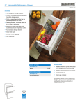
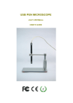
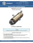
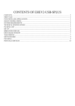
INSTALLATION GUIDE
Undercounter Refrigeration
Contents
Important Note
Undercounter Refrigeration . . . . . . . . . . . . . . . . . . . . . 3
To ensure the safe and efficient installation of Sub-Zero
equipment, please take note of the following types of
highlighted information throughout this guide:
Undercounter Specifications . . . . . . . . . . . . . . . . . . . . 4
Site Preparation . . . . . . . . . . . . . . . . . . . . . . . . . . . . . . 5
Undercounter Installation . . . . . . . . . . . . . . . . . . . . . . 7
Service Information . . . . . . . . . . . . . . . . . . . . . . . . . . 14
Features and specifications are subject to change at any time
without notice. Visit subzero.com/specs for the most up-todate information.
IMPORTANT NOTE: Throughout this guide, dimensions in
parentheses are millimeters unless otherwise specified.
IMPORTANT NOTE highlights information that is especially
relevant to a problem-free installation.
CAUTION signals a situation where minor injury or product
damage may occur if instructions are not followed.
WARNING states a hazard that may cause serious injury or
death if precautions are not followed.
Undercounter Refrigeration
3
subzero.com/specs
Sub-Zero Undercounter Refrigeration
IMPORTANT NOTE: The importance of the installation of
the Sub-Zero undercounter unit cannot be overemphasized. Installation should be done by a qualified installer.
RATING PLATE
Before you begin the installation process, it is recommended that you read this entire installation guide. There
are key details that you should take special care to
observe during the installation. By reading these instructions carefully, you will make the installation process
easier, problem-free and, most importantly, safe.
Any questions or problems regarding the installation
should be directed to your authorized Sub-Zero dealer or
Sub-Zero customer care at 800-222-7820. You may also
check the contact & support section of our website,
subzero.com.
Important product information, including the model and
serial number of your unit are listed on the product rating
plate, located inside the cabinet, in the upper left area of
the unit. Refer to the illustration.
Location of rating plate.
Undercounter Specifications
4
Undercounter Models
OVERALL DIMENSIONS
23 7/8" (606)
OPENING DIMENSIONS
24" (610)
TOP VIEW
24" (610)
OPENING
DEPTH
34"
(864)
4" (102)
24" (610)
OPENING DEPTH
341/2" (876)
OPENING
HEIGHT
24" (610)
OPENING WIDTH
25 3/8"
(645)
SIDE VIEW
1 3/4" (44)
SPECIFICATIONS
Shipping Weight
lbs (kg)
All Models
130 (59)
FRONT VIEW
Site Preparation
5
subzero.com/specs
Before You Start
Make sure the opening dimensions, door clearance,
electrical service and plumbing are correct for the model
you are about to install. Refer to specifications on the
following pages.
TOOLS AND MATERIALS REQUIRED
IMPORTANT NOTE: To operate properly, the door must
open a minimum of 90°. Use a minimum 3" (76) filler in
corner installations to assure a 90° door opening. Allow
enough clearance in front of the unit for full door swing.
• Phillips and slotted screwdriver sets
• Appliance dolly able to support 130 lbs (59 kg)
• Level — 2' (.6 m) and 4' (1.2 m) recommended
• Wrench set and allen wrench set
• Crescent wrenches
• Various sized pliers
•
5/16"
hex bolt nut driver
• Drill and assorted drill bits
• Model UC-24CI—4' (1.2 m) of 1/4" copper, braided
stainless steel or PEX tubing and saddle valve for
water line (do not use self-piercing valves).
• Model UC-24CI—Tubing cutter.
• Masonite, plywood, 1/8" pressed fiberboard, cardboard
or other suitable material to protect finished flooring
Site Preparation
6
Electrical Requirements
Plumbing Requirements
The electrical supply should be located within the shaded
area shown in the illustration below. Follow the National
Electrical Code and local codes and ordinances when
installing the receptacle. A separate circuit, servicing only
this appliance is required.
MODEL UC-24CI
IMPORTANT NOTE: The electrical outlet must be placed
so the grounding prong is to the right of the thinner
blades. The outlet must be flush with the back wall.
Model UC-24RO is designed and safe for use in outdoor
applications. When installed outdoors, a ground fault
circuit interrupter (GFCI) is required to reduce the risk of
electrical shock. A GFCI is not recommended for use with
other undercounter models and may cause interruption of
operation.
Do not use an extension cord or two-prong adapter.
Electrical ground is required on this appliance.
Electrical Requirements
Power Supply
A line filter is required when water conditions have a high
sediment content. The ice maker operates on water
pressure of 20 psi (1.4 bar) to 100 psi (6.9 bar).
A reverse osmosis system can be used, provided there is
a consistent water pressure of 20 psi (1.4 bar) to 100 psi
(6.9 bar) supplied to the water valve at all times. A copper
line is not recommended for this application.
IMPORTANT NOTE: In some cases a reverse osmosis
water filter system may not be able to maintain the
minimum water pressure consistently.
Plumbing Requirements
115 V AC, 60 Hz
Circuit Breaker
For model UC-24CI, the water supply line for the ice
maker should be located within the shaded area shown in
the illustration below. Connect the water line from the ice
maker water valve to the house water supply line. Use an
easily accessible shut-off valve between the water supply
and the unit. Do not use self-piercing valves. A saddle
valve kit is available from your authorized Sub-Zero
dealer.
1/4"
Water Supply Line
15 amp
Receptacle
3-prong grounding-type
OD copper, braided stainless steel
or PEX tubing
Water Pressure
20–100 psi (1.4–6.9 bar)
Excess Water Line for Connection
LEFT SIDE
OF OPENING
SHADED AREA
EXTENDS 1/2" (13)
FROM BACK WALL
2" (51)
15 1/2"
2" (51)
(394)
3" (76)
15 1/2"
(394)
3" (76)
FRONT VIEW
FRONT VIEW
Location of electrical supply.
Location of water supply.
26" (660) min
Undercounter Installation
7
subzero.com/specs
Unpack the Unit
Before moving the undercounter unit into position, make
sure all opening dimensions, electrical and plumbing
requirements are complete and accurate.
IMPORTANT NOTE: The floor under the undercounter unit
must be at the same level as the surrounding finished floor
to allow for removal of the unit for servicing.
Use an appliance dolly to move the undercounter unit near
the installation opening. Position the dolly at the side of
the unit to prevent damage to finished surfaces. Remove
and discard all packing materials and tape.
IMPORTANT NOTE: Do not discard the kickplate, anti-tip
bracket, hardware and the shipping bolts that hold the
wood to the bottom of the unit (leveling legs). These items
will be needed for the installation.
For models UC-24BG and UC-24C(I), the roller-assembly
wine shelves should be removed to reduce weight and
prevent them from rolling. To remove, pull the shelf out to
its full extension, gently and evenly lift up on both sides of
the front of the shelf and remove. Reverse the procedure
to reinstall the shelf.
Anti-Tip Bracket
To prevent the unit from tipping forward and provide a
stable installation, the unit must be secured in place
with the anti-tip bracket.
An anti-tip bracket and hardware is provided with the
undercounter unit. Placement of the anti-tip bracket is
critical to a stable installation. The anti-tip bracket must be
installed securely.
The anti-tip bracket should be attached to the wall behind
the unit with the bracket flange located immediately above
the top of the unit. Refer to the illustration below.
For installations that cannot accommodate the anti-tip
bracket, the optional countertop bracket (provided) can
be used to secure the undercounter unit. This bracket will
secure the front of the unit to the underside of the countertop, above the unit. Refer to the illustration below. If it is
not possible to use the countertop bracket, wedge shims
along the sides and top of the unit to secure.
Before moving the undercounter unit into position,
protect any finished flooring with appropriate materials
and secure the door closed.
ANTI-TIP
BRACKET
COUNTERTOP
BRACKET
1/4" (6)
Anti-tip bracket.
Countertop bracket.
Undercounter Installation
8
Installation
IMPORTANT NOTE: If the undercounter unit has been laid
on its back or side, you must allow the unit to stand upright
for a minimum of 24 hours before connecting power.
With the undercounter unit near the installation opening,
plug the power cord into the electrical outlet. With power
applied to the unit, check for lighting and cooling. Once
you are satisfied that the unit is operating properly, shut
off power to the electrical outlet at the circuit breaker and
proceed.
LEVEL THE UNIT
Level the unit before sliding it into position. Leveling
cannot be completed with the unit pushed back in the
installation opening.
Using an adjustable wrench or pliers, turn each of the four
leveling legs clockwise to raise the unit and counterclockwise to lower the unit. For the location of the leveling legs,
refer to the illustration.
WATER LINE CONNECTION (MODEL UC-24CI)
For model UC-24CI, connect the plastic tubing from the
ice maker to the house water supply line with the fitting
connection kit, provided. Check all water line fittings for
leaks.
Purge the water line prior to final connection to the unit.
This will remove any debris that may be present in the
tubing from installing the new water line.
IMPORTANT NOTE: Let your customer know that the ice
maker will not produce ice immediately, and that the first
few batches of ice produced should be discarded. Allow
24 hours for proper ice production.
IMPORTANT NOTE: Water lines must not be exposed to
freezing temperatures. Exposure could cause damage to
the unit and home.
INSTALL KICKPLATE
Install the kickplate using the two #10 x 1/2" stainless steel
screws that are provided with the kickplate. Refer to the
illustration below.
To reduce the possibility of the unit tipping forward, the
front leveling legs must be in contact with the floor.
POSITION THE UNIT
The kickplate must be removed for servicing. The floor
cannot interfere with removal. Do not cover the louvered
section of the kickplate to allow proper air circulation.
Turn power back on to the electrical outlet.
Slide the undercounter unit back into position in the
installation opening. Make sure it contacts the anti-tip
bracket for a stable installation.
The undercounter unit provides the best access to its
contents when the front surface of the door panel extends
out from surrounding cabinets approximately 1/4" (6).
KICKPLATE
LEVELING LEGS
Location of leveling legs.
Kickplate installation.
Undercounter Installation
9
subzero.com/specs
Door Panel
MODELS UC-24R AND UC-24C(I)
Panel Specifications
Models UC-24R and UC-24C(I) can be fitted with a
custom overlay or stainless steel door front panel. A stainless steel door panel with tubular or pro handle is available
as a sales accessory. Installation of the stainless steel
panel will be required.
OVERLAY PANEL
For the overlay application, a decorative door panel and
handle hardware must be provided. Refer to the chart for
panel specifications.
You can match your handle hardware with surrounding
cabinetry or use a Sub-Zero accessory handle. Handles
must be attached directly to the overlay panel.
UC-24R, UC-24BG, UC-24C(I)
W
H
23 3/4" (603)
30 1/16" (764)
RAILS AND STILES
UC-24BG
W
2 1/4" (57) min
MAX PANEL WEIGHT
UC-24R and UC-24C(I)
UC-24BG
20 lbs (9 kg)
10 lbs (5 kg)
MIN PANEL THICKNESS
Overlay Panels
5/8"
(16)
OUTDOOR MODEL UC-24RO
BEVERAGE CENTER MODEL UC-24BG
Model UC-24RO is shipped from the factory with the
stainless steel door panel and tubular or pro handle in
place. No panel installation is required.
Stainless steel model UC-24BG/S is shipped from the
factory with the stainless steel door panel and tubular or
pro handle in place. No panel installation is required.
IMPORTANT NOTE: Model UC-24RO must be built into
cabinetry and cannot be used in a freestanding application.
For overlay model UC-24BG/O, a decorative frame door
panel must be provided to surround the glass. The inside
edges of the panel that will be visible through the glass
must be finished. Refer to the chart for panel specifications.
You may also use your own handle hardware to match surrounding cabinetry. If you do not use the pre-drilled holes
on the door of the unit, you will need to attach the handle
directly to the overlay panel.
IMPORTANT NOTE: For installations at or above 5,000'
(1524 m) in altitude, a special high altitude glass door unit
must be ordered.
A solid panel must not be installed over the glass door,
as this may cause moisture to form behind the panel.
Undercounter Installation
10
Overlay Panel Installation
MODELS UC-24R AND UC-24C(I)
Inspect the overlay door panel for minimum thickness and
weight limit. Remove the two panel mounting brackets
attached to the front of the door and set aside.
Place the overlay panel lying face down on a protected
surface to ensure that the front is not scratched or
damaged. Position the plastic template (provided) flush
with the lower edge of the door panel. Be sure you are
following the exact location for the right-hand (RH) or lefthand (LH) door swing. Refer to the illustration below for
placement of the mounting brackets.
Once you have located the proper placement for the
brackets, mark the pilot holes, remove the template and
drill pilot holes for mounting the brackets. It is best to start
with a few holes, position the bracket, drill the remaining
pilot holes and then secure the mounting bracket with the
#8 x 1/2" screws provided.
Exercise caution when drilling holes for mounting
hardware. This is especially critical with inset panels.
Before attaching the overlay panel to the door, insert two
screws, one in the center of each mounting position, just
far enough that the slotted holes on the hinge side door
panel bracket will slide under the heads. These positioning
screws will support the door panel during installation and
adjustment. Refer to the illustration below.
Install the door panel by engaging the tabbed bracket to
the handle side of the door first and then sliding the hinge
side mounting bracket onto the positioning screws on the
hinge side of the door. The panel can be adjusted 1/4" (6)
up and down and side to side.
Once the door panel is in place and adjusted correctly,
attach the four remaining #10 x 1/2" screws to the hinge
side mounting bracket and install the magnetic decorative
caps as shown in the illustration below.
DOOR
PANEL
BRACKET
SCREW
21 5/8" (549)
CAP
7/8"
(22)
Panel installation.
30 1/16"
RH DOOR SWING
(764)
15 1/16"
(382)
3 5/8"
3 1/2"
(92)
(89)
23 3/4" (603)
Overlay panel bracket location.
LH DOOR SWING
Undercounter Installation
11
subzero.com/specs
Overlay Panel Installation
BEVERAGE CENTER MODEL UC-24BG
Inspect the overlay door panel for minimum thickness,
weight limit and finished inside edges. Decide if the handle
will be attached through the glass door frame or just
through the decorative door panel. If it is just through the
door panel, the handle must be attached first.
The overlay door panel is attached using #8 x 5/8" square
drive screws passing through the door frame from the rear,
behind the gasket into the panel. The door panel is
marked for screw locations by the use of tenon centers,
which are temporarily inserted into the 1/4" (6) diameter
holes in the front of the door frame. Refer to the illustration
below.
With the unit secured in place and the door closed, the
panel is held in the desired position on the door and
rapped by hand from the front, putting center marks on
the rear surface of the panel. If the door panel is made of
such a material that pre-drilling is needed, all of the
mounting holes should be marked. If not, only enough
holes to hold the panel in place temporarily, are necessary.
GASKET
OVERLAY
PANEL
13/32" (11)
DIAMETER
DOOR
FRAME
GLASS
1/4" (6)
DIAMETER
TENON CENTER
Tenon centers.
Door frame cross section.
Remove the door panel from the door frame and remove
tenon centers. Open the door. Using the center marks to
locate screws, drive the screws into the panel through the
black tape on the door frame.
The screw holes inside the door are hidden under a cover
flap on the door gasket. It is necessary to lift the flap to
insert the screws. Use as many screws as necessary to
hold the door panel in place securely.
IMPORTANT NOTE: After the first three or four mounting
screws are in place, but not completely tightened, close
the door and check the panel fit. This is the time to make
small adjustments. Once you are satisfied with the appearance, open the door and add the rest of the screws.
Check all screws for tightness.
The metal frame on the door has numerous mounting
holes on each side of the door. This is to accommodate
Sub-Zero accessory handles and provide for easy attachment of the handle through the door frame.
If you choose not to use the pre-drilled handle mounting
holes, it will be necessary to fasten the handle from the
rear of the door panel only, or drill one or more additional
holes through the metal frame of the door.
The cross-section illustration shows how the hole passes
through the door frame. The hole center is on the small
locator groove in the front of the frame. A 1/4" (6) diameter
hole is made in the front wall of the extrusion and a 13/32"
(11) diameter hole through the rest of the frame.
Undercounter Installation
Overlay Panel Installation
The model UC-24BG glass door is made with a sealed,
double-wall tempered glass core. The drill must not
contact this core when drilling. Be sure the hole is
centered on the small groove in the front of the door
frame and the drill passes squarely through the frame.
If you are inexperienced with drilling, fasten the handle
from the rear of the door panel only.
IMPORTANT NOTE: For model UC-24BG, install screws in
all the mounting holes in the door frame. The nature of the
door panel with a narrow outer rim and no connecting
center member requires the support provided by the glass
door.
12
Hinge Adjustment
IMPORTANT NOTE: The undercounter unit should be
properly leveled before door hinge adjustments are made.
The top and bottom cabinet hinges are held in place with
three permanent adjustment screws. If the door needs
adjustment, loosen the adjustment screws and reposition
the door. Once in position, tighten the adjustment screws.
Refer to the illustrations below.
TOP DOOR
HINGE
ADJUSTMENT
SCREWS
After the door panel installation is complete, apply the
cover patches or plugs provided over the holes on the
inside surface of the door.
The cover patches or plugs are part of the insulation
system on the door of the undercounter unit. Be sure to
cover all the holes in the door that were used.
BOTTOM
DOOR HINGE
ADJUSTMENT
SCREWS
Top hinge adjustment.
Bottom hinge adjustment.
Undercounter Installation
13
subzero.com/specs
Installation Checklist
To ensure a safe and proper installation, the following
checklist should be completed by the installer to ensure
that no part of the installation has been overlooked.
Has all packing material been removed?
Turn the unit on. Is it operating properly? If not, is the
unit plugged in? Is the control turned on?
Is the power cord plugged into a properly grounded
3-prong outlet, which has been installed in accordance
with all applicable electrical codes?
Has the unit been secured in place with the anti-tip
bracket?
Is the unit level? Are all leveling legs making contact
with the floor?
Is the kickplate installed properly?
Is the water supply connected (model UC-24CI)?
Have you checked for leaks?
Is the door panel attached securely and properly
aligned?
Is the door aligned for proper appearance and
operation?
Have any installation or service problems been noted
on the product registration card? Has the registration
card been mailed in?
Has the stainless steel door or panel been inspected
for any imperfections? This is to be done by the dealer
or installer with the customer upon completion of the
installation. Stainless steel panels are covered by a
limited 60-day parts and labor warranty for cosmetic
defects.
Service Information
14
Service Information
If service is necessary, maintain the quality built into your
undercounter unit by calling Sub-Zero factory certified
service.
For the name and number of Sub-Zero factory certified
service nearest you, check the contact & support section
of our website, subzero.com or call Sub-Zero customer
care at 800-222-7820.
When calling for service, you will need the model and
serial numbers of your unit. Both numbers are listed on the
product rating plate located inside the cabinet, in the
upper left area of the unit. Refer to the illustration below.
RATING PLATE
Location of rating plate.
If you are storing or disposing of your old refrigerator
or freezer, please do it
safely. Remove the
doors or tightly secure
the doors closed.
Child entrapment
accidents can be tragic.
The information and images in this guide are the copyright property of Sub-Zero, Inc. Neither this guide nor any information or images contained herein may be
copied or used in whole or in part without the express written permission of Sub-Zero, Inc. ©Sub-Zero, Inc. all rights reserved.
Wolf, Wolf & Design, Wolf Gourmet, W & Design and the color red as applied to knobs are registered trademarks and service marks of Wolf Appliance, Inc.
Sub-Zero, Sub-Zero & Design, Dual Refrigeration, Constant Care and The Living Kitchen are registered trademarks and service marks of Sub-Zero, Inc.
(collectively, the “Company Marks.”) All other trademarks or registered trademarks are property of their respective owners in the United States and other countries.
SUB-ZERO, INC.
P. O. BOX 44848
MADISON, WI 53744
7023606 REV-A
12/2011
SUBZERO.COM
800.222.7820