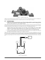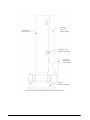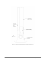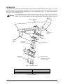
1
On-Board Weighing Systems
Installation & Service
Manual
115094
To be the best by every measure
Content
Introduction.............................................................................................................................................. 1
1.0
Considerations Before Installation .............................................................................................. 1
2.0
Recommended Service Tools ...................................................................................................... 2
2.1 Load Cells, Transducer and Load Pins . . . . . . . . . . . . . . . . . . . . . . . . . . . . . . . . . . . . . . . . . . . . . . . . 2
2.2 Indicators and Cables. . . . . . . . . . . . . . . . . . . . . . . . . . . . . . . . . . . . . . . . . . . . . . . . . . . . . . . . . . . . . 2
3.0
Load Cell Assemblies and General Specifications ..................................................................... 3
3.1
3.2
3.3
3.4
3.5
3.6
3.7
3.8
3.9
4.0
Feed Wagon Cantilever Beam . . . . . . . . . . . . . . . . . . . . . . . . . . . . . . . . . . . . . . . . . . . . . . . . . . . . . .
Low Profile Bending Beam Load Cell . . . . . . . . . . . . . . . . . . . . . . . . . . . . . . . . . . . . . . . . . . . . . . . . .
Underbody Shear Beam Load Cell . . . . . . . . . . . . . . . . . . . . . . . . . . . . . . . . . . . . . . . . . . . . . . . . . . .
Heavy Duty Shear Beam Load Cell . . . . . . . . . . . . . . . . . . . . . . . . . . . . . . . . . . . . . . . . . . . . . . . . . . .
Underbody/Axle Scale Load Cell . . . . . . . . . . . . . . . . . . . . . . . . . . . . . . . . . . . . . . . . . . . . . . . . . . . .
Heavy Duty Bunk / Underbody Load Cell . . . . . . . . . . . . . . . . . . . . . . . . . . . . . . . . . . . . . . . . . . . . . .
5th Wheel / Suspension Load Cell . . . . . . . . . . . . . . . . . . . . . . . . . . . . . . . . . . . . . . . . . . . . . . . . . . .
Load Pins . . . . . . . . . . . . . . . . . . . . . . . . . . . . . . . . . . . . . . . . . . . . . . . . . . . . . . . . . . . . . . . . . . . . . .
Air Pressure Transducer . . . . . . . . . . . . . . . . . . . . . . . . . . . . . . . . . . . . . . . . . . . . . . . . . . . . . . . . . . .
3
4
5
5
6
7
8
9
9
Applications ............................................................................................................................... 10
4.1 Air Pressure Transducer . . . . . . . . . . . . . . . . . . . . . . . . . . . . . . . . . . . . . . . . . . . . . . . . . . . . . . . . . . 10
4.1.1
4.1.2
4.1.3
Installation Procedure . . . . . . . . . . . . . . . . . . . . . . . . . . . . . . . . . . . . . . . . . . . . . . . . . . . . . . . . . . . . . 11
Slip Spring/Torque Arm Air Suspension. . . . . . . . . . . . . . . . . . . . . . . . . . . . . . . . . . . . . . . . . . . . . . . . 13
Technical Specifications . . . . . . . . . . . . . . . . . . . . . . . . . . . . . . . . . . . . . . . . . . . . . . . . . . . . . . . . . . . 14
4.2 Underbody Load Cell Mounts . . . . . . . . . . . . . . . . . . . . . . . . . . . . . . . . . . . . . . . . . . . . . . . . . . . . . . 14
4.2.1
4.2.2
4.2.3
4.2.4
Underbody Mounting Brackets . . . . . . . . . . . . . . . . . . . . . . . . . . . . . . . . . . . . . . . . . . . . . . . . . . . . . .
Underbody Mounting of Load Cells . . . . . . . . . . . . . . . . . . . . . . . . . . . . . . . . . . . . . . . . . . . . . . . . . . .
Stress Concentrations and Frame Reinforcing . . . . . . . . . . . . . . . . . . . . . . . . . . . . . . . . . . . . . . . . . . .
Underbody Load Cell Mounting . . . . . . . . . . . . . . . . . . . . . . . . . . . . . . . . . . . . . . . . . . . . . . . . . . . . . .
15
17
21
22
4.3 Kingpin Plate Mounts . . . . . . . . . . . . . . . . . . . . . . . . . . . . . . . . . . . . . . . . . . . . . . . . . . . . . . . . . . . . 23
4.3.1
4.3.2
4.3.3
Skid Plate Preparation . . . . . . . . . . . . . . . . . . . . . . . . . . . . . . . . . . . . . . . . . . . . . . . . . . . . . . . . . . . . . 23
Trailer Body Preparation . . . . . . . . . . . . . . . . . . . . . . . . . . . . . . . . . . . . . . . . . . . . . . . . . . . . . . . . . . . 25
Installation Procedure . . . . . . . . . . . . . . . . . . . . . . . . . . . . . . . . . . . . . . . . . . . . . . . . . . . . . . . . . . . . . 26
4.4 Equalizer Hanger Mounts . . . . . . . . . . . . . . . . . . . . . . . . . . . . . . . . . . . . . . . . . . . . . . . . . . . . . . . . . 27
4.4.1
4.4.2
Preparation . . . . . . . . . . . . . . . . . . . . . . . . . . . . . . . . . . . . . . . . . . . . . . . . . . . . . . . . . . . . . . . . . . . . . 27
Assembly . . . . . . . . . . . . . . . . . . . . . . . . . . . . . . . . . . . . . . . . . . . . . . . . . . . . . . . . . . . . . . . . . . . . . . 28
4.5 Fixed 5th Wheel Mounts . . . . . . . . . . . . . . . . . . . . . . . . . . . . . . . . . . . . . . . . . . . . . . . . . . . . . . . . . . 30
4.5.1
Installation Procedure . . . . . . . . . . . . . . . . . . . . . . . . . . . . . . . . . . . . . . . . . . . . . . . . . . . . . . . . . . . . . 31
4.6 Hinge and Hoist Pivot Pin Installation . . . . . . . . . . . . . . . . . . . . . . . . . . . . . . . . . . . . . . . . . . . . . . . . 32
4.6.1
4.6.2
Installation Procedure . . . . . . . . . . . . . . . . . . . . . . . . . . . . . . . . . . . . . . . . . . . . . . . . . . . . . . . . . . . . . 33
Hinge Bar and Lift Cylinder Pin . . . . . . . . . . . . . . . . . . . . . . . . . . . . . . . . . . . . . . . . . . . . . . . . . . . . . . 35
4.7 Body Rest Mounts . . . . . . . . . . . . . . . . . . . . . . . . . . . . . . . . . . . . . . . . . . . . . . . . . . . . . . . . . . . . . . 37
4.7.1
Installation Procedure . . . . . . . . . . . . . . . . . . . . . . . . . . . . . . . . . . . . . . . . . . . . . . . . . . . . . . . . . . . . . 37
4.8 Trunnion Load Pin Installation . . . . . . . . . . . . . . . . . . . . . . . . . . . . . . . . . . . . . . . . . . . . . . . . . . . . . . 39
4.9 Sandshoe Load Pin for Landing Gear . . . . . . . . . . . . . . . . . . . . . . . . . . . . . . . . . . . . . . . . . . . . . . . . 41
4.9.1
Installation Procedure . . . . . . . . . . . . . . . . . . . . . . . . . . . . . . . . . . . . . . . . . . . . . . . . . . . . . . . . . . . . . 41
4.10 Single Point Suspension Clamp Load Cell Mount Installation. . . . . . . . . . . . . . . . . . . . . . . . . . . . . . 44
Technical training seminars are available through Rice Lake Weighing Systems.
Course descriptions and dates can be viewed at www.ricelake.com/training
or obtained by calling 715-234-9171 and asking for the training department.
© 2011 Rice Lake Weighing Systems. All rights reserved. Printed in the United States of America.
Specifications subject to change without notice.
Rice Lake Weighing Systems is an ISO 9001 registered company.
i
4.11 PL9710 and PL9740 Output Ports . . . . . . . . . . . . . . . . . . . . . . . . . . . . . . . . . . . . . . . . . . . . . . . . . 48
5.0
Service and Troubleshooting..................................................................................................... 50
5.1 System Maintenance . . . . . . . . . . . . . . . . . . . . . . . . . . . . . . . . . . . . . . . . . . . . . . . . . . . . . . . . . . . . 50
5.2 Calibration . . . . . . . . . . . . . . . . . . . . . . . . . . . . . . . . . . . . . . . . . . . . . . . . . . . . . . . . . . . . . . . . . . . . 50
5.3 Sensor Maintenance . . . . . . . . . . . . . . . . . . . . . . . . . . . . . . . . . . . . . . . . . . . . . . . . . . . . . . . . . . . . 50
5.3.1
5.3.2
5.3.3
Load Cells. . . . . . . . . . . . . . . . . . . . . . . . . . . . . . . . . . . . . . . . . . . . . . . . . . . . . . . . . . . . . . . . . . . . . . 50
Load Pins . . . . . . . . . . . . . . . . . . . . . . . . . . . . . . . . . . . . . . . . . . . . . . . . . . . . . . . . . . . . . . . . . . . . . . 50
Visual Inspection . . . . . . . . . . . . . . . . . . . . . . . . . . . . . . . . . . . . . . . . . . . . . . . . . . . . . . . . . . . . . . . . . 50
5.4 Cables and Connectors . . . . . . . . . . . . . . . . . . . . . . . . . . . . . . . . . . . . . . . . . . . . . . . . . . . . . . . . . . 51
5.4.1
5.4.2
5.4.3
Cables . . . . . . . . . . . . . . . . . . . . . . . . . . . . . . . . . . . . . . . . . . . . . . . . . . . . . . . . . . . . . . . . . . . . . . . . 51
Connections . . . . . . . . . . . . . . . . . . . . . . . . . . . . . . . . . . . . . . . . . . . . . . . . . . . . . . . . . . . . . . . . . . . . 51
Truck/Trailer Connector . . . . . . . . . . . . . . . . . . . . . . . . . . . . . . . . . . . . . . . . . . . . . . . . . . . . . . . . . . . 51
5.5 System Troubleshooting . . . . . . . . . . . . . . . . . . . . . . . . . . . . . . . . . . . . . . . . . . . . . . . . . . . . . . . . . 51
5.5.1
5.5.2
5.5.3
5.5.4
Error Messages. . . . . . . . . . . . . . . . . . . . . . . . . . . . . . . . . . . . . . . . . . . . . . . . . . . . . . . . . . . . . . . . . .
Test . . . . . . . . . . . . . . . . . . . . . . . . . . . . . . . . . . . . . . . . . . . . . . . . . . . . . . . . . . . . . . . . . . . . . . . . . .
Isolate . . . . . . . . . . . . . . . . . . . . . . . . . . . . . . . . . . . . . . . . . . . . . . . . . . . . . . . . . . . . . . . . . . . . . . . . .
Calibration . . . . . . . . . . . . . . . . . . . . . . . . . . . . . . . . . . . . . . . . . . . . . . . . . . . . . . . . . . . . . . . . . . . . .
51
52
52
52
5.6 Cal Factors . . . . . . . . . . . . . . . . . . . . . . . . . . . . . . . . . . . . . . . . . . . . . . . . . . . . . . . . . . . . . . . . . . . 53
5.7 Application-Specific Service Notes . . . . . . . . . . . . . . . . . . . . . . . . . . . . . . . . . . . . . . . . . . . . . . . . . 53
5.7.1
5.7.2
Spring-mounted Load Cells . . . . . . . . . . . . . . . . . . . . . . . . . . . . . . . . . . . . . . . . . . . . . . . . . . . . . . . . 53
Trunnion Load Pins . . . . . . . . . . . . . . . . . . . . . . . . . . . . . . . . . . . . . . . . . . . . . . . . . . . . . . . . . . . . . . . 53
5.8 Lift-to-Weigh Program . . . . . . . . . . . . . . . . . . . . . . . . . . . . . . . . . . . . . . . . . . . . . . . . . . . . . . . . . . . 54
5.8.1
Air Pressure Transducers . . . . . . . . . . . . . . . . . . . . . . . . . . . . . . . . . . . . . . . . . . . . . . . . . . . . . . . . . . 54
5.9 Connector Pin-outs, Color Codes . . . . . . . . . . . . . . . . . . . . . . . . . . . . . . . . . . . . . . . . . . . . . . . . . . 54
5.10 .Error Messages. . . . . . . . . . . . . . . . . . . . . . . . . . . . . . . . . . . . . . . . . . . . . . . . . . . . . . . . . . . . . . . 55
5.11 Test Mode . . . . . . . . . . . . . . . . . . . . . . . . . . . . . . . . . . . . . . . . . . . . . . . . . . . . . . . . . . . . . . . . . . . 57
5.11.1
6.0
Recording Test Numbers . . . . . . . . . . . . . . . . . . . . . . . . . . . . . . . . . . . . . . . . . . . . . . . . . . . . . . . . . . 57
Appendix .................................................................................................................................... 58
6.1 Bolt Torque Values . . . . . . . . . . . . . . . . . . . . . . . . . . . . . . . . . . . . . . . . . . . . . . . . . . . . . . . . . . . . . 58
6.2 Spring Bolt Mountings . . . . . . . . . . . . . . . . . . . . . . . . . . . . . . . . . . . . . . . . . . . . . . . . . . . . . . . . . . . 58
6.3 Welding Specifications. . . . . . . . . . . . . . . . . . . . . . . . . . . . . . . . . . . . . . . . . . . . . . . . . . . . . . . . . . . 59
6.3.1
6.3.2
6.3.3
6.3.4
Preparation . . . . . . . . . . . . . . . . . . . . . . . . . . . . . . . . . . . . . . . . . . . . . . . . . . . . . . . . . . . . . . . . . . . . .
Installation Procedure . . . . . . . . . . . . . . . . . . . . . . . . . . . . . . . . . . . . . . . . . . . . . . . . . . . . . . . . . . . . .
Inspection . . . . . . . . . . . . . . . . . . . . . . . . . . . . . . . . . . . . . . . . . . . . . . . . . . . . . . . . . . . . . . . . . . . . . .
Bolt Torque Verification . . . . . . . . . . . . . . . . . . . . . . . . . . . . . . . . . . . . . . . . . . . . . . . . . . . . . . . . . . . .
60
60
60
60
6.4 Transmitter Installation and Cabling . . . . . . . . . . . . . . . . . . . . . . . . . . . . . . . . . . . . . . . . . . . . . . . . . 61
6.4.1
6.4.2
6.4.3
6.4.4
Transmitter location . . . . . . . . . . . . . . . . . . . . . . . . . . . . . . . . . . . . . . . . . . . . . . . . . . . . . . . . . . . . . .
Mounting the transmitter . . . . . . . . . . . . . . . . . . . . . . . . . . . . . . . . . . . . . . . . . . . . . . . . . . . . . . . . . . .
Installing the Cables . . . . . . . . . . . . . . . . . . . . . . . . . . . . . . . . . . . . . . . . . . . . . . . . . . . . . . . . . . . . . .
Power Access. . . . . . . . . . . . . . . . . . . . . . . . . . . . . . . . . . . . . . . . . . . . . . . . . . . . . . . . . . . . . . . . . . .
61
61
61
61
6.5 Equalizer Hanger Modification . . . . . . . . . . . . . . . . . . . . . . . . . . . . . . . . . . . . . . . . . . . . . . . . . . . . .
6.6 Hinge Bar Installation Drawing . . . . . . . . . . . . . . . . . . . . . . . . . . . . . . . . . . . . . . . . . . . . . . . . . . . . .
6.7 Underbody Load Cell Chassis and Body Brackets Drawings . . . . . . . . . . . . . . . . . . . . . . . . . . . . . .
6.8 5th Wheel Mounts for Pole Trailers and Dump Trailers . . . . . . . . . . . . . . . . . . . . . . . . . . . . . . . . . .
6.9 Trailer Rear Hanger Assembly . . . . . . . . . . . . . . . . . . . . . . . . . . . . . . . . . . . . . . . . . . . . . . . . . . . . .
6.10 PL9710 Indicators with PL9774 Limit Setpoint Option . . . . . . . . . . . . . . . . . . . . . . . . . . . . . . . . . .
62
63
64
67
68
69
6.10.1
6.10.2
6.10.3
6.10.4
System Configurations . . . . . . . . . . . . . . . . . . . . . . . . . . . . . . . . . . . . . . . . . . . . . . . . . . . . . . . . . . . .
Limit Module Connections. . . . . . . . . . . . . . . . . . . . . . . . . . . . . . . . . . . . . . . . . . . . . . . . . . . . . . . . . .
Program Setup . . . . . . . . . . . . . . . . . . . . . . . . . . . . . . . . . . . . . . . . . . . . . . . . . . . . . . . . . . . . . . . . . .
Operation . . . . . . . . . . . . . . . . . . . . . . . . . . . . . . . . . . . . . . . . . . . . . . . . . . . . . . . . . . . . . . . . . . . . . .
69
69
70
70
Hardware Warranty Statement .............................................................................................................. 72
Rice Lake continually offers web-based video training on a growing selection
of product-related topics at no cost. Visit www.ricelake.com/webinars.
ii
Precision Loads On-Board Weighing Installation & Service Manual
Introduction
This manual is intended for use by technicians
responsible for installing and servicing On-Board
Weighing Systems.
This manual contains instructions for installing
various types of On-board Weighing Systems (non
Legal-for-Trade systems). For straight trucks, this
manual includes rigid underbody mounting
instructions in four and six point configurations, as
well as underbody load pin installation instructions for
tipping bodies and hoist chassis. Tipping body
installations can be either Lift-to-Weigh or
Live-Weigh system types.
1.0
For tractor/trailer applications, this manual covers a
variety of installation instructions, which include air
pressure transducers for tractor and/or trailer air-ride
suspensions, and load cell mounting instructions for
tractor 5th wheels and/or trailer kingpin plates,
equalizing spring suspensions, suspension subframe
mounts and single point suspension trunnion mounts.
Authorized distributors and their employees
can view or download this manual from the
Rice Lake Weighing Systems distributor site
at www.ricelake.com.
Considerations Before Installation
This manual is intended to provide information for the mounting of On-Board Weighing Systems sensors in a
variety of applications. In applying the installation procedures, which follow, some fundamental precautions and
recommendations must be observed by the installer:
• Rice Lake Weighing Systems’ On-Board Scales are designed for applications covering a broad range of
vehicle types. The installer however, needs to be aware of any significant variations in mountings,
variations in load sensor models, specifications and system configurations.
• Installation procedures are basically identical for both new vehicle mountings and retro-fit mountings,
however the installer must ensure, in the case of retro-fit mountings, that all vehicle structures are free
from cracks, excessive wear, corrosion, alignment problems, etc. that can affect safety and scale
performance.
• Load cells, load cell bearing plates, mounting brackets and load cell hardware should be painted upon
installation to help protect the installation from corrosion. Industry appropriate, quality enamel paint is
recommended. For environments where high concentrations of salts are used on road surfaces,
underbody coating is recommended (3M™ Underseal™ part number 3M-8883 Universal Rubberized
Undercoating). Load cells, bearing plates, brackets and hardware should be periodically inspected for
any evidence of rust or corrosion. If areas of corrosion are present, they should be cleaned with a wire
brush and re-painted or undercoated. Any load cell connector must be connected or capped during
painting or undercoating.
• The instructions outlined herein are designed to ensure that a correct installation will provide maximum
safety, optimum system performance and accuracy, a long operating life, and reasonable installation
costs. It is therefore extremely necessary that the installer comply with all guidelines and material
specifications outlined in this manual, with special emphasis on detail and inspection of work.
• Installation must comply with appropriate regulations of the U.S. Department of Transportation (DOT),
state and local regulations, the recommended standards and practices of the Society of Automotive
Engineers (SAE), standards of the American Welding Society (AWS), and the recommendations of the
truck, trailer and body, hoist and/or suspension manufacturer.
NOTE: Failure to observe these recommendations and instructions could result in a hazardous operating condition.
Considerations Before Installation
1
2.0
Recommended Service Tools
In addition to metalworking, welding and mechanical lifting equipment commonly required to install on-board
scale systems, some necessary tools include:
2.1
Load Cells, Transducer and Load Pins
•
•
•
•
•
•
•
•
•
•
•
•
•
3/4" or 1" drive torque wrench
Socket for 5/8" bolt (15/16" socket), for chassis brackets if used.
Socket for 3/4" bolt (1-1/8" socket)
Socket for 1" bolt (1-1/2" socket)
Socket for 1-1/8" bolt (1-11/16" socket)
Socket for 1-1/4" bolt (1-7/8" socket)
Drift punch and hammer (tabbed anti-rotation plate)
Pipe Thread Sealing Tape or Teflon thread sealant (air transducer)
Alignment Shaft (2.00" CRS or as required; for welding hinge cheek plates)
Pry Bar
Wire brush and grinder
Serviceable thread locking compound
Flashlight
Dummy Load Cells
Dummy load cells are sometimes used by OEM installers to prepare for load cells being installed by the vehicle
owner once a vehicle is delivered. Dummy load cells may also be used by installers to perform final welding of
body brackets and bearing plates for perfect fitting and alignment of load cell installations. Rice Lake Weighing
Systems can supply installers with dummy load cells for any RLWS model load cell or load pin.
2.2
Indicators and Cables
•
•
•
•
•
2
Load Simulator, dual 4-pin
Volt/Ohm meter up to 2000 M Ohms or RLWS Load Cell/Transducer Field Tester
Narrow flat blade screwdriver for indicator terminals
Cable ties, wire cutter
Wire Stripper for 16-20 AWG wire
Precision Loads On-Board Weighing Installation & Service Manual
3.0
3.1
Load Cell Assemblies and General Specifications
Feed Wagon Cantilever Beam
Model PL9000-11 load cell is designed for use in feed wagon and other light duty agricultural on-board scale
applications. Rated dynamic capacity of the load cell is 7000 lbs (3175 kg). The single tie-down bolt used is 1-1/
4 -12UNF x 2.50" L and must be torqued to 1000 lb/ft. The body bracket mounting bolt holes require 3/4" coarse
thread Grade 8 bolts requiring a minimum torque of 400 lb/ft.
Figure 3-1. Model PL9000-11 Specifications
A
2.3” (58mm)
B
2.84” (72mm)
C
1.42” (36mm)
D
3.0” (76mm)
E
3/4-10 UNC x 1.0” (25mm) deep, 4 places
F
10.8” (274mm)
G
4.0” (102mm)
H
1.5” (38mm)
J
1 1/4-12 x 2 1/8” UNF SAE Grade 8 bolt and flat washer
K
2.3” (58mm)
L
1.2” (30mm)
M
3.4” (86mm)
N
5.3” (135mm)
O
11.3” (287mm)
Table 3-1. Model PL9000-11 Specifications
Load Cell Assemblies and General Specifications
3
3.2
Low Profile Bending Beam Load Cell
Model PL9000-14 load cell is designed for low profile use in a variety of on-board scale applications including
four and six point underbody mounts and body rest mounts for dump body and hoist chassis applications. Rated
dynamic capacity is 10,000 lbs (4500 kg) per load cell. The load cell is supplied with a single piece bearing plate.
Four 3/4"-16UNF x 2.00"L Grade 8 hex head cap screws bolt the load cell to its bearing plate. Angle brackets
bolt to the load cell with four 3/4"-16UNF Grade 8 bolts, to a bolt depth of 0.875" (22 mm). All eight 3/4" bolts
used on the load cell must be torqued to 400 lb/ft. This model load cell is also spring mounted in underbody
applications.
Figure 3-2. Model PL9000-14 Specifications
A
13.00” (330mm)
B
2.84” (72mm)
C
3.00” (76mm)
D
4.60” (117mm)
E
11.50” (292mm)
F
2.33” (59mm)
G
1.00” (25mm)
H
6.50” (165mm)
J
.75 x 16 UNF x .75 (19mm) deep, 4 places
K
.75 - 16 UNF x 1.75 SAE grade 8 bolts
L
1.50” (38mm)
Table 3-2. Model PL9000-14 Specifications
4
Precision Loads On-Board Weighing Installation & Service Manual
3.3
Underbody Shear Beam Load Cell
Model PL9000-14.4 load cell is designed for underbody and body rest mounts in four and six point system kit
configurations. Rated dynamic capacity of the load cell is 12,500 lb (5700 kg). End bolts of the load cell are 1-1/
8"-12UNF x 3.25" L Grade 8 and two bolts and washers are required for cell tie down. The load cell is supplied
with a single-piece bearing plate. Brackets mount to the load cell with two 1" diameter bolts. Bolt torque for the
1"bolt is 800 lb/ft (1085 Nm). This model load cell is also spring mounted in underbody applications.
Figure 3-3. Model PL9000-14.4 Cell Specifications
3.4
Heavy Duty Shear Beam Load Cell
Model PL9000-16 load cell is used in very heavy duty on-board scale applications, particularly with the bolt-on
clamp assembly for single point trunnion mounts. This load cell can also be used in 5th wheel, body pivot or
body rest mounts due to its high dynamic weighing capacity. The load cell has a dynamic rated capacity of
40,000 lb (18,100 kg). A single piece bearing plate is supplied with the load cell which assembles to the cell with
two 1-1/8" -12UNF x 3.25" L Grade 8 bolts and washers. The top bolt pattern of the load cell is identical to the
PL9000-50 load cell allowing it to be fit with Holland and Fontaine 5th wheel trunnions. Model PL9000-50S
Shear Slugs are required when assembling a PL9000-16 load cell. The 1-1/8" bolts must be torqued to 1000 lb/ft
(1355 Nm), and the four each 3/4" bolts used with this load cell must be torqued to 400 lb/ft (542 Nm).
Figure 3-4. Model PL9000-16 Specifications
A
16.25” (412.8mm)
B
3.375” (85.7mm)
C
7.00” (177.8mm)
D
1.625” (41.3mm)
E
13.50” (342.9mm)
Table 3-3. Model PL9000-16 Specifications
Load Cell Assemblies and General Specifications
5
F
2.125” (54mm)
G
1.00”DIA x .25” DP (25.40mm DIA x 6.35mm DP)
H
.75-16 UNF x 1.00” (25.4mm) DP
I
1 3/16” (30.16 mm) DIA 2 PL
J
1.00” (25.4mm)
4 PM
Table 3-3. Model PL9000-16 Specifications
3.5
Underbody/Axle Scale Load Cell
Model PL9000-22 load cell uses two separate bearing plates, one per end. The load cell is used for underbody
mounts, and in axle scales as a replacement for load cells of other manufacturers. Rated dynamic capacity of the
load cell is 12500 lb (5670 kg). For axle scales, the load cell is rated at 30,000 lb (13600 kg) static capacity. The
load cell assemblies are fastened to bearing plates with a 1"-14 UNF x 2.50" L Grade 8 hex head cap screw. The
top surface of the load cell has three 1"-14UNF bolt holes and two 7/8"-14UNF bolt holes for mounting of
brackets or weighbridge ends. The 7/8" and 1" bolts must all be torqued to 800 lb/ft (1084 Nm), except bolts used
for spring mounts. Check for thread depth and bolt penetration into the cell to ensure the outer top surface bolts
in the load cell ear cannot bottom-out under load. See “Bolt Torque Values” on page 58 for cautions on bolt
length for “eared” load cells.
Figure 3-5. Model PL9000-22 Specifications
A
16.74” (425mm)
B
7.50” (190mm)
C
5.75” (146mm)
D
3.0” (76mm)
E
2.84” (72mm)
F
1-14 UNS x 0.8” (20mm) deep, 3 places
G
7/8 - 14 UNF x 0.8” (20mm) deep, 2 places
H
22.6” (574mm)
J
19.6” (498mm)
K
1-14 UNS x 2.5” SAE Grade 8 bolt and flat washer)
L
3.575” (91mm)
M
1.275” (32mm)
Table 3-4. Model PL9000-22 Specifications
6
Precision Loads On-Board Weighing Installation & Service Manual
N
1.2” (30mm)
O
3.3” (84 mm)
P
13.8” (351mm)
Q
24.6” (625mm)
Table 3-4. Model PL9000-22 Specifications
3.6
Heavy Duty Bunk / Underbody Load Cell
Model PL9000-26 load cell is a heavy duty shear beam load cell used for kingpin plate, underbody and
under-bunk (beneath a log bunk) mounts. Dynamic capacity of the load cell is 20,000 lb (9000 kg). The cell is
tied down to two separate bearing plates, one at each end using 1-1/8" -12UNF x 3.25" Long Grade 8 hex head
cap screws. These bolts must be torqued to 1000 lb/ft (1355 Nm). The top surface of the load cell has a bolt
pattern which is identical to the Model PL9000-22 cell, three 1"-14UNF bolt holes and two 7/8"-14UNF bolt
holes, each with a 1.00" thread depth. The 7/8" and 1" bolts must all be torqued to 800 lb/ft (1084 Nm), except
bolts used for spring mounts in underbody applications.
26.00 in
24.62 in
21.50 in
20.50 in
13.00 in
5.50 in
4.50 in
1.38 in
1 - 3/16 dia thru 2 PL
1-14 x 1.50
2.32 in
2.20 in
24 inch pigtail
3.00 in
Figure 3-6. Model PL9000-26 Specifications
Load Cell Assemblies and General Specifications
7
3.7
5th Wheel / Suspension Load Cell
Model PL9000-50 load cell is designed primarily for dual use as both a 5th wheel load cell and a cell for spring
suspension hanger mounts. Rated dynamic capacity of the load cell is 12,500 lb (5700 kg). The load cell is tied
down to two separate bearing plates, one per end, with 1-1/4" -12UNF x 2.50" L Grade 8 hex head cap screws
and hardened flat washers. These bolts must be torqued to 1000 lb/ft (1355 Nm). The bracket support surface of
the load cell has four 3/4" - 16UNF bolt holes and a shear slug recess. Bolt hole depth is 0.875 inches (22 mm).
The PL9000-50S shear slug must be used with the load cell assembly and all 3/4" bolts must be torqued to 400
lb/ft (542 Nm).
Figure 3-7. Model PL9000-50 Specifications
A
22.60” (574mm)
B
2.88” (73mm)
C
7.00” (178mm)
D
8.63” (219mm)
E
19.60” (498mm)
F
2.80” (71mm)
G
1.20” (30mm)
H
9.00” (229mm)
J
.75 x 16 UNF x .75 (19mm) deep, 4 places
K
1.25” - 12 UNF x 2.50” L SAE grade 8 bolts, plated
L
1.625” (41mm)
M
23.675” (601mm)
N
5.25” (133mm)
O
3.00” (76mm)
P
1” DIa. x .19” deep (Shear slug)
Table 3-5. Model PL9000-50 Specifications
8
Precision Loads On-Board Weighing Installation & Service Manual
3.8
Load Pins
Hinge pivot and lift cylinder load pins built by Rice Lake Weighing Systems are available in many sizes and
capacities ranging from 1.00" diameter to 4.00" diameter. Full length hinge bars are also available as direct
replacements for tipping bodies with hinge bars. All load pins are supplied with collars and bolts with locknuts to
secure pin position. Pins are built with internal lubrication facilities by special order only. The installer must
ensure that all load pin installations can receive required lubrication. See Figure 3-8 for an example of a typical
pin and collar assembly.
11.50 in
7.56 in
6.81 in
2.50 in
3.25 in
2.5 in
Drilled for
bolt
1.38 in
3.000
2.990 DIA
1.53 in
4.33 in
1.25 in
1.53 in
Figure 3-8. Typical Pin and Collar Assembly
3.9
Air Pressure Transducer
Model PL9000-200 pressure transducers are fully assembled at the factory. Do not attempt to open these, as they
are factory encapsulated, and breaking the seal voids warranty. Rice Lake Weighing Systems can supply push-on
fittings for 1/4", 5/16, 3/8 and 1/2 inch air line, as well as metric sizes. The Model PL9000-200 assembly
contains a dual element transducer for dual ported leveling valve suspensions. See figure 4-5, “Transducer
Mounting Example,” on page 12 for specifications.
Load Cell Assemblies and General Specifications
9
4.0
4.1
Applications
Air Pressure Transducer
•
Air pressure transducer units are factory-sealed and do not contain field serviceable parts. Do not attempt
to open these units as they are internally encapsulated and breaking this seal voids warranty of the unit.
Figure 4-1. Air Pressure Transducer Units
•
•
•
The model PL9000-101 assembly contains a single pressure transducer element, while the PL9000-201
is a dual element transducer. Dual transducer assemblies can be used with either dual or single-ported
leveling valve suspensions. Dual transducer models are recommended for all tractor and straight truck
applications and for any trailer applications involving the weighing of loads on uneven (off-road)
surfaces.
If a drop axle (tag or pusher) is installed on the straight truck, tractor or trailer, check to see how the
height control valve is configured for air supply to the axle. Rice Lake Weighing Systems does not
recommend installing air pressure sensors on lift axles for most applications. Scale calibration and
normal scale operation should always be performed with the lift axle raised to achieve the most reliable
readings.
For best operating results, Rice Lake Weighing Systems recommends the use of a Haldex Immediate
Response height control valve. The Haldex model number 905-54-241 valve may be purchased from
Rice Lake Weighing Systems or through a local Haldex supplier. This valve has dual port supply to the
air bags with a rated operating pressure of 160 psi (10.9 bar). The valve adjusts air pressure with no time
delay to maintain desired chassis position.
Figure 4-2. Height Control Value (shown on side)
•
10
Air pressure transducer kits may be used with other half system kits containing load cells and load pins.
Examples are 5th wheel load cell kits, hanger suspension load cells, trunnions and kingpin plate kits used
with air transducer half systems in 2, 3 and 4 channel full systems to provide a complete tractor/trailer
onboard scale. Load cell/pin and air sensor half systems always operate on separate indicator channels.
Precision Loads On-Board Weighing Installation & Service Manual
Figure 4-3. 5th Wheel Load Cell Kit
NOTE: Rice Lake Weighing Systems recommends the installer use 5th wheel or kingpin plate load cell mounts for weighing over
the tractor drive axles, and underbody load cells in subframe mounts for rear trailer suspension weighing.
4.1.1
Installation Procedure
1. Exhaust all air from the air suspension system. The truck brakes should be on and the tires should be
blocked. For trailer installations, trailer kingpin should be supported on a 5th wheel or landing gear and
the trailer brakes should be on or tires should be blocked.
NOTE: Different height control valves have varying air flow rates. The rate of air refill flow can affect the weight values displayed on
the scale system if the height control valve has a slow rate of air flow to reach full ride height. To provide a fast response to weight
changes while loading, the Haldex model #905-54-241 height control valve is a recommended air flow valve.
Optional: Remove the existing leveling valve and replace with the Haldex unit. Follow Haldex
instructions on mounting the new height control valve. Fitting size of the Haldex unit is 1/4" N.P.T.
(12mm x 1.5 metric version). Haldex valves may be purchased from Rice Lake Weighing Systems
2. The air pressure transducer must be installed to the air lines between the left and right side air bags, for
both single and dual-ported leveling valves. See figures 4-4 and 4-5
NOTE: Clean and remove any paint from the air line before inserting air line into the tees and fittings. Chipped paint on the air line
can result in air leaks at the fitting ends. Use pipe thread seal tape on all fitting ends. Rice Lake Weighing Systems recommends
the use of push-on type air fittings and tees. All tees and fittings used must be DOT approved. For dual sensor transducer
installations, keep the lengths of the air line used from the sensor to the tee fittings as equal as possible on both sides. See Figure
4-4.
Digital
Transmitter
Digital
Indicator
Dual Port
Air
Transducer
Tee
Fitting
Dual Port
Leveling
Valve
Driver
Side
Passenger
Side
Figure 4-4. Block Diagram
Applications
11
NOTE: If tractor air suspension, connect to indicator channel 1 terminals. If trailer air suspension, connect to indicator channel 2
terminals.
3. Mount the transducer using the two 9/32" (7 mm) diameter mounting holes in the case. Use ¼" bolts (2)
with flat washers (2) and nylock nuts or locking flange nuts (2). The installer may drill this size hole in
the chassis or a cross-member and use a through-bolt and lock nut to mount the transducer, or the
transducer may be mounted to a separate plate (min ¼" thick) which picks up existing chassis bolt holes.
Do not excessively over tighten any of the mounting bolts. Select a mounting location that is protected
from road hazards, petrochemicals and moving machinery, and is still accessible for inspection and
testing. See Figure 4-5.
Figure 4-5. Transducer Mounting Example
4. Torque all air pressure fittings to 25 ft/lbs (34 Nm). Do not over tighten.
5. Pressurize the air suspension system and check for leaks.
Mount the Transmitter
See “Service Notes” on page 13 for correct model number transmitters to be used with Air Pressure Transducers.
Air pressure transducers are much higher output devices than Rice Lake Weighing Systems load
Warning cells and load pins, therefore transmitter models used with load cells and load pins will not
function correctly with air pressure transducers.
Mount the single or dual lead transmitter within 3 feet (1 m) of the location selected for mounting the air
transducer (dual lead transmitters have cable leads that are 48 and 60 inches long (122 and 152 cm L). Select a
location that is protected from all road hazards, handling equipment, branches, moving parts, pivoting parts,
petrochemicals, corrosives and other machinery, but is accessible for inspection and testing. Cabling should
never be taut.
Figure 4-6. Lead Transmitter
12
Precision Loads On-Board Weighing Installation & Service Manual
Install Interconnecting Cables
1. Plug transmitter leads into 4-pin pressure transducer output connector(s) and screw tight.
2. Run the 2-wire truck or trailer cable from the three pin transmitter connector into the truck cab or trailer
connector, ensuring protection of the cable from moving parts, road hazards, heat, corrosives, etc.
Provide for a small service loop in the two-wire cable. Do not attach the two-wire cable to air lines.
3. Tie the cable down using heavy-duty cable ties at no more than 18" intervals.
Warning
The stainless steel transmitter is a sealed, encapsulated unit and is not field serviceable. Do not attempt to
weld-on or open the unit or remove the unit's connectors or cable strain relief parts. Opening the unit will void
Rice Lake warranty coverage.
Driver Notes
When positioning a trailer for loading do not hard brake the vehicle, as this could result in torquing of the
suspension and potential scale errors. Softly brake the trailer into loading position then apply the parking brake
once the tractor and trailer brakes are released.
Service Notes
Service Notes
Fittings and Tees (Weatherhead)
Transducer Adapter Thread: 1/4 NPT (female)
1868 X 4 (1/4 NPT Fitting)
Fitting Tightness Torque: Maximum 25 ft/lbs
1868 X 6 (3/8 NPT Fitting)
Pressure Rating: 250 psi (17 bar) per sensor
1868 X 8 (1/2 NPT Fitting)
Output: 0-100 mV
1864 X 4 (1/4 NPT Tee)
Isolation: Greater than 1000 M ohms
1864 X 6 (3/8 NPT Tee)
Pinouts: A=Exc+ B=Sig+ C=Sig(-) D=Exc (-)
1864 X 8 (½ NPT Tee)
Table 4-1. Service Notes
Transmitter Model Numbers
Transmitter Model Numbers
Underside Stamp
Application/Description
RLWS Model
7052
114191
Standard Dual Lead Air Transmitter
7051
114197
Standard Single Lead Air Transmitter
8052
114193
Auto ID System (9705) Dual Lead Air Transmitter
8051
XXXX
Auto ID System (9705) Single Lead Air Transmitter
XXXX
Dual Lead Air Transmitter. Replacement for 9100 system transmitter.
Table 4-2. Transmitter Model Numbers
4.1.2
Slip Spring/Torque Arm Air Suspension
Some air suspensions may not transmit air bag pressure changes as accurately as desired due to mechanical
influences of a slip spring and torque arm linkage. These types of suspensions are less common and used in older
models of truck and trailer manufacturers, but such suspensions may require using other onboard scale solutions,
such as 5th wheel or kingpin plate load cells.
Applications
13
4.1.3
Technical Specifications
Sensor, Rated Capacity
250 psi (17 bar)
Safe Overload
2 times rated pressure
Sensor Material
17-4 PH Stainless Steel
Temperature Operating Range
-20 deg C to +80 deg C
Pressure Connection
Female ¼ NPT
Electrical Connection
4-pin male, molded nylon, MIL-spec equivalent, non-corrosive
Enclosure Sealing
Encapsulation
Enclosure Material
6061-T6 Anodized Aluminum Block
Table 4-3. Air Pressure Transducer Technical Specifications
4.2
Underbody Load Cell Mounts
Load cell models typically used for underbody mounting are the PL9000-11 (light duty agriculture bodies only),
the PL9000-14 low profile bending beam, the PL9000-14.4 and the PL9000-16 heavy duty shear beams, the
PL9000-22 bending beam, and the PL9000-26 shear beam for high capacity applications. See “Underbody Load
Cell Chassis and Body Brackets Drawings” on page 64 for mounting bracket drawings. This section of the
manual refers specifically to the mounting of PL9000-14.4 load cells. Refer to load cell dimensional drawings in
“Load Cell Assemblies and General Specifications” on page 3 for information on bolt centers and sizes for load
cell models for underbody mounting.
Figure 4-7. 4 Point Underbody Load Cell Kit
Figure 4-8. 6 Point Underbody Load Cell Kit
Before Getting Started
•
•
•
14
Review Section 2.0 on page 2 to ensure you have all the tools required.
Review “Stress Concentrations and Frame Reinforcing” on page 21.
Rice Lake Weighing Systems recommends that trucks and trailers be thoroughly cleaned prior to retrofit
installations.
Precision Loads On-Board Weighing Installation & Service Manual
•
•
•
4.2.1
Ensure that all load cells are properly spaced with respect to chassis and body length. Typical maximum
spacing between load cell centerlines is in the approximate range of 100 inches (254 cm) for PL9000-14,
PL9000-14.4, and PL9000-16 load cells, and 144 inches (365 cm) for PL9000-22 and PL9000-26 load
cells. This calculation must also take into consideration the type and strength of the underbody runner or
subframe, and the type of loads being supported. See “Stress Concentrations and Frame Reinforcing” on
page 21. Decisions on load cell spacing must be made by the install of the scale system.
Ensure that the rated dynamic capacity of the load cell being used is appropriate for the specific vehicle
and loading practices involved. If in doubt concerning loading capacities, check with the vehicle owner.
Optimum system performance is only achievable when the load cells are installed between the body
(tank, bin, flatbed, container, etc.) and the vehicle chassis, thus carrying the entire mass of the body and
its payload. Any structure, such as braces, rigid (non-flex) piping or tubing, pressure-retaining cylinders,
and the like, which can provide a load path between body and chassis that bypasses the load cells, will
adversely affect system performance.
Underbody Mounting Brackets
NOTE: Refer to Section 6.7 on page 64 for bracket sizing for other model load cells.
Body Bracket
Steel angle typically used is 6" x 4" x 1/2" thick. Minimum angle length for the PL9000-14.4 load cell is 16
inches (406 mm). Never use an angle which is less than half an inch in thickness. For weaker body subframes,
longer angle lengths (for example, 35 inches (889 mm), see drawing below) add reinforcement to the runner.
Body subframe strength should determine the degree and type of reinforcing necessary. The installer must make
these determinations. The installer must ensure that body subframe remains strong and rigid, without sag
between load cell mounting points. See Section 4.2.3 on page 21.
Avoid 90 degree welds to the body subframe. Weld body brackets continuous for 6" every 12" of bracket on all
sides including underside. Alternate weld process on the top, bottom and side areas of the bracket to avoid
overheating and warpage. Plug welds on the 6" flange (mounted to the body subframe) are recommended.
Never weld to a load cell. If assembled body angles (with load cells) are used for alignment and positioning,
clamp assemblies in place, then remove load cells for final welding of the brackets.
Figure 4-9. Body Bracket
Applications
15
Contour, if required, and pick-up
cross members. Weld in place.
Figure 4-10. Extended Body Bracket for More Reinforcement
Chassis Bracket
Steel angle typically used is 6" x 4" x 1/2" thick. Chassis angle length for the PL9000-14.4 load cell is 8.50
inches (216 mm). Refer to appendices for dimensions of brackets for other load cell models. Never use material
which is less than half an inch thick. The 6" flange is bolted to the truck chassis. Drill bolt holes in steel angle to
diameter specified for load cell mounting bolts. Do not punch holes. Brackets should be mounted to the truck
chassis using a minimum of four each 3/4” Grade 8 bolts per bracket. These bolts, washers and locknuts are not
supplied. Rice Lake Weighing Systems recommends utilizing as many pre-existing chassis bolt holes as is
possible for mounting chassis brackets, to minimize drilling into existing chassis rails.
Figure 4-11. Chassis Bracket
16
Precision Loads On-Board Weighing Installation & Service Manual
Gussets
For the 6 x 4 angle, gusset sizes are typically 5" x 3" x 1/2" thick flat bar. Trim 90 degree corner off each gusset
to fit inside the dimensions of the angle. Weld both sides of the gusset in place. Trim any protruding ends. For
body brackets, position 2 gussets in the angle to support each end of each load cell bearing plate (total four
gussets). For chassis brackets, position 3 gussets per bracket. Allow adequate clearance for load cell and chassis
bolt heads and sockets, and always ensure access to all bolts for inspection and torque maintenance.
NOTE: In some cases, the vertical wall of the body runner does not perfectly align with the vertical wall of the truck chassis. The
installer must adapt the horizontal flanges of the body or chassis brackets and the position of the load cell placement on these
flanges to compensate for any vertical alignment differences. For example, use 4" or 6" flange sizes as appropriate.
4.2.2
Underbody Mounting of Load Cells
Positioning
Establish locations for positioning of body and chassis angles. For packer bodies, the rearmost load cells should
be positioned as far rearwards as possible. Allow enough room for welding to the end of the body bracket.
Positions of brackets must take into account locations of fuel tank, battery box, toolbox, spring hangers,
proximity to tires and fenders, etc. Contouring of brackets is usually preferable to relocation of these items.
Spacing
For the PL9000-14, PL9000-14.4, and PL9000-16 models, spacing between load cell centerlines should typically
be in the approximate range of 100 inches (254 cm). For the PL9000-22 and PL9000-26 load cells, spacing
between load cell centerlines should not exceed 144 inches (365 cm). These are general guidelines only. Body
subframe strength should determine load cell spacing and the amount of subframe reinforcing required. The
installer must make these determinations. See Section 4.2.3 on page 21 for reference.
Body Angles
Bracket material used is typically 6" x 4" x 1/2" thick angle, with the 6" flange mounted to the chassis or body
runner. Do not use material that is less than 1/2" thick. Angle bracket length is a minimum of 16" for the
PL9000-14.4 load cell, and 15" for the PL9000-14 cell shown in Figure 4-12 but for weaker body subframes,
longer angles (up to 35" long) as well as other reinforcing techniques may be considered.
Figure 4-12. Body Angle Bracket for the PL9000-14 Load Cell
Body Spring Mounts
For 4-point underbody installations, the front two load cells are mounted with coil springs. For 6-point
installations, the front four cells are mounted with coil springs. Coil springs have an uncompressed height of 3
inches for both the 3/4" springs and for the 1" body coil springs. When mounting the coils, compress the springs
using the bolts supplied by 1/4 to 3/8 inch. The installer must also be aware of thread depth of the bolts used to
mount springs. When using 1/2" angle, and the tabbed washer plate supplied, compressing each coil by 1/4" to 3/
8" allows for the 1"-14UNF x 4.50" bolts of the PL9000-14.4 assembly to thread 1.125 inch into the load cell
bolt holes. See Figure 4-15. For the PL9000-14 load cell assembly (Figure 4-14) compressing the 3/4" coil by 3/
8" allows for the 3/4" PL9000-16UNF x 4.00"L bolts to thread 0.75" into the load cell.
Applications
17
Figure 4-13. PL9000-14 Load Cell Coil Spring Mount Assembly
NOTE: Use a serviceable thread lockers on all load cell bolts
Body Bracket
Bearing Plate
Load Cell
Washer
Bolt
Chassis Bracket
Coil Spring
Washer
Anti-rotation Plate
Spring Bolt
Figure 4-14. Mounting Springs, PL9000-14.4 Load Cell Installation
Fixed Mounts
Underbody load cell kits typically consists of both spring and fixed-mounted load cells. Four point kits as well as
six-point kits normally have the two load cells fixed-mounted as shown below for the model PL9000-14.4
underbody installation. Always ensure access to all load cell mounting bolts for both maintenance and
inspection.
18
Precision Loads On-Board Weighing Installation & Service Manual
Body Bracket
Bearing Plate
Load Cell
Washer
Bolt
Washer
Chassis Bracket
Bolt
Figure 4-15. Fixed Mounting
Bolt Locking Tab Plates
To prevent bolt rotation and potential loosening, which could result in a hazardous operating condition, Rice
Lake Weighing Systems supplies underbody load cell kits with stainless steel plates (20 gauge thick) that allow
the installer to bend tabs into position against the bolt hex head. Use a drift punch and hammer to bend tabs in
place. Tabbed plates are recommended for any installation in which bolts are installed facing downwards and are
not torqued to full tightness, such as spring bolts. A serviceable thread locker must always be used when
installing all load cell bolts, whether or not a tabbed plate is also used. See Figure 4-16.
After compressing
springs, bend antirotation plate flush against
flat of hex head bolt
Figure 4-16. Anti-Rotation Tab Plate Installation
Applications
19
Load Cell Position
For load cells with side-mounted output cables (glanded) or integral connectors, position the output cable or
connector to face inwards, and to pass through the gap between the chassis and body subframe. Ensure there is no
contact or rubbing of the cable, connector or strain relief gland to any fixed structure or moving part.
NOTE: cable glands are not field serviceable and must never be loosened or removed.
If load cell cable or connector must face outwards, a shroud or protection plate must be installed.
Figure 4-17. Load Cell Position
Bolt Torques
Torque all bolts after heat from welding installation has cooled. See Section 6.1 on page 58 for torque values,
cautions and tightening of body spring bolts.
Welding
See section 6.3, “Welding Specifications,” on page 59 for Bearing Plates. Never weld directly to the load cell.
Load cell bearing plates and body angles should always be clamped in place first for positioning, then load cells
should be removed from the assembly before final welding. Do not allow weld current to pass through any load
cell. Disconnect all battery terminals before performing any welding. When welding bearing plates to the body
angles, do not overheat. Avoid any possible warpage of the bearing plates. Alternate weld process on sides and
ends. Clean and paint all brackets with a metal primer after drilling and welding. Observe all guidelines of the
American Welding Society and DOT regulations.
2 1/2 by 1/2
Weld 8 PL
Figure 4-18. Bearing Plate
NOTES:
•
•
•
•
•
20
Clean bearing plate before welding
Remove load cell before final welding or use a dummy load cell.
Avoid plate warpage. Do not overheat the bearing plate/alternate ends and sides.
Clean any weld slag and spatter after welding and ensure bolt holes are clean and free of debris.
Weld to be single/double or triple pass, minimum 1/2” total fillet size.
Precision Loads On-Board Weighing Installation & Service Manual
4.2.3
Stress Concentrations and Frame Reinforcing
Under loading conditions, all body and frame structures will experience deflection of some type. For example,
bending, flexing, twisting, or sagging. When load cells are installed underbody or in a suspension subframe, the
installer must take steps to ensure that loads supported at key points by load cells do not cause excessive stress
concentrations on body structural members that might result in deformation, cracking or other serious condition.
To help distribute areas of concentrated stress, added rigidity and stiffness of body and frame structures may be
required. In these cases, Rice Lake Weighing Systems recommends the use of:
• Extended length body angles which are adequately gusseted
• Frame gloving
• The addition of fishplate reinforcement
and/or
• Cross strapping between body frame rails
NOTE: excessive bending, sagging or oil-canning of a structure not only creates a hazardous condition for the strength of the
structure, but may also affect the performance of the load cells and on-board weighing systems.
The installer is solely responsible for determining if a body or frame requires stiffening or reinforcing. Due to the
wide variations in body types, there is no specific reinforcing technique that applies universally. However, some
general techniques are presented below for installers to consider as they assess any reinforcing that is required for
a particular installation of load cells. An initial inspection of a truck or trailer body, subframe and chassis should
be conducted prior to an installation to check for any signs of wear, corrosion, cracking, misalignment or areas of
weakness.
Extended Body Angles
As shown in the diagrams above, it is sometimes recommended to utilize body angles which extend up to 35
inches (89 cm) or more to give a particular body subframe more rigidity. In some extreme cases, installers may
consider running a section of angle the entire length of a body runner for maximum installation rigidity. Plug
welds should be utilized on all applications of extended body angles as well as gusseting where appropriate. Skip
welding of these extended angles is recommended and 90 degree welds are to be avoided. Extended angles
should be contoured to pick up body cross members or body gussets which should then be welded to the body
angle.
Frame Gloving
Glove sections also provide frame reinforcement, and these can be externally welded or internally bolted.
Sometimes when thinner structural members are used in trailer fabrication, such as stainless steel tank trailers,
gloving a section from 1/4" up to 7/16" or 1/2" is the best solution for providing adequate rigidity. Glove sections
should always extend 10 to 12 inches (25 to 30 cm) beyond the end of a load cell body angle bracket. Plug welds
are advised for welded glove sections. Avoid 90 degree welds. See Figure 4-19.
Applications
21
Reinforcing with Fishplate
If body or body frame structures are less than 3/8" (9.5 mm), a general rule of thumb is that it will require
reinforcing. Applying sections of plate for this reinforcing (fishplating) is a means to meet rigidity requirements
and have a total body or frame thickness up to 7/16 or 1/2 inch. As in the case with frame gloving, the application
of fishplate should extend 10 to 12 inches beyond the end of a load cell body angle bracket. Plugs welds are
recommended for fishplating, and 90 degree welds must be avoided.
Structural
Member
Structural
Member
Typical Fishplate
Doubler
Typical Outer Glove
Doubler
Structural
Member
Typical Inner Glove
Doubler
Figure 4-19. Fishplate and Frame Gloving Example
Cross Strapping
To "box in" an installation and provide additional rigidity, the installer may want to consider welding cross straps
between parallel body frame rails at each location where load cells are installed. These transversally mounted
straps may be simple 3/8" x 4" wide material welded to the underside of each body runner
4.2.4
Underbody Load Cell Mounting
Precautions
•
•
•
•
Do not allow weld current to flow through load cells as this can damage a load cell.
Protect load cell cables from damage, pinching and exposure to welding slag and heat.
Avoid weld overheating which can warp steel and cause alignment or pre-load problems.
Deburr all surfaces of brackets and avoid sharp edges.
Typical Installation
1. Make sure that the truck and body are pressure washed or steam cleaned before installation (retrofit scale
installations).
2. Remove rear wheels and other items which obstruct open access to the truck chassis and body subframe
(such as fuel tanks, battery box, toolbox, air dryer, etc.). Disconnect the battery terminals. Clean the body
runners well so they can be welded.
3. Fabricate four small steel blocks (six for 6-point installations), approximately 4" x 3" x 1" thick. These
spacer blocks are to be positioned between body and chassis. Deburr these blocks.
4. Detach the body from the chassis. Elevate the body using overhead lifting or air jack units and place the
spacer blocks between body and chassis, at the approximate points where the load cells will be installed.
Exact positioning of the load cells and brackets should be established at this point, and the chassis and
body brackets should be fabricated (See Section 4.2.1 on page 15).
5. The body should now rest 1" off the chassis at all four corners and the middle, and be squarely above the
chassis. Note the position of body crossmembers which may require body angles to be notched. Mark
positions for the body angles. Prepare the body runner surfaces by grinding off all burrs and any paint so
the weld surfaces are clean, bare and flat.
6. Tack weld load cell bearing plates to body angle. Mount load cell to bearing plate and position the entire
assembly on body runners using C-clamps to establish preferred positioning for chassis angles. Carefully
mark locations of both body and chassis angles.
22
Precision Loads On-Board Weighing Installation & Service Manual
7. Remove the entire assembly. Remove load cell and final weld the bearing plate to the body angle.
Remount the body angle to subframe runner, then tack and final weld the body angle in place. Ensure
correct alignment of all parts. Let cool.
8. Re-mount the load cells and chassis brackets. Mark the bolt hole positions on the chassis brackets. Drill
chassis brackets. Bolt on chassis brackets and load cells. Front (and middle position) load cells are
mounted with coil springs. Load cell cables should be directed inwards and tucked inside truck chassis.
9. Clean and paint all brackets with a metal primer after drilling and welding. Mount transmitter in a central
location so that all load cell cables can be connected. Plug-in all cables and tie down using heavy duty
cable ties every 18 inches or so. Protect cables where exposed with heavy duty split loom or spiral wrap.
10. Remove spacer blocks. Set all bolt torques per specification. Apply the bolt torque specification labels to
the vehicle as defined in section 6.1 on page 58
4.3
Kingpin Plate Mounts
Sensor models typically used for kingpin plate installations are the PL9000-22 load cell with single piece bearing
plate shown in Figure 4-20, and the PL9000-26 shear beam load cell, also with single-piece bearing plate. The
PL9000-22 load cell is 22.63 inches long (575 mm) while the PL9000-26 measures 26 inches (660 mm) in total
length.
Figure 4-20. PL9000-22 Kingpin Plate Mount
4.3.1
Skid Plate Preparation
General
Two critically important points which must be observed by the installer for accurate and safe kingpin plate
mountings are
• There must be adequate clearance between the kingpin skid plate and the trailer body subframe, at all
times.
• The kingpin skid plate itself must be stiff and provide rigid support to the sensors.
So the rigidity of the installation is maximized, both kingpin plate load cells should be positioned so that most of
the combined area of both load cell single-piece bearing plates is aligned directly over the truck fifth wheel plate
when the kingpin and fifth wheel are coupled. Installation rigidity requirements can also be met if the kingpin
skidplate used has a material thickness of 3/4" to one inch (19 to 25 mm). Thinner skid plates will generally
require a reasonable amount of added stiffening.
Skid Plate Inspection
Inspect the skid plate to ensure it is flat , clean and shows no signs of cracks or wear. Look for any evidence of
bending, warpage, corrosion, pitting, burns or other characteristics which can affect the strength and performance
capabilities of the installation or the correct fit of the load cell bearing plates.
Applications
23
Load Cell Installation to Skid Plate
The surface to which the load cell bearing plates are installed must be smooth and flat. The installer must ensure
that once the load cell bearing plates have been welded in place, and the cells mounted, the top surface of both
cells must be co-planar, with no evidence of any twisting or distortion of the skid plate. Consideration should be
given to tack welding temporary stiffening members to the skid plate to prevent the possibility of plate distortion
caused by the welding of the single piece bearing plates.
For most fifth wheel models, it is recommended to position the load cells on the kingpin skid plate at a lateral
parallel spacing of 26.50 inches to 28 inches apart (67 to 71 cm). Both load cells should be centered on the
kingpin skid plate so that load cell bearing plates are positioned directly over the location of the coupled fifth
wheel plate.
5th Wheel
Kingpin Skid
Plate
Stitch Welds
(Bottom Also)
Plug Welds
Load Cell Model
PL9000-26
(2 required)
1” Plate
Kingpin Skid Plate
Figure 4-21. Kingpin Inside View
NOTE: Locate kingpin plate load cells on the skid plate to cover as much of the coupled 5th wheel plate area as possible.
In cases where the trailer body subframe will determine the positioning of the load cells to the skid plate, it may
not be possible to mount the cells directly over the center position of the fifth wheel plate. Rice Lake Weighing
Systems recommends that a 1 inch (25 mm) thick skid plate be used for such installations to ensure adequate
rigidity. Load cells should always be centered (fore to aft) on the kingpin skid plate.
In order to provide adequate stiffening of the kingpin skid plate in areas of the load cell bearing plates, the
installer should consider using gussets and outboard stiffeners as well as internal structural reinforcing to ensure
a rigid kingpin plate.
24
Precision Loads On-Board Weighing Installation & Service Manual
Figure 4-22. Kingpin Reinforced
THICK PLATE
MOUNTING
PLACEMENT
Load Sensor Mounted
Outboard of the 5th Wheel
Kingpin Skid Plate
Load Sensor / Body
Mounting Bracket
Assembly
1” Thick
REINFORCED SKID
PLATE PLACEMENT
Load Sensor Mounted
Outboard of the 5th Wheel
Gussets
Kingpin Skid Plate
NOTE: Access to all mounting
bolts for maintenance is important.
Kingpin Skid Plate
Figure 4-23. Kingpin Installation
4.3.2
Trailer Body Preparation
General
Brackets are generally required to mount load cells to the subframe of the body. These brackets are typically
welded in place, however the installer must ensure that the trailer subframe is acceptable for weld-mounting prior
to welding to any frame.
NOTE: In the case of aluminum body subframes, the installer must glove the aluminum subframe with a bolted steel liner to which
the load cell angles will be welded. Typically, such glove sections will use 3/8 inch (10 mm) material and will be professionally lined
with materials that prevent electrolysis between steel and aluminum.
Trailer subframe crossmembers are commonly located in the area of the kingpin plate. If existing crossmembers
will interfere with the recommended positioning of the load cells as described herein, then re-positioning of the
crossmembers may be required to allow for correct positioning of the load cell mounting angles.
Applications
25
Since crossmembers provide rigidity to the trailer subframe, it is important for the installer to locate load cell
mounting brackets close to the crossmembers if possible, thus enhancing the structural strength of the
installation. Longer mounting angles to the body subframe add to added installation rigidity.
To prevent distortion or twisting of the subframe, stiffening may be required. The installer must assess any
potential for a weak frame area, and must consider the type of frame involved, the relative position of existing
crossmembers, and the best method of stiffening to be used, whether by glove section, web stiffeners, etc. See
Section 4.2.3 on page 21.
Rice Lake Weighing Systems recommends that load cells mounting brackets be made of no less than 0.50 inch
(13 mm) thick heavy steel construction. Angle iron mounting brackets must always be gusseted in the areas
between the top load cell mounting bolts. Refer to Appendix drawings.
Prior to mounting of the load cell brackets, inspect all body subframe rails to ensure they are clean and straight
(providing a flat mounting surface for the mounting bracket is sometimes required). Look for any evidence of
cracking or corrosion, pitting, burrs or other characteristics which can adversely affect the strength of the
installation, or the correct fit of the load cell angles.
Access to the load cell bolts for the final installation and post-installation bolt torque maintenance is important.
Always ensure that adequate space and clearance is provided beneath the trailer subframe for access to all load
cell mounting bolts.
Correct alignment of the installation is critical to proper system performance. Always ensure that all frame
members are kept straight and do not bend, warp or crack when cutting or welding takes place. Avoid 90 degree
angle welds.
4.3.3
Installation Procedure
1. Assemble the trailer subframe mounting brackets to the top of the load cell using the 1 inch diameter top
mounting bolts supplied. Both Model PL9000-22 and PL9000-26 load cells use these (three) top bolts.
The installer must ensure that the top mounting bolts used are of the correct length so that sufficient
thread engagement into the cell is ensured and also that longer bolts do not bottom-out in the tapped
holes of the load cell. The PL9000-22 load cell uses three 1"-14UNF x 1.50"L bolts and the PL9000-26
load cell uses three 1"-14UNF x 2"L bolts. Bolts which are not secure, and either too long or too short,
could result in a hazardous operating condition. Check carefully for correct bolt length. See “Bolt Torque
Values” on page 58
2. Tighten all three top bolts. Assemble the load cells by bolting up the single piece bearing plates into
position. Tighten the bearing plate bolts.
3. Cable output from the load cell should always face inward towards the longitudinal center of the body. If
this is not possible to ensure access to the cable connector, protect outward facing cables from potential
damage.
4. To install the load cell mounting brackets (angles) to the trailer subframe, position temporary spacers
between the kingpin skid plate and the trailer frame rails to allow for a clearance after installation of 1/2
to 3/4 inches (13 to 19 mm). In lifting and positioning the kingpin plate assembly into its final assembly
position, verify its correct alignment with the trailer subframe.
5. Tack weld (or bolt) both load cell mounting angles to the trailer subframe rails. Verify correct alignment
of the kingpin plate and the trailer subframe rails.
6. Tack weld the load cell bearing plates to the kingpin skid plate. Verify alignment of the skid plate and
body. Ensure that the load cell bearing plates rest flatly on the skid plate, Shim any gaps that are found to
be greater than 1/32 inch (1 mm).
7. Disassemble the load cell and remove the kingpin plate. Review “Welding Specifications” on page 59
before proceeding. Perform final welding of the two load cell mounting angles to the trailer subframe
rails.
8. Perform final welding of the load cell bearing plates per instructions for welding single-piece bearing
plates. Observe all cautions.
26
Precision Loads On-Board Weighing Installation & Service Manual
9. Let all welds cool. Remove any welding slag and spatter. Reassemble the load cells to the bearing plates
on the kingpin plate. Lift the kingpin plate into position and bolt the load cells into the six (three per side)
top mounting bolt holes of the load cell mounting angles. Tighten all bolts to the correct torque values
specified in this manual. Verify correct alignment and gap spacing between kingpin skid plate and body
rails.
Figure 4-24. Kingpin Installation Diagram
NOTES:
Since crossmembers provide rigidity to the trailer subframe, it is important for the installer to locate load cell mounting brackets
close to the crossmembers if possible, thus enhancing the structural strength of the installation. Longer mounting angles to the
body subframe add to added installation rigidity.
These assembly instructions assume that all bolts must be accessible for tightening to proper torque values during installation
and for post-installation maintenance. Rice Lake Weighing Systems never recommends that load cell installations be made in
which mounting bolts are not fully accessible at all times for inspection and maintenance.
4.4
Equalizer Hanger Mounts
The bending beam load cell typically used for center equalizer hanger mounts is the PL9000-50. Hanger
modification information contained in section 6.5 on page 62 pertains to the use of PL9000-50 load cells with
Hutch H-7700, Hutch H-9700, and Transpro Model 86 and 88 suspensions. For suspensions using cast hangers,
contact Rice Lake Weighing Systems as the hanger modification specifications are different, and typically
require the use of countersinking flat head allen bolts into the hanger plate to accommodate full equalizer pivot
motion. For widespread leaf spring suspensions and suspensions of other manufacturers, contact Rice Lake
Weighing Systems for hanger modification information.
NOTE: Suspension equalizer hanger load cell mounts are not recommended for high accuracy on-board scale applications, such
as split-load and deliver systems requiring accurate measurements of incremental loads. For high accuracy applications, Rice
Lake Weighing Systems recommends the installer use a suspension subframe mount in which four load cells are positioned
between the trailer frame and a suspension subframe.
Before Getting Started
•
•
•
4.4.1
Identify equalizer hanger type (manufacturer, axle spread, fabricated or cast). See “Equalizer Hanger
Modification” on page 62
In order to achieve the proper spacing required by the load cell and to maintain the proper position of the
hanger in the suspension, it may be necessary to countersink the bolts which bolt the hanger to the load
cell. Typically with 1/2" plate being used for the hanger modification, use 3/4-16UNF x 1.500" flat head
allen bolts (Grade 8 - part number PL9000-50FHB). This will allow the equalizer to move freely without
contacting the load cell bolt heads.
Inspect all areas of the equalizer hanger and trailer frame for any signs of rust, wear, deterioration, frame
cracking or previous repair work.
Preparation
1. Clean the area of the hanger and trailer frame thoroughly.
2. Remove front wheels of the tandem axle group or front and center wheels if a triaxle.
3. Remove equalizer bolts (burn off huck if present).
Applications
27
4.
5.
6.
7.
8.
9.
Remove equalizer from center hanger.
Remove torque arm bolts.
Cut the cross tube that connects both equalizer hangers.
Mark the centerline of the hanger before it is removed from the frame.
Burn the old hanger off the frame. Take special care not to damage the frame rails with the cutting torch.
Clean the underside of the frame on both sides with a grinder until the underside of the frame rail is
smooth and clean.
10. Inspect the area where the load cell bearing plate(s) will be welded and remove any burrs, debris, paint or
undercoating.
11. Mark the centerline of the load cell assembly so the centerline of the load cell is aligned with the
centerline mark of the center equalizer hanger.
4.4.2
Assembly
1. Assemble the load cell and clamp it into place on the frame so the marked centerlines are aligned.
2. Normally equalizer hangers are laterally centered on the trailer frame and while these hangers are
typically 4 to 5 inches in width, the load cells are typically 3 inches in width. Center the load cell bearing
plate(s) to the cross dimension of the trailer frame. If in doubt, assemble the load cell and modified
hanger, clamp this assembly to the trailer frame, and adjust the lateral position to align with the equalizer,
springs and torque arm.
3. Once the load cell bearing plate(s) are correctly positioned, centered and clamped, tack weld to the
frame. Re-check alignment before final welding. It is normally recommended that clamps remain in
place for final welding, if possible.
4. For final welding of the bearing plate(s) the load cell must be removed. Attempting to weld bearing
plates with load cells assembled can result in load cell damage and void the warranty.
NOTE: Stick welding is generally preferred over wire feed for final welding of the bearing plate(s) to the trailer frame.
5. Follow welding procedures in “Welding Specifications” on page 59.
Allow welds to thoroughly cool before assembling load cells and modified hangers.
6. Assemble modified hangers to the load cells. Use a thread locking compound on all bolt threads. Ensure
the bolts used are Grade 8 and are of the correct thread depth.
Generally, the bolt hole depth of the PL9000-50 load cell is 0.875 inch. A 3/4 inch bolt depth into the
load cell is optimum. Bottoming out a longer bolt can create a hazardous operating condition. Use
calipers to measure thread depth of the load cell bolt holes where the hanger attaches, the thickness of the
modified hanger plate being used and thickness of the washer (if applicable) to ensure (1) adequate
thread depth into the load cell is achieved and (2) bolts cannot bottom out in the load cell.
NOTE: Rice Lake Weighing Systems provides modified hangers using plates with countersunk bolt holes or with standard
through-bolt holes, depending on the hanger model. For hanger plates without countersunk holes, hardened (F-436) washers
must be used with all bolts.
7. Measure new shaft or tube to connect the two center equalizer hangers laterally. Measure 1/4 inch past
the outside of the hanger hole so the shaft or tube can be welded on the outside of the hanger. Solid shaft
or a thick-walled tube is recommended.
8. Weld the shaft or tube in place on both the outside and inside of the hanger.
9. Reassemble equalizer and torque arm to the hanger on each side of the suspension.
10. Paint the hanger assembly and load cell bearing plate(s) with a high quality enamel paint or spray with an
underbody coating material such as 3M #8883 Universal Rubberized Undercoating.
28
Precision Loads On-Board Weighing Installation & Service Manual
Face load
cell output
inwards
Minimum Plate
Thickness 0.50”
0.50”
Plate welded to
modified hanger must
clear equalizer by at
least 0.50”
0.50”
Replace tube with solid
shaft. Weld shaft on
outside of hanger.
Figure 4-25. Hutch Hanger Install
NOTES:
When handling load cells, care must be taken to protect the output cable from damage. When welding load cell bearing plates,
the load cells must be removed and all cables must be away from any heat or flame.
Concerning triaxle and quad-axle suspensions, two load cells are used per side (four load cells total) at the center equalizer
hangers. Triaxle suspension hanger mount load cell installations may not operate as well in some off-level ground conditions as
on flat, level surfaces.
Inspecting the Installation
Ensure that all leaf springs seat properly on their wear pads and their positioning within the equalizer is correct.
Check all bolts of the hanger, equalizer and torque arm to make sure they are all tight to manufacturer's
specifications.
Applications
29
4.5
Fixed 5th Wheel Mounts
Preliminary Information
If tractor has a slider assembly, remove it completely, except for the outer frame angles. Standard Rice Lake
Weighing Systems 5th wheel load cell systems are for fixed mounting only. Contact Rice Lake Weighing
Systems for information on slider assemblies.
Figure 4-26. 5th Wheel Mounts
Standard 5th wheel kits are available for Holland and Fontaine 5th wheels. For other manufacturers of 5th
wheels, contact Rice Lake Weighing Systems for appropriate load cell models. Use PL9000-50 or PL9000-16
load cells for Holland and Fontaine assemblies, however the PL9000-26 heavy duty shear beam load cell may be
used to mount 5th wheel trunnions of other manufacturers, typically in Holland or Simplex Quick Change
applications.
Figure 4-27. PL9000-50F Fontaine 5th Wheel Load Cell Kit
The following instructions apply to standard tractor 5th wheel installations.
Note for Pole Trailers and Frameless End Dump Trailers: For 5th wheel mounts involving pole trailers and frameless end dump
trailers or other applications requiring blocking the 5th wheel plate, contact Rice Lake Weighing Systems for additional
instructions and parts required. See “Appendix” on page 58.
30
Precision Loads On-Board Weighing Installation & Service Manual
4.5.1
Installation Procedure
1. Determine the exact location where the 5th wheel assembly will be installed and mark the location.
5th Wheel
Plate
Cables
Holland or
Fontaine Trunnion
Unitized Load Cell
1/2” Chassis Angle
Figure 4-28. 5th Wheel Exploded View
2. Install a base plate transversally between the chassis rails which will be bolted to the outer frame angles.
Use minimum 3/8" steel plate, minimum 30 inches in length and wide enough for bolts to bolt through
the frame angle bolt holes.
3. When mounting the base plate, use a minimum of six (6) bolts per side to bolt the plate into the frame
angles. Use minimum 3/4" Grade 8 bolts and locknuts.
4. After bolting the base plate to the chassis angles, weld the base plate to the angles at the seams in a skip
weld manner (3" weld, 6" off, for example), and around the corners.
5. One the base plate is fully welded and bolted in place, assemble the 5th wheel load cells with bearing
plates, bolts, washers, shear slugs and 5th wheel trunnions with bushings. Use a thread locking
compound and torque the trunnion bolts (4 x 3/4"-16UNF x 1.500"L with flat washers) in place to mount
the 5th wheel trunnion on each load cell. Be sure to include the shear slugs provided with each assembly.
NOTE: Do not tighten the end bolts of the load cell at this point. These bolts only need to be hand-tight.
6. Mount the load cell assemblies to the base plate in the approximate position desired.
NOTE: Make sure load cell output cables face INWARDS for all 5th wheel installations. A pass-through hole may be drilled in the
base plate to allow load cell cables to pass to the underside of the plate or inside of the chassis rails. Use split loom, split fuel line
or spiral wrap to protect the cables. Cables must not be allowed to contact any sharp edges.
7. With assembled load cells in position, use an overhead lift to carefully lower the 5th wheel plate onto the
two load cell trunnions. Pin the 5th wheel plate into the trunnions.
8. Use an accurate tape measure or calipers to position the 5th wheel load cell assemblies so the 5th wheel
is accurately centered (+/- 1/16" on each side and at front and rear).
9. When the complete assembly is centered and aligned correctly, tack weld the bearing plates in place.
10. After tacking all four bearing plates, unbolt the four load cell end bolts (2 bolts per load cell) and
carefully elevate the 5th wheel plate and load cells off the bearing plates, and away from the welding
area.
11. Clean the tack welds and area of the base plate around the load cell bearing plates.
Applications
31
12. Perform final welds on all bearing plates per welding guidelines in “Welding Specifications” on page 59.
13. Let welds cool.
14. Remount load cells and 5th wheel plate to the cooled bearing plates. Install the load cell end bolts and
washers using a thread locking compound and torque to specification.
15. Apply paint or underbody coating to all bare metal surfaces such as the load cell bearing plates and
trunnions.
16. Bolt torques: After one or two weeks of use, re-check all bolt torque values.
NOTES:
Rice Lake Weighing Systems supplies poly bushings for all 5th wheel trunnions and recommends these be used for replacement
parts as well.
Additional shear protection may be added to the bearing plate mounts if desired. When adding additional shear plate, plate must
be ground to fit against original bearing plate welds. Avoid weld spatter onto the top of the bearing plate. Any spatter on this top
surface must be removed before mounting of the load cells.
Pole Trailers. In some cases, 5th wheel mounts such as pole trailers and end dump trailers must use heady duty coil springs at
the front and rear positions of the 5th wheel plate to keep the plate from riding on the ends of the load cells. Contact Rice Lake
Weighing Systems for information on the use of these coils. See Section 6.8 on page 67.
Quick Change Applications. Rice Lake Weighing Systems manufactures quick change trunnion straps for fitting Holland or
Simplex 5th wheels to our PL9000-26 Load Cells. The Holland Quick Change assembly fits all Holland standard capacity 2000,
3500 and 3600 series 5th wheel plates and the Simplex assembly fits standard capacity Simplex 5th wheel plates. Contact Rice
Lake Weighing Systems for details, part numbers and fitting instructions.
4.6
Hinge and Hoist Pivot Pin Installation
Pivot load pins supplied are custom sized to fit the specific hinge and ram bracketry of the vehicle. The process
of installation requires removal of existing pins, and replacements of these pins with load pins and collars.
Figure 4-29. Hinge Pivot Installation
32
Precision Loads On-Board Weighing Installation & Service Manual
Figure 4-30. Block Diagram of Hinge Pin Kit
NOTE: All pivot pin installations require lubrication facilities. Normally lubrication is provided through the central pivot area.
However, some pivot pins themselves contain the facilities for pivot area lubrication. Be certain that if you are replacing a pivot pin
which has internal lubrication facilities, the replacement load pin also contains internal lubrication fittings.
4.6.1
Installation Procedure
1. For removal of existing hinge and ram pins the body must be supported either by means of an overhead
lifting mechanism or an underneath set of jacks. Once the body of the vehicle is securely supported,
remove the existing hinge pins and any securing hardware present for those pins (collars, washers, etc.).
Use a pry bar if binding occurs.
2. Clean the surface area of the cheek plate where the new load pin collar will be welded in place. This
surface should be ground flat to bare metal and free from any paint or grease.
3. Inspect and clean the inside of the cheek plate holes so they are free of burrs, rust or dirt.
4. Install new load pins with the connector cables facing inwards for rear dual hinges. For lift cylinder load
pins, cable connectors normally face inwards for dual cylinder mounts, but the installer must determine
the best direction for facing the output cable in all cases, so there is no exposure to possible damage from
moving parts, road hazards, etc.
NOTE: When load pin is mounted so that its center position supports the truck body, the load pin UP ARROW(^) should face
upwards. When the load pin is mounted so that its outer ends support the truck body, and center position is supported by the
chassis, the load pin UP ARROW (^) should face downwards (v). If a pin reads increasingly negative under increasing load, then
it's position must be rotated 180 degrees.
Do not pound on the load pin with a hammer or sledge. Tapping the load pin is acceptable but always buffer
the impact with a wooden block. If the load pin does not go into the pivot or cheek plates by hand, or with
moderate tapping, the capturing holes need to be aligned better, or opened up with a grinder.
5. Fit the collars to the load pins so they are tight to the pivot cheek plate. Install the bolt supplied through
the collar and load pin so the bolt is in a precisely vertical position.
6. Tack weld the collar in place. Remove the bolt and the load pin from the pivot area.
Insure pin is mounted with the
steel stamped “UP” facing up.
Weld around the periphery of collar with
1/4 weld allowing 3/4 inch free of weld top
and bottom for bolt head and nut.
Figure 4-31. Typical Hinge Pin Install
Applications
33
7. Tack-welded collars may now be final-welded in place. Some installers prefer to re-insert the old pivot
pins in place during welding to maintain pivot positions and prevent movement or warpage during
welding. See drawing.
Rice Lake Weighing Systems cautions against welding collars with load pins in place, as this can cause
damage to the load pin.
Weld around the periphery of collar with 3/16
weld allowing 3/4 inch free of weld top and
bottom for bolt head and nut.
Insure pin is mounted with the
steel stamped “UP” facing up.
Figure 4-32. Typical Hoist Pin Install
8. Allow collars to cool after welding. Re-insert load pins and bolt in place.
All load pins have an UP ^ mark on the end of the pin opposite the cable end. Make sure that the load pin
is installed so that the UP ^ mark faces upwards when load pin is bolted through collar.
9. Bolts used in collars to lock load pin position must always have the bolt head on top and the locknut
below the collar.
10. Relax body off jacks or overhead lift. Test the installation by raising and lowering the body with the hoist
cylinder. Look for any excess friction or binding.
11. Apply paint or underbody coating to the complete pivot area ensuring all bare metal surfaces and welds
are covered.
12. Thoroughly lubricate the pivot areas.
Truck bed frame approximately 1 1/4 inches
from the end of the rocker plate
1/2 bolt - grade 5 minimum
Typical
Allow .06 to .12 between cheek
plates and rocker tube. Typical
Up Notation
Connectors Inboard
Locknut
Typical
3 x 4 x 1/4 angle, length as necessary to provide
1/4 minimum weld prep out board of cheek plates
Figure 4-33. Typical Rear Hinge Pin Installation
NOTE HINGE RISER: Add 0.75" or 1" thick shim plate to elevate body runners off chassis if the installation involves frame mount
load cells with hinge pins for "live weigh" system kits, as shown in Figure 4-34.
34
Precision Loads On-Board Weighing Installation & Service Manual
See Detail
Detail
Pin Detail
Pin Detail
Body Long Sill
Add .75” or 1” thick shim
to elevate body runner
off chassis for live weigh
application
Pin Connectors
Face Inwards
Collar
Chassis Frame Railes
Figure 4-34. Hinge Riser
4.6.2
Hinge Bar and Lift Cylinder Pin
Hinge Bar
Once installed, the rear pivot hinge bar must pass through the chassis and pivot plate bushings without binding or
pre-loading. See “Hinge Bar Installation Drawing” on page 63
Figure 4-35. Block Diagram of Typical Hinge Bar Kit
Applications
35
42.50 in
Grease
Fitting
28.00 in
.75” 2 PL
Connector
2.50 dia.
Collar
3.50 x 2.5020
2.50 Long
2 PL
Collar
3.50 x 2.5020
1.00 Long
2 PL
1/2” GR 8 Bolt 4
REAR VIEW
Collar
3.50 x 2.5020
4.50 Long
2 PL
Figure 4-36. Hinge Bar Drawing
NOTE: Shims are provided to support body off of chassis rails in order to prevent final installation from pre-loading the hinge bar.
If the installer can ensure hinge bar will have free movement in final installation, then shims may not be required.
1. Remove old bushings with plasma cutter or torch. The installation of new bushings requires precise
alignment to ensure body remains in previous operating position even if bushing/hinge bar size increases
in diameter.
2. Install chassis bushings first. Use hinge bar for alignment and for tack welding bushings in place. Then
remove hinge bar for final welding of bushings. Tack welds for bushings should be strong enough to
prevent any possible movement of bushing after hinge bar is removed for final welding of the bushing.
3. After chassis bushings completed, go to hinge plate bushings for removal and replacement with new
bushings. Again use the hinge bar for alignment, tack weld hinge plate bushings firmly in place, remove
hinge bar and complete final welding of the bushings.
4. Maintain 1/16" (0.0625 inch) clearance between chassis and hinge plate bushings. Install bolts and lock
nuts to hinge bar/bushings.
5. Install lubrication fitting and ensure the hinge bar is adequately lubricated.
NOTE: Whether hinge bar connector faces outwards or inwards (inwards is preferable) the "UP" notation stamped on the end of
the hinge bar must always be on the topside of the hinge bar in normal rest position.
Hoist Load Pin
1. Remove any existing collar when installing hoist load pin, and replace with the collar provided. Use the
load pin for locating and aligning pin and collar position, tack weld the collar in place, remove load pin
and final weld the collar per instructions.
2. Install bolt and locknut. Observe the "UP" notation stamped on the end of the hoist pin. Ensure the shear
grooves in each end of the pin overlap both sides of the mounting hardware (cheek plates and cylinder).
36
Precision Loads On-Board Weighing Installation & Service Manual
4.7
Body Rest Mounts
For installations of on-board systems on tipping bodies or hoist chassis which require live weighing, as opposed
to Lift-to-Weigh applications, body-rest load cell installations are required. Rice Lake Weighing Systems
typically supplies body rest kits in four or six point configurations, with two load pins typically installed at the
rear hinge pivots. The front two (or four) load cells used for body rest mounting utilizing Groove-Lock hardware
is typically the model PL9000-14.4 shear beam load cell.
Figure 4-37. Body Rest Mount Kit for Live Weigh Applications
The kits are furnished with groove lock hardware components as shown in Figure 4-37.
4.7.1
Installation Procedure
1. Install the pivot pins at the rear hinge points as instructed in “Hinge and Hoist Pivot Pin Installation” on
page 32, except the hinge pivot bracket is removed and a 3/4" (19 mm) or 1" (25 mm) spacer is installed
on each side to elevate the body or hoist chassis subframe, off of the main chassis rails.
2. Position 2 or 4 spacer blocks of 3/4" or 1" thickness at the desired load cell positions at the front (and
middle if a six point) of the body or hoist chassis subframe. The entire subframe should now be off the
main chassis, equally on all sides.
NOTE: Any remaining pressure in the lift cylinder(s) should be bled off.
3. Locate and mark positioning for the load cell mounts on each side of the chassis and body or hoist
subframe rails.
4. Clamp chassis angles to the truck frame rails on each side in the desired locations (front and center
mounts). Location of the chassis bracket should avoid and rotation or movement of the lift cylinders
from relaxed to fully upright position, as well as chassis-mounted items that are not easily moved, and
should attempt to utilize as many preexisting chassis bolt holes as possible (to minimize the drilling of
new holes).
Figure 4-38. Body Rest Mount Installed Using PL9000-14 Load Cell
Applications
37
NOTE: Chassis angles must be sized for the bearing plate spacing of the load cell being used. For example, a minimum 16 inch
(41 cm) length for the PL9000-14.4 load cell.
5. Mount the load cells on the chassis angles along with Groove Lock hardware parts to establish location
of the body angles on the body or hoist chassis subframe. The decision on the location of the body angles
must also consider possible movement of equipment or obstructions on the subframe (example: roll-off
hoist chassis) and strength of the body subframe itself (example: location of cross members). The
installer must provide reinforcing to any body subframe which may require it. Examples of subframe
reinforcing are the addition of frame doubler, additional crossmember straps, gussets to the body
structure, etc.
Figure 4-39. Body Rest Installation Example
6. Mark the positions of both the body and chassis brackets at each load cell mounting location. Tack weld
the Groove Lock plate to the underside flange of the body angle bracket at each load cell location.
Remove clamped assemblies.
7. With the body angles removed, final weld the Groove Lock plate (round stock assembly) to the
underside flange of each body angle. Allow to cool.
8. Drill and bolt chassis angles to main truck frame at the marked locations.
NOTE: Top mounting surfaces of the chassis angles must be flat, clean, bare metal.
9. Position fully unitized (assembled with bearing plates and bolts) load cells on chassis angles and clamp
bearing plates to chassis angles. Remove the load cells from the bearing plates. Weld the bearing plates
in place per the instructions in “Welding Specifications” on page 59. Allow welds to cool.
10. Re-mount the load cells (bolts need only be hand-tight), and the Groove Lock hardware. Position and
clamp the body angles in place for tack welding.
NOTE: The area where the body angles will be welded to the body subframe must be flat, clean, bare metal.
11. Clamp the body angles to the subframe.
12. Remove the load cells for final welding. Final weld the body angles to the body subframe.
13. Once all welds have cooled, remount the load cells and Groove Lock hardware at each location. Use a
serviceable thread locker on all bolt threads used to bolt the Groove Lock plate assembly into the load
cell, and to bolt the load cells into the bearing plates. Torque all bolts to specification.
38
Precision Loads On-Board Weighing Installation & Service Manual
Body Hoist Angle
6 x 4 x 1/2
Typical
Hoist Chassis
Round Bar Plate
Groove Lock Bracket
3/4” to 1”
Load Cell
Bearing Plate
Truck Chassis
Chassis Angle
6 x 4 x 1/2
Typical
Figure 4-40. Groove Lock End View Showing PL9000-14 Load Cell
NOTE: Rice Lake Weighing Systems recommends that load cell cables face inwards if possible, to provide better protection. If the
load cell output cables cannot face inwards, Rice Lake Weighing Systems recommends a protective cover plate be welded to the
chassis angle which provides protection to the cable and that split loom, spiral wrap, split fuel line or other protection be fit to the
load cell cables.
14. Remove all spacer blocks. Body subframe should rest on all load cells with Groove Lock hardware
centered on load cells. Raise and lower body to verify proper alignment and seating.
Installer must ensure that the hoist cylinder(s) do not retain pressure in the down (relaxed) position as that will
pull on the body rest load cells and affect the weight readings. All cylinder pressure must be relieved when
cylinders are relaxed and load cells are weighing load. Slow, creeping weight changes are a sign that
pressure may still be present in the lift cylinder(s). For example, in roll-off applications with dual acting lift
cylinders, the pressure on the down side of the cylinder must be relieved, typically by disengaging the PTO pump and lowering
the lever used for raising the hoist. A lever securing mechanism may be required to hold the lever in its down position if pressure
retention problems are experienced. Contact Rice Lake Weighing Systems if assistance is required.
4.8
Trunnion Load Pin Installation
Trunnion load pins are available in 48 inch and 54 inch lengths, to replace the 4" diameter trunnion tube of single
point trailer suspensions.
Figure 4-41. 48” Trunnion Load Pin
Applications
39
Trunnion
Stand
Load Pin with Bushing
Figure 4-42. Exploded View of a Trunnion Installation
When installing a trunnion load pin in a single point trailer suspension,
1. Ensure the trailer is on a level surface.
2. Clean all exposed bolt threads on the trailer stands.
3. If retro-fitting a new trunnion to an older suspension, sand the center of the dead axle tube in the area
between the stands to ease removal of the old tube.
4. Loosen the spring u-bolts. It may be necessary to cut off the existing u-bolts and replace with new.
5. Remove the existing dead axle tube.
6. Sand and clean the inside of each stand clamp. Eliminate all rust if present.
7. Position the trunnion load pin so the machined flats (anti-rotation flats) are facing up. When installing a
trunnion load pin, ensure the trailer is on a level surface. Do not put any grease, oil or other lubricant on
the trunnion load pin.
8. When passing the trunnion through the stand clamps, some tightness is typical. Do not pound on the end
of the load pin with a sledge hammer directly. Instead, use a block of wood with the sledge hammer, or
some other means to uniformly drive the load pin, which does not deform the end of the load pin itself.
Note the UP ARROW ^ on one end of the trunnion load pin. Before tightening the stand clamps after
centering the load pin, make sure the UP ARROW is perfectly vertical to within 3 degrees.
9. Ensure the bolts and nuts of the stands are tightened and torqued to the specifications of the
manufacturer. Torque measurements must be taken from the nut only.
NOTE: After the first two weeks of use of the trunnion load pin, re-check all stand bolts and nuts and u-bolts and nuts to verify
correct torque values. These bolts and nuts should be checked at 4 month intervals thereafter.
10. When reassembling the suspension, use two new neoprene (poly) bushings on the trunnion instead of
rubber bushings. Rice Lake Weighing Systems can furnish poly bushings for all trunnion load pin
installations
11. As a general rule, mount a protective shroud or plate to cover the connector area of the load pin and
mating cable connector if they are exposed in any way. Split loom or cable wrap on any exposed areas of
cable is advised for protection of the cable from damage. Tie down the cable at least every 18 inches.
12. After the trunnion load pin installation is complete including coupling of both connectors, the load pin
and stands should be painted with a high quality enamel paint, or covered with an underbody coating
such as 3M™ Universal Rubberized Undercoating (3M part number 8883).
NOTES:
Machined notches are provided at the top surface of the load pin to enable the installer to mount flat bar retainers to prevent
trunnion rotation. Weld the flat bar retainers to the trailer stands for preventing trunnion rotation, but never weld directly to the
trunnion or allow the trunnion groove areas to become overheated (greater than 140 degrees F. 60 degrees C).
Never weld to the trunnion load pin under any condition as this voids load pin warranty and may damage the load pin.
40
Precision Loads On-Board Weighing Installation & Service Manual
4.9
Sandshoe Load Pin for Landing Gear
On-board scale applications in which a trailer is loaded without the presence of a tractor utilize weighing
equipment, which is installed to the trailer rear suspension, such as spring suspension hanger load cells, single
point trunnion load cells or air ride suspension transducers, and load pins installed in certain types of pivoting
sandshoes on trailer landing legs. If your landing legs use removable pivoting sandshoes, such as those built by
Holland, Jost or Binkley with 2" diameter pivots, our standard load pin sandshoe assembly can be installed as a
direct replacement. For landing legs with welded or fabricated, non-pivoting feet, contact Rice Lake Weighing
Systems.
Sandshoe assemblies are provided with retractable coil cables between the load pin output cable and the
transmitter. This cable facilitates lowering and raising of the sandshoes for weighing and driving positions.
NOTES:
Rice Lake Weighing Systems furnishes kits that include one load pin per landing leg and a modified, reinforced sandshoe
assembly with integral load pin collars welded in place. Do not attempt to use replacement part sandshoes from parts suppliers
as these do not contain integral collars nor have they been reinforced for adequate support strength, as have the RLWS
sandshoes.
The installer must be aware of the terrain on which the sandshoes will be placed for weighing. These surfaces must be flat and
rigid, preferably leveled pavement. Sandshoes, which are placed on surfaces that are out-of-level, or provide poor sandshoe
support, will not yield accurate weighing results and could result in damage to the sandshoe structure over time. The installer
must also be aware of terrain over which the trailer is transported, so that high road surface areas such as railroad track
crossings, which could contact the sandshoes, can be avoided.
Stand-alone trailer applications that typically utilize sandshoe load pins, by definition, are not coupled to tractors and therefore do
not have a 12 or 24 Vdc power source available to supply the scale. These applications generally require an external source of 12
or 24 Vdc power for scale operation.
Stand-alone trailer applications which typically utilize sandshoe load pins and also involve trailer air-ride suspensions, by
definition, are not coupled to tractors and therefore do not have air re-supply capability for the air system reservoir, which is
depleted during use. These applications require an external air supply source to maintain air to the suspension. A Timbren GA120
air supply valve kit is recommended for use when supplying air to the rear trailer air suspension that bypasses the braking system.
Loss of air pressure to brakes can result in movement of the trailer during loading which can be detrimental to the landing gear.
Do not supply air to the trailer suspension in these applications through the existing glandhand air connections.
4.9.1
Installation Procedure
1. With front of the trailer fully supported, elevate the landing legs, and remove the existing sandshoes.
2. Install the new sandshoes and load pins. Ensure that the load pin has the arrow sign or UP sign in the
correct direction, so the load pin operates with the correct polarity.
3. Lock pins in place using the ½-20UNF x 3.50"L Grade 8 bolt, with bolt head facing UP, through the
collar and load pin holes. Install with washer and nylock nut. The installer should determine if the output
cable of the load pin should face inwards or outwards.
4. The installer is responsible for mounting a protective tube on the upper body of the landing leg assembly
to pass the load pin output cable and mating coil cable through. See Figures 4-43 and 4-44. The outside
diameter of the mating connector to the load pin cable is 1.25" (32 mm)
5. Adding a protective angle, as shown in Figures 4-43 and 4-44, is recommended to provide protection to
the exposed area of the cable. Test the installation by raising and lowering the landing leg.
Applications
41
Landing Gear
Outer Housing
Coil Cord/
Protection
Tube Assembly
Mounting Lugs
(Weld on Assembly)
Protection
Angle (Weld
on Assembly)
Load Pin/
Sandshoe Assembly
Figure 4-43. Typical Load Pin Landing Gear Installation Aft View
42
Precision Loads On-Board Weighing Installation & Service Manual
Landing Gear
Outer Housing
Coil Cord/
Protection
Tube
Assembly
Protection Angle
(Weld on Assembly)
Aft
Load Pin/Sandshoe
Assembly
Figure 4-44. Typical Load Pin Landing Gear Installation Outboard View
Applications
43
4.10 Single Point Suspension Clamp Load Cell Mount Installation
The Model 117667 Clamp Load Cell Kit is designed for installation to a 4.00” diameter trunnion tube (dead axle)
of a single point trailer suspension.
Model 117667 load cell assembly consists of:
• One 117666 Heavy Duty Load Cell (2 per kit)
• One 116436 Bearing Plate (2 per kit)
• Two 114342 load cell tie-down bolts, 1-1/8” -12UNF x 3.25”L, Grade 8 (4 per kit)
• Two 114256 Washers, 1-1/8”, F436 (4 per kit)
• One Lower Clamp Unit (2 per kit)
• One Upper Clamp Unit (2 per kit)
• Hardware
Two load cell assemblies are required per single point trunnion suspension installation.
BASE MOUNTING PLATES REQUIRED
Two flat steel plates of 1018 CRS, typically ¾” thick with minimum dimensions of 4.50” x 17.50”, with clean,
smooth surfaces on both top and bottom.
Note: The actual size of this mounting plate will be determined by the installer, based on the dimensions of the underside trailer
mounting surface dimensions, which could require larger plate. The above dimensions are minimum size for the load cell bearing
plate used.
OTHER MATERIALS NORMALLY USED:
•
•
•
•
•
•
•
A bubble level
Serviceable thread locker
Torque wrench and cheater bar capable of ensuring 1000 lb/ft.
Safety Blocks or Stands
Metal Primer or Automotive Underbody Sealer
Allen wrench (for the cable clamp)
Cable Ties
When installing clamp load cells to the single point suspension it is critically important that the factory alignment
of the suspension be maintained. The installer must ensure that suspension alignment requirements are met to
the manufacturer's specifications. Contact the trailer manufacturer if necessary. Rice Lake Weighing Systems
assumes no responsibility for trailer or suspension alignment problems which might occur.
44
Precision Loads On-Board Weighing Installation & Service Manual
16.25
PLSB-40K
Load Cell
Load Cell
Cable Clamp
Assembly
6.50
8.38
Apply loctite threadlocker primer 7088
and loctite quickstix high strength 268
threadlocker or equivalent at assembly.
2X Hardened
Flat Washer
2X Torque Bolt
to 1430 ft/lbs
Figure 4-45. Load Cell Cable Clamp Assembly
Preliminary Load Cell and Trunnion Assembly
1. Assemble the load cell and bearing plates with the bolts supplied without torquing bolts tight.
2. Mount the two load cell clamp assemblies to the trunnion tube with the load cell connectors facing
inwards (towards each other).
Prior to Installation
A visual inspection of the trailer is recommended, particularly for retrofit installations. Inspect all mounting and
structural surfaces to which the load cell bearing plate will be welded. These surfaces must be flat, parallel,
absolutely rigid, and free of any signs of cracking, corrosion or other deterioration. Any evidence of problems
with these surfaces must be repaired before installing load cells.
PREPARATION:
1. With the trailer coupled to the tractor, use heavy duty hydraulic jacks or a forklift at the rear of the empty
trailer to slightly lift the weight of the trailer onto the jacks or forks.
Warning
Using this procedure is not recommended unless the trailer is coupled to a tractor, or the installer has taken
adequate safety measures to ensure the trailer cannot move during the course of the installation.
Place blocks or floor stands beneath the trailer, so workers underneath are protected. Use blocks at the
tires to also prevent movement of the trailer suspension.
REMOVAL OF TRUNNION STANDS:
1. Remove any bolts and nuts which are part of the trunnion stands between the single point trunnion (dead
axle) and the trailer underside supports.
Note: These are typically the bolts and nuts that clamp the stands to the dead axle or that are used at the top of the
stands where the stands mount to the trailer underside supports.
2. Using a cutting torch, remove the stands from the trailer underside support areas (2). Discard the old
stands.
3. When cooled, check the trunnion tube for smoothness and conformity.
Note: The new clamp must fit tightly and uniformly onto the existing trunnion tube. If the tube has excessive wear and
does not have a uniform outer surface it should be replaced.
PREPARATION OF TRAILER SUPPORTS AND BASE PLATES:
1. With both trunnion stands completely removed, carefully roll the complete suspension forward for
access to the trailer underside supports. Do not allow the suspension to move laterally as this could affect
Applications
45
2.
3.
4.
5.
6.
7.
8.
9.
trailer alignment.
Grind underside of trailer supports to a flat, smooth surface.
Roll suspension back into position.
Assemble each load cell to its bearing plate and part of the load cell clamp that bolts to the load cell
itself. DO NOT use thread locker at this point, but ensure bolt are correctly seated and tight.
Using the hydraulic jacks or forklift slightly lift the trailer upwards.
Position each load cell, bearing plate and clamp over the trunnion tube (dead axle) so it aligns with the
trailer underside supports.
Slide into position the ¾” thick flat mounting plates (identified above) so they are centered between the
load cell bearing plate and the trailer underside support on each side.
With both load cell clamp assemblies firmly and securely mounted to the trunnion tube, and evenly
aligned beneath the trailer underside supports, TACK WELD THE ¾” BASE PLATE TO THE
TRAILER UNDERSIDE SUPPORTS.
Lift the trailer slightly and remove the load cell assembly (clamp, load cell and load cell bearing plate).
For final welding of the base plates to the trailer underside supports, it may be necessary to roll the
suspension forward, for good access to welding surfaces.
NOTE: Welder must weld the base plate to the trailer underside supports all the way around, i.e. on all four sides. It
might be necessary to raise the trailer slightly for better access to these base plate welds, particularly the inside welds
closest to the suspension leaf springs. Follow welding recommends, alternate sides and ends to avoid overheating and
potential warpage.
WELDING THE LOAD CELL BEARING PLATES:
1. When cooled, roll the suspension back into position, and remount the clamp load cell assemblies, so that
load cell bearing plates are flat on the base plates just welded. This will require lowering the trailer onto
the bearing plates using the jacks or forklift.
2. Ensure all load cell bolts are tight.
3. Ensure there is no weld spatter on either the bearing plate or base plate surfaces that might affect a tight,
flat fit.
4. Tack weld the load cell bearing plates to the base plates recently welded to the trailer underside supports.
5. Remove the four 1-1/8” load cell bolts, lift the trailer slightly, and slide the load cell/clamp assembly out
(to the center, then lift out).
6. Perform final welding of the load cell bearing plates.
RECOMMENDED: Use duct tape or some other material to cover the threaded bearing plate holes and prevent entry
into the holes of weld spatter. Also ensure there is no weld spatter on the bearing plate surfaces which contact the load
cells.
MOUNTING LOAD CELLS AND CLAMP HARDWARE:
1. When cooled, re-mount the load cells and bolt them into the bearing plates (two 1-1/8” bolts per load
cell).
2. Ensure all bolt align correctly before torquing. Use a serviceable thread locker on all threads of the 1-1/
8” bolts. Torque these bolts to 1000 lb/ft.
3. Tighten all clamp bolts and use the thin tabbed bolt-head locking plates to ensure bolts cannot rotate
loose. Do not bend plates until final assembly testing is complete.
FINISHING THE INSTALLATION:
1. Remove the load cell cable clamp and mount the load cell cables to the output connector.
2. Install the load cell cable clamp over the cable connecting to the load cell. This clamp is intended to
protect the connector of the load cell, in the event of cable pulling (from log branches or ground
protruding items for example), by causing the cable to the load cell to break first and not cause damage
to the load cell connector.
3. Tie down all cables so they are not exposed to any type of damage.
4. Apply a primer or automotive underbody spray protector to the exposed steel of the base plates, load cell
bearing plates and trailer underside mounts.
5. Lower the trailer onto the load cells. Check load cell test numbers on the digital indicator in the cab.
46
Precision Loads On-Board Weighing Installation & Service Manual
POST INSTALLATION
After approximately two weeks of trailer hauling, visually check all welds, check bolt torques of the 1-1/8” bolts,
and perform a new scale calibration. Because the load cell steel and all steel used in the installation is new and
takes a few loads to properly seat the installation, a re-cal is recommended. The 1-1/8” load cell bolts must be
checked at each normal PM interval.
Warning
Do not weld the bearing plates while they are attached to the load cells as this may result in damage to the
load cell from overheating or arcing on the load cell. Improper grounding of weld current may also destroy
load cells, so they must be completely removed for final welding. See “Welding Specifications” on page 59.
4.50
Min
Underside Trailer Mount
3/16
4.5 x 17.5 x .75
1018 CRS
2.62
Ø 4.00
Trunnion
Tube
4X Torque Bolt
to 380 ft/lbs
Anti-rotation Plate
6X Torque Bolt
to 190 ft/lbs
Anti-rotation Plate
Bend tabs up on hex flat
after final assembly.
Figure 4-46. Final Assembly
Bolt Size
1-1/8" -12 UNF x 3.25"L Bolt
Clamp Bolts and Locknuts
1000 to 1200 lb/ft. (1355-1626 Nm)
380 to 420 lb/ft (542 to 600 Nm)
Table 4-4. Specifications
Applications
47
CONNECTIONS
1. Connect the trailer transmitter leads (2) to the load cell connectors.
NOTE: The transmitter has a RED lead (with red heat shrink tubing) and a BLACK lead (no heat shrink, which identifies
the load cell for diagnostics testing in the meter program).
2. Mount the transmitter in a protected area of the trailer under structure.
3. Tie down all cables so they are not exposed to any type of damage.
4. Run the two-wire cable from the transmitter to connector at front of the trailer. See “Transmitter
Installation and Cabling” on page 61.
4.11 PL9710 and PL9740 Output Ports
Rice Lake Weighing Systems Model PL9710 and PL9740 digital indicators are equipped with three rear panel
serial ports for driving printer(s), remote displays, an on-board computer and other peripheral devices capable of
accepting RS232 or RS485 interfaces.
Figure 4-47. Digital Indicator
Figure 4-48. Remote Display (left) and Printer (right)
The PL6050 in-cab printer uses a single four wire cable. Two wires are serial connections which connect to the
PL9710 COM 1 terminals GND (white wire) and TXD (green wire). The baud rate required for running the
PL6050 printer is 9600 baud, which is also the default setting of the PL9710 indicator. The other two wires
connect to the POWER terminals at rear of the PL9710 (12 Vdc, Red + and Black -).
Figure 4-49. Model PL9710 Printer Connections
Selectable Baud Rates
1200, 2400, 4800, 9600 (default) and 19200 baud
Table 4-5. RS-232 Interface Specifications
48
Precision Loads On-Board Weighing Installation & Service Manual
Baud Selection: Printer Setup Mode
Hold down MENU key for 7 seconds. The display will show SETUP SERIAL PORT
Parity
None
Stop Bit
1
Data
8 bits
Transmission Selection
On-command or continuous (Printer Setup Mode)
Continuous Transmission Format
<status> <mode> <polarity> <weight> <unit> <terminate>
Table 4-5. RS-232 Interface Specifications
Applications
49
5.0
5.1
Service and Troubleshooting
System Maintenance
This section of the manual is intended to assist the
user with techniques for system maintenance and
troubleshooting. Maintenance of the on-board scale is
very simple but needs to be done at regular intervals.
For service issues make sure you have original test
numbers to work with, as these test numbers help
locate a problem source quickly. Scale meters are built
with very simple but effective internal system
diagnostics programs that isolate component
performance.
With reference to on-board scale service and repair
procedures that involve load cells, load pins, trunnions
and air transducers, some fundamental precautions
and recommendations must be observed by servicing
personnel:
• Servicing personnel must ensure that all
vehicle structures are free from cracks,
excessive wear, corrosion, alignment
problems, etc. that can affect safety and scale
performance.
• The instructions outlined herein are designed
to ensure that a properly serviced installation
will provide maximum safety, optimum
system performance and accuracy, and a long
operating life. It is therefore extremely
necessary that the installer comply with all
guidelines and material specifications
outlined in this manual, with special emphasis
on detail and inspection of work.
• Service and repair work must be in
compliance with appropriate regulations of
the U.S. Department of Transportation
(DOT), state and local regulations, the
recommended standards and practices of the
Society of Automotive Engineers (SAE),
standards of the American Welding Society
(AWS), and the recommendations of the
truck, trailer and body, hoist and/or
suspension manufacturer.
Failure to observe these recommendations
and instructions could result in a hazardous
operating condition.
Maintenance of the On-Board Scale System typically
consists of just a few functions, which should be
performed at regular cycles.
50
5.2
Calibration
System calibration needs to be performed at the time
of original scale installation. Rice Lake Weighing
Systems recommends that scale calibration be
repeated about one month after original scale
installation to adjust for any mechanical influences
that "seat" a new scale.
There is no typical interval for scale calibration that
can be universally specified. Instead, operators should
keep comparison data of on-board scale loads as
compared to weights obtained from certified platform
scales or pre-measured loads. If this is not possible,
six-month re-calibration intervals are recommended.
5.3
Sensor Maintenance
5.3.1
Load Cells
For all bolt-down load cells, it is critically important
that all mounting and locating bolts have their
recommended torque values maintained at specified
values. Torque values in lb/ft and Nm are shown in
“Bolt Torque Values” on page 58. In addition to load
cell bolt torque values, service personnel must also
monitor the torque values of bolts used to mount load
cell bracketry. For load cell bolts, which mount with
coil springs, ensure that bolt tightening compresses
the coil by at least 0.25 inch, and that a serviceable
bolt thread locking material is used (See Section 5.7.1
on page 53).
5.3.2
Load Pins
For hinge pivot and ram-mount load pins, thorough
pin lubrication is critical to proper scale performance.
Ensure all load pins used in roll-off, dump body, waste
water tank and other pin applications are always
well-lubricated.
5.3.3
Visual Inspection
At the end of each day, service personnel should
perform visual inspections that look for: signs of wear
or "polishing"; any sign of weld cracking or failure;
any evidence of excessive corrosion; evidence of
potential chassis, body runner or support structure
cracking or bending. When the RLWS load cells were
originally installed, instructions specified that
mounting brackets required clean, flat, rigid and
co-planar surfaces for welding. If these surfaces have
become cracked, corroded or out of alignment, then
corrective action must be taken to ensure proper
performance and safety of the on-board scale
installation.
Precision Loads On-Board Weighing Installation & Service Manual
5.4
Cables and Connectors
5.4.1
Cables
Inspect for any loosening of cables that might result in
exposure to damage. Repair by adding more cable ties
to tighten up the cable run.
5.4.2
Connections
Rice Lake Weighing Systems uses special connectors
which do not corrode and can withstand extremely
cold conditions. However, systems of other
manufacturers use aluminum Mil-Spec connectors
which can corrode over time, and these systems
sometimes use load sensors or electronics. When
aluminum connectors are present, especially in
environments with high humidity or road salts, the
connectors should be periodically cleaned and
protected with plumbers tape. If a Mil-Spec connector
is severely corroded, contact Rice Lake Weighing
Systems for replacement information.
Are weight values inaccurate?
•
•
•
•
Are the errors large or small as a percentage
of load?
Is the inaccuracy always high or always low,
or both high and low?
Is this only on some loads or all loads?
On a tractor/trailer, is the problem with CH-1
or CH-2, or both?
Is the scale unstable?
•
•
•
Is the instability slight? For example, less
than 100 lbs? Or is instability over a wide
range?
Is the zero reset unstable only in the Load/
Deliver mode?
Is the scale always unstable, or only
sometimes? When?
Are all indicator functions stable?
•
•
5.5.1
Does the scale remain powered all of the
time?
Can you access and use all functions?
Error Messages
If the scale is powered and weights are displayed, turn
off the scale indicator. After a few seconds, turn it on
and watch the lower liquid crystal display for an error
or problem message. The scale will go through a short
start-up cycle, then after a few seconds a message
might be displayed, such as LOW POWER or NO
CONNECTION CHANNEL 1 or CHANNEL 2 RED
SIDE DEFECTIVE, as examples. See Section 5.10 on
page 55 for a complete list of error messages.
Figure 5-1. PL9000-15 Load Cell with Connector
5.4.3
Truck/Trailer Connector
This is a common location for scale system problems.
The system uses a 2-wire digital link from transmitter
to indicator, but the connections between truck and
trailer must be kept free from failures due to dirt or
grease, freezing and thawing and inadequate wire
connections. Cheaper connectors will expand and
contract during temperature change, possibly causing
a NO CONNECTION error message, especially if ice
is present. If you have a NO CONNECTION CHAN 2
error message, test the truck/trailer connections by
bypassing the connector with a short piece of
two-wire cable.
5.5
System Troubleshooting
Identifying the Problem
This is the most important part of handling a scale
system problem.
Answer these questions:
Verify
Before moving to the TEST mode, if the message
shows ERR CH-1 or ERR CH-2, go to the back
terminal of the indicator and swap the CH-1 and CH-2
cables. The ERR message should switch to the
opposite channel. If it does not there may be an
internal problem with the indicator.
No Power
If the scale does not power ON, check the input power
at the rear terminals of the indicator with a volt meter.
There should be 11.5 to 16 Vdc present. If not, you
must check the power source, power wiring or power
line fusing. If there is 11.5 to 16 Vdc present, unplug
the White and Black wires from the transmitter(s), and
press the ON key. If the indicator does not power on
with the transmitter disconnected and a verified 11.5
to16 Vdc, then the indicator may need repair at the
factory. If the indicator does power ON, reconnect the
transmitter cable and begin a process of disconnecting
reach cable, then each load cell until indicator powers
ON.
Service and Troubleshooting
51
5.5.2
Test
If the scale is powered, and there is no error message
in the start-up cycle, enter the TEST mode as
indicated in “Test Mode” on page 57.
NOTE: Model 9700 meters are always dual or four channel
units, while model 9710 meters may be single or dual channel
units.
For dual channel units, the LCD shows CH-1: RED
and BLACK values and CH-2 RED and BLACK
values.
NOTE: For single lead transmitters the RED and BLACK
values are identical. For dual lead transmitters, the lead from
the transmitter with a red band of heat-shrink tubing on it is
the RED side; the lead without any heat-shrink is the BLACK
side.
For single channel units, the LCD shows: LC-1, LC-2,
LC-3 and LC-4 values for 4-lead transmitters and
additionally LC-5 and LC-6 values for 6-lead
transmitters. Each transmitter label shows which cable
lead corresponds to LC-1, LC-2, etc. and the cable
lead also has a red band of heat-shrink tubing to
designate the lead number.
On-Board Weighing Systems sensors are very
accurately balanced, but the load cells of other
manufacturers may not be. Typical test values for a
load cell, load pin or transducer can be from 25,000 to
39,000 (empty vehicle). Test numbers outside of this
range are suspicious. Test numbers sometime change
by 1, 2 or a few counts while being observed.
However, the fluctuation of test numbers by more than
a few counts is a sign that something might be wrong
with that lead or sensor.
As the vehicle is loaded, test numbers will increase
proportionally. While loading, if you notice one of the
test numbers is slowly increasing or decreasing but the
load is stable, that load sensor may be failing. Another
sign of impending failure would be if one of the test
numbers increases much greater or less than the other
test number(s) on that same channel.
Record these numbers and compare them to original
test numbers recorded after first scale calibration.
Look for large differences in previous and current test
numbers.
Short Circuit Test
Use an ordinary paper clip to make a "jumper" and
insert it into pin sockets B and C (pin sockets A and F
for 7-pin connectors) on the connector of the
transmitter lead which has been disconnected from a
load sensor. You should get a 32,000 to 33,000 count
test number for that lead.
52
5.5.3
Isolate
If you suspect a problem with a RED test number on
channel 2, go to the channel two transmitter and swap
the leads. If the problem remains on RED after
swapping, there may be a problem with the transmitter
or transmitter cable lead. If the suspected problem test
number transfers to BLACK, the problem is probably
with the load cell, pin or transducer.
Another method for isolation involves the use of a
load simulator (a test device you can purchase from
Rice Lake Weighing Systems). When a bad test
number is suspected, go to that transmitter lead,
disconnect it from the load cell/pin/transducer, and
connect the simulator to the transmitter lead. If the
indicator responds correctly to the simulator, then the
problem is usually with the load cell/pin/transducer.
Sometimes when testing a single channel system with
three, four or six-lead transmitters, it may be
necessary to disconnect one lead at a time to observe
changes in the display. When doing this, always
reconnect the lead disconnected before moving to the
next lead if no problem is found.
NOTE: a disconnected lead will usually give a test number of
65000+ count range.
5.5.4
Calibration
Some of the system problems identified above are
related to calibration. For example, system accuracy
problems which are small errors, or "always-high"/
"always-low" errors are usually calibration-related.
Recalibrating the system is recommended. Also,
whenever any major component of a system is
replaced (load cell, transmitter, indicator),
re-calibration should be performed.
Other Issues to Consider
Intermittent errors can often be traced back to cable
issues. If this is happening, note any error message on
the LCD. The cable between the transmitter and
indicator is usually the most vulnerable and should be
visually inspected for breaks, cracks, pinches or
flattened spots.
Other problems can occur only at certain load levels.
This is typically due to a load cell "bottoming out"
under load, in which its deflection is restricted. This is
rare, but if it occurs, inspection of all load cells and
load cell bolts is required. For load cells with single
piece bearing plates and kingpin load cells, make sure
there has been no build-up of debris between the load
cell and the slot of the bearing plates which can
restrict normal load cell deflection.
Precision Loads On-Board Weighing Installation & Service Manual
Stability and accuracy of the scale can be affected by
the powering of other truck equipment which draws
power from the scale. If this occurs, check the power
wiring to the scale to isolate it from other powered
equipment such as PTO's, pumps, crane's etc.
NOTE: the power cable must be connected directly to the
batteries. Do not connect scale power to an accessory
terminal on the ignition switch, fuse panel, or behind the dash.
The scale must have a CLEAN 12V source.
Check for error sources due to weight transfer around
(not through) the load cells. Non-flexible tubing or
piping, or other attachments which transmit load or
force which the load cells cannot measure must be
avoided or remedied (with flex joints) to prevent
system errors. Also, installations in which the
possibility exists for a cantilevering effect between
front and rear load cells (such an extended heavy
pumping station) can cause non-linear weighing to
occur at lighter loads. In cases of extreme end loading,
the load cells must be mounted as far forward or
rearward as possible between body and chassis to
prevent any possible cantilever effects.
5.6
Cal Factors
Recording the Cal Factor (found in the Set-Up Mode)
for each channel calibrated, after calibration is
completed, allows you to have an important reference
for checking problems later. Also, if you ever change
meters, you can enter cal factors into a new or
replacement indicator to maintain the system
calibration stored in the previous indicator.
When looking for problems in a system, refer to the
recorded Cal Factor values. Any major changes are a
sign that re-calibration may be required, OR a
component has failed.
5.7
Application-Specific Service Notes
5.7.1
Spring-mounted Load Cells
When mounting coil springs to load cells, the installer
or service person must ensure that spring-mounting
bolts are tightened so that springs are compressed by a
minimum of 0.25 inch (7 mm). The installer must also
be aware of thread depth of the mounting bolts for
springs. These bolts must be threaded into the load
cell bolt holes to a minimum depth which is equal to
the diameter of the bolt. For example, a 3/4" bolt must
be screwed into the load cell to a depth of 0.75 inch
(19 mm). A serviceable thread locking material is
recommended for spring-bolt installations.
Figure 5-2. Spring Mounted Load Cell
5.7.2
Trunnion Load Pins
Typical service issues of trunnion load pins involve
damage to attaching cables and connectors which may
be exposed, or rotation of the trunnion itself. When
connecting cable leads to trunnion load pin
connectors, the installer must ensure some means of
protection to prevent exposure of these leads to flying
road debris, log branches, loading equipment, etc. To
prevent load pin rotation, the trunnion has two
machined flat notches (which must always face UP
when a pin is installed). These notches are 2 inches
wide. Flat bar sections should be welded to the trailer
that align with these machined flat notches of the pin
to retain and prevent the pin from rotation.
Figure 5-3. Trunnion Load Pin
NOTE: Never weld to the trunnion load pin itself as this can
destroy the circuitry of the load pin, as well as weaken its
structural integrity.
Rice Lake Weighing Systems only recommends the
use of neoprene (poly) bushings with trunnion load
pins, as these do not deteriorate like rubber bushings.
High quality poly bushings are available from Rice
Lake Weighing Systems.
Service and Troubleshooting
53
5.8
Lift-to-Weigh Program
When servicing on-board systems that have
Lift-to-Weigh program as part of the PL9700
indicator, the following guidelines are recommended:
• Always verify the system functions with the
body elevated (Test numbers, Cal Factor etc.).
Elevation should be only a few inches off the
truck chassis.
• Verify all L-1, L-2 and L-3 dimensions
entered into the Setup Menu. If these numbers
have been changed, the calibration function
will not be correct. The algorithm which
calculates axle weights is dependent on
correctly-entered dimensional values.
• The Lift-to-Weigh calibration sequence
always requires the Empty and Full
calibration entries to be entered twice
consecutively.
More typical problems with air transducer systems
involve old or sticking leveling valves that do not
respond properly to loaded weights, or are affected by
air leaks. The correct service repair in these cases are
replacement of the leveling valve itself. Rice Lake
Weighing Systems recommends the Immediate
Response Valve (part nr. 905-54-241) manufactured
by Haldex, which is available from Rice Lake
Weighing Systems. Diagnosis of this problem is
unstable weight readings, large loading errors, or
errors which occur while loading but normalize when
the vehicle moves or is on level ground.
In very cold climate conditions (sub-freezing), it is
possible that moisture exists in the air tank or air lines
which, when frozen, will affect the performance of the
air transducer. If this occurs, the air tank must be bled
in a warm environment. Contact the local truck/trailer
equipment supplier for anti-freeze products that can
be used in the air system.
5.9
Figure 5-4. Lift-to-Weigh Truck
5.8.1
Connector Pin-outs, Color Codes
4-Pin Connector
7-Pin Connector
3-Pin Connector
A=RED=
Excitation+
A=WHITE=
Signal-
A=WHITE
B=GREEN=Signal+
F=GREEN=
Signal+
B=Jumpered to C
C=WHITE=
Signal-
C=BLACK=
Exc-
C=BLACK
D=BLACK=
Excitation-
D=RED=
Exc+
Table 5-1. Color Codes
Air Pressure Transducers
There are very few service issues relating to air
transducer units after initial installation. For the
system to operate accurately and reliably, all pressure
connections must always be leak-free. If the system
shows signs of unstable weight readings and large
errors under load, all pressure connections must be
checked immediately.
For systems using the Interlink connector system,
please contact Rice Lake Weighing Systems for
assistance.
NOTE: Do not allow the female transducer adapter fitting to
rotate when tightening air line fittings.
Use a 3/4" open end/box end wrench to hold the
female transducer adapter fitting in place while using
a 9/16" open/box end wrench to tighten the air line
fitting. When connecting air hose to the push-on air
line fitting, make sure the hose is clean and free from
paint. See “Air Pressure Transducer” on page 10.
54
Precision Loads On-Board Weighing Installation & Service Manual
5.10 .Error Messages
Ch.1 Red side defective
The red-banded wire may be damaged between the
load cell and the channel 1 transmitter.
• The load cell connected to the red-banded
wire of channel 1 may be defective.
• Swap the two load-cell cables. If the message
is the same, the red-banded wire is damaged,
possibly pinched or cut. If the message
changes to read the black side is defective,
then the load cell is the problem.
Ch.1 Blk side defective
The black wire may be damaged between the load cell
and the channel 1 transmitter.
• The load cell connected to the black wire of
channel 1 may be defective.
• Swap the two load-cell cables. If the message
is the same, the black wire is damaged,
possibly pinched or cut. If the message
changes to say the red side is defective, then
the load cell is the problem.
Ch.2 Red side defective
The red-banded wire may be damaged between the
load cell and the channel 2 transmitter.
• The load cell connected to the red-banded
wire of channel 2 may be defective.
• Swap the two load-cell cables. If the message
is the same, the red-banded wire is damaged,
possibly pinched or cut. If the message
changes to read the black side is defective,
then the load cell is the problem.
Ch.2 Blk side defective
The black wire may be damaged between the load cell
and the channel 2 transmitter.
• The load cell connected to the black wire of
channel 2 may be defective.
• Swap the two load-cell cables. If the message
is the same, the black wire is damaged,
possibly pinched or cut. If the message
changes to say the red side is defective, then
the load cell is the problem.
Ch.1 not connected
Channel 1 is not connected to its transmitter.
• The channel 1 wire may have been
disconnected at the back of the indicator.
•
The channel 1 wire may be damaged between
the channel 1 transmitter and the indicator.
Disconnect the channel 1 wires from the
indicator. Assuming channel 2 is working,
connect the channel 2 wires to the channel 1
terminals. If the message stays the same, the
indicator is defective. If the message goes
away and channel 1 works again, then the
wire is the problem. Check for a cut wire or a
connector unplugged.
Ch.2 not connected
Channel 2 is not connected to its transmitter.
• The channel 2 wire may have been
disconnected at the back of the indicator.
• The channel 2 wire may be damaged between
the channel 2 transmitter and the indicator.
Disconnect the channel 1 wires from the
indicator. Assuming channel 1 is working,
connect the channel 2 wires to the channel 1
terminals. If the message stays the same, the
indicator is defective. If the message goes
away and channel 2 works again, then the
wire is the problem. Check for a cut wire or a
connector unplugged.
ERROR Reset Ch1 empty weight out-of-range 3000
The difference between the original empty weight and
the current empty weight is too large for the recall
empty weight command to function. The difference is
limited to 3000 lbs or 2500 kgs.
Check for other problems, such as:
• Bent or distorted load cell
• Damaged load-cell mounting
• Bent truck or trailer frame
• Defective load cell
ERROR Ch1 cable shorted. Check all connections
The channel 1 wires are shorted together or shorted to
the truck frame.
• Disconnect the channel 1 wires from the back
of the indicator. If the error message remains,
the indicator is defective. If the message goes
away, check the channel 1 wire.
• The channel 1 wires may be damaged
between the load cell and the transmitter or
between the transmitter and the indicator.
• Check all wires for cuts or for pinched areas.
• Check for worn insulation where the wire
could be shorted to the truck or trailer frame.
Service and Troubleshooting
55
ERROR Ch2 cable shorted. Check all connections
The channel 2 wires are shorted together or shorted to
the truck frame.
• Disconnect the channel 2 wires from the back
of the indicator. If the error message remains,
the indicator is defective. If the message goes
away, check the channel 2 wire.
• The channel 2 wires may be damaged
between the load cell and the transmitter or
between the transmitter and the indicator.
• Check all wires for cuts or for pinched areas.
Check for worn insulation where the wire could be
shorted to the truck or trailer frame.
No signal Ch.1
The signal from the channel 1 transmitter is not being
received at the indicator.
• Disconnect the black and white channel 1
wires from the back of the indicator.
Assuming channel 2 is working, move the
black and white channel 2 wires from channel
2 to the channel 1 terminals. If the error
message remains, then the indicator is
defective.
• If the error message goes away and channel 1
again works, check for a cut wire between the
indicator and the channel 1 transmitter. Check
also for a good connection at the channel 1
transmitter.
No signal Ch.2
The signal from the channel 2 transmitter is not being
received at the indicator.
• Disconnect the black and white channel 2
wires from the back of the indicator.
Assuming channel 1 is working, move the
black and white channel 1 wires from channel
1 to the channel 2 terminals. If the error
message remains, then the indicator is
defective.
• If the error message goes away and channel 2
again works, check for a cut wire between the
indicator and the channel 2 transmitter. Check
also for a good connection at the channel 2
transmitter.
Bad signal Ch.1
The quality of the signal from the channel 1
transmitter is poor.
• Disconnect the channel 1 wires from the back
of the indicator. Assuming channel 2 is
working, move the channel 2 wires from the
channel 2 terminals to the channel 1
terminals. If the error message remains, then
56
•
•
•
check the voltage at the power cable. If
should be between 11.5 and 16 volts.
If the voltage is good, then make sure the
power lead is connected directly to the
battery. Power from any other source may be
too “noisy”.
If the error message still remains, then the
indicator may be defective.
If the message is gone when the channel 2
wires are substituted for channel 1, then the
channel 1 transmitter is defective or the
connector may not be plugged in correctly.
Bad signal Ch.2
The quality of the signal from the channel 2
transmitter is poor.
• Disconnect the channel 2 wires from the back
of the indicator. Assuming channel 1 is
working, move the channel 1 wires from the
channel 1 terminals to the channel 1
terminals. If the error message remains, then
check the voltage at the power cable. If
should be between 11.5 and 16 volts.
• If the voltage is good, then make sure the
power lead is connected directly to the
battery. Power from any other source may be
too “noisy”.
• If the error message still remains, then the
indicator may be defective.
• If the message is gone when the channel 1
wires are substituted for channel 2, then the
channel 2 transmitter is defective or the
connector may not be plugged in correctly.
LOW POWER - Input Power required 11VDC to 16VDC
The power voltage to the indicator from the battery is
less than 11 volts or greater than 16 volts.
• Make sure the power cable is adequately
connected at the terminal strip on the back of
the indicator.
• Measure the voltage at the power cable at the
back of the indicator. It should be between 11
volts and 16 volts. If not, measure the voltage
where the power cable is connected to the
battery. If the voltage is greater than 16 volts,
check the charging system of the truck.
• Make sure the power cable connections at the
battery are clean and tight. The cable must be
connected directly to the batteries and not to
an accessory, ignition, or other connection in
the dash.
Precision Loads On-Board Weighing Installation & Service Manual
5.11 Test Mode
Test numbers provide a way to verify that the system’s
load cells are working as they should. Since the test
number is related to the actual output of the load cell,
it will also give you a warning of impending load cell
failure. With a properly working system, the test
numbers for all the load cells should be similar. Load
cells that are perfectly balanced (meaning no offset)
will have test numbers very close to 32,767 when the
truck is unloaded. Many load cells are not perfectly
balanced, which means the test numbers will be
somewhere between 25,000 and 39,000. If you record
a test number outside of the 25,000 to 39,000 range,
the load cell has an abnormal offset and may be ready
to fail.
As the truck is loaded, the test numbers should
increase proportionately. For example, suppose the
channel 1 test numbers were 32,546 (black) and
33,275 (red) when the truck was empty. When loaded,
the test numbers should increase and the test number
for the red load cell should still be slightly larger than
the black load cell test number.
If you notice one of the test numbers slowly
increasing or decreasing but the load is stable, that
load cell output may be drifting and the load cell may
be failing. Another sign of impending failure would
be if one of the test numbers increase much greater or
less than the other for that channel.
The following steps will show you how to get test
numbers for each load cell. If the system is working
properly, record the empty weight test numbers for
future reference. If you change load cells, be sure to
change the appropriate test number.
5.11.1
Recording Test Numbers
Use the following procedure to record test numbers.
1. Press the Menu key to get the Function menu.
NOTE: If you do not continue with the operating within 15
seconds, the indicator will reset to the normal weighing mode
and you will need to start again.
2.
3.
4.
5.
6.
7.
The information display will show Reset
Empty weight.
Press the Menu key again to show Select
Mode.
Press Test key to select the test mode.
The display will briefly show Select Test
Mode.
The weight display will show Test during all
of the following steps.
Press the Ch-1 key to display the channel 1
test numbers.
Record the test numbers.
Press the Ch-2 key to display the channel 2
test numbers.
Record the test numbers.
Press the Cancel key to return to the normal
weighing mode.
The display will briefly show CANCEL - Test
Mode.
Service and Troubleshooting
57
6.0
Appendix
6.1
Bolt Torque Values
For secure and accurate scale system operation, ensure
that all load sensor mounting bolts and locating bolts
are correctly tightened to torque specifications.
Torque values can vary significantly depending on the
lubrication of the bolt threads. The following values
shown are based on clean, new threads in as received
condition, without additional lubrication. Rice Lake
Weighing Systems recommends the use of a thread
lubricant such as Loctite 767 or equivalent to prevent
the seizing of threads over a long period of time. If
replacing any load sensor bolts, use only plated SAE
Grade 8 (or ISO/DIN 10.9) specification bolts and
Grade C lock nuts. Use only new bolts and lock nuts.
Part
Number
Required
Torque
1-1/4"
-12UNF x
2.50L
PL9000-13
C
1000 lb fft
1355 Nm
1-1/8"
-12UNF x
3.25L
PL9000-26
C
1000 lb fft
1355 Nm
1" -14UNF x
1.50L
PL9000-22A
760-840 lb
fft
1085 Nm
1" -14UNF x
2.00L
PL9000-22
C
760-840 lb
fft
1085 Nm
1" -14UNF x
4.50L
PL9000-22
D
760-840 lb
fft
1085 Nm
3/4" -16UNF
x 1.50L
PL9000-17
C
380-420 lb
fft
542 Nm
3/4" -16UNF
x 2.00L
PL9000-17
D
380-420 lb
fft
542 Nm
Bolts for
Spring
Mounts
Tighten
Spring Bolts
so that each
Body Spring
is
compressed
by
approximate
ly 1/4 inch (7
mm)
Bolt Size
Table 6-1. Load Sensor Locating and Mounting Bolts
NOTES:
For Model PL9000-13 and PL9000-22 load cells, it is
important to be cautious for the possibility of bolts being
bottomed-out in the load cell "ears". These model load cells,
and models of other manufacturers, have "ears" which extend
58
the bolting surface out over the main beam of the load cell
body, and if bolts in these ear sections bottom-out onto the
main beam of the cell, mechanical bending will be restricted,
resulting in poor weighing results and possible damage to the
cell. Use a flat blade tool to slide into the slotted area of each
load cell ear to make sure there is at least 1/8" (3 mm) gap
between the main beam and the bottom of the load cell bolt.
Bolt thread depth. The installer must always ensure that there
is both sufficient thread depth of all bolts which screw into
load cells and bearing plates, and ALSO that these bolts
cannot bottom out in the load cell or bearing plate. Sufficient
thread depth is achieved when the depth of the bolt into the
load cell or bearing plate threaded holes is equal to or greater
than the diameter of the bolt.
A bolt which bottoms-out in a load cell or bearing
plate is too long and will result in a hazardous
operating condition. Also, when mounting load cell
models with "ears", the installer must ensure that bolts
threaded into the ears cannot bottom out against the
load cell body under any condition, as this will affect
both accuracy and safety of the installation.
In order to minimize the potential for these hazards,
the following precautionary steps should be taken. It
must be noted that the sole responsibility to ensure
these measures are strictly controlled at all times
remains with the installer.
Measure the thickness of the bracket/trunnion
material, and add the thickness of the washer
(typically 0.125" or 3.5 mm), and nominal thread
depth of 0.875" (22 mm). Subtract the length of the
bolt. Any length exceeding the above sum may result
in bottoming out of the bolt and a hazardous operating
condition. Any length less than this sum may not
provide sufficient thread engagement.
NOTE: Standard bolt sizes for the 1"-14THD bolts used with
PL9000-22 load cells are 1.50" Long (33mm), 2.00" Long
(51mm) and 2.50" Long (64mm). Other length requirements
may necessitate custom-sized bolt lengths.
6.2
Spring Bolt Mountings
The mounting of on-board load cells in rigid straight
truck applications such as refuse packer bodies, rigid
tanker mounts, etc. typically require the installer to
provide stress relief of the body in the load cell
installation. Stress relief is necessary in preventing
possible damage to the body or other structural
members. For these applications, RLWS provides
specifically-manufactured body coil springs and
extended bolts, in two types, depending on the model
of load cell being used.
Precision Loads On-Board Weighing Installation & Service Manual
6.3
Welding Specifications
Preliminary Information
Load Cell
Model
Body
Spring Part
No.
Bolt Part
No.
Size
PL9000-13
PL9000-02S
1" Coil
PL9000-22D
1"-14UNF x
4.50" L
PL9000-14
PL9000-01S
3/4" Coil
PL9000-17F
3/4"-16UNF
x 4.00"L
PL9000-14.
4
PL9000-02S
1" Coil
PL9000-22D
1"-14UNF x
4.50" L
PL9000-16
PL9000-01S
3/4" Coil
PL9000-17F
3/4"-16UNF
x 4.00"L
PL9000-17
PL9000-01S
3/4" Coil
PL9000-17F
3/4"-16UNF
x 4.00"L
PL9000-22
PL9000-02S
1" Coil
PL9000-22D
1"-14UNF x
4.50"L
PL9000-26
PL9000-02S
1" Coil
PL9000-22D
1"-14UNF x
4.50"L
Table 6-2. Spring Bolt Mounting Specifications
The above bolt lengths are supplied on the basis that
the following installation requirements are met by the
installer:
• The bolt lengths supplied require the use of 1/
2" or 5/8" thick mounting brackets. Any
bracket thickness greater than 5/8" may
require longer bolts. Rice Lake Weighing
Systems does not ever recommend the use of
bracket material which is less than 1/2" thick.
• The stainless steel tabbed anti-rotation plates
supplied must be used when mounting coil
springs and bolts.
• The body springs supplied should be
compressed by the mounting bolts on final
installation by approximately 1/4" to 3/8" (9.5
mm). A serviceable thread locker should be
applied to the bolt threads during final
installation.
• If any of the bolts are found to bottom-out in
the load cell, they must be removed and
replaced with a shorter length bolt. Bottoming
out of the bolts cannot be tolerated as it
creates and unsafe operating condition and
possible damage to the load cells or other
components. It is the installer's responsibility
to ensure that all bolts used in the installation
are of the correct length.
If replacing supplied bolts, the installer must use SAE
Grade 8 bolts only, and all recommended bolt torque
specifications must be observed.
Welding, metalworking and assembly should only be
performed by qualified personnel experienced in
welding on vehicle body structures and subframes.
Only welding equipment of the highest quality should
be used in the welding of load cell bearing plates.
When welding use procedures that ensure high quality
welds. Over welding may result in distortion and
damage, while under welding may not develop
adequate strength.
Rice Lake Weighing Systems recommends removal of
load cell after tacking bearing plates in position so that
final welding is performed without load cell being
subjected to excessive heat, weld current, or cable
damage.
If welding with load cells in position, the installer
must ensure that electrical current cannot flow
through the load cell. All load cell terminals must be
shorted together. Attach the ground strap directly to
the vehicle frame member to which the bearing plates
will be welded. Never weld directly to a load cell.
Always disconnect battery terminals before
performing any welding.
Welding Process
For welding the bearing plates, use a low hydrogen
process and AWS E7018 rod or equivalent. Welding
may be by Shielded Metal Arc Weld (SMAW) stick,
Flux Core Arc Weld (FCAW), or Gas Metal Arc Weld
(GMAW) spray transfer. Do not use GMAW short
circuit transfer.
Weld Configuration
Welding of the bearing plates may only be done by
triple-pass fillet weld sequence. For load cells with
single-piece bearing plates, weld all three sides on
each end with 2.50" or 3" solid weld runs (see drawing
and instructions below). For load cells with dual
bearing plates, weld each bearing plate on the two
outer sides and end only. Welding the inside surface of
the bearing plate is not necessary, but not harmful
either as long as the bearing plate maintains its correct
position. See Figure 6-1, “Weld Sequence,” on
page 60.
Fillet Size
The minimum size of the finished triple-pass fillet
may not be less than 1/2 inch. See Figure 6-1, “Weld
Sequence,” on page 60.
Appendix
59
1.
2.
3.
Root Pass
Base Pass
Final Pass
Load Cell
Bearing Plate
0.5”
0.5”
recommends removal of load cells prior to
final welding of the bearing plates. The
installer must ensure that the electrode is
directed away from the underside of the load
cell.
3. Remove slag from tack welds and "feather"
end of tack with a grinder to provide a smooth
transition for the final weld root pass as it
passes through the tack. Each fillet bead must
be visually inspected with all slag cover
removed before proceeding to the next bead.
4. Alternate weld passes end to end, side to side
to avoid bracket distortion.
6.3.3
Weld Three
Exposed Surfaces
Bending Plate
Figure 6-1. Weld Sequence
Electrode
Specifications of the electrode are as follows:
Process
Size
Type
Company
SMAW
1/8, 5/32 or
3/16
E7018
Must be dry
FCAW
.045 to 3/32
E71T-5 or
E70T-5
Gas shielded
GMAW
.035 to 1/16
E70S-6
Spray
Transfer
Inspection
All welds must have sufficient penetration to ensure
the strength and safety of the installation. The final
size of the triple-pass fillets must not be less than 1/2
inch. No undercut is permitted on either the bearing
plate leg of the weld or on the angle bracket surface
leg of the weld. Repair any undercut with additional
fillet or by means of a contour using a grinder to
remove the notch. All weld stops and starts must be
visually inspected. Fill any weld craters. Visually
inspect the angle bracket for any evidence of warpage
or distortion. Weld-induced stresses can adversely
affect load cell performance.
2 1/2 x 1/2
Weld 8 PL
Table 6-3. Electrode Specifications
6.3.1
Preparation
All bearing plates must be inspected by the installer
and cleaned prior to welding to remove any dirt, paint,
rust, grease, oil or other material from the bare metal
surfaces. The angle brackets to which the bearing
plates will be welded must also be cleaned to bare
metal. Use a surface grinder or power wire brush to
ensure that the bearing plate mounting areas of the
brackets are clean, flat bare metal. Never use bearing
plates that have been removed from another
installation.
6.3.2
Installation Procedure
1. Preheating of the bearing plates and the angle
bracket surface is necessary prior to welding
in order to minimize shrinkage stresses. Use
an acceptable torch arrangement and preheat
to a minimum of 70 degrees F (20 degrees C)
and a maximum of 150 degrees F (65 degrees
C).
2. Tack weld all bearing plates to angle brackets
with load cells mounted to ensure correct
positioning. Rice Lake Weighing Systems
60
Figure 6-2. Weld Example of Single Piece Bearing Plate
6.3.4
Bolt Torque Verification
After welds have thoroughly cooled, all load cell
mounting bolts must be checked for proper torque
values. Refer to the “Bolt Torque Values” on page 58
and on the label provided with the scale system.
In some cases it is acceptable to weld bearing plates
directly to outboard substructures and to utilize
full-length welds on load cell bearing plates. These
applications require bearing plates to be welded from
underneath, thus the installer must pay special
attention to weld quality and the potential for warpage
from overheating.
Plug welds are commonly used when mounting body
angles to subframes or subframe fishplate. When
welding angles to the body subframe, avoid 90-degree
welds, as these can become a source for subframe
cracking.
Precision Loads On-Board Weighing Installation & Service Manual
Always weld the underside of the body angle to the
body subframe for the entire length of the angle. In
other areas of the angle, weld continuously for 6
inches every 12 inches of angle. Never use angle
which is less than 1/2 inch thick.
Locate the transmitter(s) in areas protected from
handling equipment, exposure to moving parts, road
hazards, pivoting parts, tree branches, etc. Cabling
should never be taut.
6.4.2
Mounting the transmitter
Mount the transmitter using the two 0.275 inch (7mm)
mounting holes in the case flanges. The installer may
drill a 1/4" hole in the chassis or a crossmember, using
through bolts and locknuts to mount the transmitter, or
the transmitter may be mounted to a separate plate
(min 1/4" thick) which picks up existing chassis bolt
holes. Use 1/4" diameter mounting bolts. Do not over
tighten the mounting bolts.
6.4.3
Figure 6-3. Example of Plug Weld
6.4
Transmitter Installation and
Cabling
When installing PL9700 series transmitters and
cabling on trucks and trailers, observe the following
procedures.
Installing the Cables
Plug the transmitter leads into the load cell leads or
pressure transducer connectors. Run the two-wire
cable from the three-pin transmitter connector to the
truck cab or tractor/trailer connector. In routing the
two-wire cable, provide protection of the cable from
moving parts, road hazards, heat, corrosives, etc. Do
not attach the two-wire cable to air lines. Provide for a
small service loop in the two-wire cable at each end.
Tie all cables down using heavy duty cable ties at no
greater than 18 inch (45 cm) intervals.
Cab Entry Point - Cab Over Vehicles
Tip the cab to access the main cable entry point and
run the two-wire cable along the route of any existing
cable in this location, tie-wrapping as you go.
Cab Entry Point - Conventional Vehicles
Run the two-wire cable along the route of any existing
cabling and through the existing cable access point.
Figure 6-4. Four Lead Transmitter
6.4.1
Transmitter location
Once all load cells, transducers or load pins have been
installed, select a mounting location for the
transmitter. Typically all cable leads from the load
cells and load pins measure 30 inches (76 cm) in
length. Air and hydraulic pressure sensors have output
connectors mounted on the transducer enclosure and
do not have leads.
Standard transmitters have leads which measure as
follows:
• Single lead transmitter: 60 inches (152 cm)
• Dual lead transmitter: 48 inches (122 cm); 60
inches (152 cm)
• Four lead transmitter (Figure 6-4): 144 inch
leads x 4 (366 cm each)
• Six lead transmitters: 144 inch leads x 4; 216
inch leads x 2 (548 cm)
The stainless steel transmitter is a sealed,
encapsulated and riveted unit and is NOT
field serviceable. Do not attempt to weld
on or open the transmitter, or to remove
the unit's connector or cable strain relief parts. Opening or
altering the unit will void warranty coverage.
6.4.4
Power Access
Access the auxiliary equipment power from either the
fuse panel or the manufacturer's dedicated power
source connector. The truck manufacturer usually
provides a dedicated power access point to be used by
companies fitting non-standard apparatus. Whenever
possible, these must be used.
It is important that the power is taken from dedicated
points like this and not randomly accessed from
anywhere else. If you are unsure where to access
power from, contact the dealership where the vehicle
was purchased.
NOTE: All electrical equipment should be protected with a 3
amp fuse fitted as close to the power source as possible.
Appendix
61
6.5
Equalizer Hanger Modification
62
Precision Loads On-Board Weighing Installation & Service Manual
6.6
Hinge Bar Installation Drawing
Appendix
63
6.7
64
Underbody Load Cell Chassis and Body Brackets Drawings
Precision Loads On-Board Weighing Installation & Service Manual
Appendix
65
66
Precision Loads On-Board Weighing Installation & Service Manual
5th Wheel Mounts for Pole Trailers and Dump Trailers
6.8
Install load cells and torque
bolts to 800-1000 lb/ft
after welds have cooled.
Fifth Wheel Plate
Chassis bolts,
washers and
locknuts, grade 8,
plated. Use
chassis bolt hole
pattern. Minimum
6 bolts per angle.
Holland or Fontaine
Trunnion with Bushing
3/4 - 16 UNF x 1-1/2” Hex
Head Bolts, Grade 8,
Plated with Plated Flat
Washer. Torque to
380-400 lb/ft
Unitized load cell
Model PL9000-50M
Install heavy duty coil
springs, 3.00” ID x 6.50”L,
over 2.50” OD x 5.50”L
welded pipe or round bar
sections (4 places) to
block oscillation of 5th
wheel plate during loading
Fifth Wheel Blocking for Pole Trailers and End Dump Trailers
67
Appendix
6.9
68
Trailer Rear Hanger Assembly
Precision Loads On-Board Weighing Installation & Service Manual
6.10 PL9710 Indicators with PL9774 Limit Setpoint Option
For Model PL9710 Indicators used with a Model PL9774 Limit
Setpoint module, the following instructions apply.
NOTE: For dual limit setpoint applications, Model PL9710 indicators must be
ordered with the dual limit setpoint option software installed. Standard PL9710
indicators will not contain this option software, it must be added by Rice Lake
Weighing Systems.
6.10.1
System Configurations
The PL9774 Limit Setpoint option may be used with single channel
on-board scale system configurations (3, 4, 5 or 6-point load cell
kits) connected to indicator channel one (CH-1). Also tractor/trailer
scale systems using PL9710 indicator set for dual channel operation (CH-1, CH-2, TOTAL) may also be
configured with the PL9774 Limit Setpoint option. However, limits are only operable in the Total Gross weight
mode. Limit Setpoint control for each individual channel of a dual channel indicator is available by special order
only.
6.10.2
Limit Module Connections
Model PL9774 Limit Setpoint Module is typically supplied with an 8 ft (2.43 m) lead for inter connection to the
PL9710 indicator, and a 15 ft (4.57 m) lead for inter connection to lights/alarms and light/alarm power source.
See Figure 6-5 for help wiring your particular application.
Figure 6-5. Relay Box Wiring Diagram
The 8 ft lead to the indicator has four conductors. The Black and Red conductors may be wired to the GND and
+12Vdc terminals as shown on the rear terminal strip of the PL9710. The Green conductor connects to terminal
L1 (Limit 1) and the White conductor connects to terminal L2 (Limit 2) on the rear strip of the PL9710. The 15 ft
Red (Power) lead of the PL9774 is wired to the positive power source of the lights or alarms being used, with
light/alarm ground wired to the negative power source terminal. Green (L1) and White (L2) conductors are wired
to the positive terminals of the light or alarm as shown in Figure 6-6.
Appendix
69
four conductors. The Black and Red con
terminals as shown on the rear termin
connects to terminal L-1 (Limit 1) and
Figure 6-6. Digital Output Drawing
6.10.3
Program Setup
To set limits and limit deadband,
1. Press the Menu key for 5 seconds to enter the Setup mode.
2. Advance to Set Limit 1 by pressing the Up Arrow key on the upper right area of the PL9710.
3. Enter the value desired for Limit 1.
4. After entering the screen will ask you to enter a Limit 1 deadband.
The factory default setting is +/- 500 for the deadband.
5. Change the deadband if desired, otherwise press Cancel and forward to Set Limit 2.
6. Enter the value desired for Limit 2, followed by either change to or Cancel of the desired deadband for
Limit 2.
7. Exit the Setup mode.
6.10.4
Operation
Verify Limit 1 and Limit 2 setpoint operation. If using lights, Limit 1 will activate once the setpoint threshold is
reached. Limit 1 will deactivate when Limit 2 is reached. Either flashing or continuous lights or LED’s may be
used.
Specifications
Relay Rating:
Module Size:
Deadband:
250 Vac/Vdc, 5 amp
3"W x 7"L x 2"H (76 mm x 178 mm x 51 mm) NOTE: For in-cab mounting only.
A relay trips when the display is equal to or greater than the limit. The relay will be untripped if the display
drops to a value that is less than the limit minus that deadband value.
NOTE: Module is for in-cab mounting only. Module not to be installed externally unless housed inside a weatherproof enclosure.
70
Precision Loads On-Board Weighing Installation & Service Manual
Figure 6-7. Typical Relay Limit Operation
Appendix
71
Hardware Warranty Statement
Rice Lake Weighing Systems (RLWS) warrants that all RLWS brand equipment and systems properly installed
by a Distributor or Original Equipment Manufacturer (OEM) will operate per written specifications as confirmed
by the Distributor/OEM and accepted by RLWS. All systems and components are warranted against defects in
materials and workmanship for two (2) years, unless otherwise stated.
RLWS warrants that the equipment sold hereunder will conform to the current written specifications authorized
by RLWS. RLWS warrants the equipment against faulty workmanship and defective materials. If any equipment
fails to conform to these warranties, RLWS will, at its option, repair or replace such goods returned within the
warranty period subject to the following conditions:
Upon discovery by Buyer of such non-conformity, RLWS will be given prompt written notice with a detailed
explanation of the alleged deficiencies.
Individual electronic components returned to RLWS for warranty purposes must be packaged to prevent
electrostatic discharge (ESD) damage in shipment. Packaging requirements are listed in a publication,
"Protecting Your Components From Static Damage in Shipment," available from RLWS Equipment Return
Department.
Examination of such equipment by RLWS confirms that the non-conformity actually exists, and was not caused
by accident, misuse, neglect, alteration, improper installation, improper repair, or improper testing. RLWS shall
be the sole judge of all alleged non-conformities.
Such equipment has not been modified, altered, or changed by any person other than RLWS or its duly
authorized repair agents.
RLWS will have a reasonable time to repair or replace the defective equipment. Buyer is responsible for shipping
charges both ways
In no event will RLWS be responsible for travel time or on-location repairs, including assembly or disassembly
of equipment. Nor will RLWS be liable for the cost of any repairs made by others.
Installer is completely responsible for the design and fitting of the installation, and any changes which might
result in voidance of the warranty of the manufacturer of equipment to which the products are installed.
THESE WARRANTIES EXCLUDE ALL OTHER WARRANTIES, EXPRESSED OR IMPLIED,
INCLUDING WITHOUT LIMITATION WARRANTIES OF MERCHANTABILITY OR FITNESS FOR
A PARTICULAR PURPOSE. NEITHER RLWS NOR DISTRIBUTOR WILL, IN ANY EVENT, BE
LIABLE FOR INCIDENTAL OR CONSEQUENTIAL DAMAGES.
RLWS AND BUYER AGREE THAT RLWS' SOLE AND EXCLUSIVE LIABILITY HEREUNDER IS
LIMITED TO REPAIR OR REPLACEMENT OF SUCH GOODS. IN ACCEPTING THIS WARRANTY,
THE BUYER WAIVES ANY AND ALL OTHER CLAIMS TO WARRANTY.
SHOULD THE SELLER BE OTHER THAN RLWS, THE BUYER AGREES TO LOOK ONLY TO THE
SELLER FOR WARRANTY CLAIMS.
No terms, conditions, understanding, or agreements purporting to modify the terms of this warranty shall have
any legal effect unless made in writing and signed by a corporate officer of RLWS and the Buyer.
© 2011 Rice Lake Weighing Systems, Inc. Rice Lake, WI USA. All Rights Reserved.
RICE LAKE WEIGHING SYSTEMS • 230 WEST COLEMAN STREET • RICE LAKE, WISCONSIN 54868 • USA
72
Precision Loads On-Board Weighing Installation & Service Manual
PN 115094 12/11