1
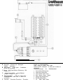
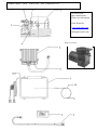
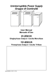
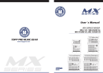
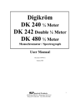
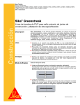
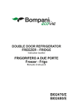
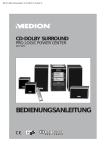
~INSTALLATION
AND SERVICE MANUAL
. . . . . . . . . . . . . . . . . . . . . . . . . . . . . . . . . . . . . . . . . . . . .. . . . . . . . . . . . . . . . . . . . . . . . . . . . . . . . . . . . . . . . . . . . . . . . . . . . . . . . . . . . . . .
.
ISOTHERM 4000/5000 W is a modern cooling system for yachts and power boats, using a holding
plate for storing the cold energy together with an electronic system, which automatically starts the
refrigeration compressor as soon as the engine is running. A large cooling capacity is achieved
while at the same time consuming the lowest possible electrical power. The installation is very
simple as nothing needs to be connected to the engine nor to the engine cooling water system.
~To achieve maximum efficiency and trouble-free operation, the following points are of vital
importance:
A well-insulated ice box is the most important factor for refrigeration efficiency. A
top-opening box is better than a front-opening fridge. Expanded or cross-linked PVC or
polyurethane material should be used as insulation.
~Recommended
insulation thickness:
Boxes 35-75 litres (l-3 cft) volume
Boxes over 75 litres (over 3 cft) volume
~50 mm (2”)
75-l 00 mm (3-4”)
The boxes should be fitted with a partition, preferrably adjustable,to
create a separate space
close to the holding plate for freezing. This should not be larger than needed. A
tight fitting lid and partition together with good insulation minimizes thermal leakage and
keeps the cold in the holding plate longer stored.
It isalso important that the electrical system is in good condition, especially when refrigeration is required for several days without the engine running. Try to estimate the total need
onboard for battery capacity. The engine should always have a separate starting battery. A
marine battery of 70 Amp. hours should be suitable for the cooling unit plus additional for
otherelectrical consumption onboard.
How the ice box is used is also important. Do not put in or take out articles more than
necessary and do not have them out of the fridge too long after cooking or having your meal.
Thermally it is very uneconomical to stow warm food. A good idea is to use an insulated bag
to carry froozen food from home or the shops. This will save battery power. Also, let the
engine run a few minutes extra when entering or leaving harbour, as running engine always
gives an extra supply of “free” cold.
~MAIN COMPONENTS
COMPRESSOR
The compressor in the ISOTHERM 5000W is of a new highly efficient type. A control box monitors
and controls its running conditions. The control box is designed for use in the toughest
environmental condtions, and is constructed by using the latest microprocessor technology. It
includes high and low voltage protection, polarity protection and a system which ensures a safe
compressor start. The compressor unit includes a seawater cooled heat exhanger (condenser),
made of a saltwater resistant material. An electrical seawater pump ensures effective cooling during
the warmest conditions. This guarantees highest efficiency. The seawater pump is noiseless and
of the diaphagm type for optimum life and is also self-priming so that it can be installed above the
water line.
~HOLDING PLATE
~The holding plates are made of the highest quality stainless steel. A thermisotor, fitted to the rear of
the holding plate, sends temperature information to the system control box. The holding plate is
easy to fit in the ice box, and may be fitted in any position - either vertical or horizontal.
$HORE POWER
The availability of 11 O/220 V main power is becoming more and more common in modern marinas.
ISOTHERM is especially suited for shore power. By connecting a good battery charger (min 20 A)
to the batteries, these will first be charged to their maximum capacity. When the batteries are fully
charged, their voltage will increase which the ISOTHERM control box registers. The compressor
then starts automatically, and runs continuously until the holding plate is completely frozen out. So
when you leave the marina, both the batteries and the cooling plate are “fully carged”. With some
new types of battery charger, that is floating around 13 volt, switch the control panel to “Freeze”
position.
for cooling the box ISOTHERM will always use the cool stored in the holding plate first, and only
when this is used start the compressor for a few minutes in the “economy program”. ISOTHERM is
almost noiseless, and its operating life so long that it may be left running continuously when shore
power is available.
QUICK COUPLINGS
The quick couplings simplify the connection of the holding plate copper tubing to the compresor
unit. The system is prefilled with Freon, and the quick couplings may be taken apart again without
the gas leaking out, if for some reason the ISOHERM unit must be removed. To make the
installation easy in larger yachts, the tinned tubes are 3 m (9ft.) long for 4000/45OOW and 3,5 m (11
ft.) for 5000W.
4
INSTRUCTIONS
First decide where the various units are best installed. Choose a suitable space for the compressor
that can be reached by 3,0/3,5 m copper pipes. This should be positioned so that no sharp bends are
required. The space for the compressor unit should not be at a position which can be higher than 2
(65 ft.)metres above waterline. The space choosen should also be easily reached with electric wire of
sufficient area. The electronic control unit must be positioned within 0,5 m (1,6 ft.) of the compressor.
The control panel must be placed so it can be reached by two wires: one from the freezer unit and one
from the electronic control unit. (For 5000W also with voltage sensor cable).
~The compressor unit and the electronic control unit are designed to withstand a marine environment
but should obviously be placed in as dry and protected surrounding as possible and with their
electrical connections downwards.
The holding plate position in the ice box should be choosen after considering the route for the
copper piping, the partition wall, etc.
Only regular hand tools are required for installation. If possible, drill the holes for the copper pipe
couplings with a 30 mm (1 t/4”) diam. holesaw. A power wire of suitable diameter and length, screws,
etc. are the only additional components required.
~HOLDING PLATE
If the box to be used is already installed, inspect it to establish the quality of its insulation as this is an
important factor concerning thermal efficiency.
The holding plate can be placed in any position. The copper pipe is annealed and can easily be bent
over the edge of the freezer so that the exit hole can be positioned behind. The four supports give
sufficient space for this to be done. Handle the copper pipe with care and bend carefully to avoid
creasing it. Use a cylindrical object if shapt bends are required. Be particularly careful with the thin
capillary pipe and its coupling at the other end of the copper pipe. The pipes are filled with Freon, a
gas which is completely safe in all respects, and these must not be cut or disconnected after
assembly. Start by unrolling the pipe to its full extend. Installation of the holding plate is easier if
someone can assist: One holds the freezer and directs the pipe through the side of the box while the
other feeds the pipe and its two connections through bulkheads, etc.
The holding plaate should be placed high in the box, approx. 100 mm (4”) below the top so that the
cold air can “fall” into the box. Holes for the pipe and couplings should be drilled to 28-30 mm diam.
The hole in the box should be as high up as possible to minimize leakage of cold air. Fill the hole
afterwards with insulating material. Any excess pipe should be coiled and fastened to a suitable
bulkhead or similar to avoid vibrating.
-5
~PARTITION FOR ADJUSTING TEMPERATURE
Cold air from the freezer unit sinks down to the bottom of the box. The box therefore needs a separate
space to enable it to be used as a freezer compartment. To achieve best results this compartement
should be no larger than absolutely necessary (max. 30 litres), The dividing partition should rest
against the sides of the box and have the same height as almost the top of the freezer unit. It should
have an adjustable gas of some millimetres (l/l 6 in.) at the lower edge to allow a suitable amount of
cold air to run into the cool section of the box, where a temperature of +4 to +lO “C (40-50 OF) can be
maintained. The dividing partition need not to be insulated, be easy to clean and preferably
transparent. Plexiglass is a suitable material.
tOMPRESSOR
UNIT
The compressor unit can be fitted in a suitable space such as a cupboard, locker, stowage compartment or even high (max. 2 m, 6 ft.) in the bilges of a large, dry boat. It may be beneficial to fit the unit on
two strong 90” angle brackets (available as accessories no. 30012) or on a shelf fitted to a bulkhead so
as not to loose valuable stowage space, etc. The unit will operate continuously at angles of up to
approx. 30 o and should therefore be fitted horizontally across the beam of sailing boats so as not to
exceed this at full angle of heal. The unit should be attached well to withstand excessive movements.
cleave the protection caps on until it is time to connect the quick couplings. Save the protection caps
for future use. The brass screw couplings should be connected and tightened quickly and smoothly
so that they first reach their sealing position before the membrane inside is opened. The couplings
can be unscrewed after this operation without gas leak ing out. Use two spanners 24 mm for this
operating so that the couplings will be carefully and very hard tightened. Be careful so that the female
coupling on the thin pipe does not rotate.
It can often’simplify assembly if the screw couplings are tightened before the compressor unit is
installed in its final position.
~The electronic control unit should be installed with the cables downwards, vertical and with the fuse
holder easily accessible.
~If the compressor unit has been fitted in a compartment that is used for other purposes, it may be
necessary to protect it from external damage in some way.
~WATER CONNECTION
~The water inlet is to be connected in a position to allow supply of cooling water to the unit even when
sailing6 Mount the compressor well protected but easy to reach and with its suction side connected to
the water inlet and its outlet connected to some water hull outlet.
6
tONTROL PANEL
~The control panel should be fitted where it is easily visible and within reach of the wires from both the
freezer and the compressor units, as well as voltage sensor cable for 5000W on ly (see below).
~To remove the panel from its cover, push the sides outwards so that the lips on each side are
released. Carefully lift out the panel and circuit board by holding the switch. Drill 4 small holes in each
corner for screws to fasten the box in position. Drill holes diamii 15 mm (l/2”) in all bulkheads , panels,
etc. for the wires and their connectors. It possible to take out the wires downwards if you cut a slit in the
bottom of the plastic box.
WIRERING
Carefully plug all the wires connectors into the circuit board. Replace the panel. Fasten the cables in
such a way that the connectors will not be damaged.
~The wires from the battery should be of a sufficient area in comparison to the length. A good guide to
use is:
2,5 m length:
4,0 m length:
6,0 m length:
4 mm2 (AWG #10-8ft.)
6 mm2
(AWG #KS - 1 2 ft.)
10 mm2 (AWG #6-20 ft.)
~They should be connected directly to the + and - poles of the battery, or better, main switch
(preferably by self-tapping screws and soldered wire terminals, etc.) . A good connection here is vital
for efficient operation of the system. Connect the + and - cables to the correct position on the control
unit.The fuse will cut if polarity is reversed by incorrect connections.
For 5000W you find an additional voltage sensor cable from control panel. This sensor cable should
be fitted to some “voltage representative” plus and minus connection, not on the same line as the
main power to compressor.
The control panel voltage sensor cable is to be connected to + and - at the switchboard panel or any
other suitable connection point by the 2-leads cable with open ends. White cable to -, brown to +.
~The 2-leads cable with a 2-pole connecting plug is connected to the electronic unit and to the
overheat cut-out. The thermisor is connected at the two tabs on the control panel.
~The system must not be connected directly to a battery charger without a battery connected in parallel.
SWAY OF OPERATING
When you put the control panel switch in “Economy” ISOTHERM operates to give a normal refrigerator temperature to minimum power output from batteries. The idea is that the compressor shall run
as much as possible when the engine is running and power supply is “free” and then store cooling
energy by charging the holding plate. When the engine is not running the compressor shall run as
m as possible and start first when all the cooling energy from holding plate is fully used. When
voltage is over 13,2 +/-0,2 volt (26,4+/-0,3 volt) the control panel “knows” that the engine is in
operation and stops the compressor at -15 “C and starts it again at -8°C. When voltage is under
12,6+/-0,2 volt (25,2+/-0,3 volt) it stops the compressor at -6°C and starts it again at -1 “C. The
melting/freezing point is then in the middle of above mentioned areas, i.e. at -7°C. That means when
voltage is over 13,2 volt (powered from engine/shore power), the compressor will freeze out the brain
in holding plate and make solid ice of it. When voltage is below 12,6 volt (powered from batteries) the
compressor will stop before it starts to make ice of the brain.
~If you put switch in “Freeze” the control panel think that the engine is running even it is not.
~TEST RUN
Set switch to “Normal-Auto” position. The green light will go on immediately and the yellow light after a
few minutes.This indicates that the compressor is running. A slight hissing noise will soon be heard
from the holding plate but frost will not appear on the plate after 15-30 minutes. Start the engine. After
a while (the exact time varies depending on the condition of the generator and battery) the indicator
lamps change: The yellow turns off and the red turns on.
When the engine is stopped the reverse will happen. The time it takes before this happens will again
depend on the condition of the battery and alternator. The greater the charge in the battery, the
longer the red light remains on. These conditions will occur as long as the holding plate has not
become really cold.
When the’unit is in “economy” mode but does not “ask” for more.cold the yellow lamp can be lighted
very weak.
wafter the test run, check all mechanical and electrical connections and fasten these to bulkheads, etc.
so that they are safe and secured.
No special maintenance is necessary. The unit can remain in the boat during winter but it is impo&rnt
to fill up waterpump and condenser with anti freeze mixture if risk for freezing temperature. Also keep
your batteries and electrical system in good condition. When necessary also clean the small filter on
the water inlet.
FAULT FINDING CHART
~POSSIBLE
~FAULT
CAUSE
FACTION
No power supply.
Is main switch on? Check fuse in
electronic control unit. Have power
wires been connected incorrectly?
Holding plate already sufficiently
cold. Control unit in blocking state.
Disconnect power for a few seconds.
Broken connections to temperature
sensor in freezer.
Check cable and connections.
Too low voltage in power supply
(under 10,5 V).
Check condition of battery.
3. Compressor and pump start and
stop when engine is running.
Voltage drop in electrical system.
Area of wires too small. Poor connections.
Alternator in poor condition or slipping
drive belt.
4. Compressor tries to start every
20 seconds. A weak hissing
noise will be heard always when it
tries to start.
Pump can not rotate or is faulty.
Check the pump and that power supply
is max. 1 ,O A /0,5 A. Area of wires is too
small.
5. Poor cooling effect. Compressor
runs too often.
Poor transfer of heat from compressor condenser.
Clean condenser
and hoses. Improve
water circulation.
Poor insulation of cold box.
Improve
Cooling
Check that quick couplings are properly tightened. Refill with cooling medium.
Freon according the sign on compressor,
1.
Nothing happens when
on. No lamps light.
switched
2. Compressor does not start.
Green lamp on.
medium
leakage.
insulation.
Insulate
cover.
Alternator in poor condition. Incorrectly adjusted charging relay.
Check charging rate. Compensate
battery splitting diodes if fitted.
Alternator does not come up to
speed.
Adjust or replace drive belt.
7. Compressor and pump continue
running after engine is stopped.
Battery voltage still high.
Normally a sign that batteries are in good
condition. Check that compressor stops
at 12,6 +I-0,2 V l25,4+1-0,3 V when cooling
plate frozen.
8. Frost on pipe to holding plate.
System slightly overfilled with
Freon.
Let out some Freon from service valve.
Pipe can be insulated or redirected inside
refrigerator.
6. No indication of “Freeze” on
control panel when engine starts.
for
A Styrsystem - Electronic unit -Steuergerat
B
C
D
E
F
Systeme
electronique
Manoverpanel
-Control panel - Schaltkasten Boitier de commande
Sakring 15A-Fuse15Amp.-Sicherung 15AFusible 15 A
Vattenpump-Water pump-Wasser
pumpe- Pompe ZI eau
Manoverpanelkabel
-Cable for control panel Schaltkastenkabel -Cable pour le boitier de
commande
Termistor -Thermistor-Thermistor -Thermistor
Fargkod for maniiverpanelkabel
Colour coding for control panel cable
Couleurs des fils electriques du cable pour le boitier de
commande
Farbkennzeichnungen
der
Schaltkastenkabel
1.
2.
3.
4.
5.
6.
7.
Gul-Yellow-Gelb-Jaune
Gr&-Grey-Grau-Gris
Gron-Green-Grfin-Vet-t
Brun - Brown - Braun - Marron
Rosa-Pink-Rosa-Rose
BH-Blue-Blau-Bleu
Vit - White- Weiss- Blanc
Scanned using OCR
May contain some errors
– Use with caution-
Isotherm 5000W/5500W
Wiring diagram electronic box NIk TIl Part
no. 39519 - 12 Volt, 39520 - 24 Volt
Great Water, Inc.
www.great-water.com
[email protected]
Compressor connection
1. Blue
3. Black
2. Red
Cable area from electronic box to
battery: Less than 4 m (12 ft) : 6mm2
4 - 6 m (12 - 18 ft) : 10 mm2
Voltage sensor
Voltage sensor lead to be connected to the
electrical system, e.g. at the switchboard. Do not
connect to the same cables as the compressor
supply cables.
Temp. sensor on holding plate
Isotherm 5000W 5500W 1998 to 1994 MAC Compressor R-12
SCAN & OCR –
May contain errors –
Please use with caution.
Great Water Inc.
www.great-water.com
[email protected]
Pump !5-E 39510
Isotherm 5000W 5500W Parts
1a
=> SIN 5999 (1988
Great Water Inc.
wwww.great-water.com
- 1991)
1
Compressor unit including condenser, bracket,
Fuko quick couplings, excl. electronic unit.
1b
SIN 6000 => (1992 - 1994)
Compressor unit including condenser, bracket,
Aeroquip quick couplings, excl. electronic unit.
12 Volt: 39501
24 Volt: 39502
1
12 Volt: 39501
12 Volt: 39502
2
Electronic unit 70 Hz
1
12 Volt: 39519
24 Volt: 39520
3
Holding plate
1
5001W/5002W:
39506 (355x280)
5501W/5502W:
39537 (400x320)
4
Resistance for waterpump, only for 24 Volt
1
39512
5
Water pump
1
39510
6
Water filter
1
39518
7
Zinc anode WI
1
39536
8
Control panel
1
12 Volt: 39508
24 Volt: 39509
39514
9
Controle cable
1
10
Temperature sensor with cable 2.5 m
1
39008
Main fuse
1
12 V/50 A: 39521
11.
24 V/30 A: 39522
12
Connection pipe complete with AQ couplings
1
39017
13
Connection pipe complete with Fuko couplings
1
39018