1
Service Manual
EIP 2
V 1.0.x
V 1.1.x
ERBE
EIP 2
11.14
Service Manual
EIP 2
Registered trademarks of ERBE Elektromedizin GmbH: APC®, APC 300®, AUTO CUT®, AUTOCUT®, BICISION®,
BiClamp®, CLASSIC COAG®, CLASSIC CUT®, CLEVERCAP®, DeCo®, DRYCUT®, ENDO CUT®, ENDOCOAG®, ENDOCUT®,
ERBE®, ERBE logo (design mark), ERBECRYO®, ERBEFLO®, ERBEJET®, ERBELift®, ERBOKRYO®, FIAPC®, FORCEDAPC®,
Hybrid knife®, HybridKnife®, Hydro-Jet®, ICC 200®, ICC 80®, NESSY®, NESSY Ω®, PRECISE APC®, PRECISEAPC®,
Preflow®, PULSEDAPC®, ReMode®, REMODE®, SWIFT COAG®, SWIFTCOAG®, The Color Blue®, TWIN COAG®, VIO®.
Service Manual Art.-No. 80116-261
All rights to this manual, in particular rights of duplication, dissemination and translation, are reserved. No part of this
manual may be reproduced in any form (by photocopying, microfilming or other methods) or processed, duplicated or
disseminated by the use of electronic systems without the written consent of ERBE Elektromedizin GmbH.
The information contained in this manual may be amended or supplemented without prior notice and represents no obligation on the part of ERBE Elektromedizin GmbH.
Printed by ERBE Elektromedizin
Printed in Germany
Copyright © ERBE Elektromedizin GmbH, Tübingen 2014
Table of Contents
Table of Contents
1
Safety information. . . . . . . . . . . . . . . . . . . . . . . . . . . . . . . . . . . . 7
Classification of the safety information . . . . . . . . . . . . . . . . . . . . . . . . . . . . . . .7
Knowledge of the User Manual . . . . . . . . . . . . . . . . . . . . . . . . . . . . . . . . . . . .7
Protection from the risk of electric shock . . . . . . . . . . . . . . . . . . . . . . . . . . . . .7
Electrostatically sensitive components. . . . . . . . . . . . . . . . . . . . . . . . . . . . . . . .8
Liability and warranty . . . . . . . . . . . . . . . . . . . . . . . . . . . . . . . . . . . . . . . . . . . .8
2
Modifications. . . . . . . . . . . . . . . . . . . . . . . . . . . . . . . . . . . . . . . . 9
3
Unit description . . . . . . . . . . . . . . . . . . . . . . . . . . . . . . . . . . . . . 11
Unit variants . . . . . . . . . . . . . . . . . . . . . . . . . . . . . . . . . . . . . . . . . . . . . . . . . .11
Factory setting . . . . . . . . . . . . . . . . . . . . . . . . . . . . . . . . . . . . . . . . . . . . . . . .11
80116-261
11.14
Controls . . . . . . . . . . . . . . . . . . . . . . . . . . . . . . . . . . . . . . . . . . . . . . . . . . . . .12
Controls at the front . . . . . . . . . . . . . . . . . . . . . . . . . . . . . . . . . . . . . . . . . 12
Symbols . . . . . . . . . . . . . . . . . . . . . . . . . . . . . . . . . . . . . . . . . . . . . . . . . . 13
Controls at the rear . . . . . . . . . . . . . . . . . . . . . . . . . . . . . . . . . . . . . . . . . . 13
Description of function . . . . . . . . . . . . . . . . . . . . . . . . . . . . . . . . . . . . . . . . . .14
4
Technical Data . . . . . . . . . . . . . . . . . . . . . . . . . . . . . . . . . . . . . . 15
5
Installation. . . . . . . . . . . . . . . . . . . . . . . . . . . . . . . . . . . . . . . . . 17
Installation possibilities . . . . . . . . . . . . . . . . . . . . . . . . . . . . . . . . . . . . . . . . . .17
6
Circuit Descriptions . . . . . . . . . . . . . . . . . . . . . . . . . . . . . . . . . . 19
Block diagram EIP 2 (120 V / 230 V) . . . . . . . . . . . . . . . . . . . . . . . . . . . . . . . .20
Block diagram EIP 2 (100 V) . . . . . . . . . . . . . . . . . . . . . . . . . . . . . . . . . . . . . .21
Beschreibung der einzelnen Baugruppen . . . . . . . . . . . . . . . . . . . . . . . . . . . .22
Line input . . . . . . . . . . . . . . . . . . . . . . . . . . . . . . . . . . . . . . . . . . . . . . . . . 22
Transformer. . . . . . . . . . . . . . . . . . . . . . . . . . . . . . . . . . . . . . . . . . . . . . . . 22
Bridge-connected rectifier . . . . . . . . . . . . . . . . . . . . . . . . . . . . . . . . . . . . . 22
Switching controller . . . . . . . . . . . . . . . . . . . . . . . . . . . . . . . . . . . . . . . . . 22
Monitoring the motor control . . . . . . . . . . . . . . . . . . . . . . . . . . . . . . . . . 22
Motor control . . . . . . . . . . . . . . . . . . . . . . . . . . . . . . . . . . . . . . . . . . . . . . 22
Microcontroller . . . . . . . . . . . . . . . . . . . . . . . . . . . . . . . . . . . . . . . . . . . . . 23
CAN module (optional) . . . . . . . . . . . . . . . . . . . . . . . . . . . . . . . . . . . . . . . 23
Footswitch . . . . . . . . . . . . . . . . . . . . . . . . . . . . . . . . . . . . . . . . . . . . . . . . 23
Control panel . . . . . . . . . . . . . . . . . . . . . . . . . . . . . . . . . . . . . . . . . . . . . . 23
Motor . . . . . . . . . . . . . . . . . . . . . . . . . . . . . . . . . . . . . . . . . . . . . . . . . . . . 23
5 / 56
Table of Contents
7
Service programs . . . . . . . . . . . . . . . . . . . . . . . . . . . . . . . . . . . . 25
Calling up service program mode . . . . . . . . . . . . . . . . . . . . . . . . . . . . . . . . . . 25
Navigating between service programs . . . . . . . . . . . . . . . . . . . . . . . . . . . . . . 25
Leaving the service program mode . . . . . . . . . . . . . . . . . . . . . . . . . . . . . . . . . 25
Description of service programs . . . . . . . . . . . . . . . . . . . . . . . . . . . . . . . . . . . 26
Service program S1 Flow test. . . . . . . . . . . . . . . . . . . . . . . . . . . . . . . . . . . 26
Service program S2 LED Test . . . . . . . . . . . . . . . . . . . . . . . . . . . . . . . . . . . 27
Service program S3 Continuous running / Burn-In . . . . . . . . . . . . . . . . . . . 28
Service program S4 Version output . . . . . . . . . . . . . . . . . . . . . . . . . . . . . . 29
Service program S5 Automatic pressure control. . . . . . . . . . . . . . . . . . . . . 30
8
Remedying malfunctions . . . . . . . . . . . . . . . . . . . . . . . . . . . . . . 31
9
Maintenance and servicing . . . . . . . . . . . . . . . . . . . . . . . . . . . . 33
Technical safety check, national regulations, trained persons . . . . . . . . . . . . . 33
Test intervals . . . . . . . . . . . . . . . . . . . . . . . . . . . . . . . . . . . . . . . . . . . . . . . . . 33
Technical safety check . . . . . . . . . . . . . . . . . . . . . . . . . . . . . . . . . . . . . . . . . . 34
Important information. . . . . . . . . . . . . . . . . . . . . . . . . . . . . . . . . . . . . . . . 34
User manual and visual inspections . . . . . . . . . . . . . . . . . . . . . . . . . . . . . . 35
Tests to be conducted in accordance with the national specifications
and regulations . . . . . . . . . . . . . . . . . . . . . . . . . . . . . . . . . . . . . . . . . . . . . 35
Performance tests . . . . . . . . . . . . . . . . . . . . . . . . . . . . . . . . . . . . . . . . . . . 35
10 Replacing components . . . . . . . . . . . . . . . . . . . . . . . . . . . . . . . 37
Change pump head . . . . . . . . . . . . . . . . . . . . . . . . . . . . . . . . . . . . . . . . . . . . 37
Change main board . . . . . . . . . . . . . . . . . . . . . . . . . . . . . . . . . . . . . . . . . . . . 44
11 Spare parts . . . . . . . . . . . . . . . . . . . . . . . . . . . . . . . . . . . . . . . . 47
Abbreviations . . . . . . . . . . . . . . . . . . . . . . . . . . . . . . . . . . . . . . . . . . . . . . . . . 47
EIP 2 without ECB . . . . . . . . . . . . . . . . . . . . . . . . . . . . . . . . . . . . . . . . . . . . . 48
EIP 2 with ECB . . . . . . . . . . . . . . . . . . . . . . . . . . . . . . . . . . . . . . . . . . . . . . . . 52
6 / 56
80116-261
11.14
Change gear motor . . . . . . . . . . . . . . . . . . . . . . . . . . . . . . . . . . . . . . . . . . . . 39
1 • Safety information
CHAPTER 1
Safety information
Classification of the safety information
WARNING!
CAUTION!
ATTENTION!
IMPORTANT!
The WARNING! safety indication refers to a risk of personal injury.
The CAUTION! safety indication refers to a risk of damage to property.
The ATTENTION! safety indication refers to a risk which can cause
equipment to become unserviceable.
The IMPORTANT! designation indicates application information and
other particularly important information.
Knowledge of the User Manual
80116-261
11.14
The User Manual for this unit constitutes an integral part of this Service
Manual. For performing servicing activities it is assumed that the reader
has knowledge of the User Manual, especially procedures for installation,
putting into operation, and handling.
Protection from the risk of electric shock
WARNING!
The supply voltage must match the voltage specified on the rating
plate. Connect the unit / the equipment cart to a properly installed
grounded outlet. Only use the ERBE power cord or an equivalent
power cord for this purpose. The power cord must bear the national
test symbol.
For safety reasons, multiple outlets and extension cords should not be
used. If their use is unavoidable, they also must be provided with
proper grounding.
WARNING!
Unplug the power cord from the outlet before exchanging parts of the
unit or cleaning it.
WARNING!
Do not plug a wet power cord into the unit or into an outlet.
7 / 56
1 • Safety information
WARNING!
Do not touch any unprotected wires or conductive surfaces while the
unit is opened and under voltage.
WARNING!
Blown line fuses may only be replaced by a competent technician.
Only replacement fuses of the rating specified on the unit's name
plate may be used. Before resuming operation the unit must be subjected to a performance test by a competent technician.
Electrostatically sensitive components
CAUTION!
This unit contains electrostatically sensitive components. Work at an
anti-static workplace while repairing the unit. Wear a grounding armband while working with electrostatically sensitive components. Hold
the circuit boards by their non-conducting corners. Use an anti-static
container for transporting electrostatically sensitive components and
the circuit boards.
Liability and warranty
Adjustments, tests, modifications, maintenance and repair work may
only be performed by ERBE or persons trained by ERBE. If the work is
not performed by trained persons, ERBE accepts no liability and warranty rights become void.
It is recommended that the technical safety check also be performed
by ERBE or persons trained by ERBE.
ATTENTION!
8 / 56
Only use original ERBE spare parts. The manufacturer accepts no liability and the warranty rights becomes void if original spare parts are not
used.
80116-261
11.14
ATTENTION!
2 • Modifications
CHAPTER 2
Modifications
From V 1.1.x
Hardware
No changes
Software
Component affected
Service programs
Description of the modification
New Service program:
80116-261
11.14
S 5 Automatic pressure control
9 / 56
80116-261
11.14
2 • Modifications
10 / 56
3 • Unit description
CHAPTER 3
Unit description
Unit variants
The EIP 2 (ERBE Irrigation Pump) is available in the following unit variants:
•
•
•
•
•
230
230
120
100
100
V with ECB socket 1
V without ECB socket
V without ECB socket
V with ECB socket
V without ECB socket
Factory setting
The EIP 2 has the following settings when it is delivered by the manufacturer:
Quick activation button I = 30% 2
Quick activation button II = 50%
Quick activation button III = 80%
Automatic pressure control activated
for units up to software version 1.0.0
• Automatic pressure control deactivated
(for units from software version 1.1.0)
80116-261
11.14
•
•
•
•
IMPORTANT!
Once settings have been changed and saved they still apply even after
the unit has been restarted. A reset (= switching the unit back to the
factory setting) is not possible.
1. ECB = ERBE Communication Bus for connecting the EIP 2 to a VIO electrosurgical unit.
2. Flow in % relative to the maximum flow of 500 ml/min.
11
/ 56
3 • Unit description
Controls
IMPORTANT!
This chapter contains an overview of the controls of the unit(s). The
relevant User Manual for the unit(s), knowledge of which is assumed
for servicing work, provides detailed information about how to use
the unit(s).
80116-261
11.14
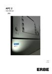
Controls at the front
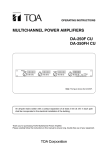
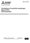
Fig. 3-1
1
Power switch
2
Quick activation button I (30 % of capacity1 / approx. 150 ml/min)
3
Quick activation button II (50 % of capacity / approx. 250 ml/min)
4
Quick activation button III (80 % of capacity / approx. 400 ml/min)
5
Flow display
6
Up / Down buttons
7
Activation button
8
Pump head lid
9
Direction arrow for irrigation liquid
1. Flow in % relative to the maximum flow of 500 ml/min.
12 / 56
3 • Unit description
Symbols
Read User Manual.
The unit meets the requirements of Type CF and is protected against the
effects of a defibrillator discharge.
Never place your fingers in the pump head.
80116-261
11.14
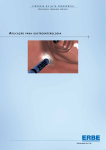
Controls at the rear
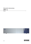
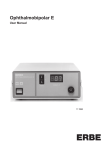
Fig. 3-2
1
Optional ECB socket (ECB = ERBE Communication Bus) for connecting
the EIP 2 to a VIO electrosurgical unit
2
Footswitch socket
3
Potential equalization
4
Power connection
5
Power fuse
13
/ 56
3 • Unit description
Description of function
The EIP 2 (ERBE Irrigation Pump) is a peristaltic pump. This operating principle is based on pressing or squeezing a flexible pump hose at one or
more points and on movement of the squeezed point in the desired direction of liquid flow. For this reason peristaltic pumps are sometimes referred to as peristaltic squeeze pumps. Movement of the squeezed point
is accomplished with the aid of a pump rotor that has rollers around its
perimeter. Flow is determined by rotor speed (speed of motion of the
squeezed point) and internal cross-section of the hose.
Advantages of peristaltic
pumps
With peristaltic pumps the medium and the pump do not come into contact with one another. Therefore peristaltic pumps are particularly suited
for metering a very wide range of media. As opposed to other types of
pump like diaphragm pumps, with peristaltic pumps it is very easy to
adapt the material of the pump hose, or components coming into contact with the medium, to the product being pumped. A pump hose is selected and used that is chemically suited for the product being pumped
("milled hose").
80116-261
11.14
Peristaltic pump principle
14 / 56
4 • Technical Data
CHAPTER 4
Technical Data
Power supply for devices with 230 V
Nominal line voltage
Line current
Power fuse
Nominal line frequency
230 V ± 10%
200 mA
T 0.2 A
50 / 60 Hz
Power input in Standby Mode
5W
Power input at max. irrigation flow
20 W
Potential equalization terminal
Yes
80116-261
11.14
Power supply for devices with 120 V
Nominal line voltage
Line current
Power fuse
Nominal line frequency
120 V ± 10%
400 mA
T 0.4 A
50 / 60 Hz
Power input in Standby Mode
3W
Power input at max. irrigation flow
20 W
Potential equalization terminal
Yes
Power supply for devices with 100 V
Nominal line voltage
Line current
Power fuse
Nominal line frequency
100 V ± 10 %
315 mA
T 0.315 A
50 / 60 Hz
Power input in Standby Mode
3W
Power input at max. irrigation flow
20 W
Potential equalization terminal
Yes
Operating mode
Continuous duty
Yes
15
/ 56
4 • Technical Data
Dimensions and weight
Width x height x depth
205 x 125 x 170 mm (without pump head)
Width x height x depth
205 x 125 x 210 mm (with pump head)
Weight
3 kg
Ambient conditions for transport and storage of unit
Temperature
-40 °C to + 70 °C
Relative humidity
10% – 95%
Ambient conditions for operation of unit
Temperature
+10 °C to + 40 °C
Relative humidity
15% – 80%, noncondensing
If the unit has been stored or transported at temperatures below +10 °C or above +40 °C, the unit will
require approx. 3 hours to acclimatize at room temperature.
Standards
Classification according to EC Directive 93/42/EEC
II a
Protection class as per EN 60 601-1
I
Type as per EN 60 601-1
CF
16 / 56
80116-261
11.14
Acclimatizing
5 • Installation
CHAPTER 5
Installation
Installation possibilities
For EIP 2 (ERBE Irrigation Pump) there are three installation possibilities:
• Installation on an ERBE VIO Cart.
• Installation on an ERBE Universal Cart.
• EIP 2 as a stand alone variant.
80116-261
11.14
These installation possibilities are described in the User Manual for the
EIP 2 and the User Manuals for the above equipment carts.
17
/ 56
80116-261
11.14
5 • Installation
18 / 56
6 • Circuit Descriptions
CHAPTER 6
80116-261
11.14
Circuit Descriptions
19
/ 56
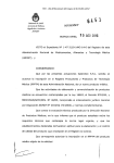
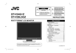
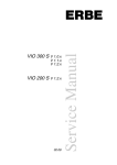
Fig. 6-1
20 / 56
ECB2
ECB1
CAN module
( optional )
120 V
230 V
Mainboard
DC
5V
DC
Switching
controller
Transformer
80116-261
11.14
24V
2 x 9V
1,33A
DC
5V
Motor
control
(PWM)
Microcontroller
24V
Control panel
Monitoring
the
motor
control
AC
Bridgeconnected
rectifier
U-Motor
I-Motor
Line input
M
Motor
6 • Circuit Descriptions
Block diagram EIP 2 (120 V / 230 V)
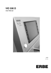
U-Motor
ECB ERBE Communication Bus
ECB2
ECB1
CAN module
(optional)
100 V
Line input
Mainboard
DC
5V
DC
Switching
controller
Transformer
24V
2 x 12V
1,25A
DC
Motor
control
(PWM)
Microcontroller
24V
Control panel
5V
Monitoring
the
motor
control
AC
Bridgeconnected
rectifier
U-Motor
I-Motor
80116-261
11.14
M
Motor
6 • Circuit Descriptions
Block diagram EIP 2 (100 V)
Fig. 6-2
21
/ 56
U-Motor
ECB ERBE Communication Bus
6 • Circuit Descriptions
Description of the various assemblies
Line input
The EIP 2 can be operated on line voltages of 230 V, 120 V, or 100 V.
First of all the appropriate figure must be set, ±10 %, in the window of
the voltage selector switch on the main board.
CAUTION!
An incorrect setting can cause damage to the unit.
Transformer
The transformer converts the line voltage input from 230 V ±10 % or
120 V ±10 % to 2 x 9 V. The maximum available current is 1.33 A.
For operation of the EIP 2 at a line voltage of 100 V ±10 % a different
type of transformer must be used. That transformer converts the line voltage input to 2 x 12 V um. The maximum available current is 1.25 A.
Bridge-connected rectifier
Switching controller
The switching controller provides an operating voltage of 5 V.
Monitoring the motor control
This circuit is designed to prevent a faulty motor control from leading to
uncontrolled pump activity. The operating voltage of 24 V is only supplied to the motor control if the microcontroller releases it by actuating
the monitoring circuit accordingly.
Motor control
The motor control is regulated by the microcontroller via a PWM signal
at a level of 5 V. The output voltage of the motor control is increased to
a maximum of 24 V depending on the PWM signal.
22 / 56
80116-261
11.14
The bridge-connected rectifier provides the operating voltage of 24 V.
6 • Circuit Descriptions
Microcontroller
The Type PIC18F258 microcontroller handles several tasks:
• Evaluation of current and voltage measurements of motor monitoring
• Adjustment of motor control to the current and voltage levels via a
PWM signal
• Checking of any activations by pushbutton or footswitch
• Updating of display on the control panel
• Communication via a CAN interface with the VIO electrosurgical unit
(only on units with ECB socket, ECB = ERBE Communication Bus).
CAN module (optional)
The CAN module enables communication between EIP 2 and the VIO
electrosurgical unit.
Footswitch
The pump can be activated with the EIP 2 footswitch.
Control panel
80116-261
11.14
The control panel makes it possible for the user to perform settings on
the EIP 2.
Three so-called quick activation buttons enable direct adjustment of the
setting, which is otherwise performed using the Up and Down buttons.
The pump can be started with the activation button.
The display section on the control panel is comprised of three 7-segment
displays, which are updated constantly by the microcontroller.
Motor
The motor is a DC motor with a nominal voltage of 24 V and a nominal
current of 1.1 A.
The motor has a flanged gear unit, via which the pump head is driven.
23
/ 56
80116-261
11.14
6 • Circuit Descriptions
24 / 56
7 • Service programs
CHAPTER 7
Service programs
Calling up service program mode
When switching on the unit hold down the up / down buttons.
On units with an ECB socket (ECB = ERBE Communication Bus) the service
programs can be called up either by pressing the above button combination or via CAN-ID.
Navigating between service programs
As soon as the unit is in service program mode, you can toggle between
the various service programs S1 – S5 using the up / down buttons.
80116-261
11.14
Leaving the service program mode
Hold down the up / down buttons until the display shows
.
The unit performs a program reset and starts up again in operating mode.
25
/ 56
7 • Service programs
Description of service programs
Service program S1 Flow test
Description
The S1 service program is used to check the flow of irrigation liquid over
a period of 1 minute at a flow setting of 100 %.
If the service program ends successfully, the message "CS1" (Complete
Service Program 1) is output on the display. If a fault occurs during execution, the message "ES1" (Error Service Program 1) is displayed.
Both messages can be canceled by pressing the activation button.
If a fault occurs during execution, its cause can be localized in operating
mode. To do this, abort the service program. The unit then automatically
switches to operating mode and the display shows an error message.
Run time
1 minute.
Fixed at 100 %.
To activate the service program
Press the activation button.
To abort the service program
Press quick activation button III.
26 / 56
80116-261
11.14
Set value
7 • Service programs
Service program S2 LED Test
Description
Service program S2 is used to check correct operation of all the LEDs on
the control panel.
Run time
Not limited.
Set value
Not applicable.
To activate the service program
Press the activation button.
To abort the service program
80116-261
11.14
Press quick activation button III.
27
/ 56
7 • Service programs
Service program S3 Continuous running / Burn-In
Description
Service program S3 checks whether EIP 2 can withstand a substantial
continuous load.
If the service program ends successfully, the message "CS3" (Complete
Service Program 3) is output on the display. If a fault occurs during execution, the message "ES3" (Error Service Program 3) appears.
Both messages can be canceled by pressing the activation button.
If a fault occurs during execution, its cause can be localized in operating
mode. To do this, abort the service program. The unit then automatically
switches to operating mode and the display shows an error message.
Run time
10 minutes.
Set value
Fixed at 80 %.
Press the activation button.
To abort the service program
Press quick activation button III.
28 / 56
80116-261
11.14
To activate the service program
7 • Service programs
Service program S4 Version output
Description
Service program S4 indicates the software version of EIP 2.
Run time
Not limited.
Set value
Not applicable.
To activate the service program
Press the activation button.
To abort the service program
80116-261
11.14
Press quick activation button III.
29
/ 56
7 • Service programs
Service program S5 Automatic pressure control
Availability
From software version 1.1.0.
Description
The automatic pressure control of the EIP 2 can be activated and deactivated with service program S5.
Run time
Not limited.
Set value
When service program S5 is activated, a selection can be made between
the following settings with the up / down buttons:
Display S50: Automatic pressure control deactivated.
Display S51: Automatic pressure control activated.
To activate the service program
Press the activation button.
To abort the service program
Press quick activation button III.
30 / 56
80116-261
11.14
The internal EEPROM of the PIC18 automatically saves the setting selected.
8 • Remedying malfunctions
CHAPTER 8
80116-261
11.14
Remedying malfunctions
WARNING!
Unplug the power cord from the outlet before exchanging parts of the
unit or cleaning it.
ATTENTION!
Adjustments, technical tests, modifications, maintenance and repair
work may only be performed by ERBE or persons trained by ERBE. If
the work is not performed by trained persons, ERBE accepts no liability
and warranty rights become void.
Error
Possible cause
Remedy
The set value flashes and the
pump is deactivated.
Time out error. The activation
time of t < 20 s was exceeded.
Terminate present activation.
Then re-activate the pump.
The pump lid symbol (- n -)
flashes and the pump cannot be
activated or the already activated
pump is deactivated.
The pump lid was not closed
before activation of the pump.
Close pump lid.
The pump lid was opened with
the pump activated.
Close pump lid.
Display E 1
Motor control faulty.
Change main board,
see page 44.
Display E 2
Motor current exceeds the permissible limit. Pump head faulty
or damaged.
Check pump head to make sure it
is fitted properly.
Change pump head if it is faulty,
see page 37.
Motor current exceeds the permissible limit. Gear motor faulty
or damaged.
Change gear motor,
see page 39.
No measurable current flow. The
connection between the gear
motor and the main board was
interrupted.
Restore connection between
gear motor and main board.
No measurable current flow.
Gear motor faulty.
Change gear motor,
see page 39.
No measurable current flow. Current measurement gain has
failed.
Change main board,
see page 44.
Monitoring circuit of motor control faulty.
Change main board,
see page 44.
Display E 3
Display E 4
31
/ 56
8 • Remedying malfunctions
Possible cause
Remedy
Display E 5
CRC Check faulty. Due to various
influences such as ageing or radiation the memory of the PIC may
be altered.
Change main board,
see page 44.
Display L 1
A quick activation button was
programmed with flow that is
too low or too high.
Observe programming rules for
quick activation buttons:
Flow on button
< flow on
button
Flow on button
< flow on
button
80116-261
11.14
Error
32 / 56
9 • Maintenance and servicing
CHAPTER 9
Maintenance and servicing
Technical safety check, national regulations,
trained persons
ATTENTION!
Adjustments, tests, modifications, maintenance and repair work may
only be performed by ERBE or persons trained by ERBE. If the work is
not performed by trained persons, ERBE accepts no liability and warranty rights become void.
It is recommended that the technical safety check also be performed
by ERBE or persons trained by ERBE.
IMPORTANT!
The safety check is a preventive measure in which there is examined
whether the equipment is safe and ready for operation. In order to
perform the tests the relevant specifications and regulations of the
particular country must be observed.
80116-261
11.14
Test intervals
IMPORTANT!
ERBE recommends performing a technical safety check after every
repair, but at least once a year.
33
/ 56
9 • Maintenance and servicing
Technical safety check
For simplification the device to be tested is referred to below as the "test
specimen".
34 / 56
WARNING!
For safety reasons (personnel protection) the test specimen should
generally be operated by a suitable isolating transformer.
An exceptional case is the tests for grounded conductor resistance,
ground leakage current, and patient leakage current, in which the test
specimen is supplied with current via the safety tester.
ATTENTION!
In the event of a fault occurring in the test specimen or individual
components during the technical safety check the test steps taken so
far no longer apply.
Remedy the defect and repeat the technical safety check from the
beginning.
IMPORTANT!
It is assumed that the user knows how to operate the test specimen,
the test equipment, the measuring equipment, and auxiliary test
equipment. The test instructions only apply in conjunction with the
relevant test steps.
IMPORTANT!
Test equipment, measuring equipment, and auxiliary test equipment
(cables, test boxes, etc.) are listed separately at the beginning of each
test unit. Where ERBE article numbers are specified, only original ERBE
test equipment, measuring equipment, and auxiliary test equipment
may be used.
IMPORTANT!
The test report for the technical safety check can be requested from
ERBE Technical Service Tübingen. For the address see address sheet on
last page.
80116-261
11.14
Important information
9 • Maintenance and servicing
User manual and visual inspections
• Test specimen and accessories (where enclosed) undamaged externally.
• User manual present.
• All labels on the test specimen (conformity declaration mark, rating
plate, and all wording) present and readily legible.
Tests to be conducted in accordance with the
national specifications and regulations
Grounded conductor test
Leakage current
measurement
• Ground terminal to chassis.
• Ground terminal to potential equalization pin.
•
•
•
•
Ground leakage current, normal condition (N.C.).
Ground leakage current, single-fault condition (S.F.C.).
Patient leakage current, normal condition (N.C.).
Patient leakage current, single-fault condition (S.F.C.).
Performance tests
Testing tools
80116-261
11.14
ERBE
Art.-No.
Designation
20325-000
Footswitch for EIP 2
20325-001
Tubing set ERBE EIP 2 (100 V, 230 V)
Test setup
• The test specimen is connected to the power supply via the power
cord.
Test procedure
Power switch
1. Check power switch for smooth operation. The power switch must
be easy to operate and must neither stick nor scrape.
2. Press power switch. The power switch must snap into the "ON"
position and the test specimen must perform a system start.
Control buttons
1. Check all the buttons on the control panel to make sure they are
operating properly. Press each button at least twice.
35
/ 56
7-segment displays and LEDs
1. Start test specimen in service program mode and select service program S2.
2. Test 7-segment displays: All the segments on the three 7-segment
displays should be an equally bright green color.
3. Test LEDs: The border of the activation button should be backlit in
yellow.
Deactivation when opening
the pump head / head sensor
1. Test step 1: Select 80 % flow on the test specimen. Hold down the
activation button and the pump motor will start up. Open the pump
head lid, keeping the activation button pressed. The pump motor
should stop.
2. Test step 2: With the pump lid open, activate the test specimen
using the activation button. The pump motor must not start up and
on the display a symbol similar to an "n" (= pump lid symbol) should
flash.
3. Test step 3: Connect up footswitch. Repeat test step 1, now activating the test specimen with the footswitch.
4. Test step 4: Repeat test step 2, now activating the test specimen
with the footswitch.
Automatic shutdown in the
event of continuous activation
1. Test step 1: Select 80 % flow on the test specimen and activate the
pump motor using the activation button. Activation should stop
within a time window of 18 s to 22 s.
2. Test step 2: Connect up footswitch. Repeat test step 1, now activating the test specimen with the footswitch. Activation should stop
within a time window of 18 s to 22 s.
Check the automatic
pressure control
IMPORTANT! For units from software version 1.1.0 onwards, the automatic pressure control can be optionally activated or deactivated (see service program S5). For this test, the automatic pressure control must be
activated.
1.
2.
3.
4.
Insert tube and fill with irrigation liquid (water).
To simulate a blockage, clamp the tube at the distal end.
Set pump flow to 100 %.
Activate pump motor using activation button (or footswitch) and
keep it activated. The test specicmen should reduce flow very audibly.
5. Undo the clamp on the tube. The test specicmen should increase
flow very audibly back to set pump flow.
6. Terminate activation.
36 / 56
80116-261
11.14
9 • Maintenance and servicing
10 • Replacing components
CHAPTER 10
Replacing components
Change pump head
WARNING!
Unplug the power cord from the outlet before exchanging parts of the
unit or cleaning it.
ATTENTION!
Adjustments, technical tests, modifications, maintenance and repair
work may only be performed by ERBE or persons trained by ERBE. If
the work is not performed by trained persons, ERBE accepts no liability
and warranty rights become void.
IMPORTANT!
Tools
Only use original replacement parts.
• Phillips screwdriver PH 1
80116-261
11.14
Remove pump head
1. Open pump head lid completely.
2. Undo screws (2).
3. Withdraw pump head toward the front.
37
/ 56
10 • Replacing components
4. Fit new pump head in reverse order.
38 / 56
80116-261
11.14
Fit new pump head
10 • Replacing components
Change gear motor
WARNING!
Unplug the power cord from the outlet before exchanging parts of the
unit or cleaning it.
ATTENTION!
Adjustments, technical tests, modifications, maintenance and repair
work may only be performed by ERBE or persons trained by ERBE. If
the work is not performed by trained persons, ERBE accepts no liability
and warranty rights become void.
IMPORTANT!
Tools
Only use original replacement parts.
• Phillips screwdriver PH 1 (short and long)
• Phillips screwdriver PH 2
• Box wrench size 7
80116-261
11.14
Remove pump head
1. Open pump head lid completely.
2. Undo screws (2).
3. Withdraw pump head toward the front.
39
/ 56
10 • Replacing components
Remove housing cover
4. Undo screws in the sub-base (2).
5. Undo screws in the rear panel (3).
6. Remove housing cover carefully, first upward and then to the rear.
40 / 56
80116-261
11.14
6
10 • Replacing components
Remove front frame
9
8
7
80116-261
11.14
7
7. Undo screws in the frame (2).
8. Loosen nut (1) in the housing bottom. The nut can be removed completely but does not have to be.
9. Pull away front frame toward the front as permitted by the display
connector (not illustrated).
41
/ 56
10 • Replacing components
J34
J35
J32
J31
J36
J10
10. Remove connectors J34, J35, and J10 from the main board and
remove the front frame completely toward the front.
42 / 56
80116-261
11.14
J31
10 • Replacing components
Change gear motor
11
80116-261
11.14
11. Undo screws on the gear motor (4) and remove the gear motor to
the rear.
12. Fit a new gear motor in reverse order.
13. Fit front frame in reverse order.
ATTENTION!
Check line voltage setting
The EIP 2 can be operated on a line voltage of 230 V, 120 V, or 100 V.
Therefore, every time the unit is opened always check afterwards
whether the correct line voltage ±10 % is set on the line voltage selector switch on the main board.
14. Close housing cover.
43
/ 56
10 • Replacing components
Change main board
WARNING!
Unplug the power cord from the outlet before exchanging parts of the
unit or cleaning it.
ATTENTION!
Adjustments, technical tests, modifications, maintenance and repair
work may only be performed by ERBE or persons trained by ERBE. If
the work is not performed by trained persons, ERBE accepts no liability
and warranty rights become void.
IMPORTANT!
Tools
Only use original replacement parts.
• Phillips screwdriver PH 1 (short and long)
• Phillips screwdriver PH 2
• Box wrench size 7
Remove housing cover
see page 40.
Remove front frame
see page 41.
80116-261
11.14
Change main board
J34
J35
J32
J31
J36
J10
J31
1. Remove connectors J32 and J36 from main board.
2. Only units with ECB socket ( ECB = ERBE Communication Bus) also
remove connector J31 from main board.
44 / 56
80116-261
11.14
10 • Replacing components
3. Undo nuts (4) and withdraw main board carefully.
4. Fit new main board in reverse order.
5. Fit front frame in reverse order.
ATTENTION!
Check line voltage setting
The EIP 2 can be operated on a line voltage of 230 V, 120 V, or 100 V.
Therefore, every time the unit is opened always check afterwards
whether the correct line voltage ±10 % is set on the line voltage selector switch on the main board.
6. Close housing cover.
45
/ 56
80116-261
11.14
10 • Replacing components
46 / 56
11 • Spare parts
CHAPTER 11
Spare parts
Abbreviations
80116-261
11.14
ECB = ERBE Communication Bus
47
/ 56
48 / 56
Fig. 11-1
80116-261
11.14
9a 9a 9a 9 a 9 a 9 a 7$
7$
9a 11 • Spare parts
EIP 2 without ECB
55000-116 (2)
80116-261
11.14
55000-116 (2)
55105-000 (1)
51511-063 (2)
30325-021 (1)
55022-000 (3)
51501-225 (2)
11 • Spare parts
Fig. 11-2
49
/ 56
50 / 56
Fig. 11-3
40325-011 (1)
55000-114 (2)
55021-108 (1)
30325-802 (1)
40325-001 (1)
55603-070 (4)
55000-121 (4)
80310-063 (1)
80116-261
11.14
40325-021 (1)
55000-115 (4)
40325-009 (1)
55603-035 (5)
30325-801 (1)
40325-006 (1)
30325-007 (1)
55603-018 (5)
11 • Spare parts
J35
80116-261
11.14
J34
J31
30325-017 (1)
30325-002 (1)
30325-000 (1)
11 • Spare parts
Fig. 11-4
51
/ 56
J10
J36
J32
52 / 56
Fig. 11-5
80116-261
11.14
9 a 9 a 9 a 7$
7$
9a 9a 9a 9a 11 • Spare parts
EIP 2 with ECB
55000-116 (2)
80116-261
11.14
55000-116 (2)
55105-000 (1)
51511-063 (2)
30325-021 (1)
55022-000 (3)
51501-225 (2)
11 • Spare parts
Fig. 11-6
53
/ 56
54 / 56
Fig. 11-7
40325-011 (1)
55000-114 (2)
55021-108 (1)
30325-802 (1)
40325-001 (1)
55603-070 (4)
55000-121 (4)
80310-063 (1)
80116-261
11.14
40325-021 (1)
55000-115 (4)
40325-009 (1)
55603-035 (5)
30325-801 (1)
40325-006 (1)
30325-007 (1)
55603-018 (5)
11 • Spare parts
J35
J31
80116-261
11.14
J34
30134-024 (1)
30325-017 (1)
30325-002 (1)
30325-000 (1)
11 • Spare parts
Fig. 11-8
55
/ 56
J31
J10
J36
J32
80116-261
11.14
11 • Spare parts
56 / 56