1
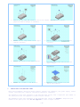
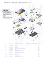
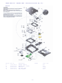
SERVICE MANUAL PLAYSTATION 2
www.kbernet.com
PlayStation®2
SCPH-30000
SCPH-35000
SCPH-30000R
SCPH-39000
SCPH-50000/50000SS
series
series
series
series
series
SERVICE MANUAL
Level-1
PlayStation®2 Level-1 Service & Procedures Manual / Version 4.0
22
NOTE:
Sept 2003
READ THIS DOCUMNENT IN CONJUCTION WITH THE LATEST SERVICE GUIDELINES ISSUED BY SEC
SPECIFICATIONS
General
Power requirements
220-240 V AC, 50/60 Hz
for SCPH-30002D/-30003D/-300004D
-35002/-350003/-350004
Power consumption
50W
for SCPH-30002D/-30003D/-300004D
-35002/-350003/-350004
Dimensions
301 x 78 x 182 mm (w/h/d)
Mass
2.4 kg
Inputs/Outputs on the front
Controller ports (2)
Memory Card slots (2)
USB ports (2)
S400 (I-Link) port (1)
Inputs/Outputs on the rear
HDD by slot (1)
Outputs on the rear
AV Multi out port (1)
RGB, Ycbcr, Y/C, Composite-video,
Audio-L/R, XGA
Digital out port (1)
Optical audio
Supplied accessories
AC power cord (1)
Euro-AV connector (1)
for SCPH-30003/4 & 35003/4
SCPH-30003/4 R & SCPH-39003/4
SCPH-50003/4 & SCPH-50003/4SS
A/V connecting cable (1)
Dualshock2 Analog controller (1)
DISC (GT3)
for SCPH-35002/-350003/-350004
- 1 -
TABLE OF CONTENTS
SCPH-30000 series and SCPH-35000 series GH013 (31/41) MOUNT on board
SAFETY-RELATED COMPONENT WARNING
3
GENERAL INFORMATION
4
1. SERVICE NOTE/CONDITIONS
Conditions
Fault Information & FAQ
Inner Carton Reorder
4
4
4
4
2. WARRANTY
Service Warranty
Reimbursement
4
4
4
3. APPLICABLE MODELS
4
4. LEVEL -1 SERVICE SPECIFICATION
4
5. SPARE PARTS REORDERS
4
6. WARRANTY SEAL CONTROL
5
7. REPORTING (WARRANTY DATA ENTRY)
5
8. REMOVAL OF STUCK DISC
5-6
9. REPAIR PARTS LIST
Exploded Views
SCPH-30002/30003/30004
Overall and Main Block
MD Block
Switch Block
7
7-24
7
7
8
9
(C, C’)
SCPH-30002/30003/30004
(D, D’)
Overall and Main Block
MD Block
GB-003/GB-004 and Place Assy Block
Fan and Rear Panel
Switch Block
10
10
11
12
12
13
SCPH-30002R/30003R/30004R
(F)
Overall and Main Block
MD Block
Switch Assy Block
Power Switch, Fan and Rear Panel
14
14
15
16
17
SCPH-39002/39003/39004/39008
(G)
Overall and Main Block
MD Block
Switch Assy Block
Power Switch, Fan and Rear Panel
18
18
19
20
21
SCPH-50002/3/4/8 & 50002/3/4S S (H)
Overall and Main Block
MD Block
Boards Section
22
23
24
PS2 Peripherals
25
10. QUALITY CONTROL TEST
26
- 2 -
SAFETY-RELATED COMPONENT WARNING
Components identified by mark
and in the parts list are critical to safe operation.
these components with Sony parts whose part numbers appear as shown in this manual.
SAFETY-RELATED COMPONENT WARNING!!.
COMPONENTS IDENTIFIED BY MARK OR DOTTED LINE WITH
MARK ON THE SCHEMATIC DIAGRAMS
AND IN THE PARTS LIST ARE CRITICAL TO SAFE
OPERATION. REPLACE THESE COMPONENTS WITH SONY
PARTS WHOSE PART NUMBERS APPEAR AS SHOWN IN THIS
MANUAL OR IN SUPPLEMENTS PUBLISHED BY SONY.
Replace
CAUTION_
Danger of explosion if battery is incorrectly
replaced. Replace only with the same or
equivalent type recommended by the manufacturer.
Discard used batteries according to the
manufacturer’s instructions.
IMPORTANT_
SONY COMPUTER ENTERTAINMENT DEMANDS THAT AT NO
TIME SHOULD A MOTHERBOARD BE EXCHANGED FROM ONE
CONSOLE TO ANOTHER. NO MCB PARTS ARE INCLUDED ON
LEVEL-1 REPAIR.
SAFETY CHECK-OUT .
After correcting the original service problem,
perform the following safety checks before
releasing the set to the customer:
1. Check the area of your repair for unsoldered
or cold-soldered connections. Check the entire
board surface for solder splashes and bridges.
2. Check the inter board wiring to ensure that no
wires are “pinched” or contact high-wattage
resistors.
3. Look for unauthorized replacement parts,
particularly transistors, that were installed
during a previous repair. Point them out to the
customer and recommend their replacement.
4. Look for parts, which, though functioning,
show obvious signs of deterioration. Point them
out of the customer and recommend their
replacement.
5. Check the line cord for cracks and abrasion.
Recommend the replacement of any such line cord
to the customer.
6. Check the b+ voltage to see it is at the
values specified.
7. Check the antenna terminals, metal trim,
“metalized” knobs, screws, and all other exposed
metal parts for ac leakage.
IMPORTANT_
Do NOT touch any PlayStation®2 parts not listed
on this manual.
CAUTION_
Replace the battery with a Sony CR2032 battery.
Use of any other type of battery may present the
risk of fire or explosion. The battery may
explode if mistreated. Do not recharge,
disassemble, or dispose of in fire.
CAUTION_
The use of optical instruments with this product
will increase eye Hazard. As the laser beam used
in this CD/DVD player is harmful to eyes, do not
attempt to disassemble the cabinet. Refer
servicing to qualified personnel only.
WARNING!! .
WHEN SERVICING, DO NOT APPROACH THE LASER EXIT
WITH THE EYE TOO CLOSELY. IN CASE IT IS NECESSARY
TO CONFIRM LASER BEAM EMISSION, BE SURE TO
OBSERVE FROM A DISTANCE OF MORE THAN 25cm FROM
THE SURFACE OF THE OBJECTIVE LENS ON THE OPTICAL
PICK-UP BLOCK.
NOTIFICATION for environmental assessment .
This model is CR2032 lithium battery onboard
inside on the GD MOUNT as Timer backup power.
CR2032 life may be about 5 to 8 years so you have
very few need for changing to new one. But if you
have necessary to replaced to new one or
disassemble for scrapping, you have to keep your
country low, regulation, standard, etc. of
environmental assessment and safety.
CAUTION_
Use of controls or adjustments or performance of
procedures other than those specified herein may
result in hazardous radiation exposure.
CAUTION for electric shock .
When power is ON, Don’t touch to Power supply
block, AC-inlet, Power switch and so on, not to
get an electric shock at repair.
CAUTION for burning .
When current is supplied, Some of part surface
temperature like EE, GS, Regulater-IC, power
supply, Optical device and so on. These part
surface is become high temperature condition.
When it repair, don’t touch them at a time during
it surface is high temperature condition to take
prevent against burning. Do repair after it is
cooled down enough.
NOTE: Some of the above safety text is NOT applicable to Level-1 Repairs
- 3 -
GENERAL INFORMATION
NOTICE: Copyright by Sony Computer Entertainment Inc. All rights reserved. No reproduced and transferred
required except permission by Sony Computer Entertainment Inc. No commercial use and rental required.
REVISIONS: This manual compiled by first edition of SCPH-30000 series and SCPH-35000 series design data.
Design and Specification will be subject to changed without notice. The latest versions of service manual,
Technical memo, and Technical information should be used together.
1.
SERVICE NOTE/CONDITIONS
Level-1 service is only allowed by Sony Service Centres (SSC) or dedicated Authorised Service
Centre (ASC) note1. Other type of repair still has to be carried out by SEC-ROE as appropriate
jigs or tools are not available to SSC/ASC note1.
1.1.
Conditions
•
SSC and ASC note1 can only perform PlayStation®2 Level -1 repair as described in this
manual;
It is strictly prohibited to perform any Level-2 and/or Level-3 repairs on
PlayStation®2 units;
Level-2 repairs must only be performed by SEC–ROE (or SSC/ASC authorised by SCEE)
Level-3 repairs must only be performed by SEC-ROE;
Any PlayStation®2 unit submitted to any kind of abuse repair will never be
classified as ‘in warranty’;
Units sent to SEC-ROE for Level-2 and/or Level-3 repair that shows any evidence of
abuse 2 will not be compensated;
SSCs and ASCs note1 must have an appropriate Warranty Seal Control procedure
covering the following areas: inventory control, process, audit trail and
replenishment of stock (please refer to paragraph six in this manual for more
details).
•
•
•
•
•
•
1.2.
Fault Information & FAQ
Sony Computer Entertainment Europe (SCEE) will provide Fault Information and
Frequent Asked Questions through the Technical Service Extranet site
(http://tech.scee.net/tech.nsf). This is a secured site and can only be accessed by
personnel authorised by SCEE (please contact SCEE if you require access to this
system).
1.3.
Inner Carton re-order
In the case of defective units arriving at SSC or ASC note1 without the original inner
carton: SCEE will make ‘brown’ inner cartons available to order by SOSA Central
Warehouse. For more information contact SOSA Central Office. Brown inner cartons
can be used for returning consoles repaired locally and as a transportation box to
SEC-ROE.
2
2.
Abuse:
any units missing original components, having additional components (e.g.
modifying chips) and/or physical liquid damage.
WARRANTY
Service Warranty
The warranty on Level-1 repaired PlayStation®2 should be set to 90 days.
eligible to free of charge re -repair within the 90 days warranty.
Repaired units are
I/W Reimbursement system
In case service is carried out in -warranty, please proceed for compensation according to the
standard Warranty Reimbursement rules, outlined in the SEC -ROE Warranty Rulebook.
3.
APPLICABLE MODELS
This Level-1 Service Manual is applicable to the following PlayStation®2 models:
- SCPH-30002 /SCPH-30003 /SCPH-30004
(C)
- SCPH-30002 /SCPH-30003 /SCPH-30004
(D)
- SCPH-35002 /SCPH-35003 /SCPH-35004
(D)
- SCPH-30002R/SCPH -30003R/SCPH-30004R
(F)
- SCPH-39002 /SCPH-39003 /SCPH-39004/SCPH39008
(G)
- SCPH-50002/3/4/8 & SCPH-50002/3/4 SS
(H)
4.
LEVEL-1 SERVICE SPECIFICATION
Definition
Level-1 service is only allowed by SSC or dedicated ASC note1 and specified as follows:
•
Cosmetic and easy repairs using level-1 spare parts mentioned in this manual;
•
Replacement of dedicated parts, such as power supply module, terminal board, etc.
(please refer to this manual for a full list of dedicated parts);
•
Adjustment of mechanical parts (NOT on optical block);
•
Removal of stuck disk;
•
No Problem Found (NPF).
- 4 -
5.
Note 1
6.
SPARE PARTS REORDERS
SSC and ASC note1 are only authorised to order spare parts listed in this manual. Spare parts
should be ordered through existing WRPCE system/procedures. For more information on parts
reorders, please refer to SEC -ROE guidelines/procedures.
Where
no SSC
present in the country
WARRANTY
SEALisCONTROL
Repairs must be controlled by the use of Warranty Seals (Part Number: 3-066-498-01, Tape/Void).
Warranty Seals must be strictly controlled. All countries wishing to perform Level-1 repair on
PlayStation®2, as described in this manual, must submit appropriate Warranty Seal Control
procedures covering the following areas: inventory control, process, audit trail and
replenishment of stock.
To ensure that Warranty Seals are controlled properly, each SSC and ASC note1 must have a
nominated member of staff who is responsible for these parts. They should carry out the
following functions:
•
•
•
•
Confirm that the service centre inventory accurately represents the true stock level when
reported to SCEE;
To report promptly any loss due to damage, theft, defective application or unforeseen
incident;
This person will also be responsible for the periodic reporting to SCEE, and should
maintain the local audit files to be examined by SCEE as part of a stock inventory audit.
SSC and ACS note1 must re-seal all PlayStation®2 units that could not be repaired locally
(Level-1 repair) before shipping the unit to SEC-ROE for Level-2/Level -3 repair.
Reimbursement will not be granted for PlayStation®2 units arriving at SEC-ROE without
warranty seal (even if in-warranty).
7.
REPORTING
SCEE must obtain Level-1 repair information from all countries performing Level-1 repairs
locally. Monthly reports will be extracted from ESQI-line, however it is imperative that
PlayStation®2 is reported on a “model type” basis (e.g. C-model, D-model, etc). Information
must be entered in the ESQI-line in the following format:
Example:
•
Console SCPH-30004 type D = SCPH-30004D
•
Console SCPH-30004R type D = SCPH-30004RD
How to identify model type: All Engineers should be able
to identify consoles by Model type (e.g. "C","D","F","G"),
if not, model type can be identified on the number plate
on the “right bottom left hand corner” next to a number
with the following format: "3 -070-933-01 D" (this last
digit refers to the model typ e)
8.
REMOVAL OF STUCK DISC
IMPORTANT NOTE: PlayStation®2 unit must always be handled in ESD -safe
conditions:
Workbench with anti-ESD mat, connected to earth
Technician should wear wrist/ankle strap, connected to any-ESD-mat
In the case, both, power and loading mechanism are active:
Connect the PlayStation®2 unit to the power and switch the unit on at the back. When the red LED
at the front side is blinking, push this button and the unit will switch one. Disc can be removed
by pushing the eject button.
In case power or loading mechanism is not active:
2. Remove HDD Bay lid at the backside of
the unit.
1. Remove tape void at backside of the
unit.
Note 1
- 5 Where no SSC is present in the country
3. Remove all the caps and screws of the bottom cabinet very carefully (avoid
physical/cosmetic damage on cabinets)
9.
4. Remove the two long screws on the upper
cabinet carefully
5. Remove the caps of the upper cabinet
carefully
6. Remove the screws of the upper cabinet
7. Disconnect the power switch from the
upper cabinet
8. Remove the 4 screws of the MD -block
9. Lift the pulley bracket assy and
remove the software
REPAIR PARTS LIST/EXPLODED VIEWS
Main parts/assembles, which are used by Level-1 centres: All cosmetics, fan, power supply, ribbon
cables, controller port connector and various mechanical components.
The mechanical parts with reference on the exploded view (below) with a respective part number on
the spare parts list are supplied to level-1 repair centres.
The mechanical parts with reference on the exploded view (below) but without a respective part
number on the spare parts list are not supplied to level-1 repair centres.
- 6 -
REPAIR PARTS LIST – EXPLODED VIEWS – SCPH-30002/30003/30004
(C, C’)
Overall and Main Block
Ref-No.
60
61
Part No.
1-468-565-21
1-528-174-41
62
63
64
65
69
70
75
76
88
93
94
95
105
106
112
138
139
142
1-694-767-11
1-763-480-11
1-771-995-12
1-792-491-21
3-066-489-01
3-059-622-02
3-059-626-03
3-059-627-01
3-325-679-21
X-3951-398-1
X-3951-498-1
X-3951-099-1
1-680-147-11
X-3951-317-1
3-066-498-01
1-757-588-11
1-757-590-11
1-757-589-11
Description
Remark
POWER BLOCK
PS2 BATTERY, LITHIUM
OTHER NON -PS2 “LITHIUM CR2032
(CR2032 TYPE)
TYPE BATTERY” MAY BE USED.
TERMINAL BOARD (FRONT)
DC. FAN
SWITCH, POWER (WITH AC INLET)
CABLE, FLEXIBLE FLAT (FFC-290)
SHIELD (B)
SCREW (M3X54), HEAD TAPPING
COVER, SCREW
CAP
SCREW, TAPPING +BV 3X12
COVER ASSY, LOWER
COVER ASSY, UPPER
PLATE ASSY, ORNAMENTAL
PWB, FP-324 FLEXIBLE
LID ASSY
TAPE, VOID
CABLE, FLAT (FFC-308)
CABLE, FLAT (FFC-310)
CABLE, FLAT (FFC-309)
- 7 -
Place code
#00
#25GD
#17
#74
#00
#12
#16
#87
#22
#22
#87
#87
#87
#87
#12
#87
#87
#12
#12
#25GD
REPAIR PARTS LIST – EXPLODED VIEWS – SCPH-30002/30003/30004
(C, C’)
MD Block
Ref-No. Part No.
Description
17
27
28
29
31
TAPPING (B2X6.5)
BRACKET ASSY, PULLEY
TRAY ASSY
BOX ASSY, GEAR
PWB, FLEXIBLE
3-060-400-01
X-3951-154-2
X-3951-153-2
X-3951-156-3
1-680-370-11
Remark
Place code
#10
#10
#10TR
#10GB
#10
- 8 -
REPAIR PARTS LIST – EXPLODED VIEWS – SCPH-30002/30003/30004
(C, C’)
Switch Block
Ref-No. Part No.
Description
50
51
52
53
BUTTON, SWITCH
BRACKET, SWITCH
TPG +P 2X8, TYPE 2, NON-SLIT
SW-355 MOUNT
3-059-665-03
3-059-666-05
7-685-105-11
A-6712-830-A
Remark
- 9 -
Place code
#25SW
#25SW
#25SW
#25SW
REPAIR PARTS LIST – EXPLODED VIEWS – SCPH-30000 series and SCPH-35000 series
(D, D’)
Overall and Main Block for SCPH-30002D/30003D/30004D/35002/35003/35004
Ref-No.
60
62
62
62
75
76
84
93
106
112
151
151
152
152
153
158
162
BV312
M354
M360
Part No.
1-468-605-11
1-694-676-21
1-694-729-21
1-694-769-31
3-059-626-03
3-059-627-01
3-067-170-01
X-3951-722-1
X-3951-317-1
3-066-498-01
1-757-934-11
1-757-934-21
1-823-341-11
1-823-341-21
1-961-160-21
3-068-675-02
3-069-212-01
3-325-679-21
3-059-622-02
3-069-168-01
Description
Remark
POWER BLOCK
TERMINAL BOARD (FRONT)
TERMINAL BOARD (FRONT)
TERMINAL BOARD (FRONT)
COVER, SCREW
CAP
TAPE (20X20), HARNESS STOPPER
COVER ASSY, LOWER
LID ASSY
TAPE, VOID
CABLE, FLEXIBLE FLAT (FFC-011)
CABLE, FLEXIBLE FLAT (FFC-011)
CABLE, FLEXIBLE FLAT (FFC-015)
CABLE, FLEXIBLE FLAT (FFC-015)
HARNESS (HS-059)
SHIELD (HDD)
TAPE, HARNESS STOPER
SCREW, TAPPING +BV 3X12
SCREW (M3X54), HEAD TAPPPING
TITE (CZN), M3X6 +BV S
- 10 -
Place code
#00
#17
#17
#17
#22
#22
#87
#87
#87
#87
#12
#12
#12
#12
#12
#87
#16
#87
#87
#87
REPAIR PARTS LIST – EXPLODED VIEWS – SCPH-30000 series and SCPH-35000 series
(D, D’)
MD Block
Ref-No. Part No.
Description
17
27
28
31
TAPPING (B2X6.5)
BRACKET ASSY, PULLEY
TRAY ASSY
PWB, FLEXIBLE
3-060-400-01
X-3951-609-1
X-3951-608-1
1-680-370-12
Remark
Place code
#10
#10
#10TR
#10
- 11 -
REPAIR PARTS LIST – EXPLODED VIEWS – SCPH-30000 series and SCPH-35000 series
(D, D’)
GB-003/GB-004 and Plate Assy Block
Ref-No.
61
153
GB003
GB004
GB005
GB006
Part No.
1-528-174-41
1-961-160-21
A-6712-923-A
A-6712-984-A
A-6712-996-A
A-6712-984-A
Description Remark
BATTERY, LITHIUM (CR2032 TYPE)
HARNESS (HS-059)
GB-003 MOUNTUse for combine with
GB-004 MOUNTUse for combine with
GB-005 MOUNTUse for combine with
GB-006 MOUNTUse for combine with
GH010.
GH012.
GH013.
GH014.
Fan and Rear Panel Block
Ref-No.
Part No.
Description
Remark
63
63
63
64
64
159
BV312
1-763-480-23
1-763-544-22
1-763-756-11
1-771-995-31
1-786-209-21
3-068-676-12
3-325-679-21
DC. FAN
FAN, DC
FAN, DC
SWITCH, POWER (WITH AC INLET)
SWITCH, POWER (AC INLET)
PANEL, REAR
SCREW, TAPPING +BV 3X12
- 12 -
Place code
#74
#74
#74
#00
#00
#87
#87
Place code
#25GB
#12
#25GB
#25GB
#25GB
#25GB
REPAIR PARTS LIST – EXPLODED VIEWS – SCPH-30000 series and SCPH-35000 series
(D, D’)
(92) Switch Assy Block
Ref-No.
code
92
92
92
50
51
51
52
Part No.
A-6705-338-A
A-6705-424-A
A-6705-401-A
3-059-665-03
3-059-666-05
3-066-494-01
7-685-105-11
Description
Remark
SWITECH BLOCK ASSY
Used for combine with GH010.
SWITECH BLOCK ASSY
Used for combine with GH013.
SWITECH BLOCK ASSY
Used for combine with GH012/GH014.
BUTTON, SWITCH
BRACKET, SWITCH
BRACKET, SWITCH
TPG +P 2X8, TYPE 2, NON-SLIT
- 13 -
Place
#25SW
#25SW
#25SW
#25SW
#25SW
#25SW
#25SW
Overall and Main Block for SCPH-30002 R(AU3) /-30003 R(CEK) /-30004 R(CEL)
(F)
Ref-No.
Part No.
Description
Remark
60
60
61
62
62
62
75
76
84
93
95
106
112
151
151
151
152
152
157
158
162
BV312
BV316
M354
M360
1-468-605-11
1-468-605-21
1-528-174-41
1-694-873-11
1-694-874-11
1-694-875-11
3-059-626-03
3-059-627-01
3-067-170-01
X-3951-722-2
X-3951-099-1
3-070-847-11
3-066-498-01
1-757-934-11
1-757-934-21
1-757-934-31
1-823-341-11
1-823-341-21
3-071-971-01
3-071-973-01
3-069-212-01
3-325-679-21
3-325-679-91
3-059-622-02
3-069-168-01
POWER BLOCK
for 220-240V AC
POWER BLOCK
for 220-240V AC
BATTERY, LITHIUM (CR2032 TYPE)
TERMINAL BOARD (FRONT)
TERMINAL BOARD (FRONT)
TERMINAL BOARD (FRONT)
COVER, SCREW
CAP
TAPE (20X20), HARNESS STOPPER
COVER ASSY, LOWER
PLATE ASSY, ORNAMENTAL
LID
TAPE, VOID
CABLE, FLEXIBLE FLAT (FFC-011)
CABLE, FLEXIBLE FLAT (FFC-011)
CABLE, FLEXIBLE FLAT (FFC-011)
CABLE, FLEXIBLE FLAT (FFC-015)
CABLE, FLEXIBLE FLAT (FFC-015)
SHEET, INSULATING
SHIELD HDD (F)
TAPE, HARNESS STOPPER
SCREW, TAPPING +BV 3X12
TAPPING +BV 3X16
SCREW (M3X54), HEAD TAPPING
TITE (CZN), M3X6 +BV S
- 14 -
Place
#00
#00
#25GH
#17
#17
#17
#22
#22
#87
#87
#87
#87
#87
#12
#12
#12
#12
#12
#16
#87
#87
#87
#87
#87
#87
MD Block for SCPH-30002 R(AU3) /-30003 R(CEK) /-30004 R(CEL)
(F)
Ref-No.
Part No.
Description
Remark
17
27
28
31
3-060-400-01
X-3952-059-1
X-3952-060-1
1-680-370-21
TAPPING (B2X6.5)
BRACKET ASSY, PULLEY
TRAY ASSY
PWB, FLEXIBLE
- 15 -
Place
#10
#10
#10TR
#10
Switch Assy Block for SCPH-30002 R(AU3) /-30003 R(CEK) /-30004 R(CEL)
Ref-No.
50
51
51
52
53
53
Part No.
3-059-665-03
3-059-666-05
3-066-494-01
7-685-105-11
A-6715-500-A
A-6714-500-A
A-6787-465-A
A-6787-466-A
Description
(F)
Remark
BUTTON, SWITCH
BRACKET, SWITCH
BRACKET, SWITCH
TPG +P 2X8, TYPE 2, NON-SLIT
sw-367 COMPL
SW-367 MOUNT
sw-367 COMPL (VA)
SW-367 MOUNT (VA)
- 16 -
Place
#25SW
#25SW
#25SW
#25SW
#25SW
#25SW
Power Switch, Fan and Rear Panel Assy Block for SCPH-30002 R(AU3) /-30003 R(CEK) /-30004 R(CEL)
Ref-No.
Part No.
Description
Remark
(F)
Place
63
63
63
1-763-480-31
1-763-554-31
1-763-756-21
DC.FAN
FAN DC.
FAN DC.
64
64
1-771-994-31
1-786-209-21
SWITCH, POWER (WITH AC INLET) for SCPH-30001 R
#00
SWITCH, POWER (WITH AC INLET) for SCPH-30002 R /-30003 R /-30004 R
SWITCH, POWER (WITH AC INLET) for SCPH-30005 R /-30006 R /-30007 R
159
159
3-071-901-01
3-071-901-11
PANEL, REAR
PANEL, REAR
BV312 3-325-679-21 SCREW,
#74
#74
#74
TAPPING +BV 3X12
- 17 -
for SCPH-30001 R/-30005 R
#87
for SCPH-30002 R/-30003 R/-30004 R
SCPH-30006 R/-30007 R
#87
#87
Overall and Main Block for SCPH-39002 / 39003 / 39004 / 39008
(G)
Ref-No.
Part No.
Description
Remark
60
61
62
75
76
84
92
93
95
106
112
112
151
152
157
158
162
B265
BV312
BV316
M354
M360
T250
1-468-605-31
1-528-174-41
1-694-875-11
3-059-626-03
3-059-627-01
3-067-170-01
A-6787-644-A
X-3951-722-2
X-3951-099-1
3-070-847-01
3-066-498-01
3-079-117-01
1-757-934-11
1-823-341-11
3-071-971-01
3-071-973-01
3-069-212-01
3-069-170-01
3-325-679-21
3-070-296-01
3-059-622-02
3-069-168-01
3-071-976-01
POWER BLOCK for 220-240V AC
BATTERY, LITHIUM (CR2032 TYPE)
TERMINAL BOARD (FRONT)
COVER, SCREW
CAP
TAPE (20X20), HARNESS STOPPER
SWITCH BLOCK ASSY
COVER ASSY, LOWER
PLATE ASSY, ORNAMENTAL
LID
TAPE, VOID
TAPE, VOID (For SCPH-39008)
CABLE, FLEXIBLE FLAT (FFC-011)
CABLE, FLEXIBLE FLAT (FFC-015)
SHEET, INSULATING
SHIELD HDD (F)
TAPE, HARNESS STOPPER
TAPPING (B2X6.5)
SCREW, TAPPING +BV 3X12
TAPPING +BV 3X16
SCREW (M3X54), HEAD TAPPING
TITE (CZN) M3X6 +BV S
TAPPING (2X5)
- 18 -
Place code
#00
#25GH
#17
#22
#22
#87
#87
#87
#87
#87
#87
#87
#12
#12
#16
#87
#87
#87
#87
#87
#87
#87
#87
MD Block for SCPH-39002 / 39003 / 39004 / 39008
(G)
Ref-No.
Part No.
Description
17
27
28
31
3-060-400-01
X-3952-059-1
X-3952-060-1
1-680-370-22
TAPPING (B2X6.5)
BRACKET ASSY, PULLEY
TRAY ASSY
PWB, FLEXIBLE
- 19 -
Remark
Place code
#10
#10
#10TR
#10
Switch Assy Block for SCPH-39002 / 39003 / 39004 / 39008
(G)
Ref-No.
Part No.
Description
50
51
51
52
3-059-665-03
3-059-666-05
3-066-494-01
7-685-105-11
BUTTON, SWITCH
BRACKET, SWITCH
BRACKET, SWITCH
TPG +P 2X8, TYPE 2, NON-SLIT
53
A-6787-551-A
A-6787-552-A
COMPLETE PWB (VA), SW-373
SW-373 MOUNT
Use with GH018 MOUNT
#25SW
53
A-6787-553-A
A-6787-554-A
COMPLETE PWB (VA), SW-373(VA) Use with GH018 MOUNT
SW-373 MOUNT (VA)
#25SW
53
A-6787-645-A
A-6787-646-A
COMPLETE PWB (VA), SW-382
SW-382 MOUNT
Use with GH019 MOUNT
#25SW
53
A-6787-647-A
A-6787-648-A
COMPLETE PWB (VA), SW-382(VA) Use with GH019 MOUNT
SW-382 MOUNT (VA)
#25SW
53
A-6787-976-A
A-6787-977-A
COMPLETE PWB, SW-393
SW-393 MOUNT
Use with GH022 MOUNT
#25SW
53
A-6787-978-A
A-6787-979-A
COMPLETE PWB (VA), SW-393
SW-393 MOUNT (VA)
Use with GH022 MOUNT
#25SW
- 20 -
Remark
Place code
#25SW
#25SW
#25SW
#25SW
Power Switch, Fan and Rear Panel Assy Block for SCPH-39002 / 39003 / 39004 / 39008
(G)
Ref-No.
Part No.
Description
63
64
159
BV312
1-763-480-31
1-786-209-21
3-071-901-01
3-325-679-21
DC. FAN
SWITCH, POWER (WITH AC INLET)
PANEL, REAR
SCREW, TAPPING +BV 3X12
- 21 -
Remark
Place code
#74
#00
#87
#87
Overall and Main Block for SCPH-50002 / 50003 / 50004 / 50008 ( H & H SS )
Ref-No.
Part No.
Description
1
2
3
4
5
6
7
8
13
15
169487513
307455511
308452101
307454801
307455501
307454901
307455601
308450601
307455001
306625301
TERMINAL BOARD (FRONT)
SCREW, +BV TAPPING
SCREW (M3X27), TAPPING
COVER, SCREW
SCREW, +BV TAPPING
CAP
SCREW, BRAZIER HEAD P TIGHT
PANEL (H), REAR
LID
TAPE, VOID
- 22 -
MD Block for SCPH-50002 / 50003 / 50004 / 50008 ( H & H SS )
Ref-No.
Part No.
Description
108
128
308452201
X39535891
TRAY (H)
BRACKET (H) ASSY, PULLEY
- 23 -
Boards Section for SCPH-50002 / 50003 / 50004 / 50008
( H & H SS )
Ref-No.
Part No.
Description
54
55
56
57
58
61
62
63
65
66
66
68
69
70
307455301
146875821
308451901
175793411
308452001
168037023
308029301
X39535881
308450901
X39535871
X39537411
182715011
308580001
308029401
TITE (CZN), M3X6 +BV S
POWER BLOCK (SWITCHING REGULATOR)
SHEET (H),INSULATING
CABLE, FLAT (FFC-011)
SCREW (B2X6.5B), TAPPING
FLEXIBLE BOARD
SHEET (A), ELECTRIC HEAT
SHIELD (A) (H) ASSY
BUTTON (H), SWITCH
PLATE (H) ASSY, ORNAMENTAL
PLATE (H) ASSY, ORNAMENTAL SILVER (H SS)
CABLE, FLEXIBLE FLAT (FFC-019)
SHEET(H), FERRITE
SHEET (DRIVER), ELECTRIC HEAT
- 24 -
PS2 Peripherals
Ref-No.
Part No.
Description
AC EURO
157513182
CORD, POWER
CONV
157329111
CONNECTOR, CONVERSION
AV
179202831
AV CABLE
CONT
CONT
182355212
182770211
ANALOG CONTROLLER(DUAL SHOCK 2)
ANALOG CONTROLLER(DUAL SHOCK 2) SILVER
- 25 -
10.
QUALITY ASSURANCE TEST (QA TEST)
Ref-No.
Part No.
Description
n/a
n/a
J-250-407-3A
J-250-407-0A
SVD 4514
SCD 4515
n/a
J-2504-118-A
SVD-E94075
Remark Place
code
n/a
n/a
for SCPH 39002/3/4
n/a
QA-Test-disc is supplied as a spare part. If the units pass test with PS-game, PS2-game
EVERY unit needs a QA-test and has to pass the QA -test. After the QA-test, an aging-test
PlayStationR2 -demo disc needs to be done during two hours. If the unit passes this test,
can be considered as repaired and can be returned to the customer. The following QA-Test
should be followed:
and DVD,
with a
the unit
guidelines
To perform the QA-test, the following equipment is required:
§
•
•
•
•
•
•
Test-CD: SCD 4515 and SVD 4514 and SVD-E94075 (available as spare part)
2 grey (PS) + 2 black (PS2) memory cards (not supplied)1
TV (not supplied) 2
Amplifier with OP dig out connection + loudspeaker (not supplied) 2
USB-cable (not supplied) 2
Optical Digital Cord (not supplied)2
2 Dual Shocks PS2 (not supplied)1
Note:
1
Please use existing stock
2
These equipments are generic equipment and should already be available at SSC and ACS.
Process-description:
1.
2.
3.
4.
5.
6.
7.
8.
9.
10.
11.
12.
13.
14.
15.
16.
Connect Power Cord, AV-cable & optical digital cord to the unit (Backside);
Connect USB-cable and insert the 2 grey memory cards and Dual Shocks (Front side);
Switch the Power ON & push the reset button;
Insert SCD 4515 test disc;
Check Audio and Video: CARD 0 and CARD 1 must be: OK;
Push R1 button on Dual Shock and check Audio and Video;
Push L1 button on Dual Shock and check Audio and Video;
Remove SCD 4515, insert SVD 4515 and push the reset-button;
Replace grey memory cards with the black ones;
Check Screen “ PS2 check disc V2.00” All items must be OK;
Push L1, R1 and red O-button together and “ Check V-RAM” OK, push red O-button again and V RAM: OK;
Push red O-button and check Audio (TV + Loudspeaker) and Video;
Push red O-button and check Audio and Video;
Push red O-button “RD-RAM-test 0.02” OK;
Push red O-button “HDD-connector-test” OK;
Remove disc and switch off the unit.
Date
Written by
Approved by
Warllen Duque
Compliance Manager
Sony Computer Entertainment Europe
Mike Nabarro
Vice-President of Technical Services
Sony Computer Entertainment Europe
09-Nov-2001
*** end of page ***
- 26 -