1
INTERSTATER
Assembly Instruction
Manual
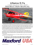
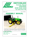
New Holland (Cab or Rops Tractor) Models
TL-80, TL-80A, TL-90, TL-90A. TL-100 & TL-100A
INTERSTATER
Tractors equipped with additional options, special equipment, tractor manufacturer modifications, new tractor models, or Customer alterations may prevent this Mount Kit from
being properly mounted to the tractor. Alamo Group is not responsible for modifications to
the MountKit to accommodate these differences.
Manual
P/N 02981341
ALAMO INDUSTRIAL
1502 E. Walnut
Seguin, Texas 78155
210-379-1480
© 2004 Alamo Group Inc.
INTRODUCTION
ABOUT THIS MANUAL:
The intent of this publication to provide the competent technician with the information necessary
to perform the CORRECT Assembly to the Alamo Industrial Product. This will, in turn provide for
complete customer satisfaction
It is hoped that the information contained in this and other Manuals will provide enough detail to
eliminate the need for contact of the Alamo Industrial Technical Service Dept. However, it should be
understood that many instances may arrive where correspondence with the Manufacturer is necessary.
CONTACTING MANUFACTURER: (Please help us Help You! Before You Call! )
Alamo Industrial Service Staff Members are dedicated to helping you solve your problem, or
your customer’s service problem as quickly and efficiently as possible. Unfortunately, we receive
entirely to many calls with only a minimum amount of information. In some cases, the correspondent
has never gone out to look at the equipment and merely calls inquiring of the problems described to him
by the operator or customer.
Most calls received by Alamo Industrial Service can be classified into approx. 6 general categories.
1.
Hydraulic or Mechanical Trouble Shooting.
2.
Request for Technical Information or Specifications.
3.
Mounting or Fitting Problem.
4.
Special Service Problem.
5.
Equipment Application Problems.
6.
Tractor Problem Inquiries.
HOW YOU CAN HELP:
Make sure the call is necessary! Most of the calls received may not be necessary if the Dealer
Service Technician would do the following.
1.
Check the Service Information at your Dealership provided by Alamo Industrial, This
would include, Service Bulletins, Information Bulletins, Parts Manuals, Operators Manuals, Assembly
Manual or Service Manual, many of these are available via the Alamo Industrial Internet site (www.AlamoIndustrial.Com). Attempt to diagnose or repair problem before calling.
2.
If a call to Alamo Industrial is needed, Certain Information should be available and ready
for the Alamo Industrial Service Staff. Such information as, Machine Model, Serial Number, Your Dealer
Name, Your Account Number and Any other information that will be useful. This information is vital for
the development of a prompt and correct solution to the problem. This will also help to develop a
database of problems and related solutions, which will expedite a solution to future problems of a similar
nature.
3.
The technician may be asked to provide detailed information about the problem
including the results of any required trouble shooting techniques. If the information is not available, The
technician may be asked to get the information and call back. Most recommendations for repairs will
be based on the procedures listed in the Service Manual / Trouble Shooting Guide and Information
provided by customer.
CONTACT ALAMO INDUSTRIAL:
Alamo Industrial, 1502 E. Walnut St. Seguin TX. 78155, Technical Service Dept. PH: 830-379-1480
Interstater (NH TL-80, 90 & 100 Asy. Man.) 06/04
© 2004 Alamo Group Inc.
Page
0-1
INDEX - INTERSTATER
ITEM
PAGE NO.
INDEX INTERSTATER
Introduction (Index Section) .................................................................... 0-1
General Information (Index Section)........................................................ 0-4 to 0-5
Index........................................................................................................ 0-2 to 0-3
SECTION 1
Pre-Delivery Inspection Checklist............................................................1-1 to 1-4
SECTION 2
Driveshaft & Pump Installation................................................................ 2-1 to 2-11
Driveshaft & Pump Schematic............................................................... 2-2
Pulley Adapter......................................................................................... 2-3
Modify Tractor Bolster............................................................................. 2-3
Modify Battery Tray.................................................................................. 2-3 to 2-5
Install Pump Driveshaft............................................................................2-3 to 2-5
Install Front Pump Mount Asy.................................................................. 2-5 to 2-6
Install Pump (Motor Supply Pump).......................................................... 2-6
Install Pump (Cylinder Supply Pump)..................................................... 2-6 to 2-8
Tank Mounting Brackets.......................................................................... 2-8
Tank Installation...................................................................................... 2-9 to 2-11
Pump to Tank Hoses.............................................................................. 2-9 to 2-11
Oil Return Pressure Gauge..................................................................... 2-11
Oil Temperature Gauge........................................................................... 2-11
SECTION 3
Fuel Tank Modification............................................................................. 3-1 to 3-2
SECTION 4
Mainframe Installation.............................................................................. 4-1 to 4-7
Remove Tractor Steps............................................................................ 4-2
Remove tractor Draw Bar and Mount..................................................... 4-2
Mainframe Front Support Brackets......................................................... 4-2 to 4-5
Install Mainframe Under Tractor.............................................................. 4-3 to 4-5
Wing Lift Frame....................................................................................... 4-6
Wing Lift & Tilt Cylinders......................................................................... 4-7
SECTION 5
Wing Mower Installation.......................................................................... 5-1 to 5-11
Wing Magnetic Cut Off Switches and Mounts.........................................5-2 to 5-5
Wing Mower Pivot Brackets.................................................................... 5-3 to 5-5
Cut Off Magnetic Pick-up Switch Wiring................................................. 5-4 to 5-7
Wing Lift Cylinders.................................................................................. 5-4 to 5-5
Motor Cut Off Solenoid............................................................................ 5-5
Wing Hose Connections......................................................................... 5-6 to 5-11
Pump Shield Installation.......................................................................... 5-6
Electrical Schematic............................................................................... 5-7
Motor Hose Schematic............................................................................ 5-8 to 5-11
Continued Next Page
Interstater (NH TL-80, 90 & 100 Asy. Man.) 06/04
© 2004 Alamo Group Inc.
Page
0-2
INDEX - INTERSTATER
ITEM
PAGE NO.
SECTION 6
Joystick, Valve & Control Cables.............................................................6-1 to 6-14
Prepare Control Valve (Cylinder Control)................................................ 6-2
Install Control Valve (Cylinder Control).................................................... 6-2
Connect Control Valve Hoses................................................................. 6-2 to 6-5
Connect Control Cables to Valve............................................................ 6-4 to 6-5
Joystick Mounting Bracket Installation.................................................... 6-6 to 6-7
Control Cables & Wire Harness Through Tractor Floor......................... 6-7
Cable Control Handles............................................................................ 6-7 to 6-12
Push Pull Cut Off Switches.................................................................... 6-10 to 6-12
Control Valve Hose Schematic............................................................... 6-11
Control valve for Rops Model.................................................................. 6-12
Wire Harness Schematic....................................................................... 6-13 to 6-14
SECTION 7
Rear Mower Installation........................................................................... 7-1 to 7-8
Install Rear Lift Chains to Tractor............................................................ 7-2
Upper And Lower Hitch Pins....................................................................7-2 to 7-3
Driveline Connection................................................................................7-3
Leveling Rear Mower................................................................................
7-4
Driveline Slip Clutch Preparation............................................................. 7-5
Shields and Guards................................................................................. 7-5
Lubrication Chart..................................................................................... 7-6
Initial Start Up Procedure......................................................................... 7-7 to 7-8
Oil Tank Filling......................................................................................... 7-7 to 7-8
SECTION 8
Mounting Specifications........................................................................... 8-1 to 8-4
Interstater (NH TL-80, 90 & 100 Asy. Man.) 06/04
© 2004 Alamo Group Inc.
Page
0-3
GENERAL INFORMATION
The tools you will need at the assembly site are as follows:
1.
2.
3.
4.
5.
6.
7.
8.
9.
Impact wrench or socket and ratchet set.
Rubber mallet.
Box-end, Allen, and adjustable wrenches.
Alignment pins.
Forklift or hydraulic floor jacks with rolling back boards.
Small chain hoist or block-and-tackle.
Multidirectional Levels.
Hydraulic Filter Buggy or Cart.
Safety shoes, safety glasses, and gloves.
A hard hat should be worn by anyone working under any raised component.
Remember to follow each step closely and cautiously. Be aware of all support personnel at all times.
Keep the assembly area as clean as possible; clean up all spills when they occur. An uncluttered
assembly area and a crew that is sensitive to the hazards involved in putting this implement together
will help prevent accidents. Keep all unauthorized personnel from the area. Do not allow children near
the assembly site nor allow them on or near the tractor after assembly. There is no safe place for
anyone except the operator on the tractor and those assisting with the assembly.
RECOMMENDED TORQUE VALUES CHART:
RECOMMENDED TORQUE IN FT.-LBS. (Nm)
COARSE AND FINE THREADS
5 (D)
2 (B)
8 (F)
Bolt
Dia.
Plain
Head
Three
Dashes
Six
Dashes
1/4"
5/16"
3/8"
7/16"
1/2"
9/16"
5/8"
3/4"
7/8"
1"
1-1/8"
1-1/4"
Not used
Not used
Not used
35 (47)
55 (75)
75 (102)
105 (142)
185 (251)
160 (217)
250 (339)
330 (447)
480 (651)
10 (14)
20 (27)
35 (47)
55 (75)
85 (115)
130 (176)
170 (230)
300 (407)
445 (603)
670 (908)
910 (1234)
1250 (1695)
14 (19)
30 (41)
50 (68)
80 (108)
120 (163)
175 (237)
240 (325)
425 (576)
685 (929)
1030 (1396)
1460 (1979)
2060 (2793)
Interstater (NH TL-80, 90 & 100 Asy. Man.) 06/04
© 2004 Alamo Group Inc.
Page
0-4
GENERAL INFORMATION
To help you assemble your new Brahma and mount it to your tractor, we provide you with
drawings, instructions, and general information. When needed, you can get information or
clarification from Your Dealer or Alamo Group Customer Service.
This publication provides general information not specifically for your case or tractor, but, in
connection with the drawings and Parts Section, this publication offers you some valuable
assistance - please read it thoroughly.
The mount kits are made for selected tractors with standard configurations. Only the noted
options and tire sizes listed in the model specifications will work with these mount kits. Other
options, front axles, or different tire sizes may prevent the mount kit from fitting your nonstandard
tractor. Alamo Group cannot take responsibility for these problems or any modifications made to
the unit.
Throughout these instructions, In the Parts Mnaual, Operators Manual and decals on unit you will
see the following symbles, pay close attenion to them. References are made to right or left
directions. Right and left are determined by sitting on the tractor seat and facing the direction of
travel.
This is the Safety-Alert symbol. When you see this symbol on your machine
or in these instructions, be alert to the potential for personal injury. Follow
recommended precautions and safe operating practices.
DANGER!
A signal word - DANGER, WARNING, or CAUTION - is used with the Safety Alert
symbol. DANGER identifies the most serious hazards.
WARNING!
Safety signs with signal word
more serious hazards.
CAUTION!
General precautions are listed on CAUTION safety sign. CAUTION also
calls attention to safety messages in these instructions.
Interstater (NH TL-80, 90 & 100 Asy. Man.) 06/04
© 2004 Alamo Group Inc.
Page
WARNING are typically used to point out
0-5
NOTES
Interstater (NH TL-80, 90 & 100 Asy. Man.) 06/04
© 2004 Alamo Group Inc.
Page
0-6
Section 1
INTERSTATER
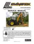
New Holland
TL100 Tractor
PRE-DELIVERY INSPECTION
CHECKLIST
Interstater (NH TL-80, 90 & 100 Asy. Man.) 06/04
© 2004 Alamo Group Inc.
Page
1-1
PRE-DELIVERY INSPECTION CHECKLIST
Pre-Operation Inspection:
Check the following items before operating the unit to
assure that they are properly assembled. (See following page 1-4 for component location)
Saftey Equipment:
___
___
___
___
___
___
___
Operators Manual is with Unit.
The Safety Decals are installed as listed in the Assembly Manual.
Valve operation plate is installed.
Operators cage or Tractor Cab is in place
Deflectors are installed on the Mower Head
Tractor Rops or Cab with seatbels installed properly.
All Foot Guards and safety switch are installed and functional.
Frame:
___
___
___
___
___
___
Axle Plate Bolts are torqued.
Head Mounting Bolts tightened.
Frame attaching Bolts tightened.
Front Support Bolts are torqued.
Hydraulic Tank mounting Pins / Bolts in place correctly.
All Welds inspected toinsure proper welds and locations.
Hydraulic System:
___
___
___
___
___
___
___
Oil Level in Hydraulic Tank is within the sight gauge. (Item 5 page 1-4)
Hose connections are tight.
Hoses do not have any kinks or twist in them.
Front Pump Shaft adapter bolts are tight.
Front Pump Shaft Coupler / Drive Shaft is lubricated and has an anti-seize compound
on the Splines of Pump and Shafts.
The Pump Drive Shaft has correct alignment.
Suction Hose has no leaks or kinks.
Flail Mower Head:
___
___
___
___
___
___
___
___
___
Skid Shoe Bolts are torqued to 120 ft-lbs
Motor Bolts are torqued to 120 ft-lbs
Belt Alignment& tension adjustment is correct.
Cutter shaft bearings are properly lubricated
Roller bearings are properly lubricated
Blades swing freely.
All Pins and Clips for Rear Mower are installed
Clutch on Rear Mower has been checked for proper adjustment and conditions per
parts book reguirments.
All Belt guards are installed correctly.
Interstater (NH TL-80, 90 & 100 Asy. Man.) 06/04
© 2004 Alamo Group Inc.
Page
1-2
PRE-DELIVERY INSPECTION CHECKLIST
Pre-Operation Inspection:
Check the following items before operating the unit to assure
that they are properly assembled. (See following page 1-4 for component location)
Tractor Mower Operation Inspection:
Using all Safety precautions, operate the Tractor and Mower unit for 30 minutes and
while the unit is running check the following items: Note! Only make adjustments after
the mower has been turned off and all motion has stopped and all hydraulic pressure
has been relieved.
___ Check for Hydraulic oil leaks at the hose connections
___ Operate the boom and mower head throughout its full range of motion and check
for hose's rubbing, pinching, or kinking.
___ Make sure the Return Filter Gauge is reading in the Green after Oil is warm.
___ Check the function of the Mower Head On-Off Valve and switch for proper function
___ Make sure that the tractor will not start with the mower on-off switch in the on
position.
___ Check the Blade Rotation for the Rotary Mower Head to make sure it is turning
Clockwise looking from the top of the mower deck.
___ Make sure the control valve boom movements agree with the valve operation decal.
___ Make Sure Boom Movement operates as expected and is smooth and under control
(no air in the control system)
___ Look for any unusual or excessive noise or vibrations.
___ Make sure the left rear wheel of the tractor stays on the ground when the boom is
fully extended horizontally with 200 lbs. placed on the outside of the mower head.
Post-Operation Inspection:
___ Check that the oil in the hydraulic tank has not turned milky in color or has foam on top.
___ Check that there are no loose fasteners or hardware.
Interstater (NH TL-80, 90 & 100 Asy. Man.) 06/04
© 2004 Alamo Group Inc.
Page
1-3
PRE-DELIVERY INSPECTION CHECKLIST
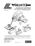
Tractor - Mower Component Location
For Check List
Pumps, Hyd.
Tank & Cover
Right Wing
Flail
Left Wing
Flail
RH SIDE OF
TRACTOR
LH SIDE OF
TRACTOR
Rear Center
Flail
Interstater (NH TL-80, 90 & 100 Asy. Man.) 06/04
© 2004 Alamo Group Inc.
Page
1-4
Section 2
INTERSTATER
Driveshaft & Pump
Installation
New Holland
TL-100 Tractor
Interstater (NH TL-80, 90 & 100 Asy. Man.) 06/04
© 2004 Alamo Group Inc.
Section 2 - 1
Driveshaft & Pump Schematic
Hyd Pump
(Cyl Circuit)
Drive
Belt
Driven
Pulley
Shield
1234
1234
Pulley Adapter
Mounting Bolts
Locknut
Tractor Engine
Pulley
123456
123456
123456
Mounting
Bolt & Washer
* Bearing
Collar
Driveshaft
** Pump
Mount
Plate
Drive Pulley &
Splined Sleeve
Weldment
Pulley
Adapter
* Driveshaft
Bearing
** Small (Cyl Hyd) Pump Mount Plate mounts here
Tandem Pump for Dual Wings
Pump Mount
Weldment
12
12
12
12
Left Wing Pump
12345
12345
12345
12345
Right Wing Pump
Interstater (NH TL-80, 90 & 100 Asy. Man.) 06/04
© 2004 Alamo Group Inc.
Section 2 - 2
* Driveshaft Bearing installs into
pump mount weldment here.
Driveshaft, Pump & Tank Installation
Pulley Adapter & Driveshaft:
1.
Remove Engine Guard Screen. The Engine
on the LH side has a bolt on screen cover that will
need to be removed to gain access to the crank
shaft pulley (See Figure 1).
2.
Install Pulley Adapter to Engine Crankshaft
Pulley. The Spined Pulley adapter bolts to the
engine crankshaft pulley with 4 bolts. These can
difficult to get to when tightening the bolts. Tighten
the bolts that you can get to from LH side, it may
require that you remove the guard from the RH
engine side to gain access to tighten the bolt. (See
Figure 2)
Figure 1
3.
Re-Install Engine Guard Screen. Put the
engine guard back on the LH side of the engine using
the same bolts that were removed (See Figure 1).
4.
Remove The Battery and Battery Tray. Disconnect the battery cables from the battery which is
located in front of the tractor radiator. The Battery
and Battery Tray will have to be removed before the
driveshaft can be installed. The Battery tray and the
Battery Hold Down will be reused. (See Figure 3).
The battery is held down with a piece that is
retained with the front two bolts. The rear
has two bolts also. The RH rear will also
have the battery ground cable connected to
it.
5.
Modify Tractor Front Bolster. The Front
Bolster of the tractor will have to be modified by
grinding part of it off. Before any grinding is done
cover the front of the radiator so the metal from
grinding will not go into the radiator or Air condition
condenser cooling fins, a piece of card board works
well for this. It is recommended that a 1-1/2" wide by
1/4" or better be ground in the center under where
the driveshaft will run. This Space will have to be
check and adjusted accordingly (See Figure 3 &
Figure 4). Clean the metal dust from around front
bolster with a shop vac. DO NOT use air to blow
them out as they will blow into the engine compartment and be blown back out next time engine is
started.
Figure 2
Card Board covering Radiator &
Air Conditioning Condenser
Figure 3
Interstater (NH TL-80, 90 & 100 Asy. Man.) 06/04
© 2004 Alamo Group Inc.
Section 2 - 3
Driveshaft, Pump & Tank Installation
5.
Install Driveshaft. The driveshaft is to be installed under radiator and into the crankshaft pulley
adapter. The drive shaft is splined on both ends. The splines will have to align with the spline in the
crankshaft pulley. The driveshaft will lay on the front bolster in the ground out area for now (See Figure 4).
If you push the driveshaft in until it bottoms out in
the pulley adapter and hold in on it, the driveshaft
should clear the front bolster. If it doesn't then you
will need to grind more out. After the driveshaft
clears and the metal grinding have been
cleaned remove the card board (or what ever)
you covered the radiator with.
6
Install Battery Tray. There are 4 spacers
that are needed to raise the battery tray up from
stock height so it will clear the driveshaft.
Install these spacer onto the tractor bolster (See
Figure 5). You will need to use the four new bolts
which are longer than the ones you removed from
the battery tray. Install the Battery tray down over
the four spacers and install the four new bolts, the
two front bolts will have flatwashers and the RH
rear bolt will have the battery ground cable connected to it. The two front bolts will have be
removed to install battery later. (See Figure 6)
Figure 4
7.
Install Battery. The Battery will need to be
slid into place, for this the two front battery tray
bolts and battery hold down will have to be removed (See Figure 7) . Slide battery in until the
groove on the back bottom side of battery is into
back side of batter tray. Install front two bolts and
the battery hold down (See Figure 8). Make certain
the hold down is set into the groove along the
bottom of the battery before tighten the two front
bolts.
Figure 6
Figure 5
Figure 7
Interstater (NH TL-80, 90 & 100 Asy. Man.) 06/04
© 2004 Alamo Group Inc.
Section 2 - 4
Driveshaft, Pump & Tank Installation
8.
Reconnect Battery Cables. The Battery
cables can be reconnected now to test fit, but it is
best to leave the ground cable disconnected from
the batter until after all the wiring of the wiring
harness is completed later in the assembly process. (See Figure 8).
9.
Install Pump Mount Weldment. The pump
mount weldment has a carrier bearing in it. There
is a locking collar on the bearing, make certain the
set screw in locking collar is loosened before trying
to slide it over the driveshaft. Start the driveshaft
through the carrier bearing (See Figure 9). There
are two spacers that must install between pump
mount weldment and tractor bolster, install these
two spacers now (See Figure 9). Each spacer will
have two holes, The Carrier Bearing should slide
over drive shaft far enough for the pump weldment
to fit tightly up against the spacers and the spacers
against the tractor bolster. Tighten the four mounting bolts to tighten the pump mount weldment (See
Figure 10). Check the clearance between drive
shaft and tractor front bolster where you ground
bolster. It the driveshaft doesn't have clearance
the bolster will have to be ground down again (See
Figure 10). DO NOT Tighten locking collar on
carrier bearing yet.
Figure 8
Spacer
Blocks
10.
Coat the splined end of shaft with antiseize compound. Coat the end of the shaft with a
anti-seize compound (See Figure 11). Do not use
an excessive amount and do not use grease.
Figure 9
Figure 11
Figure 10
Interstater (NH TL-80, 90 & 100 Asy. Man.) 06/04
© 2004 Alamo Group Inc.
Section 2 - 5
Driveshaft, Pump & Tank Installation
11.
Install Splined Coupler /Pulley Weldment.
The Drive belt for the splined Coupler Pulley
weldment must be installed at the same time. Note
the long end of the splined coupler goes on first.
Slide it on until the roll pin that is driven trough the
splined coupler is bottom against the driveshaft
(See Figure 12).
12.
Prepare the Pump for Installation. Coat the
splined shaft of the pump with a anti-seize compound. Install the pump shaft into the splined
coupler until pump is mount with the flange ring into
the pump mount plate (See Figure 13 & 14).
13.
Install Pump Retaining bolts. The pump
retaining bolts are to be installed by hand. The
pump should be seated into the opening provided
in the pump mount weldment for the pump flange
ring (See Figure 15). Install the two pump mounting bolts and tighten them. DO NOT use the bolts
to force pump flange into the pump mount
weldment, if you do you will break the flange ears
off of the pump. If the pump will not go by pushing
it in take the pump out and check the opening for
excess paint or burrs. The pump must be installed
as shown in figure 14 and 15. The side of the pump
with the four fittings will be to the RH side of the
tractor when standing behind tractor looking forward.
Figure 12
Figure 13
Install & Tighten
the two pump
mounting bolts
Figure 14
Figure 15
Interstater (NH TL-80, 90 & 100 Asy. Man.) 06/04
© 2004 Alamo Group Inc.
Section 2 - 6
Driveshaft, Pump & Tank Installation
14.
Adjust Splined Coupler/ Pulley Weldment.
The splined Coupler Pulley weldment must be
adjusted to run in the correct location. Note the
long end of the splined coupler goes on first and
has a roll pin that is driven trough the splined
coupler. Push the pulley outward until the splined
coupler is slid as far as it will go onto the Pump
Shaft (See Figure 16). Pull the driveshaft out of the
crankshaft pulley adapter until it is in the splined
coupler / pulley weldment as far as it will go.
Tighten the setscrew in the carrier bearing locking
collar, this will prevent the drive pulley weldment
alignment from moving. Double check to make
certain the locking collar is tight against driveshaft.
NOTE: If driveshaft is tight and will not slide out to
coupler by hand, use a pair of locking grip pliers on
the shaft next to the tractor bolster, use a small pry
bar between pliers and bolster to slide shaft out of
crankshaft pulley and make certain it is into the
splined coupler as far as it will go (See Figure 16).
Coupler /Pulley must
be on pump shaft as
far as it will go
Figure 16
15.
Install Small Auxiliary. Pump. The small
auxiliary pump mount above the larger pump and
is to supply the cylinders with hydraulics. The
Drive belt is already installed on the driveshaft
pulley. The small pump is mounted on a plate with
two mounting holes, one round and one slotted.
Set the pump up against the larger pump mount
weldment and slip the drive belt over the pulley
(See Figure 17). You can insert the retaining bolt
into the LH side of small pump mount plate to hold
it up but do not install a nut on it. The Belt guard and
pump mounting plate uses the same bolts (See
Figure 18). Install the belt guard with the bolts
through it into the Large Pump Mount Weldment
and through the small pump mount plate. Install
the two retaining locknuts on the these two bolt but
do not tighten them yet.
Figure 17
16.
Adjust Drive Belt on Small Auxiliary Pump.
The small pump mount plate has a 3/8" square
hole that is designed to be used with a 3/8" drive
ratchet or breaker bar to adjust the belt. Snug the
pump mounting bolts and put a 3/8" drive ratchet
into the hole. Pull up until belt has about the same
tension as an automotive belt. Tighten the mounting/adjusting bolts (See Figure 19 & 20).
Figure 18
Interstater (NH TL-80, 90 & 100 Asy. Man.) 06/04
© 2004 Alamo Group Inc.
Section 2 - 7
Driveshaft, Pump & Tank Installation
17.
Recheck All Bolts and Components that have
been installed . The bolts and components that have
been installed should be check before moving on the
next step. Make certain that all bolts have been
tighten. It is a good practice to mark the bolts and nuts
with some mark such as a dab of paint from a paint
marker or anyway that you want so you will know that
bolt has been tightened.
3/8"
Ratchet
3/8"
square
hole
18.
Install Tank Mounting Rails. The tank mounting rails will bolt to the front tractor bolster with four
bolts on each side. The Tank Mounting rails will also
use a four hole spacer that is between the mounting
rails and the tractor bolster. The LH and Right hand
will be the same and both must have the spacer plate
installed. (See Figure 21 & 22). DO NOT tighten the
four mounting bolts for the tank mount rails as these
need to be loose to make it easier to install the
hydraulic tank.
Figure 19
Slotted
Adjusting
Hole
Use
Flatwasher
here
19.
Install Tank. The hydraulic tank is bolted between the two tank mounting rails (See Figure 23).
Start the bolts through the tank rails and tank on the
LH and RH side but do not tighten them. Install the
front Bumper weldment between the tank rails in the
front. Now the bolts can be tightened once all have
been installed. See Figure 23 and tighten the bolts as
shown on one side. 1 the tank rail bolts to bolster. 2
the front bumper bolts. 3 the tank to rail bolts. Then
tighten the bolts on the other side in the same order,
this will allow the tank to center itself.
Figure 20
Install four hole
spacer here
Figure 21
Install four hole
spacer here
Figure 22
Interstater (NH TL-80, 90 & 100 Asy. Man.) 06/04
© 2004 Alamo Group Inc.
Section 2 - 8
Small
Hyd
Pump
for Hyd
Cyl
Supply
Driveshaft, Pump & Tank Installation
20.
Prepare Tandem Pump Fittings The Tandem Pump will need to be prepared for connecting the
hoses. There are fittings that must be changed. The Fittings in the tandem pump should already be
installed when you receive it from the factory (See Figure 25). The Pressure Out Port to LH Wing from
outer Tandem half of pump straight out fitting will need to be change to a 90 degree elbow fitting (See
Figure 25 ). The Two large caps on the tank suction ports will need to be replaced with two elbow fittings
and hose barbs (See Figure 25, 26 & 27). Coat the fittings that screw into pumps and tank with a pipe
sealer (NOT Teflon Tape), do not put excess sealer on OD of fittings and none on ID of fittings (See Figure
26). Install the elbow fitting into the pressure port of the LH Motor Pump (outer pump on tandem pump)
with the supplied elbow (See Figure 27)
Out
Pressure
Side
3
Small
Pump
1
Belt
Guard
Pump
Mount
Plate
2
Figure 23
Figure 24
In
Suction
Side
21.
The small
Suction
Case
Case
cylinder hydraulic
Suction
Port
Drain
To
Drain To
Supply Pump will
Port
From
Tank
Tank
have a short hose
From
Tank
that connects to the
Tank
small pump and to
the tank suction
port that is in the
tank exclusively for
Pressure
the small pump.
Out Port
The suction hose
To LH
will need cut to
Wing
length. make cerMotor,
tain suction hose is
Straight
not kinked. (See
Fitting
Figure 24 & 25)
shown will
which shows these
be changed
ports. Make certain
to Elbow
the Elbow (presFitting
sure port of outer
Tank Suction
Tank Suction
tandem pump (See
Port, LH
Port, RH
Figure 27) is inWing Pump
Wing Pump
stalled and tightened pointing to the
rear of the pump.
Interstater (NH TL-80, 90 & 100 Asy. Man.) 06/04
Figure 25
© 2004 Alamo Group Inc.
Section 2 - 9
Suction
Port
From
Tank
Pressure
Out Port
To RH
Wing Motor
Tank Suction
Port, Small
Pump
Driveshaft, Pump & Tank Installation
22.
Connect Motor Pressure Supply Hoses to
Pump. The Tandem Pump has two pressure hoses.
The Rear (closest to Tractor Engine) it the supply for
the RH Wing Motor. The Outer Pump is the LH Wing
Motor Pressure Supply. The hose for the RH Wing
should be marked with a red plastic tie on it, the other
hose is not Identified. Connect these two hoses at
the pump now (See Figure 28)
23.
Connect Pump Suction Hoses. The Case
drain hoses should already be connected, if not
connect them now. Hoses & Fittings with Pipe
thread will need a thread sealer used (do not use
excess sealer and no sealer on ID of fittings). The
Tandem Pump Suction hoses will be sent longer
than needed and will need to be cut to fit, DO NOT
install any suction hoses with kinks in them. Kinked
hoses could starve pump of oil.. (See Figure 29).
The Aux. Pump Suction hose will need to be connected now (See Figure 29).
Pipe Sealer
Tube
Fitting with
Pipe Thread
Return Tank
Ports for
Tandem
Pump Case
Drains
Figure 26
Change to
Elbow Fitting
Case drain
Hoses laying
here for now
24.
Cover Pressure Hoses with Sleeving. The
two pressure hoses will be run through the hose
retaining ring that will be bolted to the side of mainframe mounting brackets later, slide the hose
sleeving up over the pressure hoses . Slide sleeving
up until it is about 2 inches past the edge of the
hydraulic tank. Leave the hose fittings loose at the
Pump for now as you may have to take them off later
to insert hoses through the hose ring and down the
side of the frame/
Pressure Hose to
RH Wing Motor with
Red Plastic Tie
Figure 27
Tandem
Pump
Suction
Hoses
Case
Drain
Hoses
Pressure
Hose to LH
Wing Motor
LH Wing
Pressure
Hose
Figure 28
Figure 29
Interstater (NH TL-80, 90 & 100 Asy. Man.) 06/04
© 2004 Alamo Group Inc.
Section 2 - 10
Install 90 degree
elbows and hose
barbs to suctiion
tubes from tank
Aux
Pump
Suction
Hose
RH Wing
Pressure
Hose
Driveshaft, Pump & Tank Installation
25.
Install Hose Fittings into Return Filter in Tank.
There is a return filter in the top of the RH side of tank.
In the end of the filter housing install a Tee Fitting with
an Elbow in it. In the end of the Tee there will be
reducer to allow the installing of a smaller hose. This
reducer is where the return hose from the control
valve will connect (See Figure 30 & 31).
Tank Return
Filter
Pipe
Tee
Reducer
Fittting
26.
Install Return Filter Pressure Gauge. The
return filter pressure gauge screws into the side of
the return filter housing. This gauge is a low pressure gauge that is marked in green and red areas.
(See Figure 31). The Oil Pressure return gauge has
a rubbery tip on top of it, the tip till have to have the tip
of it cutoff. Using a utility knife (or suitable knife) cut
the tip off now (See Figure 32). This will need to be
done before unit is run.
27.
Install the Oil Level Sight Glass. The Oil Level
sight Glass screws into the Hydraulic tank. This is to
covered with oil when tank is a at operating level.
(See Figure 30 & 31)
28.
Install the small pump pressure hose to
pump. The pressure hose connects to the RH side
of the small pump and is run down the RH side of the
frame with the return hoses (See Figure 33)
Elbow
Fitting
Oil Level
Sight Glass
Figure 30
Return Hose Return
from Wing Pressure
Motors
Gauge
Return Hose
from 4 Spool
Control valve
Port Marked "T"
Oil Level
Sight Glass
Oil Temperature
Gauge
Figure 31
To Control Valve, Pressure
Line ("P" Port on Valve)
Cyl. Control
valve Supply
Pump
Figure 33
Figure 32
Interstater (NH TL-80, 90 & 100 Asy. Man.) 06/04
© 2004 Alamo Group Inc.
Section 2 - 11
Tank
Suction
Line
NOTES
Interstater (NH TL-80, 90 & 100 Asy. Man.) 06/04
© 2004 Alamo Group Inc.
Section 2 - 12
Section 3
INTERSTATER
Fuel Tank Modification
New Holland
TL-100 Tractor
Interstater (NH TL-80, 90 & 100 Asy. Man.) 06/04
© 2004 Alamo Group Inc.
Page
3-1
Manufactured Fuel Tank Installation
Tractor Fuel Tank Replacement:
1.
Remove the New Holland Factory Fuel
Tank From Tractor. Drain all the fuel from the fuel
tank with an approved pump or other device. Store
fuel in an approved area. Remove the factory fuel
tank. It is somewhat easier if the left rear tire &
wheel are removed but it is not required. Some
Tractors come with an optional Fuel Tank Protection Plate under tank, if you have this plate it will not
be used with the Alamo Industrial replacement
tank. (See Figure 1).
New Holland
Factory Fuel
Tank
Figure 1
2.
Remove the fuel sending unit from the
factory tank. The factory fuel sending unit for the
fuel level gauge will be reused, it will bolt into the
replacement tank with out any modifications (See
Figure 3). Note the replacement tank will come to
you all ready painted but it may require touching up
after mounting.
3.
Install New Fuel Tank. The replacement
fuel tank will install with the new straps supplied
from Alamo Industrial. The is a Step Weldment
that will bolt to the fuel tank to tank the place of the
factory step that had to be removed.
Tank unpainted For
Illustration only
Tire & Wheel Moved
For Illustration
Figure 2
Factory Fuel Gauge
Sending Unit
Figure 3
Interstater (NH TL-80, 90 & 100 Asy. Man.) 06/04
© 2004 Alamo Group Inc.
Page
Figure 4
3-2
Section 4
INTERSTATER
Mainframe Installation
New Holland
TL-100 Tractor
Interstater (NH TL-80, 90 & 100 Asy. Man.) 06/04
© 2004 Alamo Group Inc.
Page
4-1
Main Frame Dual / Single Wing
Install Main:
1.
Remove Components from Tractor. There
are items that must be removed from tractor that will
not be used before the mainframe can be mounted.
The steps on the left and right side has to be
removed. (See Figure 1 & 2) The Tractors Draw Bar
and draw Bar Mounting bracket will have to be
removed (See Figure 3) . Before beginning any work
on Tractor the Negative Ground Battery cable needs
to be disconnected from the battery to protect the
electrical system. Before reconnecting Battery cable
check all connections that you have made and make
certain all components of the tractor are in the OFF
position.
Tractor Step unbolted
and removed, LH and
RH Side
Figure 1
2.
Install Front Frame Mounting Brackets. The
front Mainframe Mounting Brackets has a right and
left side Bracket (See Figure 4). The Hose Ring will
also be bolted on with these brackets. The holes in
the mounting brackets are slotted, use a hardened
flatwasher on the back hole. The front hole will not
need flat washer as the hose ring bolts there. The
bolt in front with the hose ring will be longer than the
bolt used in the back hole (See Figure 5). Install the
RH bracket same as the LH hand bracket as shown.
DO NOT tighten the bracket mounting bolts as these
bracket will have to be left loose so they will be free
to align when the mainframe is bolt up to them later.
Figure 2
Figure 3
Interstater (NH TL-80, 90 & 100 Asy. Man.) 06/04
© 2004 Alamo Group Inc.
Page
Figure 4
4-2
Main Frame Dual / Single Wing
3.
Install The Main frame under Tractor. The
Main frame will be bolted up under the tractor at the
rear of the tractor and to the frame support rails at
front. Align the mainframe up on the floor behind the
tractor (See Figure 6 & 7) . Use a fork lift to push the
frame in under the tractor from the rear, mounting
the main frame is a two man procedure. Push the
mainframe under the tractor until the front of it is
aligned with the front frame mounting brackets (See
Figure 8). At the rear of the mainframe there is a plate
that has six bolt holes in it. These six holes are used
to bolt the rear of the frame to the rear axle of the
tractor and will be the first bolts installed into the
mainframe (See Figure 9).
Rear
Front bolt with
hose ring bolted
with bracket is
longer bolt.
Figure 5
Front
Tractor
Figure 6
Figure 7
Figure 8
Figure 9
Interstater (NH TL-80, 90 & 100 Asy. Man.) 06/04
© 2004 Alamo Group Inc.
Page
4-3
Back Bolt use
Hardened
Flatwasher is
shorter bolt
Main Frame Dual / Single Wing
4.
Install The Rear Mainframe Mounting Bolts.
There are six long bolts to mount the rear of the
mainframe to the rear of the tractor axle housing
(See Figure 10). Note some holes in tractor housing
may have plastic plugs in the tractor housing, these
will need to be removed before installing main frame.
You will need to lift the mainframe up under the
tractor. There are two ways to do this, with a fork lift
from the side of the tractor or with the main frame
balanced on a floor jack. From the under side of
tractor install the six mounting bolts, the main frame
will bolt up to the axle housing where the draw bar
mount was bolted. Tighten these six bolt now (See
Figure 11).
Figure 10
5.
Install the bolts and nuts in the front of the
main frame. There are two bolts on each side that
attaches the mainframe to the front mounting brackets (See Figure 12). Using floor jack or fork lift frame
until the holes in the front of the mainframe align with
the holes in the mounting brackets (See Figure 13).
As seen in figure 13 there is a gap between the
mainframe and mounting brackets, this is not unusual. The bolts in the mounting bracket at the
tractor bolster should be loose, this will allow them
to slide on the slotted holes so they will pull back to
the main frame. (See Figure 13). Install the four
mounting bolts and locknuts, two on each side and
tighten them now (See Item 14). After tightened the
gap between the mainframe and mounting brackets
should not be there. (See Item 14).
Figure 11
Mainframe
Align Bolt Holes
Figure 12
Interstater (NH TL-80, 90 & 100 Asy. Man.) 06/04
© 2004 Alamo Group Inc.
Page
Figure 13
4-4
Front
Mounting
Bracket
Main Frame Dual / Single Wing
6.
Tighten the front Mounting Brackets. There
are two bolts on each side for the front mounting
brackets. These brackets have slotted holes in them
and should have aligned them selves as the other
bolts were tightened. When you tighten the front bolt
you will need to hold the hose ring so that it is
mounted correctly (See Figure 16).
7.
Check Tractor Power Steering Hoses. The
tractor power steering hoses run down the left hand
side of the engine. These hoses are very close to the
mainframe where they connect to the front axle. To
prevent these hoses from rubbing on the Interstater
Mainframe loosen the hose retaining clamp on the
engine (See Figure 17 & 18). Slide the hoses upward
in the clamp and retighten the clamp, this will move
the hoses where they will not rub on mainframe.
Figure 14
Hose Ring, one each side
LH and RH when tighten
should be as shown
Figure 16
Figure 15
Tractor Power
Steering Hoses
Figure 18
Figure 17
© 2004 Alamo Group Inc.
Page 4 - 5
Tractor Power
Steering hoses
and hose retaining clamp.
Driveshaft, Pump & Tank Installation
Main Frame Dual / Single Wing
11.
Install Splined Coupler /Pulley Weldment.
8.The Drive
Install RH Wing Lift frame. The wing lift frame
belt for the splined Coupler Pulley
pivots on two hinge pins. When installing these pins
weldment must be installed at the same time. Note
they must be aligned in a way that will allow the
the long end of the splined coupler goes on first.
retaining bolt to be installed. The Right side and the
Slide it on until the roll pin that is driven trough the
Left side will install in the same way (See Figure 19
splined coupler is bottom against the driveshaft
& 20)
(See Figure 12).
Frame Hinge
Pins
Lift Cylinder
Weldment
9.12. Install
Lift Cylinder Mount Weldment . The lift
Prepare the Pump for Installation. Coat the
cylinder mount is a bolt on weldment that bolts to the
splined shaft of the pump with a anti-seize commain frame with four bolts. The Left Hand and the
pound. Install the pump shaft into the splined
right hand are not the same. The right hand side will
coupler until pump is mount with the flange ring into
have a mount welded to it to mount the control valve
the pump mount plate (See Figure 13 & 14).
to (See Figure 19), the left hand mount will not have
this plate welded to it. The LH & RH will bolt on the
13.
Install Pump Retaining bolts. The pump
same way. Tighten the mounting bolts. Note the
retaining bolts are to be installed by hand. The
bracket also has the transport lugs welded to them.
pump should be seated into the opening provided
in the pump mount weldment for the pump flange
10.
Install The Hydraulic Tube Asy. The Hydrauring (See Figure 15). Install the two pump mountlic tube assembly on the older units was bolted to the
ing bolts and tighten them. DO NOT use the bolts
main frame, but this has been changed to a weld on
to force pump flange into the pump mount
part. The Bracket will come with the tubes installed
weldment, if you do you will break the flange ears
in it, so caution will need to be taken when welding it
off of the pump. If the pump will not go by pushing
on. Align the bracket with the Frame and Lift frame
it in take the pump out and check the opening for
(See Figure 20 & 21). You will need to weld this in
excess paint or burrs. The pump must be installed
four places, 2 on each side, each weld should be
as shown in figure 14 and 15. The side of the pump
about 3" long (See Figure 22). IMPORTANT that the
with the four fittings will be to the RH side of the
cross over tube bracket be mounted correctly as
tractor when standing behind tractor looking forshown (Figures 20,21 & 22), the side with three
ward.
connections on it will be on the right hand side.
Pressure Line to
RH Wing Motor
Return Line
From RH Wing
Deck Cooling
Tube
Figure 14
21
Figure
Figure 19
12
Figure
Hyd Tube
Assembly
RH Side
Front
Shown
Figure
Figure 20
13
Hinge
Wing Lift Pin
frame
Welds 3" long in 4
side
Return Line to
Tank Return
Filter
Install & Tighten
places, 2 on RH
the two pump
mounting bolts
& 2 on LH Side
RH Side
Front
Shown
Interstater (NH TL-80, 90 & 100 Asy. Man.) 06/04
© 2004 Alamo Group Inc.
Page
RH
Side
Shown
Figure 22
Figure 15
4-6
Main Frame Dual / Single Wing
11.
Install the Lift and Tilt Cylinders. Install the Lift
cylinder and the Tilt Cylinder. When installing these
they must be installed with the rod end clevis grease
fitting facing up and out (See Figure 23 & 24). The
Cylinder for the Left Wing will install the same as the
RH side. Do not remove any shipping plugs from
cylinders or hoses until you are ready to install the
hoses, this will keep the system and components
clean while unit is being assembled.
Grease
Fittings
must face
up & out
Figure 23
Cyl, Clevis &
Hose ports must
point in the
correct direction.
Install with
Hyd. fittings
to rear
Wing Fold
Cyl.
Figure 24
Interstater (NH TL-80, 90 & 100 Asy. Man.) 06/04
© 2004 Alamo Group Inc.
Page
4-7
Wing Lift Cylinder
Grease
Fittings
must face
up.
NOTES
Interstater (NH TL-80, 90 & 100 Asy. Man.) 06/04
© 2004 Alamo Group Inc.
Page
4-8
Section 5
INTERSTATER
Wing Mower Installation
New Holland
TL-100 Tractor
Interstater (NH TL-80, 90 & 100 Asy. Man.) 06/04
© 2004 Alamo Group Inc.
Page
5-1
Wing Mower Installation
Wing Cut Off Switch:
1.
Assemble Brackets & Magnetic Switches.
Locate the Magnetic switch mounting bracket,
dual wings there will be two of these (See Figure
1). If Dual wings the two brackets will have the
switches mounted on the opposite side (See
Figure 2). Once these have the switches bolted on
lay the brackets aside for now. (See Figure 20)
Small Screw Hole
Slotted Hole for
switch wires
Bracket
Mounting
Holes
2.
Assemble Magnetic Switch Activators. This
magnetic switch activator has a magnet inside
and a cover that must be installed (See Figure 4).
There are brackets that these bolt to. With dual
wings there is a LH and RH bracket. Bolt the
Magnetic activators to the brackets (See Figure 5)
LH Bracket Shown). Note there are two sets of
mounting holes. In figure 5 the set that have the
bolts through them is used to shut wing off at 45
degree up. If the other set of holes are used wing
mower will shut off at 90 degrees up. The 45
degree setting is recommended for standard applications.
Small Screw Hole
Figure 1
Magnetic
Switch
Switch
Mounting
Screw
3.
Install Switch Brackets & Head Mounting
Brackets. Use a hoist to lift the Wing Mower and
position it for mounting. DO NOT get under Mower
while lifted on a hoist (See Figure 6). Mower is only
be positions so that switch brackets and hinge
brackets can be installed to head, this must be
done before mower can be mounted to lift frame.
Figure 2
Magnetic
Stich
Activator
Case
LH Wing Magnetic
Switch & Bracket
Cover
Figure 3
RH Wing Magnetic
Switch & Bracket
Interstater (NH TL-80, 90 & 100 Asy. Man.) 06/04
© 2004 Alamo Group Inc.
Page
Figure 4
5-2
Magnetic Switch
Wire Plug
Magnet
Inside
Wing Mower Installation
Wing Cut Off Switch: (continued)
4.
Install Mower Rear Mounting Brackets &
Magnetic Switches. The Mower Hinge Link has a
LH & RH (See Figure 7). These brackets will slide
over the Hinge Pin which is bolted to the mower
deck at the factory. There are two Threaded holes
in the end of the hinge pin (See Figure 7) These
two holes serve dual purpose. First they hole the
hinge bracket on and the Magnetic Activator Bracket
on. Some times you will need to loosen the Hinge
pin to align the two holes so the bracket will bolt on.
(See Figure 8 & 9). Tighten the two mounting bolts
in to the hinge pin. The Hinge bracket will still turn
free.
Mount Magnet Activator to
these hole for 45 degree
shut off.
RH
Bracket
Shown.
Figure 5
Mount Magnet Activator to
these hole for 90 degree
shut off.
LH Wing
Rear Hinge
Bracket
Two
Threaded
Holes in
Hinge Pin
Figure 6
Always use overhead
hoist to position mower
deck
LH Wing Shown
From Rear
Hinge Pin
Bracket
Interstater (NH TL-80, 90 & 100 Asy. Man.) 06/04
© 2004 Alamo Group Inc.
Page
LH Wing Shown
RH Wing Shown
From Rear
Magnetic Activator
Switch Bracket
Magnetic Activator
Switch Bracket
Figure 8
Figure 7
Hinge Pin
Bracket
Figure 9
5-3
Wing Mower Installation
Wing Cut Off Switch: (continued)
LH Wing Shown
From Front
5.
Install Mower Front Mounting Brackets.
The Mower Hinge Front Bracket has a has a LH
& RH (See Figure 10). These brackets will slide
over the Hinge Pin which is bolted to the mower
deck at the factory. This bracket will be bolted to
the Lift frame with four bolts. This hinge Pin WILL
NOT have threaded holes as the rear hinge pin
did.
6.
Install Wing Mower to Lift Frame. Using the
over head hoist position the Mower Deck (See
Figure 10) to where the front hinge bracket will
align with the lift frame. Install at least two of the
mounting bolts and snug them down.
Figure 10
7.
Install the wire harness to wings. The Wire
harness will have a lead to each wing. These can
be determined by the length, the longer lead will go
to the left wing. There is apiece of square tube
welded to the lift frame on the back for the wire
harness to be run through (See Figure 11). The
wire harness will be run down and under the round
bar of lift frame. Leave harness here for now.
LH Wing Front Hinge
Pin Bracket
LH Wing Shown
From Front
8.
Install Magnetic Switch Pickup & Bracket
as well as the rear hinge bracket. The Rear hinge
Bracket will install similar to the way the front
does, but not the same because the Magnetic
switches and brackets bolt on with it. Before
installing the rear Hinge bracket locate the magnetic Switch Bracket (See Figure 12). There are
two spacers about 3/4" long that must be installed
between the magnetic switch bracket and the
hinge Bracket (See Figure 12), Also the wire
harness must be run between these two spacers
and between these two brackets (See Figure 13 &
14). Install the remaining two bolts and tighten all
the hinge bracket bolts, this will include the front
hinge bracket bolts. (See Figure 21)
9.
Plug Magnetic Switch into Wire Harness.
The wire harness should have a plug that aligns
with the magnetic switch wire. Plug these together now and continued to run wire harness up
behind the hinge and on up to the mower decks
motor. (See Figure 21)
Interstater (NH TL-80, 90 & 100 Asy. Man.) 06/04
© 2004 Alamo Group Inc.
Page
Figure 11
LH Wing Shown
From Front
Figure 12
5-4
Wing Mower Installation
Wing Cut Off Switch: (continued)
10.
Connect Tilt Cylinder to Mower Deck. The
Tilt Cylinder connects to the mower head (See
Figure 15 & 16). Note you will need to remove the
belt guard to connect this cylinder so you will have
room for the cylinder mounting pin to be installed
(See Figure 16). When connecting the cylinder
the grease fitting on the rod end must face up, the
locking collar on the cylinder must face up and be
tightened on rod end. The RH Wing and the LH
Wing will mount the same. Install the RH wing the
same as the LH wing . Reinstall Belt Guard.
11.
Install Wire Harness to Motor Solenoid.
The thumb nut on top of the solenoid will allow the
solenoid to be turned to different direction if needed.
(See Figure 17 & 21)
Wire Harness to
Motor
Wire Harness to
Magnetic Swithc
Figure 14
Figure 13
LH Wing Shown
From Rear
LH Wing Shown From Front
Clevis Locking
Collar
Cylinder Rod
Clevis with grease
fitting up
Cylinder Pin
LH Wing Shown
From Rear
Figure 15
RH Wing Shown From Rear
Soleniod
Wire Harness
Figure 17
Figure 16
Page 5 - 5
Driveshaft, Pump & Tank Installation
Wing Mower Installation
Connecting
Mower
Motor
11.
Install Splined
Coupler
/PulleyHoses:
Weldment.
The Drive belt for the splined Coupler Pulley
weldment
must be
installed
at the&same
time.
Note
1.
Connect
Motor
Pressure
Return
Hoses
the
long
end
of
the
splined
coupler
goes
on
to Mower Deck. Connecting the Motor Hosesfirst.
is
Slide
it
on
until
the
roll
pin
that
is
driven
trough
the
very critical that they a re connected to the correct
splinedIfcoupler
is bottom
against the
driveshaft
fittings,
these hose
are connected
backwards
it
(See
Figure
12).
will damage the cooling tubes on the deck, the
cooling tubes cannot take the pressure it will make
12. swell
Prepare
thebulge.
Pump for Installation. Coat the
them
up and
splinedIMPORTANT
shaft of the pump
a anti-seize
FACT.with
When
connectingcomthe
pound. to
Install
pump on
shaftthe
intomainframe
the splined
hoses
the the
fittings
coupler until pump
is mount
with
flange
ring into
crossmember
remember
the
topthe
hose
is always
the
pump
mount
plate
(See
Figure
13
&
14).
thew pressure hose and will only connect to the
motor, never the cooling tubes on the deck. The
13. hoses
Installare
Pump
Retaining
The
pump
bottom
the return
hosesbolts.
and will
always
retaining
bolts
are
to
be
installed
by
hand.
The
connect to the cooling tubes on the mower deck.
pumpFigure
should18
be&seated
intoRH
thewing
opening
provided
(See
19). The
will connect
in the
pump
for the pump
flange
the
same
asmount
the LHweldment
mower (Shown).
IMPORring
(See
Figure
15).
Install
the
two
pump
mountTANT. On the RH Wing the top hose is pressure
ing bolts
and to
tighten
them.and
DO NOT
use thehose
bolts
and
connect
the Motor
the bottom
to force to
pump
flange
into the pump mount
connects
the Tank
return.
weldment, if you do you will break the flange ears
off of the
pump.Check
If the pump
willConnections.
not go by pushing
2.
Double
all Hose
Beit
in
take
the
pump
out
and
check
the
opening
for
fore operating the mower make certain all hydrauexcess
paint
or
burrs.
The
pump
must
be
installed
lic hoses are connected correctly. IT IS MOST
as shown
figure
14 and
15. The
of the
pump
critical
thatinyou
make
certain
NOside
HIGH
PRESwith the
four fittings
will be totothe
of the
SURE
hoses
are connected
theRH
wetside
tubes
of
tractor
when
standing
behind
tractor
looking
forthe mower deck, The wet tubes will expand (swell
ward.
up)
and be damage if the High Pressure hose is
connected to the deck wet (cooling) tubes. See
Figure 21, 22, 23, 24, 25, 26 & 27. Looking at all
these figure before going on to next step is important.
Pressure Hose
f/ Pump
top
hose
bottom
hose
Figure 18
Return Hose from
Colling tube on deck
Pressure
Hose
Return hose
Figure 19
3.
Install Pump Cover. The front pump cover
will bolt to the tank, this cover will cover pumps and
all hoses and/or fittings connected to the pump
(See Figure 20). Set the cover down over the
pumps. Align the hove in cover with the tabs
welded to the tank (See Figure 20).
4.
Install Rear Mower. Go on to the Install rear
mower section which will also include the Initial
Start up procedures. DO NOT START Tractor
until you have completed the initial start up section.
Interstater (NH TL-80, 90 & 100 Asy. Man.) 06/04
© 2004 Alamo Group Inc.
Page
Pressure Hose
w/ 90 degree
bend to Motor
5-6
Figure 20
Wiring Schematic
Figure 21
Right
Switch
Left
Switch
DOUBLE WING MOWER
SHOWN
(Single Wings have only the Right
Wing Motor Solenoid Valve
harness)
Brown
Brown
Red
Black
3 Terminal
Connector
Cavity
Plug
Left Wing Motor
Solenoid Valve
Right Wing Motor
Solenoid Valve
White
Black/Wht
Black/Wht
Yellow
Yellow
Fuse
Red
Left
Switch
Red
Right
Switch
Brown
White
Yellow
Brown (Start Terminal)
Brown (Starter Solenoid)
3 Terminal
Connector
Red (to Accessory Terminal)
Black (Ground @ Tractor Starter)
White
Yellow
Left Wing Safety Cut-off Switch
Right Wing Safety Cut-off Switch
White
Black
White
Black
B/W
Left Wing
Motor Solenoid
Valve
Black/White
#1
#2
#1
#2
Black
Interstater (NH TL-80, 90 & 100 Asy. Man.) 06/04
© 2004 Alamo Group Inc.
Page
5-7
Right Wing
Motor Solenoid
Valve
Pump & Motor Hydraulic Schematic
Return to Tank from
Wet Tubes of RH Wing
Return to Tank from
Wet Tubes of LH Wing
TRACTOR
REAR
RIGHT WING
T
OU
Return
Line
Tee
LEFT WING
Mainframe
Tube Cross Over
Hose Sleeving
OUT
Hose Sleeving
IN
IN
Pressure from Pump
to RH Wing Motor
OUT
Pressure from Pump
to LH Wing Motor
TRACTOR
LH SIDE
TRACTOR
RH SIDE
IN
Indicates
Direction of
Flow
IN
Hose Sleeving
Return to Tank from
Wet Tubes of RH & LH
Wing
Pressure from Pump
to RH Wing Motor
Figure 22
TRACTOR
FRONT
Interstater (NH TL-80, 90 & 100 Asy. Man.) 06/04
© 2004 Alamo Group Inc.
Page
5-8
Pressure from Pump
to LH Wing Motor
Pump & Motor Hydraulic Schematic
LEFT WING HYDRAULIC MOTOR SHOWN
Case Drain from
Motor to Motor
Valve
Return from Motor
to Rear Wet Tube
and on to Tank
NEVER CONNECT
HIGH PRESSURE
HOSE TO WET TUBES
ON DECK !
High Pressure from
Pump to Motor
Return from Front
Wet Tube to Tank
Figure 23
LH Wing
Pump Case
Drain
RH Wing
Pump Case
Drain
Tandem Pump, Inner Pump for RH Wing
& Outer Pump for LH Wing
RH Wing
Pump High
Pressure
Line
Hose
Sleeving
Tandem
Pump
LH Wing Pump High
Pressure Line
LH Wing
Pump Suction
Line
Figure 24
RH Wing
Pump Suction
Line
Interstater (NH TL-80, 90 & 100 Asy. Man.) 06/04
© 2004 Alamo Group Inc.
Page
Cyl System Supply
Pump Suction Hose
5-9
Pump & Motor Hydraulic Schematic
Tank Return
Filter Assembly
Pipe Sealer
& TankTube
Return Pressure
Gauge
Fitting with
Pipe Thread
Tank Return Hose from
Cylinder Control Valve
to Tank
Return Tank
Ports for
Tandem
Pump Case
Drains
Tank Return Hose from
Wet Tubes on LH &
RH Wing Decks
Oil Level
Sight
Glass
Oil Temperature
Gauge
Figure 25
Upper Connection Always
from Pump To Wing Motors
NEVER TO WET TUBES
(HIGH PRESSURE)
Main Frame Cross Over
Bracket & Tubes (RH
Side Shown, note Tee
Fitting in lower fittings
Lower Connection Always
from Deck Wet Tubes to
Filter Tank Return Line
(LOW PRESSURE)
Nut on Bulkhead Fittings
Figure 26
Interstater (NH TL-80, 90 & 100 Asy. Man.) 06/04
© 2004 Alamo Group Inc.
Page
5 - 10
Pump & Motor Hydraulic Schematic
Wings have a front and a
rear wet tube for cooling
the oil. At the outer end of
the decks there is a cross
over hose which allows the oil to cross from the rear
tube to the front tube,The Tubes and the cross over
hose are in the oil return to tank circuit which has to
be low pressure..
Figure 27
Interstater (NH TL-80, 90 & 100 Asy. Man.) 06/04
© 2004 Alamo Group Inc.
Page
5 - 11
NOTES
Interstater (NH TL-80, 90 & 100 Asy. Man.) 06/04
© 2004 Alamo Group Inc.
Page
5 - 12
Section 6
INTERSTATER
Joystick, Valve & Control
Cable Connections
New Holland
TL-100 Tractor
Interstater (NH TL-80, 90 & 100 Asy. Man.) 06/04
© 2004 Alamo Group Inc.
Page
6-1
Joystick , Valve & Control Cables
Prepare Control Valve:
1.
Remove standard control Handles. When
using the remote control cables and handles the
standard handles must be removed and discarded.
This is done by removing the C-Clips and pins that
hold the handles to the valve body and the C-clips and
pins that hold handles to the spools. (See Figure 1)
2.
Bolt Valve Mounting Bracket to Mainframe .
The valve mounting bracket is bolted to the Right
Hand side of the tractor. It is bolted to the mainframe.
There are two different sets of hole in valve mounting
bracket, this allows the location of the valve to be
varied.
Figure 1
3.
Install The Cylinder Control Valve to Valve
Bracket. The control valve is mount to the valve
bracket using two bolts. These two bolts is all that will
be needed to mount valve to valve bracket. (See
Figure 3).
4.
Install sleeving over the return hoses from
heads and control valve and Control valve Pressure
Hose. Slide the three hoses through the sleeving.
Slide the hoses with the sleeving through the hose
support ring bolted to the side of the tractor. Tie the
sleeving using plastic ties around the hoses to keep
it from moving (See Figure 22). Tie the sleeving with
plastic ties around the pressure hose on the LH side
of tractor (See Figure 2)
Valve mounting bolts (2
used)
Figure 2
"In" Pressure
Side
Figure 4
Figure 3
Interstater (NH TL-80, 90 & 100 Asy. Man.) 06/04
© 2004 Alamo Group Inc.
Page
6-2
"Out" Return
Side
Joystick , Valve & Control Cables
5.
Install sleeving over the return hoses from
heads and control valve and Control valve Pressure
Hose. Slide the three hoses through the sleeving.
Slide the hoses with the sleeving through the hose
support ring bolted to the side of the tractor. Tie the
sleeving using plastic ties around the hoses to keep
it from moving (See Figure 8). Tie the sleeving with
plastic ties around the pressure hose on the LH side
of tractor (See Figure 8)
Pressure Hose
to RH Wing
Motor
6.
Install return hose to cross member and
Hoses to Control Valve. Connect the return hose to
the cross member on right hand side of main frame
crossmember (See Figure 5). The other end will
connect to the return filter Tee fitting (See Figure 4)
Figure 5
Connect Pressure & Return Hose to Cylinder Control valve. Connect the pressure hose running from the RH side of small pump to RH Top side
of control valve, The port will be marked with a "P"
cast into it, the other end is connected to the small
supply pump (See Figure 4 & 7). Connect the return
hose that is connected to the Tee Fitting of the return
filter to the Return side of the control valve with a "T"
cast into it (See Figure 4 & 6)
Figure 6
To Control Valve, Pressure
Line ("P" Port on Valve)
Cyl. Control
valve Supply
Pump
Tank
Suction
Line
Interstater (NH TL-80, 90 & 100 Asy. Man.) 06/04
© 2004 Alamo Group Inc.
Page
Return Line From
RH Wing Deck
Cooling Tanks
Return Hose from
Hyd Valve "T" Port
7.
Figure 7
Return Hose
from Wing
Motors to Tank
Figure 8
6-3
Return Hose from Main
Frame Crossmember
(Motor Return)
Joystick , Valve & Control Cables
Remote Control Cable Connections Cab Tractor:
1.
Control Valve Cable Clips. Locate the four
cable mounting clips and four roll pins (shown laying
on muffler bracket for illustration only in Figure 9).
Start the roll pins into the clips as shown through one
side only (See Figure 9). Insert the Remote Cable
through the Control Valve Mount Bracket (See Figure 2). Install the large cable retaining / Adjusting nut
onto threaded portion of cable housing (See Figure
2). DO NOT tighten this large nut until later. On the
tip of the threaded end of the cable there is a 1/4" nut.
Screw this nut down onto cable. Insert the cable clip
down over threaded cable end (See Figure 11). Find
the four 1/4" nut supplied, install one onto end of
cable down into clip. This nut should be screwed
onto cable at least the thickness of the nut, do not
screw it on so far that it will interfere with the
operation of the cable. Using the nut that was already
on the cable screw the nut out until it is against the
clip from the bottom side, tightening this nut against
clip will lock the other nut inside of clip. (See Figure
11).
Cable Mounting Clips &
Roll Pins (Qty 4 ea.)
Figure 9
Screw this
small nut down
onto cable
2.
Connect Clip to Valve Spool. Turn the clip
and the valve spool to where the hole in the clip and
the hole in the clip are aligned. Using a hammer drive
the roll pin through the hole in the spool and through
the other side of clip (See Figure 12) . Make certain
to keep the clip aligned when driving pin in. Turn the
clip and spool as shown (See Figure 13), Continue
this with the other 4 cables and clips (See Figure 14).
Figure 10
3.
Connect Cylinder Hoses to Valve. There are
six cylinder hoses that connect to Control Valve.
One Pressure "P" hose and one Tank "T" hose.
These hoses are connected as follows (See Figure
15 , 17)
1.
Tilt Cyl. Rod End RH Wing.
2.
Tilt Cyl, Butt End RH Wing.
3.
Lift Cyl. Rod End, RH Wing.
4.
Tilt Cyl. Rod End LH Wing.
5.
Tilt Cyl. Butt End LH Wing.
6.
Lift Cyl. Rod End LH Wing.
7.
"P" Pressure Hose from Pump
8.
"T" Return Hose To Tank
Connect hoses with elbow pointing down (See Figure 8)
Interstater (NH TL-80, 90 & 100 Asy. Man.) 06/04
© 2004 Alamo Group Inc.
Page
Figure 11
6-4
Joystick , Valve & Control Cables
Remote Control Cable Connections: (continued)
Figure 12
Figure 13
7
8
4
1
5
2
6
3
Figure 15
Figure 14
Vent Plug
Control Valve Hoses
2
3
1
Figure 17
Figure 16
Interstater (NH TL-80, 90 & 100 Asy. Man.) 06/04
© 2004 Alamo Group Inc.
Page 6 - 5
Driveshaft,
Pump&&Control
Tank Installation
Joystick
, Valve
Cables
Remote
Control
Connections
11.
Install
SplinedCable
Coupler /Pulley
Weldment. Cab Tractor:
Drive Remote
belt for Cable
the splined
Pulley
1. The Install
ControlCoupler
Lever Mount-
must
installed
at the
sameshown
time. Note
ingweldment
Bracket In
Cabbe
Tractor.
The
Tractor
has
the
long
end
of
the
splined
coupler
goes
on Holfirst.
a Optional Joystick control function from New
Slide
it on
the roll
thatthis
is driven
trough
the
land,
NOT
Alluntil
tractors
willpin
have
optional
control
splined
coupler
is
bottom
against
the
driveshaft
in the cab. The Mounting bracket used by Alamo
(See Figure
12). to use with this optional control
Industrial
is designed
or with out it (See Figure 18). The two bolts (See
12. 18)Prepare
the Pump
forthem
Installation.
Figure
has rubber
caps on
that willCoat
pop the
off
splined
shaft
of
the
pump
with
a
anti-seize
combolt heads. The two bolts that hold the optional
pound.
Install
the
pumpwell
shaft
the splined
control
to the
inner
fender
are into
threaded
holes.
coupler
until
pump
is
mount
with
the
flange
ring
into
There are two spacers used under these two
bolts
the
pump
mount
plate
(See
Figure
13
&
14).
that will need to be removed (See Figure 19), the
mounting bracket will have spacers welded to it to
13. these
Install
Retaining
pump
replace
twoPump
spacers.
NOTE:bolts.
WhenThe
removing
retaining
bolts
are
to
be
installed
by
hand.
The
spacers they may fall down between padding and
pumpwell,
should
seated
thethe
opening
provided
fender
yoube
may
haveinto
to pull
padding
away
in
the
pump
mount
weldment
for
the
pump
flange
to reach in to find them. When Mounting the Bracket
ring
Figure
15). Install
theremoved
two pump
mountuse
the(See
same
two bolts
that you
from
the
ing bolts
and control
tighten valve.
them. DO
NOT use
the bolts
optional
tractor
IF YOUR
TRACTOR
to forceHAVE
pump
flange into
the pump
mount
DOESN'T
OPTIONAL
CONTROLS
as shown
weldment,
if
you
do
you
will
break
the
flange
if figure 18 the same bracket (See Figure 20) willears
still
of the
pump.
If the pump
will not
pushing
beoff
used.
The
two threaded
holes
willgo
stillbybe
in the
it in take
the there
pumpwill
outbe
and
opening
for
fender
well but
nocheck
holes the
in the
padding.
excess
paint
or
burrs.
The
pump
must
be
installed
You will need to raise the padding, locate the two
as shown
intwo
figure
14 and
15.padding
The sidetoofmatch
the pump
holes
and cut
holes
in the
the
with
the fourholes.
fittingsUsing
will be
the supplied
RH side of
the
two
threaded
theto two
bolts
tractor
when
standing
behind
tractor
looking
formount the bracket to the inner fender well (See
ward.21). When Bracket has been tightened reinFigure
stall the two rubber caps on the bolt heads (See
Figure 22)
Figure 20
Interstater (NH TL-80, 90 & 100 Asy. Man.) 06/04
© 2004 Alamo Group Inc.
Page
Existing Threaded holes in
RH Door Frame of Cab
Figure 18
Figure 19
Figure 21
6-6
Joystick , Valve & Control Cables
2.
Cut Hole Through Rubber Floor Mat and Cab
Floor. Some Cabs may already have a hole through
floor, pull up rubber mat and check before cutting
hole. It is recommended that a 2" round hole be cut
to keep all the cables and wire harness together and
smoothly coming up through floor. Before a hole is
cut in floor check the under side to make certain that
the hole saw is not going to damage any of the
components under the floor. Make certain that the
hole cut is far enough over that it will not interfere with
operators foot room. Cut hole through floor mat and
floor using a round 2" hole saw (See Figure 12). After
you cut the rubber mat with the hole saw pull the
piece of rubber out of saw, this will make it easier to
cut through the floor. (See Figure 12)
Existing two rubber plugs
over bolt heads replaced
Figure 22
3.
Cut Hole In Floor and Floor Mat. Using a hole
saw cut a hole through the floor mat and the cab
floor. You will need to lift the mat and check under it
and check under the cab floor before cutting the hole,
you will need to make certain you are not cutting any
other components of the tractor. (See Figure 23)
4.
Install Wire Harness through floor Mat. The
Wire harness will come to you with the on / off
switches attached, these switches will need to be
removes to Push the Wire Harness up through the
floor and boot cover (See Figure 23).
5.
Insert Cables up through Boot Cover. Mark
the cables as to which is which on the control valve
as they need to be connected in the same order on
the inside of the cab as they are connected to the
control valve (See Figure 23).
Figure 23
Mark on Cable
to reference
which it is on
the control
valve
6.
Reinstall switches and Switch mounting
bracket . Reconnect the switches and the mounting
brackets back to the wire harness (See Figure 23).
7.
Mark Which Cable is Which. It is important
that each cable be marked as to which one it is in
relation ship to the valve. Start with the cable closest
to the engine and mark it 1, next out mark 2, then 3
and then 4 (See Figure 24). These marked cables
will make a difference when mounting the control
cable handle assemblies to the mounting bracket.
Interstater (NH TL-80, 90 & 100 Asy. Man.) 06/04
© 2004 Alamo Group Inc.
Page
Figure 24
6-7
Joystick , Valve & Control Cables
8. Each controller assembly comes fully as-
Tractor Front
sembled. All required hardware etc. is included.
The control cables are not included with the control
handles and should be ordered separately. The
Controller must face forward as shown or controls
will be backward (See Figure 25)
9. To attach the cable, manipulate the controller
handle so that the attachment nut is exposed as
shown. Remove the lower most nut and screw
from the controller housing.
Thread the cable nut into the controller attachment
nut and tighten. (See Figure 26)
10. Allow the controller handle to return to neutral.
Figure 25
Slide the cable guide tube into the control housing
and reinstall and tighten the housing screw.
11. Check the operation of the spool, cable and
controller. Some adjustment at the valve end may
be required too ensure that the spool returns to
neutral when the controller is in the neutral position.
(See Figure 27)
12. The control lever assemblies utilizes a small
spring to make up for free play in the cable to valve
connection. The control valve spool spring provides the centering capabilities of the controller
and the valve spool. Lack of centering at the
controller is normally attributed to poor adjustment at the valve to cable connection or
binding of the cables due to poor routing.
Figure 26
13. The control lever assemblies will bolt together to form a group of handles, there will be 4
handles bolted together along with the switch mounting brackets. (See Figure 28 & 29) The switches
will mount to these brackets. Dual Wings models
will have two switches. The switch for the left wing
mount on the left and switch for the right wing
mounts on the right (See Figure 28 & 29). The
same two long bolts that go through cable control
handles will go through switch brackets.
Figure 27
Interstater (NH TL-80, 90 & 100 Asy. Man.) 06/04
© 2004 Alamo Group Inc.
Page
6-8
Joystick , Valve & Control Cables
14. Install Cable Control Handle Assembly to
Mounting Bracket. The Control handle will mount
in a stack using the three long bolts that are
furnished. This is where the Control cables will
need to be numbers as explained in step 7 earlier.
Install handle cable assembly no. 1 (See Figure 28)
and then handle cable assembly no. 2, after handle
no. 2 install the push pull switch and bracket for the
LH Wing (See Figure 29). Install Handle no. 3 and
handle no. 4, then install the push pull switch
bracket for the RH Wing (See Figure 29)
15. Bolt Control Handle Group to Mounting Bracket,
Figure 28
The control handles will bolt to the mounting bracket
with the same three long bolts that hold them
together (See Figure 30). Tighten the three locknuts on the mounting bracket. The three bolts will
stick out of the locknuts a short distance. These
excess length of threads can be cut off with a
hacksaw next to the nut. This will prevent the
threads from snagging on anything (See Figure
31).
16.
Adjust Handles. The handles will have
some adjustment to the as the Mounting bracket
the handles bolt to will have slotted holes to allow
the handles to be rotated to position the handles
straight up. (See Figures 32 & 33) Cab Model
Shown.
Figure 29
Figure 30
Interstater (NH TL-80, 90 & 100 Asy. Man.) 06/04
© 2004 Alamo Group Inc.
Page
Figure 31
6-9
Joystick , Valve & Control Cables
Pipe Sealer
Tube
17.
Tie Cables and Wire Harness together. Tie
the cables and Wire Harness together with plastic
ties inside the cab and outside the cab. This will
keep them from moving around. Cab Model Shown.
Fitting with
Pipe Thread
18.
Control Valve Hydraulic Schematic. The
schematic shows the routing of hoses to the
cylinder control valve. The cables must be connected in pattern as shown (See Figure 32 & 33)
in order for the proper function to match instructions. Cab or Rops model are the same (See
Figure 33)
Return Tank
Ports for
Tandem
Pump Case
Drains
19.
Adjust Handles. Handles for the Cab Model
or Rops Model will adjust about the same .The
handles will have some adjustment to them as the
retaining nut on the Valve end of the cable is
tightened. Tighten these retaining nuts now. (See
Figure 34).
Figure 32
Right Wing
Lift Cyl
Control
Left Wing
Lift Cyl
Control
Right Wing
Tilt Cyl
Control
Left Wing
Tilt Cyl
Control
Switch
Mounting
Brackets
Left Wing
"On" / "Off" Switch
Figure 33
Interstater (NH TL-80, 90 & 100 Asy. Man.) 06/04
© 2004 Alamo Group Inc.
Page
6 - 10
Right Wing
"On" / "Off" Switch
Joystick , Valve & Control Cables
20.
Check Hydraulic Hose Routing. Shown
below is the routing of the hydraulic Cylinder &
Control Valve. Double check these before
running Unit. (See Figure 35). The Hydraulic
hoses must be connected correctly to the
cylinders and the Valve or the control functions will not be correct according to the operation instruction decal (See Figure 35).
Cable Retaining
Nuts (Qty 4)
Figure 34
○ ○ ○
○ ○ ○ ○ ○ ○ ○ ○ ○ ○ ○ ○ ○ ○ ○ ○ ○ ○ ○ ○ ○
○ ○ ○ ○ ○ ○ ○ ○ ○ ○ ○ ○ ○ ○
RH Wing
Tilt Cylinder
○
○
Vent
Plug
Vent
Plug
○ ○ ○
○ ○ ○
LH Wing
Lift Cylinder
RH Wing
Lift Cylinder
Figure 35
Interstater (NH TL-80, 90 & 100 Asy. Man.) 06/04
© 2004 Alamo Group Inc.
Page
○
○ ○
○
○
6 - 11
○ ○ ○ ○ ○ ○ ○ ○ ○ ○ ○ ○ ○ ○ ○
○
○ ○ ○ ○
○
○ ○ ○ ○ ○ ○ ○ ○ ○ ○ ○ ○ ○ ○
○
○
○ ○ ○
○
12
12 ○ ○ ○ ○ ○
12
○ ○ ○
○ ○ ○
○ ○ ○
○ ○ ○
○ ○
12
12
○ ○ ○
○ ○ ○
○ ○ ○
○ ○ ○
○ ○ ○
○ ○ ○
○ ○ ○
○ ○ ○
○ ○ ○ ○ ○ ○ ○ ○ ○ ○ ○ ○ ○ ○ ○ ○ ○ ○ ○ ○ ○ ○ ○ ○ ○ ○ ○
○ ○
○ ○ ○ ○
○ ○ ○ ○ ○
○
○
○
○
○
"T" Tank Return Port
○ ○
○ ○
○ ○
○ ○
○ ○
○ ○
○ ○
○
○
○ ○ ○ ○ ○ ○ ○ ○ ○ ○ ○ ○ ○ ○ ○ ○
1
1
○
○ ○
○ ○
○
○
○
○ ○
○
○ ○ ○ ○ ○ ○ ○ ○ ○ ○ ○ ○ ○ ○ ○ ○ ○ ○ ○ ○ ○ ○ ○ ○ ○ ○
○ ○
1
1 ○ ○
○ ○
○ ○ ○ ○ ○ ○ ○ ○
○ ○ ○○
○ ○
○ ○
○
○ ○
○ ○
○ ○ ○ ○ ○ ○
"P" Pressure Port
○ ○ ○ ○ ○
KH Wing
Tilt Cylinder
Remote Control Cable Connections
(ROPS Tractor)
Remote Control Cable Connections ROPS Tractor:
1.
Install Valve Stand to Tractor on ROPS Tractor only. Attach Valve Stand to the top of the Right Lift
Cylinder Support with (3) 1/2" x 1-1/2" bolts, and (3)
1/2" locknuts (See Figure 36).
2.
Attach Valve Stand to Valve Mount Bracket.
Attach Valve Stand to the Valve Mount Bracket with
(2) 3/8" x 1-1/4" bolts and (2) 3/8" locknuts (See
Figure 37).
3.
Attach Control Valve to the Valve Stand.
Attach Control Valve to the Valve Stand with (2) 3/8"
x 1" bolts, (2) 3/8" locknuts. Attach the Top Cover
and the Bottom Cover to the Valve Mount Bracket
with (8) 3/8" x 1" bolts, (8) 3/8 washers and (8) 3/8"
locknuts (See Figure 38).
4.
Install Mower Wing ON / Off Switches. Make
certain to install connector so that larger brown
wires are located on bottom poles of switch. This
applies to Dual Wing and Single Wing applications
Figure 36
Figure 38
Figure 37
MOWER
SWITCH
ON/OFF
Left or Right
On / Off
Switch
Red
*
Brn Brn
Red
Plug as seen
from back
where wires
plug in
Brown
Figure 39
Interstater (NH TL-80, 90 & 100 Asy. Man.) 06/04
© 2004 Alamo Group Inc.
Page
Figure 40
6 - 12
*
White (for LH Wing Switch) OR
Yellow (for RH Wing Switch)
Wire Harness Connections
Wire Harness Connections:
1.
Connect Wire Harness to Tractor Starter.
The wires to the starter from the off on switches will
need to be connected to the tractor near the started
connections (See Figure 41, 42 & 43). All see the
wire / harness schematic on the following pages.
Consult the Tractor Repair Manual for wiring schematic of Tractor.
Wire Harness
Wires
2. Check all Wire Harness Routing. Inspect all of
the wire harness, make certain the all portions of
wire harness that have been installed is tied up and
out of the way of folding components or any thing
that may damage them (See Figure 42 & 43).
Figure 41
3. Wires from the safety switch must be routed
close to cutterhousing side sheet and lift frame
pivot points. This will prevent wires from being
stretched and broken when cutterhousing is raised
or lowered to maximum positions.
NOTE: Route wires in such a manner to prevent
interference with the operation of tractor or
INTERSTATER. Ensure that wires DO NOT lay
against anything which could wear through insulation and cause a short circuit.
After connecting all wires, wrap wires with
flexguard tubing. Neatly gather hydraulic hoses
and flexguard tubing and strap together using
plastic ties.
Interstater (NH TL-80, 90 & 100 Asy. Man.) 06/04
© 2004 Alamo Group Inc.
Page
Tractor Starter
Figure 42
6 - 13
Wiring Harness Schematic
Figure 43
Right
Switch
Left
Switch
DOUBLE WING MOWER
SHOWN
(Single Wings have only the Right
Wing Motor Solenoid Valve
harness)
Brown
Brown
Red
Black
3 Terminal
Connector
Cavity
Plug
Left Wing Motor
Solenoid Valve
Right Wing Motor
Solenoid Valve
White
Black/Wht
Yellow
Black/Wht
Yellow
Fuse
Red
Left
Switch
Red
Right
Switch
Brown
White
Yellow
Brown (Start Terminal)
Brown (Starter Solenoid)
3 Terminal
Connector
Red (to Accessory Terminal)
Black (Ground @ Tractor Starter)
White
Yellow
Left Wing Safety Cut-off Switch
White
Right Wing Safety Cut-off Switch
White
Black
Black
B/W
Left Wing
Motor Solenoid
Valve
Black/White
#1
#2
#1
Black
Interstater (NH TL-80, 90 & 100 Asy. Man.) 06/04
© 2004 Alamo Group Inc.
Page
#2
6 - 14
Right Wing
Motor Solenoid
Valve
Section 7
INTERSTATER
Rear Mower Installation
New Holland
TL-100 Tractor
Interstater (NH TL-80, 90 & 100 Asy. Man.) 06/04
© 2004 Alamo Group Inc.
Page
7-1
Rear Three Point Mower
Rear Three Point Mower
Connection:
1.
Install Rear Lift Chains. The rear lift chains
will replace the three point lift links using the same
pins you removed from the lift links. These chains
allow the mower to float with the contour of the
ground.
Figure 1
Figure 2
Figure 3
Figure 4
Figure 5
Interstater (NH TL-80, 90 & 100 Asy. Man.) 06/04
© 2004 Alamo Group Inc.
Page
7-2
Rear Three Point Mower
2.
The Rear Mower is a standard Three Point
Hitch mounted mower that is PTO driven through a
driveline. It will be sent already assembled with the
driveline tied to it. (See Figure 1)
3.
Connect Lower Hitch Pins. The lower hitch
pins connect to the lift arms of the tractor with click
pins, these pins are furnished with the mower. (See
Figure 5 & 7). It is best to connect the lower arms of
the three point first. You can use the lower arms to
4.
Connect Upper Hitch Pin. The upper hitch pin
will connect to the top three point adjustable Link with
a pin and click pin. The Top Link is furnished with the
tractor not with the mower. The Top Link is adjustable
in length and is used to level the mower. (See Figure
8)
Figure 6
5.
Connect Driveline . The Driveline arrive tied to
the mower (See Figure 6 & 9). Cut the ties loose from
mower. Connect the clutch end of the driveline to the
mower, the clutch is retained to the gearbox input
shaft by a clamp yoke on clutch hub. Slip the clutch
onto the input shaft until holes in clamp yoke are
aligned with the grooves in the input shaft. Install and
tighten the two bolts and nuts. The QD Yoke end
connect to the Tractor PTO.
Figure 7
Figure 8
Interstater (NH TL-80, 90 & 100 Asy. Man.) 06/04
© 2004 Alamo Group Inc.
Page
Figure 9
7-3
Rear Three Point Mower
6.
Leveling the Rear Mower & Adjust gutting
Cutting Height. The Rear Mower is leveled with the
top Three Point Link. The Cutting Height is adjusted
by moving the Roller up or down by change the
bearing bracket mounting hole. The is a decal on the
deck next the Operators/ parts manual cannister
(See Figure 10 & 11)
7.
Rear Mower Completely Connected. With the
rear mower completely connected. Check all Oil
levels and grease mower components (See Figure
14) before running mower. Also DO NOT start tractor if the rest of the assembly to the interstater is not
done. Make certain that all hoses, components, wiring is completed and Oil Tank for interstater has
been filled with oil.
Figure 10
8.
Slip clutch is incorporated in the PTO driveline. It is designed to slip, absorb the shock load,
and protect the driveline. It is important that the
clutch lining plates slip when an obstacle or load
heavier than clutch setting is encountered. Therefore, if the machine sits outside longer than 30 days
and is exposed to rain and/or humid air it is important to make sure that the clutch lining plates are not
rusted/corroded together. Before using the mower
use the following procedure to make sure the clutch
will slip and give the overload protection required.
(See Figure 13) This is a required step because the
driveline has been sitting and may be stuck.
A.
B.
C.
D.
E.
Loosen nuts on springs until the springs can
freely rotate, yet remain secure on bolts.
Attach mower to tractor and start the tractor.
Set the engine speed at 1200 RPM.
Mark outer plates with marker, paint or any
form that will work for you to tell if the compo
nents of the clutch slipped.
Engage the PTO (approximately one second) and then quickly disengage it. The
friction lining plates should break loose
(check the mark).
Turn tractor off and tighten the nuts on the
springs to their original position of 1-5/16"
compressed spring length.
Interstater (NH TL-80, 90 & 100 Asy. Man.) 06/04
© 2004 Alamo Group Inc.
Page
Figure 11
Figure 12
7-4
Rear Three Point Mower
9.
Slip clutch is incorporated in
the PTO driveline. It is designed to
slip, absorb the shock load, and protect the driveline. After the first hour
of operation, the slip clutch should be
checked for overheating. After this
first check, the slip clutch should be
checked weekly or anytime there is
overheating. To adjust the slip
clutch, tighten the spring bolts 1/8
(maximum) turn at a time.
Bolts
should NEVER be adjusted to the
point where the springs are compressed solid. The slip clutch should
be checked periodically and adjusted
to compensate for wear. The lining
plates are 1/8" thick when new. Replace after 1/32" wear. If the mower
has been idle for an extended period
of time, or in wet weather, before
operating check to be sure the friction lining plates are not frozen or
rusted together. Should this freezing
occur refer to the procedure described in the "Seasonal Clutch
Maintenance" section on the next
page. There are four friction lining
plates in the slip clutch. These
should be checked weekly for oil or
grease, wear, and moisture which
could cause corrosion on the drive
plates. (See Step 8) NOTE: Above
1-5/16" Standard
1-3/16" Min.
FRICTION
LINING
PLATE
SPRING BOLT
WITH NUT
Figure 13
information is listed as a reference and is listed in the operators manual as well.
10.
Check All Shields. Make
certain any shields that were removed during assembly the they
are reinstalled. DO NOT operate
mower or tract or with any
Figure 14
shields or guards missing.
Interstater (NH TL-80, 90 & 100 Asy. Man.) 06/04
© 2004 Alamo Group Inc.
Page 7 - 5
Lubrication Points
LUBRICATE ALL POINTS BEFORE OPERATING MOWER FIRST TIME
A
B
C
D
E
F
Lift Frame Pivot Pin
Wing Mower Belt Idler Arm
Cuttershaft Bearings
TIlt Cylinder Rod Ends
Lift Cylinder Rod Ends
Roller Bearings
G
H
J
K
L
Figure 15
Interstater (NH TL-80, 90 & 100 Asy. Man.) 06/04
© 2004 Alamo Group Inc.
Page
7-6
Rear Mower Idler Arm
Banjo Bearings
Banjo Coupling
Driveline Yoke
Driveline slip
Initial Start-Up Procedure
INITIAL START-UP PROCEDURE:
1.
Check all nuts and hex head bolts to ensure all are tight and all lock washers are fully
compressed (flattened).
2.
Check all hoses and hydraulic connections. Make certain they are secure.
3.
Inspect all moving parts and make certain that no wires or hoses will be caught or pinched when
the tractor or the INTERSTATER is in operation. Tie down loose wires and hoses.
4.
Thoroughly grease the INTERSTATER and install a lubricap on each grease fitting. Refer to
the Operation and Maintenance Section.
5.
Jack front of tractor up enough to allow axle to pivot through its full range. While turning
wheels through their limits, right and left, swing them up and down. Look for interference
between tires and any part of the INTERSTATER. If interference occurs, shims (not
furnished) must be welded to axle pivot stop or steering arm to limit the movement enough to
avoid interference. Tractors with an adjustable front axle may require an outward adjustment
of the wheels.
6.
To fill the INTERSTATER reservoir with new, clean hydraulic oil, follow the steps below.
Refer to the Operation and Maintenance Section for specifications. (See Figure 16)
A.
With a hydraulic jack raise the right side of the tractor. This will tilt the tank and allow
only a minimum amount of air when filling.
B.
Avoid hydraulic contamination by filtering the hydraulic oil while filling the hydraulic
tank.
C.
Filter buggies or carts are commercially available for hydraulic system cleanup.
These consist of a high-efficiency, high-capacity filter, a circulating pump, a drive
motor, and hoses for connecting the overhauled machine’s hydraulic system.
D.
After the first 10 hours of operation, replace the hydraulic filter with a new one. An
extra Filter Element is provided for you. Refer to the Operation and Maintenance
Section for instruction.
7.
After the Interstater mower is
completely assembled to the
tractor and with the wings on
the ground, fill the mower hy
draulic tank above the oil level
sight gauge approximately 5" or
1" below the top of the tank.
8.
With mower ON/OFF switches
in “ON” position and tractor fuel
cut off, crank engine for about
30 to 45 seconds to allow oil to
fill pumps and motors. Check
the oil level in the sight gauge.
If no oil is seen add oil to bring
the level up to the sight gauge.
NOTE: Do not fill the tank with
oil above the level of the sight
gauge. Over filling the tank with
oil after the initial filling may re
sult in oil being discharged
through the air filter on top of the hydraulic tank. Start the tractor and run it for 2 minutes and
then turn it off. Again check the oil level in the sight gauge. If the oil level is in the sight gauge,
the unit is ready to run. If no oil is seen, add oil to bring the level up to the sight gauge.
Figure 16
Interstater (NH TL-80, 90 & 100 Asy. Man.) 06/04
© 2004 Alamo Group Inc.
Page
7-7
Initial Start-Up Procedure
CAUTION
ROTATING KNIVES!
Remove all foreign objects and stand clear of
cutter units. DO NOT GET NEAR!
NOTE: On tractor hydraulic powered circuit only, make certain that there is full flow from tractor
hydraulic system to control valve. Refer to tractor manual.
9.
After hydraulic system is fully charged and functioning properly, switch cutter units on, then
speed engine up to 540 RPM PTO speed. Maintain this speed for about 5 minutes. Check
complete INTERSTATER, look for any leaks, loose connections, or anything that could cause
premature wear or failure.
FINAL CHECK
Run INTERSTATER for about 1/2 hour at full speed. Check for leaks and vibrations. Frequently
check oil temperature. Make certain it does not exceed 180 deg.
NOTE: When raising wings, make certain there is no interference with mower, frame, cylinders or
tractor. Lift wings slowly.
CAUTION:
DO NOT leave unit unattended, and COMPLY WITH ALL WARNING DECALS.
If unit starts to make unusual noise, stop unit and check oil level. Also check for frothy oil which
would indicate a leak on suction side of system.
Interstater (NH TL-80, 90 & 100 Asy. Man.) 06/04
© 2004 Alamo Group Inc.
Page
7-8
Section 8
INTERSTATER
New Holland
TL-80, TL-90 & TL-100
TL80A, TL-90A & TL-100A
Tractor
Mounting Specifications
IMPORTANT NOTICE:
Listed here are components that are needed to mount the above listed tractors. There
are different mount kits for different tractor sizes and configurations. When using always
make certain the kit you are viewing match the tractor/mower configuration. Also make certain
what the part number consist of, some part numbers is a complete assembly.
Interstater (NH TL-80, TL-80A, TL-90, TL90A, TL-100 & TL-100A Asy. Man.) 06/04
Section 8 - 1
© 2004 Alamo Group Inc.
Model Specifications Cab Model
New Holland TL80/90/100 Cab/2wd
As Of Date 06/02/04
10.00-16SL (F-2) Max Front Tire
16.9-34 (R-1) Max Rear Tire
Mount Kit:
Mainframe: Dual Wing (5" Offset Left & Right) ………..............................02980423
Component Crate: Dual Wing w/Aux Pump ……………...........................02981017
Replacement Fuel Tank (27 gal/Req’d for Dual) …………….................... 02980424
Options:
Lift Chain Kit (See Spec Below) …………………………….......................02980514
Extra Interstater Installation Manual .......................................................... 02981341
Aluminum Canopy .....................................................................................02982596
Canopy Mirror Kit ...................................................................................... 02982793
Cab Mirror Kit ............................................................................................ 02982788
Specifications:
1.
TL70 models may not be applicable due to having a different engine displacement (220 cu in
2.
3.
4.
5.
6.
7.
8.
vs. 238 cu in). This typically results in a difference in chassis length.
On the original TL series, a portion of the front bolster must be ground away for driveline
clearance.
For dual wing mowers, the factory installed fuel tank must be replaced with the one listed
above to permit clearance for the cylinder mount.
Full Interstaters must be ordered with a 96" centered rear head. Furthermore, two lift chains
are recommended for such heads.
As with most dual wing Interstaters, the left wing must be lowered for ingress/egress to the
tractor platform.
For dual wing models, the left and right hand steps must be removed. A replacement left hand
step has been included with the fuel tank kit. The right hand steps do not get replaced since
ingress/egress on the right is otherwise blocked by the control stand.
The pump mount in this kit is assembled with a carrier bearing to extend the life of the driveline
and pulley weldment.
For proper front pump driveline access on the TL-A series, the battery must be raised almost
4" using the relocation bracket provided in the mount kit. In this position, the batterymust also
be down-sized in order to clear the molded headlight sockets on the underside of the hood.
The dealer/customer is responsible for providing the replacement battery, however we
recommend using Exide battery #34R- 84N. It measures approximately 10 1/4" long x 6 1/
2" wide x 7 1/4" high.
Interstater (NH TL-80, TL-80A, TL-90, TL90A, TL-100 & TL-100A Asy. Man.) 06/04
© 2004 Alamo Group Inc.
Section 8 - 2
Model Specifications ROPS Model
New Holland TL80/90/100 ROPS/2wd
As Of Date 06/02/04
10.00-16SL (F-2) Max Front Tire
16.9-34 (R-1) Max Rear Tire
Mount Kit:
Mainframe: Dual Wing (5" Offset Left & Right) ………...……................... 02980423
Component Crate: Dual Wing w/Aux Pump …………………................... 02980333
Replacement Fuel Tank (27 gal/Req’d for Dual) ………………................ 02980424
Options:
Lift Chain Kit (See Spec Below) …………………………….......................02980514
Extra Interstater Installation Manual .......................................................... 02981341
Aluminum Canopy .....................................................................................02982596
Canopy Mirror Kit ...................................................................................... 02982793
Cab Mirror Kit ............................................................................................ 02982788
Specifications:
1.
2.
3.
4.
5.
6.
7.
8.
TL70 models may not be applicable due to having a different engine displacement (220 cu in vs.
238 cu in). This typically results in a difference in chassis length.
On the original TL series, a portion of the front bolster must be ground away for driveline
clearance.
For dual wing mowers, the factory installed fuel tank must be replaced with the one listed above
to permit clearance for the cylinder mount.
Full Interstaters must be ordered with a 96" centered rear head. Furthermore, two lift chains are
recommended for such heads.
As with most dual wing Interstaters, the left wing must be lowered for ingress/egress to the
tractor platform.
For dual wing models, the left and right hand steps must be removed. A replacement left hand
step has been included with the fuel tank kit. The right hand steps do not get replaced since
ingress egress on the right is otherwise blocked by the control stand
The pump mount in this kit is assembled with a carrier bearing to extend the life of the driveline
and pulley weldment
For proper front pump driveline access on the TL-A series, the battery must be raised almost
4" using the relocation bracket provided in the mount kit. In this position, the batterymust also
be down-sized in order to clear the molded headlight sockets on the underside of the hood. The
dealer/customer is responsible for providing the replacement battery, however we recommend
using Exide battery #34R- 84N. It measures approximately 10 1/4" long x 6 1/2" wide x 7 1/4"
high.
.
Interstater (NH TL-80, TL-80A, TL-90, TL90A, TL-100 & TL-100A Asy. Man.) 06/04
Section 8 - 3
© 2004 Alamo Group Inc.
Model Specifications ROPS Model
New Holland TL80A/90A/100A ROPS/2wd
As Of Date 11/10/03
10.00-16SL (F-2) Max Front Tire
16.9-34 (R-1) Max Rear Tire
Mount Kit:
Mainframe: Dual Wing (5" Offset Left & Right) ………...……................... 02980423
Component Crate: Dual Wing w/Aux Pump …………………................... 02983273
Replacement Fuel Tank (27 gal/Req’d for Dual) ………………................ 02980424
Options:
Lift Chain Kit (See Spec Below) ……………………………....................... 02980514
Extra Interstater Installation Manual .......................................................... 02981341
Aluminum Canopy .....................................................................................02982596
Exide #34R-84N Replacement Battery* .................................................... 02982767
Canopy Mirror Kit ...................................................................................... 02982793
Cab Mirror Kit ............................................................................................ 02982788
* Optional for the TL-A series only
Specifications:
1.
TL70 models may not be applicable due to having a different engine displacement (220 cu in vs.
2.
3.
4.
5.
6.
7.
8.
238 cu in). This typically results in a difference in chassis length.
On the original TL series, a portion of the front bolster must be ground away for driveline clearance
For dual wing mowers, the factory installed fuel tank must be replaced with the one listed
above to permit clearance for the cylinder mount.
Full Interstaters must be ordered with a 96" centered rear head. Furthermore, two lift chains are
recommended for such heads.
As with most dual wing Interstaters, the left wing must be lowered for ingress/egress to the tractor
platform.
For dual wing models, the left and right hand steps must be removed. A replacement left
hand step has been included with the fuel tank kit. The right hand steps do not get
replaced since ingress/ egress on the right is otherwise blocked by the control stand.
The pump mount in this kit is assembled with a carrier bearing to extend the life of the driveline
and pulley weldment
For proper front pump driveline access on the TL-A series, the battery must be raised almost 4"
using the relocation bracket provided in the mount kit. In this position, the batterymust also be
down-sized in order to clear the molded headlight sockets on the underside of the hood. The
dealer/customer is responsible for providing the replacement battery, however we recommend
using Exide battery #34R-84N. It measures approximately 10 1/4" long x 6 1/2" wide x 7 1/4" high.
Interstater (NH TL-80, TL-80A, TL-90, TL90A, TL-100 & TL-100A Asy. Man.) 06/04
© 2004 Alamo Group Inc.
Section 8 - 4
Model Specifications ROPS Model
Cab Model Shown Above with Dual Wings.
ROPS Model Shown Above with Dual Wings.
Interstater (NH TL-80, TL-80A, TL-90, TL90A, TL-100 & TL-100A Asy. Man.) 06/04
Section 8 - 5
© 2004 Alamo Group Inc.
Mount Kit - Bill of Material - (ROPS)
IMPORTANT NOTICE:
The following Part / Assembly Numbers are for reference and should
not be ordered as replacement parts, unless all the components in that assembly are wanted. These
will break down to bills of material of the components. Some of numbers listed are NOT individual
Parts but complete assemblies and/or box of assemblies. Check before ordering.
TRACTOR: ROPS, 2 WD, Use Aux Pump for Cylinders
Mainframe Weldment P/N 02980423 (Dual Wing ): ( 5" Offset Left &
Right)
Component Crate P/N 02983273 (Dual Wing ): Includes Items Below
( For NH TL80/80A,TL90//90A,TL100/100A -CAB/ROPS,2wd w/Aux Pump)
Item
Part No.
Qty
Description
1
002364
2
HOSE, # 16 -16FJX -16FJX45 - 65.5" LG
2
002365
2
HOSE, # 16 -16FJX -16FJX90 - 62.5" LG
3
001770
2
HOSE, # 4 - 4FJX - 4FJX - 58" LG
4
001771
1
HOSE, # 4 - 4FJX - 4FJX - 48" LG
5
001772
1
HOSE, # 4 - 4FJX - 4FJX - 79" LG
6
001773
1
HOSE, # 4 - 4FJX - 4FJX - 89" LG
7
001774
1
HOSE, # 4 - 4FJX - 4FJX - 86" LG
8
002498
1
WIRE HARNESS, INT, DUAL POWER
9
106596
1
VALVE MOUNTING BRKT, WLD'MT
10
106597
1
COVER, TOP
11
106598
1
COVER, BOTTOM
12
703690
1
TANDEM PUMP ASY (J.DEERE)
13
02980151
1
CYLINDER SUPPORT, WLD'MT - LH
14
02980152
1
CYLINDER SUPPORT, WLD'MT - RH
15
108435
1
LIFT FRAME, WLD'MT - LH -TS-SERIES
16
108436
1
LIFT FRAME, WLD'MT - RH -TS-SERIES
17
702744
1
4-SPOOL VALVE, COMPLETE
18
02983274
1
SMALL PARTS CARTON - NH TL-A DUAL
19
02982761
1
BATTERY RELOCATION KIT
20
001930
1
HOSE, # 6 - 8MP - 4MP - 79" LG
21
001929
1
HOSE, # 6 - 6MP - 4MP - 98" LG
22
02980014
1
HOSE, # 16 - 16FJX - 16FJX90 - 68" LG
23
02968159
1
HOSE, # 16 - 16FJX - 16FJX90 - 52" LG
24
002349
1
HOSE, # 20 - 20FJX - 20FJX90 - 52" LG
25
02983358
1
VAVLE STAND, WLD'MT - RH
26
02983306
1
TANK RAIL - L.H.
27
02983307
1
TANK RAIL - R.H.
28
02983315
1
PUMP BOX ASY, W/ 1" BEARING
29
02983322
1
DRIVELINE, 1-15 X 1-15 X 31.125
30
02983311
1
SIDE MOUNT PLATE - LH
31
02983312
1
SIDE MOUNT PLATE - RH
Above items are included in Component Crate P/N 02983273
Interstater (NH TL-80, TL-80A, TL-90, TL90A, TL-100 & TL-100A Asy. Man.) 06/04
© 2004 Alamo Group Inc.
Section 8 - 6
Mount Kit - Bill of Material - (ROPS)
Carton Small Parts P/N 02983274 (NH TL-A Dual Wing ): Includes Items
Below
(For NH TL80/80A,TL90'90A,TL100/100A-CAB/ROPS, 2wd w/Aug Pump)
Item
Part No.
Qty
Description
1
001412
1
DECAL, CONTROL VALVE
2
001767
1
DRIVE BELT
3
001796
2
HOSE BIB FITTING, #12HOSE-#12MP
5
00751505
2
HOSE CLAMP, FOR #12 HOSE
6
00758194
1
DECAL, WARNING BELT SHIELD
7
00763977
1
DECAL, NOTICE TO OWNER
8
02958920
1
HYD ELBOW ADP, 20MP -20MJIC 90
9
02961115
2
PIPE ADP, 20FP-20FP,90DEG
10
02962748
2
DECAL-ON-OFF SWITCH CUTTER VLV
11
02964028
2
SWITCH PUSH-PULL SPDT 10A@12V
13
03200328
1
DECAL, VALVE IN DETENT POSITION
14
703902
1
LIFT PUMP ASY
15
803213A
1
INTERSTATER OPS MANUAL ASY
16
02979022
1
BELT COVER, WLD'MT
18
001184
1
ADP PIPE,COUPLER,12FP-12FP
19
106939
1
CORDURA SLEEVING - 87" LG
20
107261
3
CORDURA SLEEVING - 40" LG
21
702785
1
PULLEY ASY
22
02956851
1
HYD ELBOW ADP, 16MJ -16FJX90
23
02978281
1
HOSE RING, WLD'MT
24
03200285
2
DECAL, WATCH YOUR STEP
29
001976
1
SUCTION HOSE, #12 - 9" LG
30
108748
2
1" SPACER, CYL COLLAR
31
72414000
1
PIPE ADP, CLOSE NIPPLE, 1-1/4"
32
02981341
1
MANUAL, NH TL INTERSTATER
33
02983275
1
BOLT BAG, NH TL-A DUAL
35
02983305
1
PULLEY ADAPTER, MACHINED
36
02982045
4
PUMP PLATE, SPACER
Above items are included in Carton, Small Parts P/N 02983274 which is included in
Component Crate P/N 02983273
Bolt Bag P/N 02983275 (NH TL-A Dual Wing ): Includes Items Below
(For NH TL80/80A,TL90'90A,TL100/100A-CAB/ROPS, 2wd w/Aug Pump)
Item
1
2
3
4
5
6
7
8
9
Part No.
02980211
00010300
02975692
02971158
02918600
00037200
02892000
00001800
00011100
Qty
6
6
11
16
4
4
3
5
8
Description
BOLT
LOCKWASHER
BOLT
LOCKWASHER
BOLT
LOCKNUT
BOLT
LOCKNUT
FLATWASHER
Continued Next Page
Interstater (NH TL-80, TL-80A, TL-90, TL90A, TL-100 & TL-100A Asy. Man.) 06/04
Section 8 - 7
© 2004 Alamo Group Inc.
Mount Kit - Bill of Material - (ROPS)
Continued From Previous Page
Item
Part No.
Qty
Description
15
00011400
12
BOLT
16
00015800
12
LOCKNUT
17
5312316
4
HARDENED WASHER
19
00755954
6
LOCKWASHER
21
00759635
1
FLATWASHER
22
00756328
6
BOLT
23
00001300
2
LOCKWASHER
24
002521
2
BOLT
25
02975669
1
BOLT
26
02970497
4
BOLT
Above items are included in BOLT BAG ASY P/N 02983275, which is included in CARTON
SMALL PARTS P/N 02983274, which is located in COMPONENT CRATE P/N 02983273
REPLACEMENT FUEL TANK P/N 02980424 (27 gal/Req'd for Dual) (NH TL
Dual Wing ): Includes Items Below
( For NH TL80/80A,TL90//90A,TL100/100A -CAB/ROPS,2wd w/Aux Pump)
Item
1
2
3
4
5
6
7
8
9
10
Part No.
02980438
02980439
02976633
00017000
10058000
00001800
02776600
03200285
108693
02981099
Qty
1
1
1
4
4
4
4
1
1
1
Description
PLATE FLANGE SENDING UNIT
PLATE SUPPORT BOTTOM TANK
STEP WLD'MT
LOCKWASHER 1/4 PL STD
BOLT, HEX HEAD 1/4 NC 1
PL5
LOCKNUT TLM 1/2 NC PLB
BOLT, HEX HEAD 1/2-13 NC X 1 - 1/4" PL8
DECAL, WATCH YOUR STEP
GAS CAP
FUEL TANK WLD'MT- NH TL INTERSTA
Interstater (NH TL-80, TL-80A, TL-90, TL90A, TL-100 & TL-100A Asy. Man.) 06/04
© 2004 Alamo Group Inc.
Section 8 - 8
Mount Kit - Bill of Material - (CAB)
IMPORTANT NOTICE:
The following Part / Assembly Numbers are for reference and should
not be ordered as replacement parts, unless all the components in that assembly are wanted. These
will break down to bills of material of the components. Some of numbers listed are NOT individual Parts
but complete assemblies and/or box of assemblies. Check before ordering.
TRACTOR: ROPS, 2 WD, Use Aux Pump for Cylinders
SPECIAL COMPONENT CRATE P/N 02981017 (NH TL Dual Wing ):
Includes Items Below
( For NH TL80/80A,TL90//90A,TL100/100A -CAB/ROPS,2wd w/Aux Pump)
Item
Part No.
Qty
Description
1
002364
2
HOSE, # 16 -16FJX -16FJX45 - 65.5" LG
2
002365
2
HOSE, # 16 -16FJX -16FJX90 - 62.5" LG
3
703690
1
TANDEM PUMP ASY (J.DEERE)
4
02980151
1
CYLINDER SUPPORT WLD'MT - LH
5
02980152
1
CYLINDER SUPPORT WLD'MT - RH
6
108435
1
LIFT FRAME WLD'MT - LH, TS-SERIES
7
108436
1
LIFT FRAME WLD'MT - RH, TS-SERIES
8
702744
1
VALVE, 4-SPOOL - COMPLETE
9
02980440
1
PUMP BOX ASY - W/1" BEARING
10
02980442
2
TANK RAIL PLATE - NH TL SERIES
11
02980443
2
RAIL SPACER PLATE
12
02980470
1
DRIVELINE, 1"-15 X 30.125
13
02980447
1
SIDE MOUNT WLD'MT - RH
14
02980448
1
SIDE MOUNT WLD'MT - LH
15
02974132
1
HOSE, # 20 - 20FJX - 20FJX90 - 50" LG
16
002464
1
HOSE, # 16 - 16FJX -16FJX90 - 65" LG
17
02980510
1
HOSE, # 16 - 16FJX90 - 16FJX - 50" LG
18
02981018
1
CARTON SMALL PARTS - NH TL DUAL
19
001847
1
HOSE, # 4 - 4FJX - 4FJX90 - 66" LG
20
001979
1
HOSE, # 4 - 4FJX90 - 4FJX - 72" LG
21
001981
1
HOSE, # 4 - 4FJX90 - 4FJX - 41" LG
22
02978872
1
HOSE, # 4 - 4FJX - 4FJX90 - 86" LG
23
03200287
1
HOSE, # 4 - 4FJX - 4FJX90 - 58" LG
24
03200799
1
HOSE, # 4 - 4FJX - 4FJX90 - 77" LG
25
02980995
1
HOSE, # 6 - 6MP - 4MP - 68" LG
26
002361
1
HOSE, # 6 - 4MP - 8MP - 62" LG
27
002500
1
WIRE HARNESS, INT, DUAL W/CAB
28
02966874
1
CABLE BOOT
29
02971203
4
CABLE REMOTE CONTROL, 102" RVC-BLKHD
30
02980149
1
REMOTE VALVE PLATE, FORMED
31
02978025
1
STEP WLD'MT, INTERSTATER WING
32
02981115
1
CONTROL STAND WLD'MT
Above items are included in Special Component Crate P/N 02981017.
Interstater (NH TL-80, TL-80A, TL-90, TL90A, TL-100 & TL-100A Asy. Man.) 06/04
Section 8 - 9
© 2004 Alamo Group Inc.
Mount Kit - Bill of Material - (CAB)
CARTON SMALL PARTS P/N 02981018 (NH TL-A Dual Wing ): Includes
Items Below
(For NH TL80/80A,TL90'90A,TL100/100A-CAB/ROPS, 2wd w/Aug Pump)
Item
Part No.
Qty
Description
1
001412
1
DECAL, CONTROL VALVE
2
001767
1
BELT DRIVE (5L260)
3
001796
2
HOSE BIB FITTING, #12HOSE-#12MP
4
00751505
2
HOSE CLAMP, FOR #12 HOSE
5
00758194
1
DECAL, WARNING BELT SHIELD
6
00763977
1
DECAL, NOTICE TO OWNER
7
02958920
1
HYD ELBOW ADP, 20MP -20MJIC 90
8
02961115
2
PIPE ADP, 20FP-20FP,90DEG
9
02962748
2
DECAL, ON-OFF SWITCH CUTTER VLV
10
02964028
2
SWITCH PUSH-PULL SPDT 10A@12V
11
03200328
1
DECAL, VALVE IN DETENT POSITION
12
703902
1
LIFT PUMP ASY
13
803213A
1
INTERSTATER OPS MANUAL ASY
14
02979022
1
BELT COVER WLD'MT
15
001184
1
PIPE COUPLER ADP, 12FP-12FP
16
702785
1
PULLEY ASY
17
02956851
1
HYD ELBOW ADP, 16MJ -16FJX 90
18
02978281
2
HOSE RING WLD'MT
19
03200285
2
DECAL, WATCH YOUR STEP
20
02980444
1
PULLEY ADAPTER - MACHINED
21
00774909
4
SPACER
22
02981019
1
BOLT BAG - NH TL DUAL
23
02906300
3
CORDURA SLEEVING - 48" LG
24
02966873
1
DWG INST BOOT
25
107260
1
CORDURA SLEEVING - 27" LG
26
108748
2
SPACER, 1 CYL COLLAR
27
72414000
1
PIPE ADP, 1-1/4 CLOSE NIPPLE
28
001976
1
SUCTION/HOSE #12 - 9" LG
29
02981108
2
SPACER, 1-1/4" PUMP PLATE
30
02981341
1
MANUAL, NH TL INTERSTATER
31
02981810
1
CONTROL LEVER, SHORT SNGL AXIS
Above items are included in Small Carton Parts P/N 02981018 which is in Special Component
Crate P/N 02981017
Interstater (NH TL-80, TL-80A, TL-90, TL90A, TL-100 & TL-100A Asy. Man.) 06/04
© 2004 Alamo Group Inc.
Section 8 - 10
Mount Kit - Bill of Material - (CAB)
BOLT BAG P/N 02981019 (NH TL-A Dual Wing ): Includes Items Below
(For NH TL80/80A,TL90'90A,TL100/100A-CAB/ROPS, 2wd w/Aug Pump)
Item
Part No.
Qty
Description
1
00753723
4
BOLT, HEX HEAD M8-P1.25 x 25mm PL GR10.9
2
02970065
4
LOCKWASHER, 8MM
3
02980211
6
BOLT, HEX HEAD M16-P1.5 X 130MM PL GR10.9
4
00010300
6
LOCKWASHER, 5/8
5
02975692
10
BOLT, HEX HEAD M20-P2.5 - 50MM PL10.9
6
02971158
16
LOCKWASHER, 20MM
7
02918600
4
BOLT, HEX HEAD 3/4-10UNC 2 PL GR8
8
00037200
4
NUT 3/4 NC LOCKNUT
10
00001800
4
LOCKNUT TLM 1/2 NC PLB
12
00752716
2
BOLT, HEX HEAD 1/2 NC 3-1/2 PL GR8
15
00011400
2
BOLT, HEX HEAD 3/8 NC X 1 PL GR5
16
00015800
2
LOCKNUT TLM 3/8
17
5312316
4
WASHER, 3/4" HARDENED
18
02975738
2
BOLT, HEX HEAD M20-P2.5 X 70MM PL GR10.9
19
00755954
6
LOCKWASHER M10 SPRIN
20
0744400
4
BOLT,HEX HEAD M10-P1.25 X 60MM PL GR8.8
21
00759635
1
FLATWASHER 1/2 HRDED NONPLTD
22
02776600
2
BOLT, HEX HEAD 1/2-13 NC X 1 1/4" PL GR8
23
00755082
2
BOLT, HEX HEAD 5/8 NC 2-1/2 PL GR8
24
00695100
2
LOCKNUT TLM5/8
25
000035
4
NUT HEX 1/4 NF
26
001856
4
PIN ROLL 5/32X 3/4 PL
27
106721
4
CLEVIS, CABLE
28
00023500
3
FLATWASHER
5/16 PL
29
00750940
3
LOCKNUT TLM 5/16 NC PLB
30
02965619
3
BOLT, HEX HEAD 5/16NC 8 PL GR5
31
00756147
2
BOLT, HEX HEAD M10-P1.5 x 55mm PL GR10.9
32
02976113
4
BOLT, HEX HEAD M20-P2.5 X 80MM PL GR10.9
Above items are included in Bolt Bag P/N 02981019 which is in Carton Small Parts
P/N 02981018 which is in Special Component Crate P/N 02981017
Interstater (NH TL-80, TL-80A, TL-90, TL90A, TL-100 & TL-100A Asy. Man.) 06/04
Section 8 - 11
© 2004 Alamo Group Inc.
Mount Kit - Bill of Material - (ROPS)
SPECIAL COMPONENT CRATE P/N 02980333 (NH TL Dual Wing ):
Includes Items Below
( For NH TL80/80A,TL90//90A,TL100/100A -CAB/ROPS,2wd w/Aux Pump
Item
Part No.
Qty
Description
1
002364
2
HOSE, # 16 -16FJX -16FJX45 - 65.5" LG
2
002365
2
HOSE, # 16 -16FJX -16FJX90 - 62.5" LG
3
02980334
1
CARTON SM PARTS - NH TL DUAL
4
001770
2
HOSE, # 4 - 4FJX - 4FJX - 58" LG
5
001771
1
HOSE, # 4 - 4FJX - 4FJX - 48" LG
6
001772
1
HOSE, # 4 - 4FJX - 4FJX - 79" LG
7
001773
1
HOSE, # 4 - 4FJX - 4FJX - 89" LG
8
001774
1
HOSE, # 4 - 4FJX - 4FJX - 86" LG
9
002498
1
WIRE HARNESS, INT, DUAL POWER
10
106596
1
VALVE MOUNTING BRKT WLD'MT
11
106597
1
COVER, TOP
12
106598
1
COVER, BOTTOM
13
703690
1
TANDEM PUMP ASY (J.DEERE)
14
02980151
1
CYLINDER SUPPORT WLD'MT - LH
15
02980152
1
CYLINDER SUPPORT WLD'MT - RH
16
108435
1
LIFT FRAME WLD'MT - LH - TS-SERIES
17
108436
1
LIFT FRAME WLD'MT - RH - TS-SERIES
18
108766
1
VALVE STAND WLD'MT - RH
19
02980282
1
HOSE, # 6 - 6MP - 4MP - 94" LG
20
02980283
1
HOSE, # 6 - 4MP - 8MP - 73" LG
21
702744
1
4-SPOOL VALVE, COMPLETE
22
02980440
1
PUMP BOX ASY - W/1" BEARING
23
02980442
2
TANK RAIL PLATE - NH TL SERIES
24
02980443
2
RAIL SPACER PLATE
25
02980447
1
SIDE MOUNT WLD'MT - RH
26
02980448
1
SIDE MOUNT WLD'MT - LH
27
02980470
1
DRIVELINE 1"-15 X 30.125
28
02974132
1
HOSE, # 20 - 20FJX - 20FJX90 - 50" LG
29
002464
1
HOSE, # 16 - 16FJX - 16FJX90 - 65" LG
30
02980510
1
HOSE, # 16 - 16FJX90 - 16FJX - 50" LG
Above items are included in Special Component Crate P/N 02980333.
Carton Small Parts P/N 02980334 (NH TL-A Dual Wing ): Includes Items
Below
(For NH TL80/80A,TL90'90A,TL100/100A-CAB/ROPS, 2wd w/Aug Pump)
Item
Part No.
Qty
Description
1
001412
1
DECAL, CONTROL VALVE
2
001767
1
DRIVE BELT
3
001796
2
HOSE BIB FITTING, #12HOSE- #12MP
4
00751505
2
HOSE CLAMP, F/ #12 HOSE
5
00758194
1
DECAL, WARNING BELT SHIELD
6
00763977
1
DECAL, NOTICE TO OWNER
Continued Next Page
Interstater (NH TL-80, TL-80A, TL-90, TL90A, TL-100 & TL-100A Asy. Man.) 06/04
© 2004 Alamo Group Inc.
Section 8 - 12
Mount Kit - Bill of Material - (ROPS)
Continued From Previous Page
Item
Part No.
Qty
Description
7
02958920
1
HYD ELBOW ADP, 20MP -20MJIC 90
8
02961115
2
PIPE ADP, 20FP-20FP,90DEG
9
02962748
2
DECAL, ON-OFF SWITCH CUTTER VLV
10
02964028
2
PUSH-PULL SWITCH, SPDT 10A@12V
11
03200328
1
DECAL, VALVE IN DETENT POSITION
12
703902
1
LIFT PUMP ASY
13
803213A
1
INTERSTATER OPS MANUAL ASY
14
02979022
1
BELT COVER WLD'MT
15
02980335
1
BOLT BAG NH TL DUAL
16
001184
1
PIPE COUPLER ADP, 12FP-12FP
17
106939
1
CORDURA SLEEVING - 87" LG
18
107261
3
CORDURA SLEEVING - 40" LG
19
702785
1
PULLEY ASY
20
02956851
1
HYD ELBOW ADP, 16MJ -16FJX 90
21
02978281
1
HOSE RING WLD'MT
22
03200285
2
DECAL, WATCH YOUR STEP
23
02979691
2
SPACER, PUMP PLATE
24
02980444
1
PULLEY ADAPTER - MACHINED
25
00774909
4
SPACER
26
001976
1
SUCTION/HOSE, #12 - 9" LG
27
108748
2
SPACER, 1" CYLINDER COLLAR
28
72414000
1
PIPE ADP, 1-1/4" CLOSE NIPPLE
29
02981341
1
MANUAL, NH TL INTERSTATER
Above items are included in Carton Small Parts P/N 02980334 which is included in Special
Component Crate P/N 02980333
Bolt Bag P/N 02980335 (NH TL Dual Wing ): Includes Items Below
(For NH TL80/80A,TL90'90A,TL100/100A-CAB/ROPS, 2wd w/Aug Pump)
Item
Part No.
Qty
Description
1
00753723
4
BOLT, HEX HEAD M8-P1.25 x 25mm PL GR10.9
2
02970065
4
LOCKWASHER, 8MM
3
02980211
6
BOLT, HEX HEAD M16-P1.5 X 130MM PL GR10.9
4
00010300
6
LOCKWASHER 5/8
5
02975692
11
BOLT, HEX HEAD M20-P2.5 -50MM PL GR10.9
6
02971158
16
LOCKWASHER, 20MM
7
02918600
4
BOLT, HEX HEAD 3/4-10UNC 2 PL GR8
8
00037200
4
NUT 3/4 NC LOCKNUT
9
02892000
3
BOLT, HEX HEAD 1/2"-13 NC x 1-1/2" PL GR8
10
00001800
5
LOCKNUT TLM 1/2 NC PLB
12
00752716
2
BOLT, HEX HEAD 1/2 NC 3-1/2 PL GR8
14
00011100
8
FLATWASHER STD 3/8
15
00011400
12
BOLT, HEX HEAD 3/8 NC X 1 PL GR5
16
00015800
12
LOCKNUT TLM
3/8
17
5312316
4
WASHER, 3/4" HARDENED
19
00755954
4
LOCKWASHER M10 SPRIN
20
0744400
4
BOLT, HEX HEAD M10-P1.25 X 60MM PL GR8.8
21
02975738
5
BOLT, HEX HEAD M20-P2.5 X 70MM PL GR10.9
22
00759635
1
FLATWASHER 1/2 HRDED NONPLTD
Interstater (NH TL-80, TL-80A, TL-90, TL90A, TL-100 & TL-100A Asy. Man.) 06/04
Section 8 - 13
© 2004 Alamo Group Inc.
Components Identification
P/N 02980423
Main Frame Weldment
Dual Wing
(5"Offset Left & Right)
P/N 02980152
Cyl. Support Weldment RH
(Cab or Rops Tracror)
P/N 02980151
Cyl. Support Weldment LH
(Cab or Rops Tracror)
P/N 108435
Lift Frame Weldment
LH Wing
(Cab or Rops Tractor)
P/N 108436
Lift Frame Weldment
RH Wing
(Cab or Rops Tractor)
Interstater (NH TL-80, TL-80A, TL-90, TL90A, TL-100 & TL-100A Asy. Man.) 06/04
© 2004 Alamo Group Inc.
Section 8 - 14
Components Identification
P/N 02981124
Tank Cover Weldment
(Cab or Rops Tractor)
P/N 02981133
Tank Sub-Assembly
(Cab or Rops Tractor)
Vent (Cut Off Top)
Red Area "Replace Filter"
(16 psi to 60 psi)
P/N 106572
Bumper Weldment
(Cab or Rops Tractor)
Red Area "Good"
(0 psi to 15 psi)
P/N 02962963
Return Pressure Gauge
(Glycerin Filled)
(Cab or Rops Tractor)
Interstater (NH TL-80, TL-80A, TL-90, TL90A, TL-100 & TL-100A Asy. Man.) 06/04
Section 8 - 15
© 2004 Alamo Group Inc.
Components Identification
White Wire
(Outer Connector Connects to Yellow
Wire
Black Wire
(Inner Connector Connects to Black/
P/N 002019
P/N 002020
White Wire
Magnetic Switch Activator
Spacer, Plastic
(Cab or Rops Tractor) (Cab or Rops Tractor)
P/N 703520
Switch, Safety Cut-Off
(Cab or Rops Tractor)
P/N 002019
Magnetic Switch Activator
(Cab or Rops Tractor)
P/N 02988281
Hose Ring Weldment
P/N 107225
Cut-Off Switch Mount,LH
(Cab or Rops Tractor)
P/N 107224
Cut-Off Switch Mount,RH
(Cab or Rops Tractor)
Interstater (NH TL-80, TL-80A, TL-90, TL90A, TL-100 & TL-100A Asy. Man.) 06/04
© 2004 Alamo Group Inc.
Section 8 - 16
Components Identification
P/N 02982049
Battery Lift Plate
(Cab or Rops Tractor)
P/N 02983159
Exhaust Stabilizer, top Bracket
(Cab Tractor)
P/N 02983311
Side Mount Plate LH
(Rops Tractor)
P/N 108748
Spacer, 1 Cyl. Collar
(Rops Tractor)
P/N 02983312
Side Mount Plate RH
(Rops Tractor)
Interstater (NH TL-80, TL-80A, TL-90, TL90A, TL-100 & TL-100A Asy. Man.) 06/04
Section 8 - 17
© 2004 Alamo Group Inc.
Components Identification
P/N 106596
Valve Mounting Bracket
(Rops Tractor)
(Use w/Aux. Hyd. System)
P/N 02983358
Valve Stand Wld'mt RH
(Rops Tractor)
P/N 106598
Valve Bottom Cover
(Rops Tractor)
(Use w/Aux. Hyd. System)
P/N 106597
Valve Top Cover
(Rops Tractor)
(Use w/Aux. Hyd. System)
P/N 02979022
Belt Guard Weldment
(Rops Tractor)
(Use w/Aux. Hyd. System)
Interstater (NH TL-80, TL-80A, TL-90, TL90A, TL-100 & TL-100A Asy. Man.) 06/04
© 2004 Alamo Group Inc.
Section 8 - 18
Components Identification
P/N02983306
Tank Rail LH
(Rops Tractor)
P/N 702785
Pulley Weldment
w/Roll Pin
(Cab or Rops Tractor)
P/N 02983322
Driveline 1-15 x 1-15 x 31.125
(Rops Tractor)
P/N02983307
Tank Rail RH
(Rops Tractor)
P/N 02983315
Pump Box Asy, W/ 1" Bearing
(Rops Tractor)
P/N 02983305
Pulley Adapter
(Rops Tractor)
Interstater (NH TL-80, TL-80A, TL-90, TL90A, TL-100 & TL-100A Asy. Man.) 06/04
Section 8 - 19
© 2004 Alamo Group Inc.
NOTES
Interstater (NH TL-80, TL-80A, TL-90, TL90A, TL-100 & TL-100A Asy. Man.) 06/04
© 2004 Alamo Group Inc.
Section 8 - 20
Insterstater Assembly Manual
New Holland
TL-80, TL-90 & TL-100
2004 Edition
P/N 02981341
Interstater (NH TL-80, 90 & 100 Asy. Man.) 06/04
© 2004 Alamo Group Inc.