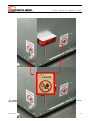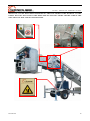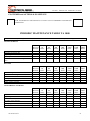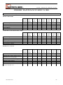
1
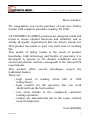
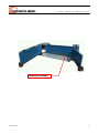
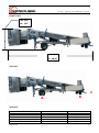
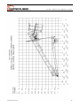
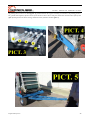
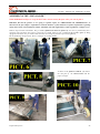
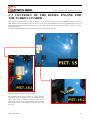
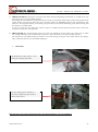
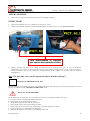
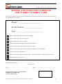
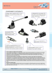
CIEMMECALABRIA S.R.L. Via Bonfadina, 111 25046 Cazzago San Martino (Brescia) - Italia Tel. 0039.030.72.54.118 r.a. Fax. 0039.030.7759992 www.ciemmecalabria.it “OWNER’S MANUAL” HYDRAULIC TURKEY LOADER TA 1000 AND SIMILAR MODELS (In conformity with the relevant basic safety and health requirements of EU Directive 2006/42/CE) TA 1000 - Manuale cod. TA0002 Rev. 03-2010 TABLE OF CONTENTS 1. INTRODUCTION “Dear Customer” Acquaintance with the machine The Turkey Loader ready to work Weight And Dimension Introduction Safety Labels pg. 2 pg. 3 pg. 5 pg. 6 pg. 7 pg. 10 2. SECTION “A” GENERAL INFORMATION A1: Identification of the machine pg. 14 3. SECTION “B” SAFETY INSTRUCTIONS B1: Duty B2: Psychophysical conditions requirements B3: Personal protection devices B4: Other important safety objects B5: Preparation for use B6: Safety suggestions pg. 16 pg. 16 pg. 17 pg. 17 pg. 17 pg. 18 4. SECTION “C” PREPARATION FOR USE C1: Unintended use C2: Preparing the machine C3: The diesel engine C4: Controls in the cabin C5: Optional equipment C6: Special Optional Equipment C6.1 Version without engine C7: Start up of machine and guide to setting C8: Working procedures C9: Tasks of the 2 operators inside the cabin C10: Statement of the main procedures C11: Disengagement of the machine C12: Road Circulation C13: Residual risks pg. 20 pg. 22 pg. 28 pg. 32 pg. 39 pg. 42 pg. 43 pg. 45 pg. 46 pg. 47 pg. 48 pg. 48 pg. 51 pg. 51 5. SECTION “D” THE MAINTENANCE D1: Introduction D2: Maintenance intervals D3: Storing the machine pg. 54 pg. 55 pg. 58 6. SECTION “E” GUARANTEE Table of contents E1: Guidelines for guarantee pg. 63 2 TA 1000 - Manuale cod. TA0002 Rev. 03-2010 INTRODUCTION Introduction 3 TA 1000 - Manuale cod. TA0002 Rev. 03-2010 Dear costumer, We congratulate you on the purchase of your new Turkey Loader with complete automatic loading TA 1000. All CIEMMECALABRIA products are designed, made and tested to ensure optimal functions and reliability and to satisfy all quality requirements that our factory stands out. This product has made to pass very hard tests of working life. This model of turkey loader is the result of product knowledge, high technology and facility of operation; it is developed to operate in all climatic conditions and its electrical hydraulic controls corresponds to the relevant CE requirements. This product offers several advantages respect the traditional loaders. These are: - high speed of loading (from 600 to 1300 turkey/hour); - high comfort for the operators that can work sheltered from the bad weather; - less stress thanks to the completely automatic loading operation; - turkeys are automatically put in the coops, without need of manpower. Your faithfully Introduction 4 TA 1000 - Manuale cod. TA0002 Rev. 03-2010 ACQUAINTANCE WITH THE MACHINE Main Tunnel Control Cabin Gathering preloader PART “a” Second Operator Zone PART “b” First Operator zone Caging belt Introduction 5 TA 1000 - Manuale cod. TA0002 Rev. 03-2010 Gathering prealoader Introduction 6 TA 1000 - Manuale cod. TA0002 Rev. 03-2010 THE TURKEY LOADER READY TO WORK Lifting cilynders of the cabin Hydraulic front stabilizers Introduction Parking Jacks 7 TA 1000 - Manuale cod. TA0002 Rev. 03-2010 DIMENSION Mt: 2,34 Ft: 7,67 Mt: 12,25 Ft: 40,19 WEIGHT C B A WEIGHT: MACHINE SECTION TOTAL WEIGHT WEIGHT ON THE “A” AXLE WEIGHT ON THE “B” AXLE WEIGHT ON THE “C” TOWING EYE Introduction KG LB 7.320 6.400 840 620 16,137.84 14,109.58 1,851.88 1,366.86 8 TA 1000 - Manuale cod. TA0002 Rev. 03-2010 INTRODUCTION This operation manual is meant for those concerned with the control, use and maintenance of this turkey loader. It contains all data required for a safe handling, use and maintenance of the machine. The manufacturer of this machine is the CIEMMECALABRIA S.R.L. that has his head office in Cazzago San Martino (Brescia) Via Bonfadina n° 111. Henceforth we will call this factory simply CIEMME. IMPORTANT Before operating, adjusting or servicing the machine it is important that the safety instructions in this manual are carefully read and understood. So, it is very important to read this manual carefully before using the machine and to keep it handy. In this way you will avoid accidents and always have a functional machine in perfect working order. Disregard of the instructions of this manual, inadequate maintenance, use of the machine other than for its intended purpose, or unauthorised modification of the turkey loader will render the CIEMME’s warranty and responsibility void. THIS MANUAL HAS 5 DIFFERENT SECTIONS: SECTION SECTION SECTION SECTION SECTION A B C D E GENERAL INFORMATION SAFETY INSTRUCTIONS PREPARATION FOR USE MAINTENANCE WARRANTY CONDITIONS IMPORTANT If after reading this manual, you still have doubts about the use of the machine, please contact CIEMME immediately; our operator will be at your disposal to give you every help and explanation needed to assure you optimum performance of your machine. In this operator manual you will find 3 different pictograms. They will help you in locating text passages, and are used to mark 3 different levels of potential risks. They are: DANGER! PAY PARTICULAR ATTENTION TO THIS SYMBOL. IT MEANS THAT THERE COULD BE A SERIOUS HAZARD TO LIFE AND HEALTH. IT EMPHASISES PRECAUTIONS THAT MUST BE COMPLIED WITH IN ORDER TO PREVENT ACCIDENTS. WARNING THIS SYMBOL REFERS TO TIPS FOR ASSEMBLY OR ADJUSTMENT THAT WILL NOT INCUR SERIOUS PERSONAL INJURY BUT CAN DAMAGE THE MACHINE. IMPORTANT THIS SYMBOL REFERS TO INFORMATION NEEDED FOR A BETTER UNDERSTANDING OF THE MACHINE AND TO MAKE THE WORK EASIER BUT THERE ISN’T ANY DANGER FOR THE PEOPLE AND THE APPLIANCE. Introduction 9 TA 1000 - Manuale cod. TA0002 Rev. 03-2010 PEOPLE MUST REMAIN AT A SAFE DISTANCE WEAR A SAFETY HELMET CAUTION: ELECTRICAL COMPONENTS WARNING! HANDS CAN BE CRUSHED BETWEEN MOVING PARTS: PINCH POINT BE ATTENTIVE, READ AND UNDERSTAND THE INSTRUCTION MANUAL BEFORE REPAIR OR OPERATION DON’T OPEN OR REMOVE THE GUARD BEFORE THE MACHINE IS STOPPED HANDS CAN GET CAUGHT IN Introduction FEET CAN BE CRUSHED 10 TA 1000 - Manuale cod. TA0002 Rev. 03-2010 SOME OF THE PICTOGRAMS YOU HAVE SEEN ARE PRESENT ALSO ON THE MACHINE AND CAN BE INTEGRATED WITH TEXT EXPLANATIONS AND INFORMATION. FOR A BETTER UNDERSTANDING OF THE MEANING OF THESE SYMBOLS, PLEASE READ THE CHAPTER “SAFETY LABELS”. IN THIS MANUAL, YOU WILL FIND ALSO OTHER PICTOGRAMS THAT REFER TO SPECIFIC OPERATIONS. READ THROUGH THE MANUAL CAREFULLY BEFORE USE OR ASSEMBLY AND IF YOU AREN’T SURE OR IF YOU HAVE DOUBTS DON’T START ANY OPERATION AND STOP IMMEDIATELY. IF DURING THE WORK YOU NEED AN ASSISTANT, ON THE GROUND OR ON THE MACHINE, BE SURE THAT YOU CAN ALWAYS SEE HIM AND THAT ALL OPERATIONS WILL BE MADE WITH COMMANDS BOTH GESTURAL AND VOCAL. BE SURE THAT ALL COMMANDS WILL BE UNDERSTOOD AND THAT YOUR ORDER ALWAYS MUST BE FOLLOWED BY A CONFIRMATION OF YOUR ASSISTANT. DON’T START ANY OPERATION UNTIL YOUR ASSISTANT WILL GIVE YOU HIS CONSENT TO OPERATE AND UNTIL HE AUTHORIZES YOUR ACTION. BE AWARE OF YOUR RESPONSIBILITY. CARELESSNESS OR SLOVENLINESS CAN CAUSE SERIOUS INJURY OR DEATH. AFTER READING THIS MANUAL, CONSULT CAREFULLY THE CHAPTER “RESIDUAL RISKS AND SUPPLEMENTARY SAFETY REGULATIONS” THAT YOU WILL FIND ON CHAPTER C.13 OF THIS MANUAL. Introduction 11 TA 1000 - Manuale cod. TA0002 Rev. 03-2010 SAFETY LABELS To help you to find the safety labels on the machine, the following photos show the areas where the stickers are located. Make sure that this manual is always made available and keep safety decals and signs clean and legible at all times. If safety decals and signs are missing or have become illegible, contact the manufacturer for replacements immediately. Don’t start working until the label is installed or replaced and be sure that the replacement part also displays the current decal or sign. LABELS IN THE CABIN Introduction 12 TA 1000 - Manuale cod. TA0002 Rev. 03-2010 ALL LABELS POSITIONED ON THE RIGHT SIDE OF THE CABIN ARE THE SAME AS THE ONES POSITIONED ON THE LEFT SIDE. Introduction 13 TA 1000 - Manuale cod. TA0002 Rev. 03-2010 BELOW YOU CAN SEE THE LABELS POSITIONED ON THE MAIN FRAME OF THE MACHINE. ALL THE LABELS THAT YOU WILL FIND ON THE RIGHT SIDE OF THE MAIN FRAME ARE THE SAME OF THE ONES THAT YOU WILL FIND ON THE LEFT SIDE. Introduction 14 TA 1000 - Manuale cod. TA0002 Rev. 03-2010 SECTION A GENERAL INFORMATION General information 15 TA 1000 - Manuale cod. TA0002 Rev. 03-2010 A.1 DENTIFICATION OF THE MACHINE On the right frame of the machine is located the Identification Plates as required by the Department of Transportation and also from the e DPR 459/96 (next picture). Over there is also indicated the Manufacturer of the machine. Serial Number Building Date Contents of the picture: 1 – Authorised people only. This machine may be used by authorised and qualified people only. You are responsible for the safe operation and maintenance of your machine. You must ensure that you and anyone else who is going to operate, maintain or work around the unit be familiar with the operating and maintenance procedures and related safety information contained in this manual. 2 – Before starting to operate the machine, always check that the levels for the motor oil, hydraulic oil and the water in the radiator are correct. Always verify that all filters and prefilters are cleaned. Always verify the tension of the belts. 3 – All operations of maintenace must be done with machine guards open. Shut off the engine and remove the key before performing maintenance or repair work. 4 – Only operate the machine when each guard and shield is complete, intact and placed in its functional position! 5 – Keep a safe distance from the running machine 6 – Keep a safe distance from the several moving and lifting parts 7 – Operators are never to leave their control position and they must use personal protections devices as provided for by law. 8 – In case of break-down, immediately contact the manufacturer or authorized. Only CIEMME or Dealer technicians are authorised to repair the machine. Repair work must only be carried out by professionals with the correct fitting equipment! 9 – Before working on the electrical device and switchboard panels, separate these from the electric power supply. Supplies being charged can cause material or personal damages. 10 – Don’t clean electrical components like switchboard panels and control boxes with water, steam or additives. 11 – All welding work on the machine is prohibited 12 – Disregard of the instructions found in this manual, inadequate maintenance, use of the machine other than for its intended purpose, or unauthorised modification of the machine render the CIEMME’s warranty and responsibility void. Respect the maximum load permitted as reported on the plate and verify that your transport vehicle is adequate for the task. Adhere to the maximum permissible transport dimensions! In case of any questions, general information and/or technical assistance it is necessary state precisely the model of machine, its code and the serial number that you find on the plate. General information 16 TA 1000 - Manuale cod. TA0002 Rev. 03-2010 SECTION B SAFETY Safety 17 TA 1000 - Manuale cod. TA0002 Rev. 03-2010 To put into function correctly the machine read carefully this manual. To avoid many accidents follow the instructions reported in this manual. Check periodically that the machine during the operation satisfy the safety requirements. Take care that the operator has good knowledge of all the risks deriving from the improper usage of the machine. B.1 DUTY Persons under 18 are strictly forbidden to use the machine. While working the crew is composed by two (02) operators: define clearly who is the Foreman and who the assistant is. The machine can’t be used by less that two (02) workers. The FOREMAN can’t start any operation without receiving the confirmation by the ASSISTANT that the order has been understood. Do not remove the safety protections, the safety labels and the warning plates, if unreadable replace them promptly. B.2 OPERATORS PHYSIC WORKING CONDITION Operators can use the machine just in case having the following conditions : PHISIC CONDTIONS: Good sight, hearing, coordination and ability to perform all the tasks required to the machine’s operators. MENTAL REQUIREMENTS: Ability to follow prevention advices. Being attentive and work paying attention to the good common sense to preserve third people safety and yours. Perform correctly and scrupulously your work EMOTIONAL: Being patient and being able to keep the calm, work paying attention to the common sense to evaluate their own conditions. TRAINING: Reading and reviewing carefully the machine’s manual before operating any hydraulic lever. Having knowledge of the operative limits. Safety 18 TA 1000 - Manuale cod. TA0002 Rev. 03-2010 REST - WORK SHIFTS: RESPECT WORK FARM/COMPANY/PROCESSING PRESCRIBED. AND REST SHIFTS AS FROM THE B.3 PERSONAL PROTECTION DEVICES While working, servicing and repairing always wear proper wear clothes to avoid any kind of accident. In particular always wear: WORK GLOOVES SAFETY SHOES PROTECTIVE HELMET WORK GLASSES CAP FOR THE HAIR ANTIDUST MASK JUST USE APPROVED ACCIDENT PREVENTION MATERIAL B.4 OTHER IMPORTANT SAFETY OBJECTS Keep always handy following items: FIRST-AID KIT FIRST AID NUMBERS (ambulance, hospital, police i.e.) Safety 19 TA 1000 - Manuale cod. TA0002 Rev. 03-2010 B.5 PREPARATION FOR USE Before or durign the operation never drink alcol, take medicines, drugs or any substance that can limit the ability to operate the machine. B.6 SAFETY SUGGESTIONS - Under are listed some important advices to protect third people or operator safety, please follow them scrupulousy. - Keep handy this manual, learn to work the machine in the proper safest way. - Usually the machine is towed by vehicles having a diesel combustion engine. Never work inside. - Combustions fumes can be lethal - Park the machine on even round with the machine on the lowest position. Do not move the machine while persons are in the action ray, a sudden moving can cause an accident. - Never work in case of excessive slopes, the machine stability could be prejudiced. - Pay attention that in the action ray there are no bystanders or children in particolar.. If there are never operate the machine till when they have a minimum distance of 10 (ten) meters inside a sheltered area. - Perform any operation while the engine is switched off, the machine has to be in stand-by (also when is lifted), be sure that there are no residual pressures in the system. - Do not change the high-pressure valve tare , or the cabin end-off the stroke. - Oil leakages if in presence of pressare can cause injuries, evaluations and reasearches have to be done with the proper clothes: gloves, protective glasses or protective shields. - Operate prudently in presence of power lines. - Take in mind that electrocution can also happen without contact, distances varies according to the power line. - Do not transfer the machine while the cabin is not in right position. Be sure the cabin is fully in with the locks in to keep the right cabin height from the ground. - Learn well the vehicle controls, even if having under this manual it’s very important to know them to operate the machine. No doubt or mistake is allowed - Pay attention that in the machine action ray there are no bystanders, no people inside the barriers are allowed. - During transfers do not bump into the trailer’s roof or into the truck: can be very dangerous for operators. - Do not modify safety devices. - Do not wear jowels or any other object that can be hanged from the machine, keep well closed the cuffs and collars overhaul. Never use scarves and/or handkerchieves to protect yourself against dust weat always the protective caps. Safety 20 TA 1000 - Manuale cod. TA0002 Rev. 03-2010 SECTION C PREPARATION FOR USE Preparation for use 21 TA 1000 - Manuale cod. TA0002 Rev. 03-2010 C.1 NOT INTENDED USE This turkey loader with complete automatic loading is exclusively and appropriately designed and manufactured for the loading of turkeys from a collecting area to a purposely equipped truck. Disregarding the safety instructions, inadequate maintenance, use of the machine other than for its intended purpose, overloading or unauthorized modification of the machine, will render the manufacturer’s warranty and responsibility void. Untrained or unauthorized members of staff may not use, maintain or repair the machine. Always respect all safety instructions for the prevention of accidents and adhere to the regulations of the Highway Code when using a public road. Look around the machine before driving off and before switching on the machine. Never remove a component without referring to the relevant procedure. Never carry out modifications without prior consent of the manufacturer. DANGER For safety reasons and for having the best performance use only original spare parts. CIEMME is not liable to pay any damages if they are the result of using “non original” spare parts. PREPARING AND USING THE MACHINE The machine is appropriately designed and made for loading particular and specific goods, turkeys, and it must operate in marked areas limited by barriers. Barriers have the purpose keep unauthorized people out of the working area. Never start to operate until this task is completely done. Barrier are not supply from CIEMME. For more information go to chapter C.2 and see the picture 1. The machine, for the particular nature of the goods to work, was deliberately designed and manufactured without certain protection guards in place that would normally protect people from potentially dangerous components like rollers, bearings or belts. This absence is justified by the necessity to regularly wash and use bactericides on the machine to avoid the propagation of poultry illnesses. Therefore, when the machine is running, the barriers which limit access to the dangerous area have the same function and effect as machinery guards and protect people in the same way that actual guards would. Once positioned and started, it is strictly forbidden for anyone to stand in the marked working area. This marked area mustn’t be crossed. If necessary, people must ask permission of the foreman to enter the dangerous working area. The foreman must stop the machine and the work before granting such permission. In the following picture, you can see the limits of the danger area that must be controlled. Preparation for use 22 TA 1000 - Manuale cod. TA0002 Rev. 03-2010 Picture 1 Safety Area, do not cross Truck Safety Area, do not cross Preparation for use 23 TA 1000 - Manuale cod. TA0002 Rev. 03-2010 C.2 PREPARING THE MACHINE The machine is normally trailed to the farm by a specifically equipped vehicle. Then, to place the turkey loader in the right working position you have to follow these instructions: The staff necessary for the preparation of the machine consists of 2 operators: the foreman and the assistant. There will be no doubt on who will be the leader and who will be the assistant. Without this distinction, no action will be executed. The leader never may start any operation, like the ones subsequently explained, if he is not sure that his assistant has understood and he is ready to work. During the operation for the preparation of the machine in the working area, execute only the actions required for the parking and standing of the machine. During this phase it is strictly forbidden operate keys and switches for raising/lowering the cabin and for unrolling the belts. Avoid every actions not described in this manual. It is necessary to follow only the instructions found in this manual and not different procedures. Doing procedures and operations not directed in this manual render the manufacturer responsibility void. N.B.: Positioning the machine by following the described procedures in the order you find them. POSITIONING THE MACHINE ON A FIRM AND LEVEL AREA To place and park the machine in its start position it may be necessary for the driver to use the reverse gear. During this operation, the trucker must follow all dispositions described in the chapter B and it is also necessary for a helper to guide him during cornering and the maneuvering. His assistant must also verify that there are no people in the ray of (at least) 10 meters.(33 ft.). Special care shall be taken when parking and unhitching the machine from the truck. Park the machine on a firm, dry and level area. This will lessen the possibility of tipping and/or sinking into soft and slippery ground or mud. Once the machine is in its start position and once all parking procedures have been executed (see the section A of this manual) disconnect the machine from the transport vehicle in conformity with the safety instruction described in the sections A and B of this manual. Now you are ready for the second operation: ATTENTION: Go to next page and observe the diagram with the dimensions of the turkey loader TA 1000. While parking the machine in the room, be sure that the height of the machine is less than the height of the ceiling joist!!! UNHITCHING THE DRAWBAR ATTENTION: Before any operation, CONNECT THE CONNECTOR (picture 19 Chapter C.3). First point: the machine is equipped with the internal-combustion engine. Start the engine by turning on the key that you find on the control board (fig.1). Start the electrical circuit by pushing the blue button that you find in the cabin (fig. 2). The other 2 buttons you see in picture are: the white one is the switch to turn on the headlights of the cabin while the red one is the emergency stop button. We will deal with them in the following chapters. Preparation for use 24 TA 1000 - Manuale cod. TA0002 Rev. 03-2010 Preparation for use 25 TA 1000 - Manuale cod. TA0002 Rev. 03-2010 By pushing down on the lever (N°1 of pict. 3) positioned under the engine assembly you will lower the parking jacks to the ground and completely lift the wheels of the drawbar. Then remove lock pins mounted on both the sides of the frame (pict. 4) and pull out the thrust bearing and the drawbar from the machine (pict. 5). Preparation for use 26 TA 1000 - Manuale cod. TA0002 Rev. 03-2010 ASSEMBLING THE “PRE LOADER” VERY IMPORTANT: Before to set up the Pre Loader clean accurately the floor where you want to park it. Remember that all the pictures we are going to explain require an “AREA/SCOPE OF COMPETENCE” as discussed in the first chapter “Acquaintance with the machine” of this manual. For further information regarding safety and security read carefully the chapter “Residual risks and supplementary safety regulations” (Chapter C.13). Remove all protections and blocks. The pre loader (foldered as shown in picture 6) can now be positioned by the 2 operators. The operators have only to grasp the pre loader frame by the 2 outboard side handles (pict. 7). Being equipped with wheels, the pre loader will run on the soil easing the placement operation) (pict. 8). Be careful during this operation. There is a danger of crushing hands! As shown in the pictures 9 and 10 , lift and set the end part of the PRELOADER with the proper lock pin. Preparation for use 27 TA 1000 - Manuale cod. TA0002 Rev. 03-2010 Opening the 4 climbing ramps of the PRE LOADER (picture 11). Remove the 3 shields positioned above the tunnel of the turkey loader (picture 12). Now is possible to mount the BOX as shown in the picture 13 and position 2 of the 3 shields as shown: one on the left side and the other on the right side of the end part of the pre loader. Preparation for use 28 TA 1000 - Manuale cod. TA0002 Rev. 03-2010 Now the preloader is correctly mounted, as you can see in the picture 14. For further safety information read carefully the chapter “Residual risks and supplementary safety regulations” found chapter C.13 of this manual. Next to the tunnel there is an oil flow limiter to control/regulate the speed of the belt of the PRE LOADER. Turn it clockwise to increase the speed and counterclockwise to decrease the speed (Pict. 14/1). Never raise the speed of the belt of the pre loader more than the half of the speed of the tunnel belt! Preparation for use 29 TA 1000 - Manuale cod. TA0002 Rev. 03-2010 C.3 CONTROLS OF THE DIESEL ENGINE FOR THE TURKEY LOADER . The engine is connected to a 12 V and 75 A/H battery. On the engine bonnet, as shown in picture 15, there is a switch (pict. 15.2) to connect and disconnect the battery to the engine. The YELLOW connecting plug (pict. 15.1) is used for preheating the hydraulic oil and the motor water. This 2 pin plug of 110 Volt and 16 Ampere can be used in case of very cold temperatures. During cold conditions preheat for 4/5 hours before working with the machine. (TA1M15) Engine oil/engine water pre-heater. This optional allows to keep steady the engine oil/water temperature while the machine is not in operation parked under cold weather conditions and the engine is not running. We suggest to put this optional into function when the temperature where the machine is parked is lower than 0 C°/32F. Preparation for use 30 TA 1000 - Manuale cod. TA0002 Rev. 03-2010 DO NOT ATTEMPT TO START THE ENGINE UNLESS THE SWITCH IN PICT. 15 HAS BEEN TURNED ON AND THE CONNECTOR IN PICT. 18 & 19 HAS BEEN INSERTED. Picture 16 shown the engine control panel composed by: 1. 2. 3. 4. 5. 6. Engine Rpm Engine Water temperature Fuel Gauge Safety key (pay attention) Start key Pilot light Indicator: A= B= C= D= E= F= G= H= Battery Engine Oil Engine Water No Function Glow Plug Oil Filter Obstruction Hight Pressure Emergency in Fuel Gauge Reservoir Turn the ignition key to the ON position (one click to the right). The oil pressure light and the battery light should burn bright red. One more click of the switch will turn on the yellow glow plug light. One additional turn of the switch will engage the engine starter. The battery light and the oil light should go out. Unblock the emergency stops, 2 in the cabin (1 on each side) and 1 at the end of the of the tunnel (pict. 17). Preparation for use 31 TA 1000 - Manuale cod. TA0002 Rev. 03-2010 Below you can see the picture of the connector and the electric connection cable (pict. 18 and 19). CIEMMECALABRIA along with the loader supply the cable (pict. 19) with numerated wirings to be connected as from the table under. Connect the wirings with the plug (Pict. 18) according to your needs and connect the plug (picture 19.1) to your towing vehicle. Wiring Table Cable Nr. 1 2 3 4 5 6 7 8 9 Y/G Preparation for use Description EARTH YELLOW BRAKING ACTUATOR HEADLIGHT + TAILLIGHTS POSITIVE LEFT STOPLIGHT RIGHT STOPLIGHT LEFT TURNLIGHT RIGHT TURNLIGHT BLUE BRAKING ACTUATOR FREE SPARE 32 TA 1000 - Manuale cod. TA0002 Rev. 03-2010 In the picture 22 are shown the levers which control the most important operations of the turkey loader TA 1000. These controls are situated beside the main frame of the machine and more precisely under the engine assembly. There are 4 hydraulic controls (levers) which each have 2 functions (UP and DOWN). The handle N° 5 is used to engage and disengage the traction control transmission. The control levers operate the following functions: Pushing downwards on lever N° 1 of pict. 22 the front hydraulic stabilizers (for the extraction of the thrust bearing and the drawbar) will extend to a lowered position. This operation was described in chapter C.2 of the manual. Pulling upwards on lever N° 1 the hydraulic stabilizers will retract to the original position. Pushing downwards on lever N° 2 of the picture, the machine will go backwards in the direction of the cabin. Pulling upwards on this lever, the machine will move forward. Clearly, the second operator will give direction to the machine guiding with the drawbar as explained in chapter C.2 (see the picture 5). ATTENTION: Be careful during the tow bar direction uneven ground can provoke sudden moving of the tow bar itself injuring the operator. ATTENTION: this operation is allowed only when the traction lever control N° 5 is positioned (CLOSED) as shown in the picture 22.1. If you want to transport the machine with a tractor vehicle, you must put the lever 5 in the opposite position (OPEN), like picture 22.2. TA1M10 MAIN AXLE TRANSMISSION TA1M10 (optional) is used for the small machine transfers inside the farm. How to put it into function: 1. Move the lever towards “Close”; 2. Then act on the valve body lever N2 (pict. 22). Preparation for use 33 TA 1000 - Manuale cod. TA0002 Rev. 03-2010 There are 2 other hydraulic parking jacks positioned in the rear of the machine (pict. 23). The first one (letter A picture 2) is controlled by the lever number 3 (pict. 22), the second one is controlled by the lever number 4 (pict. 22). These hydraulic stabilizers have the function of placing the machine on the ground safety during the working operations. IMPORTANT: Position the machine on a dry and level area and be sure that there isn’t soft ground or mud. During work, the wheels should not be in contact with the ground. The adjustment of the wheels may be carried out by placing the parking jacks in different vertical positions. C.4 CONTROLS ON THE CABIN Once set up and leveled the TA 1000 turkey loader is operated and controlled from the cabin. It must be determined, without doubt, who is to be the Leader/Foreman and who is/are to be the assistant/s. The leader will operate from the control area as shown in the picture 24. From this position, he can use all the control commands we are going to describe and explain. To work correctly and in safety it is necessary for another Operator to work on the opposite side of the cabin: he has the simple task of opening/closing the coops. All other control and tasks are the prerogative of the leader. The only control command accessible to the assistant is the emergency stop. There are 3 emergency stop buttons: two in the cabin (one each side) and one in the end part of the machine. Pushing any one of these buttons will cause any and all processes and activities to be immediately interrupted. Preparation for use 34 TA 1000 - Manuale cod. TA0002 Rev. 03-2010 The TA 1000 turkey loader has the follow control commands: The speed of the belts may be adjusted using the flow limiters shown in the picture 25. The flow limiter N° 1 is for the main belt belt. The flow limiter N° 2 regulate the speed of the cage belt. ATTENTION: the cage belt speed must NEVER be less than the speed of the main belt. The foreman/operators leader has the total responsibility of the running of main belt inside the tunnel. To operate, pushing gently the pedal you will find on the floor of the cabin near your feet. Stepping on the pedal, the main belt will start working; raising the foot from the pedal the main belt will stop (pict. 26). Preparation for use 35 TA 1000 - Manuale cod. TA0002 Rev. 03-2010 The cage belt is controlled by the handle shown in pict. 27. Moving the handle upwards starts the cage belt. To stop the belt, bring the lever back to its original position. Inside the cabin there are also 2 control levers (“1” & “2” pict. 28) each of which can be positioned in 4 different settings. See below to learn their use: Preparation for use 36 TA 1000 - Manuale cod. TA0002 Rev. 03-2010 The lever 1 of picture 28 can be moved into 4 different positions: A & B: with these 2 controls it is possible to maintain the cabin always parallel in respect to the coop’s floor (pictures 29;30;31).Putting the lever in position “A” the cabin is tilted up, while in position “B” the cabin is tilted down. A C D B Preparation for use 37 TA 1000 - Manuale cod. TA0002 Rev. 03-2010 C & D: operating with these 2 controls the cabin will be raised or lowered (pict. 32). A C D B 2 lifting cylinders allow the raising and lowering of the cabin Preparation for use 38 TA 1000 - Manuale cod. TA0002 Rev. 03-2010 The lever 2 of picture 28 can be moved to 4 different positions: Placing the lever in the positions A1 & B1 the cabin will approach or back away from the truck. Position “A1” to extend the cabin (forward), position “B1” to pull the cabin back (reverse). See pictures 34; 35; 36. A1 C1 D1 B1 Preparation for use 39 TA 1000 - Manuale cod. TA0002 Rev. 03-2010 A1 D1 C1 C1 & D1 are the controls which allow us to the extend the caging belt into and retract out of the coops on the transport trailer. “C1” the caging belt extends (forward) “D1” the caging belt retracts to its original position (reverse) Look the pictures 37, 38, 39 B1 The caging belt is full retracted (pict. 37). The caging belt is in its full extension (pict. 39). Preparation for use 40 TA 1000 - Manuale cod. TA0002 Rev. 03-2010 C.5 GAUGES AND OPTIONAL EQUIPMENT PARTICULAR OPTIONAL EQUIPMENT All hydraulic controls, for operating, need of an electrical input (chapter C.2 pict. 2). However there is an exception: Near the motor switchboard panel (pict. 40) there is a keyhole block. Turning the apposite key is possible leaving out the electrical system and permitting to operate and work with the machine without electrical inputs after the ignition. Keyhole block BE CAREFUL: The key of this block must be put in a safe place, far from untrained or unauthorized people. This Key can be used only during operations of exceptional maintenance and only with prior consent of the manufacturer and from personnel trained in the use of this device. Scope of this key is to disconnect all the emergency electrical circuit in case of brake down on it, and allow to keep the engine running till the necessary time to take off the machine from the shed. When the key is in position one all the security push bottom are out of order and the engine can’t be shut off through this buttons. The warranty will be automatically annulled if these dispositions will not respected. CIEMME isn’t liable for compensation of any damage as a result of wrongful or irresponsible use of the machine and its equipment. Preparation for use 41 TA 1000 - Manuale cod. TA0002 Rev. 03-2010 C.6 SPECIAL OPTIONAL EQUIPMENT “TA1M19” PTO CONNECTOR Ta 1000 can be supplied with the optional TA1M19, the PTO quick connect set. ONLY trained/authorized people can use this optional during the extraordinary maintenance after being previously authorized by the machine manufacturer or from the personnel trained in using this device. To be used just in case of machine brake down to take the machine out off the shed. When PTO QUICK CONNECT IS SET UP all the emergency push bottom are out of order, only trained or authorized people can operate with the machine after set up it. Warranty will be void if the rules over are not strictly followed. CIEMME is NOT liable for compensation of any damage as a result of wrongful or irresponsible use of the machine and its equipment. How connect the TA1M19, to the PTO quick connect set: Engine MUST be down and the start key out of control box. Connect the 4 pipes of the optional on this way: The 2 suction pipes must be connected with the 2 tank connection (pict. 40.1) and open the two taps on this fittings (see same picture vertical size). Be sure connecting the pipes correctly because pumps are different. After checking that connections are correctly done connect the PTO block to the tractor PTO through the provided system block (pict. 40.2), tractor must be off, start up the tractor and PTO (540Ppto running) and rise the engine tractor to 1500 RPM. Attention: when you disconnect the quick connect (TA1M19), close the two taps (pict. 40.3) and keep the parts into a safety place under control by personnel trained in the use of this device. Taps need be horizontally turned while the connection/disconnection from the hydraulic system. Turn them vertically to put in function the loader through the PTO tractor. At the end of the work, before disconnecting hydraulic pipes, do not forget to turn horizontally all the 04 taps. Preparation for use 42 TA 1000 - Manuale cod. TA0002 Rev. 03-2010 C.6.1 VERSION WITHOUT ENGINE The TA1000 without engine, has the hydraulic tubings connected directly to the tractor When the turkey’s loading operation is finished, Hydraulic lines must be disconnected from the tractor and put on the machine using the supplied brackets Preparation for use 43 TA 1000 - Manuale cod. TA0002 Rev. 03-2010 To do this operation you must transit in front of the machine passing the tubing below same machine It is strictly forbidden go under the machine to wrap the pipes supplied brackets Fix the tubing with screw follow the reverse procedure for connect the tubes to the tractor Preparation for use 44 TA 1000 - Manuale cod. TA0002 Rev. 03-2010 C.7 START UP OF MACHINE AND GUIDE TO SETTINGS By now we have familiarized ourselves with the machine and we know its main accessories and components. Now we will explain how to use and work with the turkey loader to assure the best performance. If you aren’t sure that you understand the previous information and recommendations don’t continue. Before reading this section, just try to answer to the following questions: What is the correct operation to park and set up the machine for loading? How many controls are necessary to work the machine? Are you able to find them? What are the best conditions to operate with the turkey loader? What are the Personal Protection Devices that all operators always must wear? Make a list of (at least) 10 components of the turkey loader. List and explain the function of all indicator lights on the switchboard panel and their color. Do you take off the drawbar or the pre loader first? Who is the foreman/leader? What are the crash barriers? Where do you place them? If you answered exactly, satisfactorily and without doubts and checked the answers as written in the previous chapters, you are ready to continue to learn the use of the controls in the cabin and on the pre loader. C.8 WORKING PROCEDURES After reading and learning the things we have previously explained, it is possible to continue discussing the remaining procedures and operations used to work the turkey loader for best performance. Summarizing the most important information discussed until now : The machine conforms to the relevant requirements of EU directive 89/392 in accordance with the operating procedures and related safety information contained in this manual. Be sure that controls, indicator lights and emergency stop buttons work correctly and that the transport truck is in safe operating condition with adequate braking and lifting/pulling capabilities for a machine of this size. Ensure sufficient visibility during all operation and transport. The machine may be used only by authorised people with adequate clothes and wearing the personal protection devices described in the section B. Only if all these conditions are fulfilled then you can start to work. Preparation for use 45 TA 1000 - Manuale cod. TA0002 Rev. 03-2010 IMPORTANT C.9 TASKS OF THE 2 OPERATORS INSIDE THE CABIN The 2 operators inside the cabin (Foreman/leader and his assistant) must coordinate their own jobs to reduce to a minimum any misunderstanding that could cause harm to people or goods. The controls are in the hands of the foreman (situated in the part “a” of the cabin as shown in the picture 45) who carries on these main operations: lifting and lowering the cabin; tilting up and down the cabin; extending/withdrawing the caging belt and the telescopic device of the cabin; starting/running/stopping the pre loader belt, the main belt and the caging belt. The assistant inside the cabin is situated on the opposite side (side “b” of the cabin as shown in the picture 39 area 1). He has only the task to open/close the crates. During this operation, the leader may never touch the controls or set in move any components of the machine until he has given his assistant the time to open/close the crates of the container. Side “a” of the cabin Side “b” of the cabin Both the operators inside the cabin have access to an emergency stop button. They may push it at any moment and for any reason it becomes necessary to stop the loading operation. Both the operators must apply and insist upon application of the instructions contained in this manual. They must not take the initiative and/or engage in actions not described here. Except for the emergency stop, be sure that the colleague has understood the action you’re going to do and wait his consent before operating. Preparation for use 46 TA 1000 - Manuale cod. TA0002 Rev. 03-2010 The disregard of these instructions and use of the machine other than for its intended purpose will reduce the CIEMME responsibility and make the warranty null and void. Don’t run the risk of serious or fatal accidents through ignorance of our instructions. Obviously, all operations described until now may be carried out only if workers are inside the cabin. The cabin is supplied with lifting equipment and may reach several levels of height. However, the platform on which the operators stand can never exceed the 3 metres from the ground. Getting into/out the machine must only be accomplished when the platform of the cabin is at a height of 30 centimetres (12 inches) from the soil. Preparation for use 47 TA 1000 - Manuale cod. TA0002 Rev. 03-2010 C.10 STATEMENT OF THE MAIN PROCEDURES FOR OPERATING AND WORKING WITH THE MACHINE By now we have learned how to prepare the machine, what its components and equipment are, and how to operate it from the cabin and from the box. We have also learned that this machine is exclusively and appropriately designed and manufactured to collect and load poultry from a collecting area. Now we will discuss the main operating procedures and how to ensure an optimal and safe operation: The foreman/leader, before he gets into the cabin, must check that the danger zone is bounded with the appropriate barriers, is free from the presence of unauthorized people (bystanders, especially children) and, obtain the consent to start from his assistants. Considering the 3 operators: Foreman inside the cabin (side “a” of the cabin as shown in the picture 45). Assistant inside the cabin (side “b” of the cabin as shown in the picture 46). Assistant on the ground at the pre loader controls (picture 46/1). Are in the right operating positions. It is now OK to carry out the following instructions: 1. The foreman/leader, gets into the machine and tests the main functions of the turkey loader: Verify the running, and extend/retract functions of the charger and the main belt; Verify the functioning of the 3 emergency stop buttons (chapter C.3, pic. 17); Verify the working of the lights and the horn (chapter C.2). 2. After the pre-check, the foreman informs his colleagues that the machine is ready to work; he calls “READY”, waits for “GO” from ground and cabin assistants and finally calls “START”. 3. Now the machine is ready to work: the assistant on the ground may set free and get together the poultry in the collecting area and the loading operation may start. IMPORTANT: Follow rigorously these instructions: if during one process the result isn’t fully positive, repeat the whole procedure. Never start a new process if the previous one has turned out badly. C.11 DISENGAGEMENT OF THE MACHINE The disengagement of the machine may happen for 2 reasons: Transport Storage Trasport: Before transport will take place, please read the following safety information. The compliance is prescribed and helps you to avoid accidents. Before starting the transport, check the environment around you and always make sure that there is a clear view. Put the machine in the correct position. Make sure that there is sufficient steering, driving and braking capacity. It is your responsibility to ensure that there is appropriate lighting and luminous safety labels on the machine when it is being transported on public highways. Check always the tyre pressure. Comply with local legislation for driving on the roads. Parking and storage: When the loading operation is finished and there will be no work for a long time, you can begin the preparation for the storage of the machine. Observing the rules below, you will have a fully operational machine at the start of the next working operation. Therefore, check all points mentioned in the section concerning “MAINTENANCE“. Before placing the machine into service again, all adjustment activities described in this manual must be carried out. Preparation for use 48 TA 1000 - Manuale cod. TA0002 Rev. 03-2010 DISENGAGEMENT PROCEDURES: 1. BEFORE removing the barriers around the collecting area, the foreman, or another authorized and competent person, may start to remove the PRE LOADER making sure that the hydraulic circuit is not under pressure and disconnect the hydraulic couplings (picture 49). Than he will dismount the shields (pict. 50) and finish the first phase by folding the pre loader (as shown in the picture 51). Preparation for use 49 TA 1000 - Manuale cod. TA0002 Rev. 03-2010 2. Lower the hydraulic parking jacks (pict. 52/A) through the lever N° 1 shown in the picture 52. Reposition the thrust bearing and lock it with the lock pins (pict. 53). Than, always through the lever N° 1 (picture 52), raise the parking jacks to the full up position. In this way, the pads will be raised from the ground and it will be possible to start moving the machine. 1. Now, through the lever N° 2 shown in the picture 54, it is possible to move the machine forward (shifting the lever into the up position) or backward (shifting the lever into the down position). The controls will be operated by the foreman only, while his assistant will manoeuvre the drawbar to give the desired direction to the machine. The machine is now ready for transport or for storage. Only now is it permissible to remove the barriers. If there is any hydraulic oil stain on the soil, it will be necessary to clean it up with appropriate products. Preparation for use 50 TA 1000 - Manuale cod. TA0002 Rev. 03-2010 C.12 Road circulation (just for machines having the optional TA1M14) The road circulation is only allowed in case the machine has been equipped with the optional TA1M14: road circulation kit. Please be sure to check all federal, state, and local towing vehicle requirements before towing the loader on any public road (see on chapter overall dimensions and weight of the machine). To connect the machine follow the instructions hereinafter in case after reading your doubts persist contact the loader manufacturer to get more info. 1. 2. 3. Be sure the towing vehicle meets all the requirements before starting the moving in particular check the federal, state, and local laws. (see on chapter overall dimensions and weight of the machine). Be sure the machine is parked on a even ground with the safety wedges under the front wheels and be sure the front stabilizers are fully up (pict. 55) Be sure the transmission lever “5” (pict. 56) (you have just in case the loader is equipped with the optional (TA1M10) is in neutral position locked through the provided lock. (OPEN POSITION). Preparation for use 51 TA 1000 - Manuale cod. TA0002 Rev. 03-2010 4. Be sure the cabin is fully in and lift the front stabilizers (pict. 57). Have the provided rams locks in to keep the right cabin height from the ground during the transport (pict. 58). 5. Lift the back stabilizers to the proper height (pict. 59) to hitch the loader to the towing vehicle once it is hitched in the proper position lift back stabilizers (pict. 59) and be sure the hitch ball is correctly connected (pict. 59.2 and 5.3). Connect the safety chains (pict. 59.4) (No 02) and the electrical plug (see on chapter C.3). Preparation for use 52 TA 1000 - Manuale cod. TA0002 Rev. 03-2010 6. Take off the wedges from the front wheels (pict. 60) and start the transport. Preparation for use 53 TA 1000 - Manuale cod. TA0002 Rev. 03-2010 C.13 RESIDUAL RISKS AND SUPPLEMENTARY SAFETY REGULATIONS To safeguard the health of the people which work with the machine, in this section we will explain several fundamental rules. This instructions must be read, learned and/or taught to all personnel employed, be they the foreman or his assistant/s. Remember that the assistants may be more than one. In spite of the safety instructions and operating instructions contained in this manual, the protection devices and guards, and the installed warning and advisory signs, some risks still remain. There are, in fact, some “AREAS” which requires constant and special attention and caution. For this reason, every employee must be given training on use this machine. Remember that all mounting, working, transport, storage and maintenance operations must be carried out each and every time by at least two operators. One of them will be the Foreman/leader and will be responsible for all operations carried out with the turkey loader. The other/others will be his assistant/assistants and will follow his instructions. 1. CABIN: This is the part of the machine where the operators (the foreman and the cabin assistant) carry out the main functions and operations of the machine. It consists of a steel structure and a caging belt. This belt is telescopic (slides on two guides) and serves for putting the animals into the crates. The assistant who works in the side “b” of the cabin has the task to open/close the crates doors. To carry out this job, he will work in proximity of the caging belt. Be especially careful during this operation. Keep sufficient distance from the caging belt and don’t remove protective covers. WARNING: danger of crushing and cutting arms and hands. The cabin has the capability to work from 2 to 9.5 metres from the soil. For this reason, on the machine was mounted specific security devices to protect the operators from a fall. They are mounted near the access doors and must not be removed, modified or damaged. The cabin is also equipped with doors having a mechanical closing device. It is very important that the safety catches aren’t removed or damaged, because they prevent the operators from leaning out of the cabin running serious risk of serious or deadly injury. During the lowering operation, be sure that no one is standing under the cabin and near the tunnel and the main frame. During this operation, the risk of crushing is very high. ATTENTION: Do Not move the transport trailer with crates until the loading operation is finished and the turkey loader is in its rest position, with the cabin placed near the ground and the caging belt completely retracted. 2. LIFTING CYLINDERS: Behind the cabin, on both sides, there are 2 lifting cylinders that facilitate the raising and lowering of the cabin. Take care that no one is within the working and danger zone bounded by the barriers. Near this area there are many gears, sprockets and other mechanisms. Fingers, hands and arms can get caught, so remain at a safe distance and don’t remove or open the guards. 3. ROLLERS AND BELTS: There isn’t a specific and well-defined area where these components are positioned. For its specific construction and purpose, the turkey loader mounts these items along the whole length of the main frame and in many other zones. It is very important to carry out the maintenance of rollers and belts only when the machine is in the rest position and with the engine shut off, the switchboard panel turned off and the ignition key removed. Be sure that there is no electric power supply to the system. The dangers are: crushing, serious injury, and death. 4. HYDRAULIC STABILIZERS: These components are placed along the whole main frame of the machine and are used for: Raising/Lowering the machine for the putting in place and extraction of the thrust bearing (these ones are placed on each side nearest the hitch); Settling and Stabilizing the machine during the loading operation (these ones are placed on each side nearest the cabin). It is important to follow the safety rules for these items as well. The foreman must know the controls and their function and the rules for correct operation. Be careful not to place your legs and feet under the machine and always wear safety shoes to prevent the risk of serious accidents. Preparation for use 54 TA 1000 - Manuale cod. TA0002 Rev. 03-2010 5. THRUST BEARING: During the extraction of the thrust bearing and placing the drawbar, be careful not to trap your fingers or to crush your hands and feet. This component of the machine is pulled out and is secured by lock hinges and lock pins. Follow only the directions of this manual. Actions other than those here described render the CIEMME warranty and responsibility void. Moreover, the help from another person during the procedures of extraction and driving of the thrust bearing and the drawbar is recommended. In case of rough soil, this component could be subject to sudden and unexpected movements that could cause contusions or fractures to the operator. 6. PRE LOADER: Pay careful attention when you remove the shields for the box and be sure that no one is within the working and danger zone bounded with the barriers. This is meant for your safety and that of others! Pay attention to your hands during the manual or electrical closing of the gates. Be careful with the lock hinges. They could cause fractures to your hands and fingers. 7. CLEANING The machine has safety locks to used during the cleaning operations For the cleaning of the machine it’ s necessary to affix the proper locks as shown in the picture Read and observe the safety instruction found in this manual. Safety is your responsibility!!! Preparation for use 55 TA 1000 - Manuale cod. TA0002 Rev. 03-2010 SECTION D THE MAINTENANCE The maintenance 56 TA 1000 - Manuale cod. TA0002 Rev. 03-2010 D.1 INTRODUCTION Always keep the machine clean and grease all lubrication points, especially after worked in dusty or muddy areas. CARRY OUT ADEQUATE MAINTENANCE AND YOU WILL ALWAYS HAVE A FUNCTIONAL MACHINE IN PERFECT WORKING ORDER. All tubes hoses and couplings must be checked regularly for leaks and external damage renew when found defective or aged. Leaking oil can cause injuries and fire. Don’t start the machine before you have repaired the damage. Observe the prescribed maintenance intervals stated in this operation manual for recurring checks and inspection. In case of negligence of the intervals, damage to the machine or accidents can be caused and the warranty and liability of CIEMMECALABRIA S.R.L. reduces to nil and void. When cleaning don’t use aggressive soap and/or inflammable additives. At all care and maintenance work: Park the machine on a firm and level area; Put the parking jacks in place and secure; Switch off the control system and place the warning labels on the ignition switch of the machine to be sure that no one may switch on the turkey loader; Follow only the instruction stated in this manual; Use only clean and appropriate oil and grease; Keep the machine clean to find and more easily repair damage and breakdowns. ADVICE: Waste oil must be collected and recycled. The hydraulic oil must be disposed at a used-oil recycling company where it can be processed in accordance with current regulations. The maintenance 57 TA 1000 - Manuale cod. TA0002 Rev. 03-2010 D.2 MAINTENANCE INTERVALS AFTER EVERY WORKING DAY INSPECT: The security of all fasteners (especially the tightness of the main frame and lifting carrel bolts and nuts); Hydraulic lines (hoses, tubes, connections). Replace when found defective or aged. Replacement parts shall meet the appropriate technical manufacturer’s specifications as a minimum; Mechanical devices and components. Replace when found defective or aged. Replacement parts shall meet the appropriate technical manufacturer’s specifications as a minimum. Where parts are to be changed, only use genuine original spare parts; Hydraulic oil level; The functioning of indicator lights; The functioning of the control switches and buttons; All components needing lubrication and greasing. On these parts it is installed the following advisory sign; Motor oil level. AFTER THE FIRST 2 WEEKS OF WORK: Check the tightness of the hardware. WEEKLY: Check the hydraulic oil level; Check the lock pins, the controls and the indicator lights; Grease all the components of the machine marked with the apposite pictogram (pivot points, cylinder rods, etc.). AT THE END OF EACH LOADING OPERATION: Clean the drum skirts and the drum scrapers; Check the tightness of the hardware, especially the main frame bolts and nuts; Check all lock pins and lock hinges; Check all hydraulic lines; Check the hydraulic oil level; Check the condition of the lifting chains; Check the electrical components (cables, indicator lights, sheaths, etc.); Check the condition of the control levers, switches and buttons; Check the belt tension and alignment; Clean the machine with cold water. Clean bearings, plastic parts and electrical and hydraulic hoses and devices with low pressure only. Too high pressure can damage these parts. Don’t use a pressure wash in the vicinity of the control box and the connectors; Grease from time to time all supports and bearings supplied with greasing nipples; Check the condition and function of the lifting cylinders for the cabin. The maintenance 58 TA 1000 - Manuale cod. TA0002 Rev. 03-2010 AFTER 6 MONTHS: Check the level oil of the transmission gear box and the differential gear. EVERY YEAR: Change the hydraulic oil every 2.000 hours or at least every year; Change the hydraulic oil filters when the indicator light is on and at least every year (pict. 61 and 61.1). Turn anticlockwise to unscrew and replace the hydraulic oil filter Chains, bearings and bolts of the lifting mechanism must be replaced every year. In case of inadequate maintenance (for example, no lubrication and greasing after working and appearance of rust on the components), seized mechanism, wear of the components, strong snatches for the chains, etc. the parts must be replaced immediately!!! N.B.: The first time carry out this operations after 6 months working!!! CHANGE OF THE HYDRAULIC OIL Because changing the hydraulic oil involves the disassembly of the motor-pump system, this operation must be carried out only by a member of the CIEMMECALABRIA S.R.L. staff. RULES TO AVOID FIRE RISK The hydraulic oil can cause fires. So, to avoid the fire risk it is very important follow these rules: Keep the machine away from all flames and sparks; Don’t smoke during the fuelling operation; Avoid allowing dirt to enter into the fuel system; Switch off the engine during the fuelling operation; Define a specific area where no one is allowed to go in while fuelling operations; On the fuelling process hold tightly the filling pipe; Filled up the machine, close with care the fill plug of the tank; The maintenance 59 TA 1000 - Manuale cod. TA0002 Rev. 03-2010 Don’t fill completely the oil tank but leave a free space to allow the expansion of the oil; If oil comes out, dry immediately!! CHECKING THE OIL LEVEL WITH THE MACHINE IN WORKING POSITION Check the level of hydraulic oil via the sight glass. The oil level is correct when the top of the oil is between the top and the bottom of the sight glass. The sight glass is placed under the main belt, near the oil fill plug, as shown in the picture 62. Use only oil with the characteristics reported on the plate near the fill plug. If the plate is unreadable or missing, ask to the manufacturer for any further information. FILLING PROCEDURE: Put an adequate protection (spilled oil pan) under the tank to avoid oil spillage on the ground; Remove the fill plug; Insert the oil; Replace the fill plug; Clean the tank with solvent until it is dry; Remove the protection on the ground (spilled oil pan). Hydraulic oil can have, under circumstances, harmful effects for the health and the environment. Waste oil must be collected and recycled. The hydraulic oil must be disposed at a used-oil recycling company where it can be processed in accordance with local and current regulations. D.3 STORING THE MACHINE FOR A LONG PERIOD When storing the machine for a long period of time, take the following precautions: Clean the machine and remove all dirt residues; GREASE ALL THE COMPONENTS OF THE MACHINE (PIVOT POINTS, CYLINDER RODS, BEARINGS WITH GREASE NIPPLES, etc.) AND OIL THE CHAINS; Store the machine in a dry, covered and well ventilated space on stable ground; Use oil, grease, corrosive preventive or other adequate additives (antirust, spray with mixture of diesel and oil, etc.) to protect the bright metal parts and components; Place the machine under a cover/curtain. The maintenance 60 TA 1000 - Manuale cod. TA0002 Rev. 03-2010 COSTUMER and AFTER SALES SERVICE FOR EXCEPTIONAL MAINTENANCE, CONTACT ONLY AUTHORIZED AND SKILLED PERSONNEL. PERIODIC MAINTENANCE TABLE TA 1000 Key: A = Regular; C = Check; D = De-scale; L = Grease; N = Clean; P = Drain; R = Replace; V = Empty; CONVEYOR BELTS After the first 50 hours Correct positioning of belts on rollers Cleaning of rollers if dirty Tightening Wear of joints Check state of wear of internal guides on belts Every 10 hours Every 50 hours Every 250 hours Every 500 hours Every 1.000 hours Every 2.000 hours Every 2500 hours Every 250 hours Every 500 hours Every 1.000 hours Every 2.000 hours Every 2500 hours C N C C C ROLLERS After the first 50 hours Roller bearings Check rubber winding on some draft rollers Check wear of rollers Roller pins Transmission chains and gears Check scrapers cleaning Every 10 hours Every 50 hours L R C C C L C C After the first 50 hours Every 10 hours Every 50 hours C C C R AXLE-WHEELS-GEAR BOX Bolls and nuts on the axle and wheels Tightening of bolts Condition of tires (It has to be check according of the distance) Gear box oil Leaf springs conditions -Bolls Axle oil The maintenance Every 250 hours Every 500 hours Every 1.000 hours Every 2.000 hours Every 2500 hours C C C C C C C C R R 61 TA 1000 - Manuale cod. TA0002 Rev. 03-2010 PERIODIC MAINTENANCE TABLE TA 1000 Key: A = Regular; C = Check; D = De-scale; L = Grease; N = Clean; P = Drain; R = Replace; V = Empty; FRAME AND BOOMS After the first 50 hours Every 10 hours State of bearings and neutral wheels Grease articulate joint Needle bearing wear Wear of upper slide track slip Track tightening Every 50 hours Every 250 hours Every 500 hours C L Every 1.000 hours Every 2.000 hours Every 2500 hours R L C C R R C CAGER BELT AND TELESCOPIC CABIN After the first 50 hours Every 10 hours State of bearings and neutral wheels Sliding bronze bars Cager bearings Frontal cager rollers bearings Transmission chain hydraulic motor Grease bearings -supports Every 50 hours Every 250 hours Every 500 hours C/L C/L C C C/L L Every 1.000 hours Every 2.000 hours Every 2500 hours Every 2.000 hours Every 2500 hours R R R R R HYDRAULIC SYSTEM After the first 50 hours Hydraulic oil/ level Hydraulic movement speed Hydraulic filter (It has to change when the manometer arrow is on the red) Condition of flexible and rubber pipes Condition of jacks (leaks, rods) Hydraulic circuits pressure Hydraulic oil tank Hydraulic joystick (for more info please check the exploded view) The maintenance Every 10 hours Every 50 hours Every 250 hours Every 500 hours Every 1.000 hours C R C R C C C N C 62 TA 1000 - Manuale cod. TA0002 Rev. 03-2010 PERIODIC MAINTENANCE TABLE TA 1000 Key: A = Regular; C = Check; D = De-scale; L = Grease; N = Clean; P = Drain; R = Replace; V = Empty; INTERNAL COMBUSTION OF MOTOR For a correct maintenance, over and above the recommendations stated above we advise also following the recommendations stated in the use and maintenance manual of the motor, supplied herewith. Due to frequent washing it is advisable to pay attention to the motor and especially to the alternator. It is advisable to use air to clean the motor and electrical parts. After the first 50 hours Check the coolant level Check the concentration of the coolant 1 Air dry filter cartridge Radiator grid Fan belt tension and condition Alternator belt tension and condition Motor oil/Level Oil filter Fuel filter cartridge Fuel tank Air dry filter safety cartridge Thermal motor Silent blocks Check and correct any lacks or engine damage Radiator Water pump and thermostat 2 Alternator and starter motor 2 Drain water from the pre filter ( If fitted) Check the valve clearances, if it necessary,adjust 2 Check all hoses and hose connections Inspect the electrical system for security of cable and wear Joint between diesel engine and hydraulic pump 1) 2) 3) Every 10 hours Every 50 hours Every 250 hours Every 500 hours Every 1.000 hours Every 2.000 hours Every 2500 hours C C R N N C C C R R C R R R R R N R C C C R R C C p C C C R Renew the antifrizee every 2 yers. If a corrosion inhibitor is used instead antifreeze, it should be renewed avery 6 months. Ensure the correct quantity is used. By a person who has had the correct training. The oil change interval will be affected if the load factor is greater than 40% or the incorrect specification oil is used. If you are ensure of how to calculate the load factor for the application contact you nearest Perkins distributor. Refer to “Engine data” on page 5 for the correct oil specification. ELECTRICAL SYSTEM After the first 50 hours Electrolyte level in battery Wear of electric plugs Condition of cable Lights and pilot lights Emergency push button works correctly The maintenance Every 10 hours Every 50 hours Every 250 hours Every 500 hours Every 1.000 hours Every 2.000 hours Every 2500 hours C C C C C 63 TA 1000 - Manuale cod. TA0002 Rev. 03-2010 SECTION E GUARANTEE Guarantee 64 TA 1000 - Manuale cod. TA0002 Rev. 03-2010 E.1 GUIDELINES FOR GUARANTEE What is covered by warranty? CIEMMECALABRIA warrants to the retail purchaser that the machine purchased is free from defects in material and/or workmanship for the duration of the warranty period. Note: CIEMMECALABRIA may be equipped with external components including, internal combustion engines, electrical devices, radiators, conveyor belts, rollers, electronic devices. For warranty information on such external components, please, contact the machine or component manufacturer directly or see the authorized CIEMMECALABRIA dealer in your area. THIS WARRANTY IS PROVIDED IN LIEU OF ALL OTHER WARRANTIES, EXPRESS OR IMPLIED. CIEMMECALABRIA DISCLAIMS ANY IMPLIED WARRANTIES IF MERCHANTABILITY OR FITNESS FOR A PARTICULAR PURPOSE, EXCEPT WHERE SUCH DISCLAIMER IS PROHIBITED BY LAW. IF SUCH DISCLAIMER IS PROHIBITED BY LAW, THEN IMPLIED WARRANTIES SHALL BE LIMITED IN DURATION TO THE LIFE OF THE EXPRESS WARRANTY. How long is the warranty period? The CIEMMECALABRIA limited warranty period runs for a period of twelve (12) months or one thousand five hundreds (1500) machine operative hours, whichever occurs first. The Warranty Period begins on the date of delivery to the retail purchaser and is valid only until the applicable warranted duration has passed or the operation hours are exceeded, whichever occurs first. What the machine’s owner must do? If you believe your machine has experienced a failure due to a defect in material and or workmanship, you must contact an authorized CIEMMECALABRIA authorized dealer or distributor within fifteen (15) days of discovering the failure. You must provide proof of ownership of the CIEMMECALABRIA machine, proof of the date of the product purchase and delivery, and the documentation of the operation hours. Acceptable forms of proof of delivery date include, the delivery document or other documents maintained in the ordinary course of business by CIEMMECALABRIA dealers and/or distributors, indicating the date of delivery of the CIEMMECALABRIA product to the original retail purchaser. This information is necessary to establish whether the product is still within the warranty period. If the customer has some alleged defect, it must send the piece to CIEMMECALABRIA company that will evaluate the applicability of the warranty conditions. In order to reduce downtime, upon customer request, CIEMMECALABRIA will promptly send to the customer, the spare part in payment. Received the defective part, CIEMMECALABRIA give timely notice of the outcome of the assessment: - In case of a positive result CIEMMECALABRIA will issue a credit note reversal for the part previously sent. - Instead, If the outcome is negative, the previous billing will remain valid. What CIEMMECALABRIA will do: CIEMMECALABRIA warrants to the purchaser will repair and/or replace the parts found to be defective in material and/or workmanship during the warranty period. Such repairs and/or replacements will be made at a location designed by CIEMMECALABRIA, no costs to the purchaser for parts or labour. Guarantee 65 TA 1000 - Manuale cod. TA0002 Rev. 03-2010 What is not covered by this warranty? This warranty does not cover parts affected by or damaged by any reason other than defective materials or workmanship including, but not limited to, accident, misuse, abuse, “Acts of God”, neglect, improper installation, improper maintenance, the use of unsuitable attachments or parts, the use of contaminated fuels, the use of fuels, oil, lubricants, or fluids other than those recommended in your Owner’s Manual or on the plates, unauthorized alterations or modifications. This warranty does not cover consumable parts, bearings, electric devices, belts, as for these last only the junctions are covered by warranty. This warranty does not cover the parts or the labour due to the ordinary servicing of the engine. This warranty covers the cost of shipping just from the delivery to the first 06 months, after will be charged the cost of shipping product to or from the Warranty repair facility, and the costs of the mechanical’s trip in case the machine can’t be transported, on the retail purchaser’s charges, to the authorized repair shop or to any other location designed from CIEMMECALABRIA. Warranty shall be voided in case no original parts and components are used. Warranty Limitations: The foregoing is CIEMMECALABRIA only obligation to you and your exclusive remedy for breach of warranty. Failure to follow the requirements for submitting a claim under this Warranty may result in a waiver of all claims. In no event shall CIEMMECALABRIA or any authorized dealer or distributor liable for incidental, special or consequential damages. Such consequential damages may include, but not limited to, loss of revenue, loss of perishable items, cost of rental of substitute equipment, insurance coverage, storage, transportation, fuel, telephone costs, mileage. The limitation in this Warranty apply regardless of whether your claims are based on breach of contract, tort (including negligence and strict liability) or any other theory. Any action arising hereunder must be brought within one (1) year after the cause of action accrues or it shall be barred. This warranty gives you specific rights, and you may also have other rights which vary from state to state and country to country. Limitations set forth in this paragraph shall not apply to the extent that they are prohibited by law. Warranty Modifications: Except as modified in writing and signed by parties, this Warranty is and shall remain the complete and exclusive agreement between the parties which respect to warranties, superseding all prior agreements, written or oral, and all other communications between the parties relating to warranties. No person or entity is authorized to give any other warranty or to assume any other obligation on behalf of CIEMMECALABRIA, either orally or in writing. Questions: If you have any questions or concerns regarding this Warranty, please, call or write to the nearest authorized CIEMMECALABRIA dealer or distributor or directly to CIEMMECALABRIA. Guarantee 66 TA 1000 - Manuale cod. TA0002 Rev. 03-2010 TRAINING TO OPERATE WITH THE MACHINE AND ITS EQUIPMENT Training on the use of this machine has the purpose to explain and show to the costumer the function of all machine controls, the set-up and maintenance procedures, the fitting of the components, etc. to assure the best performance with the turkey loader. LIST OF TRAINING AIMS (*) GENERAL 1 Main components and accessories 2 Safety devices 3 Controls and their function 4 Ignition and stop switches and buttons 5 Working and operating limits 6 Technical data YES YES YES YES YES YES NO NO NO NO NO NO YES YES YES YES NO NO NO NO YES YES YES NO NO NO OPERATING INSTRUCTIONS AND SET UP PROCEDURE 7 Accessories and equipment set-up 8 Fitting of the accessories 9 Working with the accessories 10 Preparation for road transport MAINTENANCE 11 Maintenance general information 12 Greasing points 13 Maintenance intervals (*) Mark the right answer with a cross: YES: I have been instructed properly; NO: I haven’t been instructed enough STAMP AND SIGNATURE OF THE COSTUMER SIGNATURE OF THE TRAINER ..................................................... .................................................... (readable signature) Place............................................................... (readable signature) Date............................................................... Stamp and certify signature of the manufacturer CIEMMECACALABRIA S.R.L. Cazzago S. Martino (BS) Training to operate with the machine and its equipment 67 TA 1000 - Manuale cod. TA0002 Rev. 03-2010 TESTING AND INSPECTION SCHEDULE FOR TURKEY LOADER TA 1.000 (Be especially mindful of the following list when starting a new machine. Check that the machine has been assembled correctly and that is not damaged.) Model: _______________________ Serial Number:_________________ Year: ________________________ Check control of hydraulic hoses and couplings Check control of the electrical circuit Check control of the safety systems Check control indicator lights, switches and controls Check control of warning labels and advisory signs Check control of the plate marked CE and the machine’s serial number Check control of the guarantee Check control of the whole machine: paint, coachwork, glasses, braking system, electric Check control of accessories Schedule drawed up by ...................................................................... (readable signature) Place............................................................... Date............................................................... Stamp and certify signature of the manufacturer CIEMMECACALABRIA S.R.L. Cazzago S. Martino (BS) Testing and inspection schedule for the turkey loader TA 1000 68 TA 1000 - Manuale cod. TA0002 Rev. 03-2010 SERVICE HANDBOOK DATE aaaa.mm.gg WORKING HOURS MAINTENANCE OPERATIONS CARRIED OUT (specify if ordinary or extraordinary) (*) SIGNATURE of the MAINTENANCE WORKER (*) In case of extraordinary maintenance, the signature must be of a member of the CIEMMECALABRIA S.R.L. or of an authorized workshop. Service handbook 69