1
Agilent 16452A Liquid Test Fixture
Operation and Service Manual
Agilent Part No. 16452-90000
Printed in JAPAN January 2000
Third Edition
Notice
The information contained in this document is subject to change without notice.
This document contains proprietary information that is protected by copyright. All rights are
reserved. No part of this document may be photocopied, reproduced, or translated to another
language without the prior written consent of the Agilent Technologies.
Agilent Technologies Japan, Ltd.
Component Test PGU-Kobe
1-3-2, Murotani, Nishi-ku, Kobe-shi,
Hyogo, 651-2241 Japan
c Copyright 1994,1996,2000 Agilent Technologies Japan, Ltd.
Manual Printing History
The manual printing date and part number indicate its current edition. The printing date
changes when a new edition is printed. (Minor corrections and updates that are incorporated
at reprint do not cause the date to change.) The manual part number changes when extensive
technical changes are incorporated.
January 1994 : : : : : : : : : : : : : : : : : : : : : : : : : : : : : : : : : : : : : : : : : First Edition (part number: 16452-90000)
June 1996 : : : : : : : : : : : : : : : : : : : : : : : : : : : : : : : : : : : : : : : : : Second Edition (part number: 16452-90000)
January 2000 : : : : : : : : : : : : : : : : : : : : : : : : : : : : : : : : : : : : : : : : Third Edition (part number: 16452-90000)
iii
Safety Summary
The following general safety precautions must be observed during all phases of operation,
service, and repair of this instrument. Failure to comply with these precautions or with specic
WARNINGS given elsewhere in this manual violates safety standards of design, manufacture,
and intended use of the instrument.
The Agilent Technologies assumes no liability for the customer's failure to comply with these
requirements.
DO NOT Operate In An Explosive Atmosphere
Do not operate the instrument in the presence of ammable gasses or fumes. Operation of any
electrical instrument in such an environment constitutes a safety hazard.
Keep Away From Live Circuits
Operating personnel must not remove instrument covers. Component replacement and internal
adjustments must be made by qualied maintenance personnel. Do not replace components
with the power cable connected. Under certain conditions, dangerous voltages may exist even
with the power cable removed. To avoid injuries, always disconnect power and discharge
circuits before touching them.
DO NOT Service Or Adjust Alone
Do not attempt internal service or adjustment unless another person, capable of rendering rst
aid and resuscitation, is present.
DO NOT Substitute Parts Or Modify Instrument
Because of the danger of introducing additional hazards, do not substitute parts or perform
unauthorized modications to the instrument. Return the instrument to a Agilent Technologies
Sales and Service Oce for service and repair to ensure the safety features are maintained.
Dangerous Procedure Warnings
Warnings, such as the example below, precede potentially dangerous procedures throughout
this manual. Instructions contained in the warnings must be followed.
Warning
Dangerous voltages, capable of causing death, are present in this
instrument. Use extreme caution when handling, testing, and adjusting
this instrument.
The voltage levels found in this test xture when used with the intended instruments do not
warrant more than normal safety precautions for operator safety.
iv
Operating Precaution
Do not exceed the operating input power, voltage, and current level and signal type
appropriate for the instrument being used, refer to your instrument's operation manual.
Caution
Electrostatic discharge (esd) can damage the highly sensitive microcircuits in
your instrument. ESD damage is most likely to occur as the test xtures are
being connected or disconnected. Protect them from ESD damage by wearing a
grounding strap that provides a high resistance path to ground. Alternatively,
ground yourself to discharge any static charge built-up by touching the
outer shell of any grounded instrument chassis before touching the test port
connectors.
Never touch the test xture contacts.
Use a work station equipped with an anti-static work surface.
Certication
Agilent Technologies certies that this product met its published specications at the time
of shipment from the factory. Agilent Technologies further certies that its calibration
measurements are traceable to the United States National Institute of Standards and
Technology, to the extent allowed by the Institution's calibration facility, or to the calibration
facilities of other International Standards Organization members.
Warranty
This Agilent Technologies instrument product is warranted against defects in material and
workmanship for a period of three months from the date of shipment, except that in the case
of certain components listed in Instrument Specications of this manual, the warranty shall be
for the specied period. During the warranty period, Agilent Technologies will, at its option,
either repair or replace products which prove to be defective.
For warranty service or repair, this product must be returned to a service facility designated
by Agilent Technologies. Buyer shall prepay shipping charges to Agilent Technologies
and Agilent Technologies shall pay shipping charges to return the product to Buyer.
However, Buyer shall pay all shipping charges, duties, and taxes for products returned to
Agilent Technologies from another country.
Agilent Technologies warrants that its software and rmware designated by
Agilent Technologies for use with an instrument will execute its programming instruction when
property installed on that instrument. Agilent Technologies does not warrant that the operation
of the instrument, or software, or rmware will be uninterrupted or error free.
v
Limitation Of Warranty
The foregoing warranty shall not apply to defects resulting from improper or inadequate
maintenance by Buyer, Buyer-supplied software or interfacing, unauthorized modication or
misuse, operation outside of the environmental specications for the product, or improper site
preparation or maintenance.
No other warranty is expressed or implied. Agilent Technologies specically disclaims the
implied warranties of merchantability and tness for a particular purpose.
Exclusive Remedies
The remedies provided herein are buyer's sole and exclusive remedies. Agilent Technologies
shall not be liable for any direct, indirect, special, incidental, or consequential damages,
whether based on contract, tort, or any other legal theory.
Assistance
Product maintenance agreements and other customer assistance agreements are available for
Agilent Technologies products.
For any assistance, contact your nearest Agilent Technologies Sales and Service Oce.
Addresses are provided at the back of this manual.
vi
Safety Symbols
General denitions of safety symbols used on equipment or in manuals.
Instruction manual symbol: the product is marked with this symbol when it is
necessary for the user to refer to the instruction manual in order to protect
against damage to the instrument.
Indicates dangerous voltage (terminals fed from the interior by voltage
exceeding 1000 volts must be so marked).
Protective conductor terminal. For protection against electrical shock in case
of a fault. Used with wiring terminals to indicate the terminal which must be
connected to ground before operating equipment.
Low-noise or noiseless, clean ground (earth) terminal. Used for a signal
common, as well as providing protection against electrical shock in case of
fault. A terminal marked with this symbol must be connected to ground in the
manner described in the installation (Operation) manual, and before operating
the equipment.
Frame or chassis terminal. A connection to the frame (chassis) of the
equipment which normally includes all exposed metal structures.
Alternating current (power line).
Direct current (power line).
Alternating or direct current (power line).
Warning denotes a hazard.
It calls attention to a procedure, practice, condition
or the like, which, if not correctly performed or adhered to, could result in
injury or death to personnel.
Caution sign denotes a hazard. It calls attention to a procedure, practice,
condition or the like, which, if not correctly performed or adhered to, could
result damage to or destruction of part or all of the product.
Note denotes important information. It calls attention to a procedure, practice,
condition or the like, which is essential to highlight.
vii
Typeface Conventions
Italics
Computer
4HARDKEYS5
NNNNNNNNNNNNNNNNNNNNNNNNNN
SOFTKEYS
viii
Italic type is used for emphasis and for titles of manuals and other
publications.
Italic type is also used for keyboard entries when a name or a variable
must be typed in place of the words in italics. For example: copy
lename means to type the word copy, to type a space, and then to
type the name of a le such as file1.
Computer font is used for on-screen prompts and messages.
Labeled keys on the instrument front panel are enclosed in 4 5.
Softkeys located to the right of the CRT are enclosed in
NNNNN
.
Contents
1. General Information
Introduction . . . . . . . . . . . . . . .
Manual Summary . . . . . . . . . . .
Product Description . . . . . . . . . . .
Applicable Instrument . . . . . . . . . .
Accessories . . . . . . . . . . . . . . .
Furnished Accessories . . . . . . . . .
Recommended Measurement Cables3 . .
Specications . . . . . . . . . . . . . .
Supplemental Performance Characteristics
.
.
.
.
.
.
.
.
.
.
.
.
.
.
.
.
.
.
.
.
.
.
.
.
.
.
.
.
.
.
.
.
.
.
.
.
.
.
.
.
.
.
.
.
.
.
.
.
.
.
.
.
.
.
.
.
.
.
.
.
.
.
.
.
.
.
.
.
.
.
.
.
.
.
.
.
.
.
.
.
.
.
.
.
.
.
.
.
.
.
.
.
.
.
.
.
.
.
.
.
.
.
.
.
.
.
.
.
.
.
.
.
.
.
.
.
.
.
.
.
.
.
.
.
.
.
.
.
.
.
.
.
.
.
.
.
.
.
.
.
.
.
.
.
.
.
.
.
.
.
.
.
.
.
.
.
.
.
.
.
.
.
1-1
1-1
1-1
1-1
1-2
1-2
1-2
1-2
1-4
Introduction . . . . . . . . . . . . . . . . . . . . . . . . . . . . . . . . .
Product Overview . . . . . . . . . . . . . . . . . . . . . . . . . . . . . .
Repackaging the Test Fixture For Shipment . . . . . . . . . . . . . . . . . .
2-1
2-2
2-4
2. Initial Inspection
3. Operation
Introduction . . . . . . . . . . . . . . . . . . . . . . . . . . . . .
Measurement Sequence . . . . . . . . . . . . . . . . . . . . . .
Measurement Requirements . . . . . . . . . . . . . . . . . . . .
Preparation of Test Fixture for Use . . . . . . . . . . . . . . . . . .
Connecting the SMA-BNC Adapters to the 16452A . . . . . . . . . .
Separating the Test Fixture into High and Low Electrodes . . . . . .
Cleaning and Drying the Electrodes . . . . . . . . . . . . . . . . .
Assembling the Test Fixture . . . . . . . . . . . . . . . . . . . .
Putting the Lid On the Liquid Outlet . . . . . . . . . . . . . . . .
Connecting the Test Fixture . . . . . . . . . . . . . . . . . . . . .
Using the 4194A . . . . . . . . . . . . . . . . . . . . . . . . . .
Using the 4284A/4285A . . . . . . . . . . . . . . . . . . . . . .
Fixture Stand Usage . . . . . . . . . . . . . . . . . . . . . . . .
Checking the SHORT Residual . . . . . . . . . . . . . . . . . . . .
Using the 4194A . . . . . . . . . . . . . . . . . . . . . . . . . .
Using the 4284A/4285A . . . . . . . . . . . . . . . . . . . . . .
If the SHORT Residual is Out of Range . . . . . . . . . . . . . . .
Setting the Instrument for Capacitance Measurement . . . . . . . . .
Using the 4194A . . . . . . . . . . . . . . . . . . . . . . . . . .
Using the 4284A/4285A . . . . . . . . . . . . . . . . . . . . . .
Performing a SHORT Compensation . . . . . . . . . . . . . . . . . .
Using the 4194A . . . . . . . . . . . . . . . . . . . . . . . . . .
Using the 4284A/4285A . . . . . . . . . . . . . . . . . . . . . .
Air Capacitance (C0 ) Measurement . . . . . . . . . . . . . . . . . .
Liquid Capacitance and Resistance (Cp, Rp) Measurement . . . . . . .
Drain the Liquid (After Measurement) . . . . . . . . . . . . . . . .
Data Processing|Calculate Dielectric Parameter from Measurement Data
Measurement Theory . . . . . . . . . . . . . . . . . . . . . . . .
Capacitive Measurement Method . . . . . . . . . . . . . . . . .
.
.
.
.
.
.
.
.
.
.
.
.
.
.
.
.
.
.
.
.
.
.
.
.
.
.
.
.
.
.
.
.
.
.
.
.
.
.
.
.
.
.
.
.
.
.
.
.
.
.
.
.
.
.
.
.
.
.
.
.
.
.
.
.
.
.
.
.
.
.
.
.
.
.
.
.
.
.
.
.
.
.
.
.
.
.
.
.
.
.
.
.
.
.
.
.
.
.
.
.
.
.
.
.
.
.
.
.
.
.
.
.
.
.
.
.
3-1
3-1
3-1
3-2
3-2
3-3
3-3
3-4
3-4
3-5
3-5
3-6
3-7
3-8
3-8
3-8
3-9
3-9
3-9
3-9
3-10
3-10
3-10
3-11
3-12
3-14
3-15
3-15
3-15
Contents-1
Correction Coecient . . . . . . . . . . . . . . . . . . . . . . . . . . .
Performing Temperature Measurements . . . . . . . . . . . . . . . . . . . .
4. Service
Introduction . . . . . . . . . . . . .
Assembly Replacement . . . . . . . .
Electrode Assembly . . . . . . . .
Assembling Procedure for Electrode
Troubleshooting . . . . . . . . . . .
.
.
.
.
.
3-16
3-17
.
.
.
.
.
.
.
.
.
.
.
.
.
.
.
.
.
.
.
.
.
.
.
.
.
.
.
.
.
.
.
.
.
.
.
.
.
.
.
.
.
.
.
.
.
.
.
.
.
.
.
.
.
.
.
.
.
.
.
.
.
.
.
.
.
.
.
.
.
.
.
.
.
.
.
.
.
.
.
.
.
.
.
.
.
.
.
.
.
.
.
.
.
.
.
4-1
4-1
4-4
4-5
4-6
Nickel Corrosive Liquid . . . . . . . . .
Ceramic (alumina : Al2 O3) Corrosive Liquid
Viton (Fluoro rubber) Corrosive Liquid . .
Silver-copper and gold-copper . . . . . .
.
.
.
.
.
.
.
.
.
.
.
.
.
.
.
.
.
.
.
.
.
.
.
.
.
.
.
.
.
.
.
.
.
.
.
.
.
.
.
.
.
.
.
.
.
.
.
.
.
.
.
.
.
.
.
.
.
.
.
.
.
.
.
.
.
.
.
.
.
.
.
.
A-1
A-2
A-2
A-2
A. Liquids that Corrode the Test Fixture
Contents-2
Figures
1-1.
1-2.
1-3.
1-4.
2-1.
2-2.
3-1.
3-2.
3-3.
3-4.
3-5.
3-6.
3-7.
3-8.
3-9.
3-10.
3-11.
3-12.
3-13.
3-14.
3-15.
4-1.
4-2.
4-3.
Electrode Size of the 16452A (section view) . . . . . . .
Fixture Error (A) . . . . . . . . . . . . . . . . . . .
Fixture Error (B) . . . . . . . . . . . . . . . . . . .
Fixture Error (A+B) . . . . . . . . . . . . . . . . . .
16452A Product Overview . . . . . . . . . . . . . . .
Assembling the Fixture Stand . . . . . . . . . . . . .
Connecting the SMA-BNC Adapter . . . . . . . . . . .
Separating the Test Fixture into High and Low Electrodes
Assembling the Test Fixture for a SHORT Compensation .
Putting the Lid On . . . . . . . . . . . . . . . . . . .
Cable length switch (4194A) . . . . . . . . . . . . . .
Connecting the Test Fixture (4194A) . . . . . . . . . .
Connecting the Test Fixture (4284A/4285A) . . . . . . .
Fixture Stand Usage . . . . . . . . . . . . . . . . . .
Separating the Test Fixture into High and Low Electrodes
Test Fixture Assemble for Measurement . . . . . . . . .
Poring the Liquid under Test . . . . . . . . . . . . . .
Taking the Lid O . . . . . . . . . . . . . . . . . . .
Stray Capacitance . . . . . . . . . . . . . . . . . . .
Correction Coecient . . . . . . . . . . . . . . . . .
Soaking the 16452A in the Oil Tank . . . . . . . . . . .
16452A Replaceable Parts (Major Parts) . . . . . . . . .
16452A Replaceable Parts (Around SMA Connector) . . .
Inside of the Electrode Assembly . . . . . . . . . . . .
.
.
.
.
.
.
.
.
.
.
.
.
.
.
.
.
.
.
.
.
.
.
.
.
.
.
.
.
.
.
.
.
.
.
.
.
.
.
.
.
.
.
.
.
.
.
.
.
.
.
.
.
.
.
.
.
.
.
.
.
.
.
.
.
.
.
.
.
.
.
.
.
.
.
.
.
.
.
.
.
.
.
.
.
.
.
.
.
.
.
.
.
.
.
.
.
.
.
.
.
.
.
.
.
.
.
.
.
.
.
.
.
.
.
.
.
.
.
.
.
.
.
.
.
.
.
.
.
.
.
.
.
.
.
.
.
.
.
.
.
.
.
.
.
.
.
.
.
.
.
.
.
.
.
.
.
.
.
.
.
.
.
.
.
.
.
.
.
.
.
.
.
.
.
.
.
.
.
.
.
.
.
.
.
.
.
.
.
.
.
.
.
.
.
.
.
.
.
.
.
.
.
.
.
.
.
.
.
.
.
.
.
.
.
.
.
.
.
.
.
.
.
.
.
.
.
.
.
.
.
.
.
.
.
.
.
.
.
.
.
1-2
1-5
1-5
1-5
2-2
2-3
3-2
3-3
3-4
3-4
3-5
3-5
3-6
3-7
3-11
3-11
3-12
3-14
3-16
3-16
3-17
4-2
4-4
4-5
.
.
.
.
.
.
.
.
.
.
.
.
.
.
.
.
.
.
.
.
.
.
.
.
.
.
.
.
.
.
.
.
.
.
.
.
.
.
.
.
.
.
.
.
.
.
.
.
.
.
1-4
2-3
4-2
4-3
4-4
Tables
1-1.
2-1.
4-1.
4-2.
4-3.
Typical Data . . . . . . . . . . . . . . . . . . .
Contents . . . . . . . . . . . . . . . . . . . .
Replaceable Parts (Major Parts) . . . . . . . . . .
Replaceable Parts (Other parts) . . . . . . . . . .
16452A Replaceable Parts (Around SMA Connector)
.
.
.
.
.
.
.
.
.
.
.
.
.
.
.
Contents-3
1
General Information
Introduction
The purpose of this manual is to enable you to use your 16452A Liquid Test Fixture eciently
and condently.
Manual Summary
This manual contains the following:
The specications of the 16452A (see this chapter).
Inspecting the 16452A (see Chapter 2).
Operating the 16452A (see Chapter 3).
Ordering replaceable parts for the 16452A (see Chapter 4).
Product Description
The 16452A Liquid Test Fixture provides accurate dielectric constant and impedance
measurements of liquid materials. This xture allows you to make frequency swept
measurements or temperature coecient measurements that precisely characterize liquid
materials.
Applicable Instrument
The 16452A has been designed to operate specically with the following LCR meters and
impedance analyzers:
4194A Impedance/Gain-Phase Analyzer
4284A Precision LCR Meter
4285A Precision LCR Meter
General Information
1-1
Accessories
Furnished Accessories
See Table 2-1 for the accessories supplied with the 16452A.
Recommended Measurement Cables3
You need a 4-terminal BNC cable to connect the 16452A and your measurement instrument.
For this purpose, Agilent Technologies recommends using the following cables.
16048A Test leads
For the temperature range of 0 to +55 C
16452-61601 Test leads
For the temperature range of 020 to +125 C
3 These cables are not furnished with the 16452A. Order according to your measurement requirements.
Specications
This section lists the complete 16452A specications. These specications are the performance
standards and limits against which the 16452A is tested. When shipped from the factory, the
16452A meets the following specications:
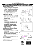
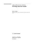
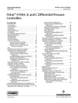
Electrode Size (S) : : : : : : : : : : : : : : : : : : : : : : : : : : : : : : : : : : : : : : : : : : : : : : : : : : : : : : : : : : : : : : : 38 60.5 (mm)
Dimension : : : : : : : : : : : : : : : : : : : : : : : : : : : : : : : : : : : : : : : : : : : : : : : : : : : : : : : : 85 (H) 285 (W) 237 (D) (mm)
Figure 1-1. Electrode Size of the 16452A (section view)
Weight : : : : : : : : : : : : : : : : : : : : : : : : : : : : : : : : : : : : : : : : : : : : : : : : : : : : : : : : : : : : : : : : : : : : : : : : : : : : : : : : : : : : : 1.4 kg
Maximum Operating Voltage : : : : : : : : : : : : : : : : : : : : : : : : : : : : : : : : : : : : : : : : : : : : : : : : : : : : : : : : : : 30 Vrms
1-2
General Information
Operating Frequency : : : : : : : : : : : : : : : : : : : : : : : : : : : : : : : : : : : : : : : : : : : : : : : : : : : : : : : : : 20 Hz to 30 MHz
The operating frequency diers according to the instrument that the 16452A is used with.
With the 4194A : : : : : : : : : : : : : : : : : : : : : : : : : : : : : : : : : : : : : : : : : : : : : : : : : : : : : : : : : : : : : 100 Hz to 15 MHz
With the 4284A : : : : : : : : : : : : : : : : : : : : : : : : : : : : : : : : : : : : : : : : : : : : : : : : : : : : : : : : : : : : : : : 20 Hz to 1 MHz
With the 4285A : : : : : : : : : : : : : : : : : : : : : : : : : : : : : : : : : : : : : : : : : : : : : : : : : : : : : : : : : : : : : 75 kHz to 30 MHz
Materials
Test xture body (electrodes, spacers, liquid inlet and outlet)
Nickel-plated cobal (Fe 54%, Co 17%, Ni 29%)
Insulator : : : : : : : : : : : : : : : : : : : : : : : : : : : : : : : : : : : : : : : : : : : : : : : : : : : : : : : : : : : : : Ceramic (alumina Al2 03)
O-ring : : : : : : : : : : : : : : : : : : : : : : : : : : : : : : : : : : : : : : : : : : : : : : : : : : : : : : : : : : : : : : : : : : : Viton (Fluoro rubber)
Insulator soldering : : : : : : : : : : : : : : : : : : : : : : : : : : : : : : : : : : : : : : : : : : : : : Silver-copper and gold-copper
The typical corrosive characteristics of these materials are shown in Appendix A.
Operating Temperature : : : : : : : : : : : : : : : : : : : : : : : : : : : : : : : : : : : : : : : : : : : : : : : : : : : : : : : : 020 to +125 C
The measurement cable's operating temperature is:
16048A : : : : : : : : : : : : : : : : : : : : : : : : : : : : : : : : : : : : : : : : : : : : : : : : : : : : : : : : : : : : : : : : : : : : : : : : : : : : 0 to +55 C
16452-61601 : : : : : : : : : : : : : : : : : : : : : : : : : : : : : : : : : : : : : : : : : : : : : : : : : : : : : : : : : : : : : : : : : : : 020 to +125 C
Non-Operating Temperature : : : : : : : : : : : : : : : : : : : : : : : : : : : : : : : : : : : : : : : : : : : : : : : : : : : : : : 040 to 70 C
General Information
1-3
Supplemental Performance Characteristics
This section lists supplemental performance characteristics. Supplemental performance
characteristics are not specications, but are typical characteristics included as additional
information for the operator. Supplemental performance characteristics are not guaranteed.
Electrode gap repeatability ( Screw torque: 15 kgf1cm)
Assembly repeatability : : : : : : : : : : : : : : : : : : : : : : : : : : : : : : : : : : : : : : : : : : : : : : : : : : : : : : : : : See Table 1-1.
Temperature repeatability (@ 23 C to 125 C) : : : : : : : : : : : : : : : : : : : : : : : : : : : : : : : : : : See Table 1-1.
Necessary liquid volume : : : : : : : : : : : : : : : : : : : : : : : : : : : : : : : : : : : : : : : : : : : : : : : : : : : : : : : : See Table 1-1.
Air Capacitance Value (@ 23 C 6 5 C, 1 MHz) : : : : : : : : : : : : : : : : : : : : : : : : : : : : : : : : See Table 1-1.
Table 1-1. Typical Data
Spacer thickness
Electrode gap
assembly repeatability
Electrode gap
temperature repeatability
Necessary liquid volume
Air capacitance value
1.3 mm
1.5 mm
2.0 mm
3.0 mm
0.3 mm612 m 0.5 mm612 m 1.0 mm612 m 2.0 mm612 m
0.3 mm62 m
0.5 mm62 m
1.0 mm62 m
2.0 mm62 m
3.4 cc
3.8 cc
4.8 cc
6.8 cc
10.9 pF 610%
5.5 pF 610%
34.9 pF 625% 21.2 pF 615%
Short residual (when using the furnished shorting plate with a 1.3 mm spacer)
Ls (equivalent series inductance) : : : : : : : : : : : : : : : : : : : : : : : : : : : : : : : : : : : : : : : : : : : : : : : : : : : : : : : 20 nH
Rs (equivalent series resistance) : : : : : : : : : : : : : : : : : : : : : : : : : : : : : : : : : : : : : : : : : : : : : : : : : : : : : : : : : 0.5 Temperature expansion coecient : : : : : : : : : : : : : : : : : : : : : : : : : : : : : : : : : : : : : : : : : : : : 6300ppm/ C
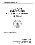
Additional impedance measurement error
In the following measurement,
The SHORT compensation is done.
The calculation is done using the capacitive measurement method (see \Capacitive
Measurement Method" in Chapter 3).
The measurement instrument is an 4194A, 4284A, or 4285A
The relative dielectric constant is 1 < j"_ r j < 500
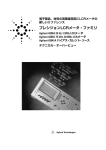
The xture error3 is dened by:
Error = A + B [%] (See Figure 1-4)
Where,
A
B
: Obtained from Figure 1-2.
: Obtained from Figure 1-3.
3 The measurement accuracy is a complex function of the measurement instrument accuracy and the xture error.
1-4
General Information
Figure 1-2. Fixture Error (A)
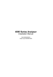
Figure 1-3. Fixture Error (B)
Figure 1-4. Fixture Error (A+B)
General Information
1-5
2
Initial Inspection
Introduction
The liquid test xture has been carefully inspected before being shipped from the factory. It
should be in perfect physical condition, no scratches, dents or the like. It should also be in
perfect electrical condition. Verify this by carefully performing an initial inspection to check
the liquid test xture set for signs of physical damage and missing contents. If any discrepancy
is found, notify the carrier and Agilent Technologies. Your Agilent Technologies sales oce will
arrange for repair or replacement without waiting for the claim to be settled.
Inspect the shipping container for damage. Keep the shipping materials until the inspection is
completed.
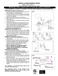
Verify that the shipping container contains everything shown in Figure 2-1 and listed in
Table 2-1.
Inspect the exterior of the 16452A for any signs of damage.
Initial Inspection
2-1
Product Overview
Figure 2-1. 16452A Product Overview
2-2
Initial Inspection
Reference
Designator
1
|
2
3
4
5
6
|
|
|
|
Table 2-1. Contents
Description
Liquid test xture
O-ring for electrodes1
Shorting plate
O-ring for liquid outlet
Spacer
1.3 mm (thickness) /0.3 mm (gap)2
1.5 mm (thickness) /0.5 mm (gap)
2.0 mm (thickness) / 1.0 mm (gap)
3.0 mm (thickness) / 2.0 mm (gap)
Lid of liquid outlet
SMA-BNC adapter
Waterproof cap for BNC connector3
Carrying Case
Operation and Service Manual4
Fixture stand5
Stand body
Screw for stand
Stand foot
Part Number
Quantity
16452A
0905-1275
16092-08010
0905-1277
1
2
1
1
16452-00601
16452-00602
16452-00603
16452-00604
16452-24002
1250-1200
1252-5831
16452-601014
16452-90000
1
1
1
1
1
4
4
1
1
|6
0515-0914
16452-00611
1
4
1
1 The O-rings are assembled in the 16452A.
2 The 1.3 mm spacer is assembled in the 16452A.
3 The cap is on the SMA-BNC adapter.
4 The carrying case and the
Operation and Service Manual are not shown in the Figure 2-1.
5 The xture stand is shown in Figure 2-2. Assemble it as shown in the gure.
6 The stand body is assembled using the two angle irons (16452-01201), and the four screws (0515-0914).
If you ordered a measurement cable (16048A, or 16452-61601), check that the cable is included.
Figure 2-2. Assembling the Fixture Stand
Initial Inspection
2-3
Repackaging the Test Fixture For Shipment
If shipment to a Agilent Technologies service center is required, each test xture should be
repackaged using the original factory packaging materials.
If this material is not available, comparable packaging materials may be used. Wrap the liquid
test xture in heavy paper and pack in anti-static plastic packing material. Use sucient shock
absorbing material on all sides of the 16452A to provide a thick, rm cushion and to prevent
movement. Seal the shipping container securely and mark it FRAGILE.
2-4
Initial Inspection
3
Operation
Introduction
This chapter describes how to measure the dielectric constant (") of the liquid using the
16452A.
The standard measurement sequence is shown in this chapter.
Some instructions for the temperature measurement are provided at the back of the chapter.
Measurement Sequence
Relative permittivity ("r ) can be calculated from the ratio of the capacitance of a material
to that of air (nearly equal to that of a vacuum). The standard measurement sequence is as
follows:
1. Prepare the test xture for use.
2. Connect the test xture.
3. Check the SHORT residual.
4. Set the instrument for capacitance measurement.
5. Do a SHORT compensation.
6. Do the air capacitance (C0 ) measurement.
7. Do the liquid capacitance and resistance (Cp, Rp) measurement.
8. Drain the liquid (after measurement).
9. Do the data processing|Calculate dielectric parameter from measurement data.
Measurement Requirements
To do the measurement, the following items are required:
16452A liquid test xture
Fixture stand (furnished with the 16452A)
SMA-BNC adapter (furnished with the 16452A)
Measurement cable (16048A or 16452-61601)
1.3 mm spacer for the SHORT compensation (furnished with the 16452A)
Shorting plate for the SHORT compensation (furnished with the 16452A)
A spacer (choose one of the furnished four spacers)
Measurement instrument ( 4194A, 4284A, or 4285A)
Liquid under test (enough for the spacer you are using)
In addition, the following items are useful:
For washing the 16452A, a brush, detergent, cloth, etc.
For high temperature measurements, gloves to prevent scalding.
Operation
3-1
Preparation of Test Fixture for Use
Before connecting the test xture, you must connect the SMA-BNC adapters to the 16452A
terminals. Also, the spacer and shorting plate must be set between the electrodes for the
SHORT compensation. The 16452A can be separated into High and Low electrodes to make
it possible to set the spacer and the shorting plate. The test xture's electrodes are easier to
clean if you separate the electrodes.
Connecting the SMA-BNC Adapters to the 16452A
Connect the SMA-BNC Adapters to the 16452A SMA-terminals as shown in Figure 3-1. The
waterproof caps for the BNC connector should be on when washing the electrodes.
Figure 3-1. Connecting the SMA-BNC Adapter
3-2
Operation
Separating the Test Fixture into High and Low Electrodes
Separate the test xture as shown in Figure 3-2.
Figure 3-2. Separating the Test Fixture into High and Low Electrodes
Cleaning and Drying the Electrodes
For the measurement, the 16452A electrodes must be clean. If the 16452A's electrodes are
smeared, wash and dry them thoroughly before assembling.
Caution
Do not use a detergent that corrodes the test xture. For a list of the materials
that are corrosive to the test xtures, see Appendix A.
Operation
3-3
Assembling the Test Fixture
Set the 1.3 mm spacer (electrode distance is 0.3mm) and the shorting plate as required. Then
assemble the 16452A as shown in Figure 3-3.
Figure 3-3. Assembling the Test Fixture for a SHORT Compensation
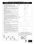
Putting the Lid On the Liquid Outlet
Put the lid on the liquid outlet as shown in Figure 3-4.
Figure 3-4. Putting the Lid On
3-4
Operation
Connecting the Test Fixture
Use a 4-terminal-pair BNC cable to connect the 16452A and your measurement instrument.
Agilent Technologies recommends using the following cables:
16048A Test leads
For the temperature range of 0 to +55 C
16452-61601 Test leads
For the temperature range of 020 to +125 C
Select the cable that matches your measurement.
Using the 4194A
1. Set the cable length.
When using the 16048A or 16452-61601 cable, set the cable length to 1 m, as follows:
Turn the 4194A OFF. Then set the Cable Length switch to 1 m (Figure 3-5). After setting the
switch, turn the 4194A ON.
Figure 3-5. Cable length switch (4194A)
2. Take the BNC adapter caps o and connect the test xture to the unknown terminal using
the cables (Lp: LPOT , Lc: CCUR , Hp: HPOT , Hc: HCUR ).
Figure 3-6. Connecting the Test Fixture (4194A)
Operation
3-5
Using the 4284A/4285A
1. Set the cable length.
When using the 16048A or 16452-616013 cable, set the cable length to 1 m, as follows:
a. Press 4MEAS SETUP5 CORRECTION .
NNNNNNNNNNNNNNNNNNNNNNNNNNNNNNNN
b. Place the cursor on CABLE : using 4 ( 5 4 ) 5 4 * 5 4 + 5.
c. Press 1m .
NNNNNNNN
When you use the test leads for the rst time, you must perform the cable correction. For
information on how to perform the correction, see the 4284A/4285A Operation Manual.
2. Take the BNC adapter caps o and connect the test xture to the unknown terminal using
the cables (Lp: LPOT , Lc: CCUR , Hp: HPOT , Hc: HCUR ).
Figure 3-7. Connecting the Test Fixture (4284A/4285A)
3 The 16452-61601 cable can be used in the same manner as the 16048A cable with 4284A/4285A.
3-6
Operation
Fixture Stand Usage
The xture stand sets the test xture stable and upright as required during the measurement.
Figure 3-8. Fixture Stand Usage
Operation
3-7
Checking the SHORT Residual
Before using the test xture, you should check its electrical performance. You can conrm its
performance by checking the SHORT residual. The SHORT residual must be measured with the
compensation function OFF because the compensation cancels the SHORT residual.
Using the 4194A
1. Set the compensation function OFF:
a. Press 4COMPEN5 OPEN OFS on/off . (When the softkey is dark, the compensation is OFF.)
NNNNNNNNNNNNNNNNNNNNNNNNNNNNNNNNNNNNNNNNNNNNNNN
b. Press 4COMPEN5 SHRT OFS on/off . (When the softkey is dark, the compensation is OFF.)
NNNNNNNNNNNNNNNNNNNNNNNNNNNNNNNNNNNNNNNNNNNNNNN
2. Select the measurement parameter \Ls-Rs":
a. Press 4FUNCTION5 IMPEDANCE Ls-Rs .
NNNNNNNNNNNNNNNNNNNNNNNNNNNNN NNNNNNNNNNNNNNNNN
3. Check the SHORT residual is the required value:
a. Press 4DISPLAY5 menu AUTO SCALE A .
NNNNNNNNNNNNNN NNNNNNNNNNNNNNNNNNNNNNNNNNNNNNNNNNNNNN
b. Press more 1/3 AUTO SCALE B .
NNNNNNNNNNNNNNNNNNNNNNNNNN NNNNNNNNNNNNNNNNNNNNNNNNNNNNNNNNNNNNNN
c. Press 4REPEAT5 until the light is ON.
d. Check that the Ls and Rs value at 1 MHz is in the following range:
Ls < 20 nH
Rs < 0.5 Using the 4284A/4285A
1. Set the compensation function OFF:
a. Press 4MEAS SETUP5 CORRECTION .
NNNNNNNNNNNNNNNNNNNNNNNNNNNNNNNN
b. Move the cursor to OPEN : and press OFF .
NNNNNNNNNNN
c. Move the cursor to SHORT: and press OFF .
NNNNNNNNNNN
d. Move the cursor to LOAD : and press OFF .
NNNNNNNNNNN
2. Select the measurement parameter \Ls-Rs":
a. Press 4DISPLAY FORMAT5.
b. Move the cursor to FUNC : and press more 1/6 more 2/6 more 3/6 Ls-Rs .
NNNNNNNNNNNNNNNNNNNNNNNNNN NNNNNNNNNNNNNNNNNNNNNNNNNN NNNNNNNNNNNNNNNNNNNNNNNNNN NNNNNNNNNNNNNNNNN
3. Check the SHORT residual value at 1 MHz is in the following range:
Ls < 20 nH
Rs < 0.5 3-8
Operation
If the SHORT Residual is Out of Range
1. Check the connection of the test xture and the measurement cable. Also, check the
shorting plate connection.
Is the spacer width in the 16452A 1.3 mm?
Does the shorting plate contact to both high and low electrodes?
Are the electrodes clean and free from rust?
2. If the problem cannot be corrected, please contact the nearest Agilent Technologies sales
oce.
Setting the Instrument for Capacitance Measurement
To measure the dielectric constant ("), the test xture uses a capacitance-measurement method.
This is done by measuring Cp (parallel equivalent capacitance) and Rp (parallel equivalent
resistance) and then calculating the dielectric constant (") and the dielectric loss (tan ).
Using the 4194A
1. Select the measurement parameter \Cp-Rp":
a. Press 4FUNCTION5 IMPEDANCE more 1/3 more 2/3 Cp-Rp .
NNNNNNNNNNNNNNNNNNNNNNNNNNNNN NNNNNNNNNNNNNNNNNNNNNNNNNN NNNNNNNNNNNNNNNNNNNNNNNNNN NNNNNNNNNNNNNNNNN
2. Select the other settings depending on each application.
Using the 4284A/4285A
1. Select the measurement parameter \Cp-Rp":
a. Place the cursor on FUNC using 4 ( 5 4 ) 5 4 * 5 4 + 5.
b. Press Cp-Rp .
NNNNNNNNNNNNNNNNN
2. Select the other settings depending on each application.
Operation
3-9
Performing a SHORT Compensation
Conrm that the 1.3 mm spacer and the shorting plate are set as specied in the \Preparation
of Test Fixture for Use".
Note
The OPEN and LOAD compensations are not required for the 16452A.
Using the 4194A
1. Press 4COMPEN5 ZERO SHORT
NNNNNNNNNNNNNNNNNNNNNNNNNNNNNNNN
4ENTER/EXECUTE5.
2. Press SHRT OFS ON .
NNNNNNNNNNNNNNNNNNNNNNNNNNNNNNNNNNN
Note
After the ZERO SHORT measurement, the 4194A goes to SINGLE SWEEP mode.
To select the REPEAT SWEEP mode, press 4REPEAT5 until the light turns on.
Using the 4284A/4285A
1. Press 4MEAS SETUP5 CORRECTION .
NNNNNNNNNNNNNNNNNNNNNNNNNNNNNNNN
2. Place the cursor on SHORT using 4 ( 5 4 ) 5 4 * 5 4 + 5.
3. Press MEAS SHORT .
NNNNNNNNNNNNNNNNNNNNNNNNNNNNNNNN
4. After the SHORT measurement is completed, press ON .
NNNNNNNN
3-10
Operation
Air Capacitance (C0) Measurement
1. Separate the test xture as shown in Figure 3-9.
Figure 3-9. Separating the Test Fixture into High and Low Electrodes
2. Remove the shorting plate and select the spacer that is to be used to measure the liquid.
Then assemble the test xture.
Figure 3-10. Test Fixture Assemble for Measurement
Operation
3-11
3. Measure the air capacitance value (C0 ) and record the measurement data. The data is used
to calculate the dielectric parameter.
Note
Compare the measured value with the value in the \Supplemental
Characteristics" in Chapter 1.
If the value is not correct, check the following:
Was the spacer correctly chosen and set?
Are the O-rings set correctly?
Are the high and low electrodes put tightly together?
Then perform the measurement procedure again
Liquid Capacitance and Resistance (Cp, Rp) Measurement
Warning
Be careful when dealing with liquids (especially volatile and/or ammable
liquid such as oil or organic solvents) that can cause an accident.
Accidents such as an explosion, ignition, emission of poison gas, scalding
(by heat or chemicals), and so on, are possible
To prevent any accidents, establish a strict process for the measurements.
(For example, using appropriate ventilation, a gas mask, and gloves.)
1. Pour the liquid under test into the 16452A until the liquid lls tube B . Pour the liquid
gently so that air does not get mixed in with the liquid.
Figure 3-11. Poring the Liquid under Test
3-12
Operation
Warning
Warning
When you pour the liquid, be careful that the liquid does not leak from
the test xture.
An 16452A assembled in the wrong manner (for example, lack of the
O-rings or the spacer) will cause liquid leakage. Assemble the 16452A
again if leakage is found.
If the problem cannot be corrected, please contact the nearest Agilent
Technologies sales oce.
DO NOT enclose the liquid in the 16452A. Carburetion of the liquid
enclosed in the 16452A can cause an explosion of the 16452A.
2. Measure the capacitance and equivalent parallel resistance value (Cp, Rp) of the liquid
under test and record the measurement data. The data is used to calculate the dielectric
parameter.
Warning
DO NOT apply a dc test signal to the 16452A. The dc signal can cause
electrolysis of the liquid.
When you use the 16452A in a thermostatic chamber or an oil tank, see the \Performing
Temperature Measurements" procedure.
Operation
3-13
Drain the Liquid (After Measurement)
1. Turn the lid of the liquid outlet and take it o. Drain the liquid (Figure 3-12).
Figure 3-12. Taking the Lid O
2. Wash and dry the test xture.
3-14
Operation
Data Processing|Calculate Dielectric Parameter from
Measurement Data
The dielectric parameter (") is calculated from the following equation.
Cp
1
)
"_ r = ( 0 j
Co
!CoRp
Where,
Correction coecient (see next page)
Relative dielectric constant (complex)
"_ r
Cp
Liquid capacitance (measurement data)
Co
Air capacitance (measurement data)
Rp
Equivalent parallel resistance (measurement data)
!
Angular frequency (! = 2f)
f
Frequency
(1)
Measurement Theory
The relative dielectric constant indicates the energy value of a material in an electric eld. It is
represented as a complex quantity. The relative dielectric constant ( "_ r ) is dened as the ratio
of the material's dielectric constant ( "_ ) to that of a vacuum ( "0 = 8:854 2 10012 ).
"_
"_ r =
"0
Also,
(2)
"_ r = "0 0 j"00
r
Loss tangent
r
"00
tan = r0
"r
Where,
"0r
"00r
Relative dielectric constant
Dielectric loss
The 16452A and Agilent impedance analyzer/LCR meter use the \Capacitive Method" for
obtaining relative permittivity by measuring the capacitance of a material that is sandwiched
between parallel electrodes.
Capacitive Measurement Method
The dielectric coecient ("0r ) and loss ("00r ) can be calculated from the capacitance and electrode
dimensions.
"00r =
(Where, the conductivity =
t
A2Rp ,
t 2 Cp
"0r =
A 2 "0
! 2 "0
=
t
! 2 Rp 2 "0 2 A
A is area of electrode, t is gap between electrodes. )
The dielectric constant of a vacuum ( "0 ) is calculated from the capacitance of the vacuum
(Approximately equal to air capacitance C0 ).
t 2 C0
"0 =
A
Therefore, the equation (2) can be rewritten in the same form as equation (1), when = 1.
Operation
3-15
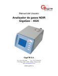
Correction Coecient
The measured data (Cp, Co) contains the stray capacitance, which alters by the dielecteric
constant.
Figure 3-13. Stray Capacitance
The stray capacitance can be cancelled by multiplying the correction coecient (), as shown
in equation (1). The value of is calculated by following equation.
100j"_ rm j
=
97:0442j"_ rm j + 2:9558
Figure 3-14. Correction Coecient
Where, "_ rm is the right side of equatrion (1), enclosed by ( ).
1
Cp
0
j
"_ rm =
!CoRp
Co
Therefore,
j"_ rm j =
3-16
Operation
r Cp
2
Co2
+
1
(!CoRp)2
Performing Temperature Measurements
The following information is provided for users who use the 16452A in a thermostatic chamber
or an oil tank.
The 16452A is specied to operate in the temperature range of 020 to 125 C. You should
be aware not only of the heat resisting property of the 16452A, but also that of the
measurement cable. The heat resisting properties of the Agilent Technologies-recommended
cables are:
0 to +55 C
16048A
020 to +125 C
16452-61601
When you use the thermocouple to monitor the inside temperature of the test xture, be
careful not to short the electrodes.
When you use the 16452A in an oil tank, soak the whole circle shown in Figure 3-15 (the
circle shows the size and position of the liquid space of the 16452A).
Warning
Figure 3-15. Soaking the 16452A in the Oil Tank
DO NOT touch the heated test xture, cable, and xture stand with your
naked hand. Use gloves to prevent scalding.
Operation
3-17
4
Service
Introduction
This chapter covers assembly replacement and troubleshooting information.
Warning
These servicing instructions are for use by qualied personnel only. Do
NOT perform any servicing (other than that contained in the operating
section) unless you are qualied to do so.
Assembly Replacement
Table 4-1, Table 4-2, and Table 4-3 list the replaceable parts for the 16452A. The parts listed
can be ordered from your nearest Agilent Technologies Oce. Ordering information must
include the Agilent part number and the quantity required.
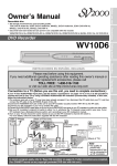
Service
4-1
Figure 4-1. 16452A Replaceable Parts (Major Parts)
Ref.
Desig.
1
2
3
4
5
6
7
8
Table 4-1. Replaceable Parts (Major Parts)
Agilent Part
Number
Qty.
Description
16452-60002
16452-24001
16452-00601
16452-00602
16452-00603
16452-00604
16092-08010
0905-1275
16452-24002
0905-1277
16452-60001
1250-1200
1
4
1
1
1
1
1
2
1
1
1
4
Low Electrode Assembly1
Screw
Spacer, 1.3 mm (thickness) / 0.3 mm (gap)
Spacer, 1.5 mm (thickness) / 0.5 mm (gap)
Spacer, 2.0 mm (thickness) / 1.0 mm (gap)
Spacer, 3.0 mm (thickness) / 2.0 mm (gap)
Shorting Plate
O Ring
Lid of Liquid Outlet
O Ring for Lid
High Electrode Assembly1
SMA(m)-BNC(f) Adapter
1 Assembling procedure of the electrode is described later in this chapter.
4-2
Service
Agilent Part
Number
16452-04001
0905-1276
0515-0994
1252-5831
16452-01201
16452-00611
0515-0914
16452-60101
16452-90000
Table 4-2. Replaceable Parts (Other parts)
Qty.
2
2
8
4
2
1
8
1
1
Description
Round Cover for Back of the Electrode
O Ring for the Cover
Screw for the Cover
Waterproof Cap for BNC Connector
Angle Iron for the Stand
Plate for the Stand Foot
M3 Screw for the Stand
Carrying Case
Operation and Service Manual
Service
4-3
Electrode Assembly
Figure 4-2. 16452A Replaceable Parts (Around SMA Connector)
Ref.
Desig.
1
2
3
4
5
6
4-4
Service
Table 4-3. 16452A Replaceable Parts (Around SMA Connector)
Agilent Part
Number
Qty.
Description
16452-61603
16452-61602
16452-25001
16452-29001
16452-25002
2190-0654
0515-0976
2
2
4
4
8
8
8
SMA Cable Assembly for High Electrode
SMA Cable Assembly for Low Electrode
Insulator
O Ring
Insulator
Washer, M2
Screw, M2
Figure 4-3. Inside of the Electrode Assembly
Assembling Procedure for Electrode
See Figure 4-2 and Table 4-3 for the reference designators.
1. Pass the SMA cable assembly 1 through the insulator 2 and the O ring 3.
2. Insert the cable into the electrode body, and connect it using the insulators 4 , the washers
5 and the screws 6 .
3. Bend the semi-rigid cable at 33 mm from the top face of the electrode body as described in
Figure 4-3, and set the angle between the semi-rigid cables close to 90 .
4. Solder the semi-rigid cables to the center pin of the electrode.
5. Solder the shield of the cable to the copper round plate using solder wick.
Service
4-5
Troubleshooting
When the short residual resistance is out of the limit, check the xture connection, the
shorting plate, and the surface of the electrodes. If the surface of the electrode is damaged,
electrode assembly replacement is required for restoring proper electrical performance.
When the short residual inductance is out of the limit, check the angle of the semi-rigid cables
in back of the electrode assemblies. The angle should be close to 90 . Also check the shield of
the semi-rigid cables are connected only at the copper round plate.
Caution
4-6
Service
Do not polish the surface with powder to protect the electrode.
A
Liquids that Corrode the Test Fixture
The appendix A provides information about the liquids that corrode the test fixture.
The liquid under test directly contacts the following materials:
Nickel – the test fixture body (electrodes, spacers, liquid inlet and outlet).
Ceramic (alumina Al2O3) – the insulator around the electrodes.
Rubber (Fluoro rubber) – the O-rings.
Silver copper and gold-copper – the insulator soldering.
Do not use the test fixture with liquids that corrode these materials. Typical corrosive liquids for each
material are listed in the following sections.
Do not apply DC test signal (or low-frequency test signal) to electrolyte
solutions (ionic solutions) such as salt. The DC signal (or low-frequency
signal) can cause electrolysis reaction of the liquid.
Nickel Corrosive Liquid
Corrosive liquid
acid oxidant and salt oxidant
For example,
nitric acid (HNO3)
nitrous acid (HNO2)
ferric chloride (FeCl3)
cupric chloride (CuCl2)
mercuric chloride (HgCl2)
Little-corrosive liquid
hydrochloric acid (HCl)
sulfuric acid (H2SO4)
organic acid
Non-corrosive liquid
alkali salt
acetic acid (CH3CO2H)1
formic acid (HCO2H)1
citric acid (HO2CC(OH)(CO2H)2.H2O)1
1 In the case of high temperature and air-mixed.
Liquids that Corrode the Test Fixture
A-1
Ceramic (alumina : Al2O3) Corrosive Liquid
Aqueous solution of fluoride corrodes the ceramic.
Viton (Fluoro rubber) Corrosive Liquid
Ketone and ester corrode the Viton.
Silver-copper and gold-copper
Strong acid liquid corrodes silver copper and gold copper.
A-2
Liquids that Corrode the Test Fixture