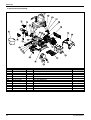
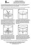
1
SERVICE MANUAL
FORTRESS-CALYPSO
3- & 4- WHEEL SCOOTER
© 2011 Handicare
All rights reserved.
The information contained in this manual may not be reproduced and/or published in any form, by print, photoprint, microfilm or by any other
means, whether electronically or mechanically, without the prior written authorisation of Handicare.
The information provided is based on the general data relating to the design of the product known at the time of publication of this manual.
Handicare has a policy of continuous improvement and reserves the right to make changes and modifications to its products.
The information provided applies to the standard version of the product. Handicare can not be held liable for any damage resulting from product
specifications which do not conform to the standard configuration.
The information made available has been compiled with the greatest care. However, Handicare can not be held liable for any possible errors in
the information or for the consequences thereof.
Handicare accepts no liability for loss as a result of work carried out by third parties.
Under regulations concerning the protection of trade names, the names and trade names etc. used by Handicare may not be regarded as
openly available.
2
Version 2015v1
Table of contents
This manual ................................................................................................................................................................. 4
Available documentation ........................................................................................................................................... 4
Productlabels .............................................................................................................................................................. 4
Symbols used in this manual: ................................................................................................................................... 5
Service and technical support................................................................................................................................... 6
Identification plate ...................................................................................................................................................... 6
Identifying the product ............................................................................................................................................... 6
Approvals .................................................................................................................................................................... 6
CE declaration ............................................................................................................................................................. 6
Used scooters and the environment ........................................................................................................................ 6
Warranty ...................................................................................................................................................................... 7
(1)
Use for intended purposes .................................................................................................................................... 8
1 General safety rules and regulations ................................................................................................................ 9
1.1 Labels and instructions on the scooter ........................................................................................................... 9
1.2 Technical specifications ................................................................................................................................. 9
1.3 Adaptations..................................................................................................................................................... 9
1.4 Safety ............................................................................................................................................................. 9
2 Adjustment options ........................................................................................................................................... 11
2.1 Adjusting the seat ......................................................................................................................................... 11
2.1.1
Adjusting the seat height ....................................................................................................................... 11
2.1.2
Adjusting the seat depth (sliding system) ............................................................................................ 11
2.1.3
Adjusting the backrest ........................................................................................................................... 11
2.1.4
Adjusting the armrest ........................................................................................................................... 12
2.1.5
Adjusting the headrest .......................................................................................................................... 12
2.2 Adjusting the steering column ...................................................................................................................... 12
2.3 Adjusting the rear suspension ...................................................................................................................... 12
3 Programmer ....................................................................................................................................................... 13
4 Electrical diagram .............................................................................................................................................. 15
5 Technical specifications ................................................................................................................................... 16
5.1 Fortress Calypso product specifications ...................................................................................................... 16
6 Service instructions .......................................................................................................................................... 18
6.1 Maintenance diagram ................................................................................................................................... 18
6.2 Maintenance instructions .............................................................................................................................. 18
6.3 Instructions for repair .................................................................................................................................... 18
7 Use of the parts list ........................................................................................................................................... 19
8 Parts list .............................................................................................................................................................. 20
A: Overview 3W ................................................................................................................................................... 21
B: Overview 4W ................................................................................................................................................... 23
001: Wheel front assy .......................................................................................................................................... 25
002: Wheel rear assy ........................................................................................................................................... 26
003: Bumper rear assy ........................................................................................................................................ 27
004: Top console assy ......................................................................................................................................... 28
005: Bottom console assy ................................................................................................................................... 29
006: Tiller assy..................................................................................................................................................... 30
007: Tiller strut assy ............................................................................................................................................ 31
008: Cover battery assy ....................................................................................................................................... 32
009: Cover motor assy ........................................................................................................................................ 33
010: Frame front 3W assy ................................................................................................................................... 34
011: Front fork assy ............................................................................................................................................. 35
012: Cover front 3W assy .................................................................................................................................... 36
013: Frame front 4W assy ................................................................................................................................... 37
014: Swing arm right assy ................................................................................................................................... 38
015: Swing arm left assy ..................................................................................................................................... 39
016: Cover front 4W assy .................................................................................................................................... 40
017: Rear frame top assy .................................................................................................................................... 41
018: Rear frame assy .......................................................................................................................................... 42
019: Rear frame bottom assy .............................................................................................................................. 43
020: Transaxle assy ............................................................................................................................................ 44
021: Captain seat assy ........................................................................................................................................ 45
022: Armrest adjustable assy .............................................................................................................................. 46
Version 2015v1
3
Introduction
This manual
This manual contains the basic instructions for repairs and general maintenance of the Calypso electric scooter.
Mechanics who do repairs on this scooter must be well trained and familiar with the repair methods and the
maintenance of the Calypso electric scooter.
It is important to see to it that work is always done safely, particularly with respect to activities where the scooter
must be lifted up.
We advise that you contact our service department before doing repair work on a scooter that has been involved in
an accident.
The following specifications are important when ordering parts:
• Model
• Manufacture year
• Identification number
• Part number
• Name of the relevant part
This information can be found on the identification plate. See 'Identification of the product'.
Available documentation
The following technical documentation is available / required to service this scooter:
•
•
User manual
Service manual
Productlabels
The following stickers and labels can be found on the product:
A. Charging point
B. Circuit breaker
C. Tyre pressure
D. Neutral position
E. Adjustment of steering column angle
4
Version 2015v1
Introduction
A. Charging point
See the chapter on ‘Charging the batteries’, section 5.1, for how to charge the batteries.
B. Circuit breaker
The scooter is equipped with a fuse which interrupts the electric current on overload. See
‘Automatic circuit breaker’, section 7.2.
C. Tyre pressure
See the ‘product specifications’ for the correct tyre pressure.
D. Neutral position – Free wheel facility
1. Lever fully forward (“BRAKE applied”):
When the motor drive is engaged the scooter can be driven electrically and the brakes
are also applied when the scooter is switched off.
1. When the lever is in the lowest position
the motor drive is disengaged. The scooter can then be pushed manually.
E. Adjusting the steering column angle
The steering column can be adjusted to the position you find most comfortable when
driving. See ‘Changing the position of the steering column’, section 4.1.6.
Symbols used in this manual:
CAUTION
Operations or manoeuvres which are not carried out correctly may result in damage to the product or
the environment, or in user injury.
ATTENTION!
Suggestions for making specific operations or manoeuvres easier to carry out.
First consult the source(s) of information given.
Disconnect the charging cable from the charging point on the scooter before carrying out any
maintenance on the scooter.
Version 2015v1
5
Introduction
Service and technical support
Your dealer should be contacted for information about specific adjustments, maintenance or repair and will be
happy to help you.
When contacting your dealer, please ensure you have the following information to hand:
• Model
• Serial number
This information can be found on the information plate. See the illustration below.
Identification plate
Product information is recorded on plate (A). See: ‘Identifying the product’.
A
Identifying the product
A.
B.
C.
D.
E.
Model
Date of manufacture
Serial number / identification number
Usage: Indoor use, outdoor use or both
Maximum load in kg
Approvals
The product meets the following requirements:
• EN12184; 1999 Electrically powered wheelchairs and scooters, class B.
• EN12182; 1999 Technical aids for disabled persons.
• ISO7176-8 Requirements for static, impact and fatigue strengths.
• ISO7176-9 Climatic tests for electric wheelchairs and scooters.
• ISO7176-14 Requirements and test methods for power and control systems for electric wheelchairs.
• ISO7176-16 Requirements for resistance to ignition of upholstered parts.
The product has been EMC-approved (for electromagnetic compatibility) in accordance with EN12184 (1999).
CE declaration
The product complies with the regulations of the Medical Devices Directive and therefore bears the CE mark.
Used scooters and the environment
If your scooter is no longer required or needs to be replaced, it will usually be possible to arrange
for your dealer to take it back. If this should not be possible, consult with your local authority to
find out if the scooter can be recycled or if the materials used in it can be processed in an
environmentally friendly way.
Various plastics and metals were used in the manufacture of the scooter. The scooter also
contains electronic components which should be disposed of accordingly. The batteries constitute
chemical waste.
6
Version 2015v1
Introduction
Warranty
Definitions of terms used in this warranty:
• Consumable part: Part that is subjected to natural wear and tear or natural contamination during normal operation
within the lifetime of the product (section 9 of Handicare’s general terms and conditions of sale);
• Client: Those who purchase the product directly from Handicare;
• Corrective action: Repair, replace or refund of the product;
• Dealer: Those who re-sell the product to the User;
• Defect: Any circumstance due to which the product is not sound or fit to use, caused by a lack of quality of the
material used to manufacture the product as well as the quality of the manufacturing process;
• Option: An accessory delivered by Handicare to extend the standard product model;
• Product: Product that is delivered according to brochure or contract (e.g. wheelchair, scooter, battery-charger etc.);
• Part: Part of product that can be exchanged or replaced. This can be an option, accessory, service part or
consumable part;
• Returns: Product or part that needs to be returned;
• RMA-process: Process to return goods, contact Handicare’s Customer Service;
• Service part: Part that is durable and may be subjected to natural wear and tear or natural contamination during
normal operation within the lifetime of the product.;
• User: Those who use the product;
• Warranty: The rights and obligations set forth in this document;
• Warranty period: The period of time during which the warranty is valid;
• Warranty provider: Handicare B.V., Vossenbeemd 104, 5705 CL Helmond, The Netherlands.
Notwithstanding the rights and obligations of Handicare, Client and User set forth in Handicare’s general terms and
conditions of sale, the rights of the Client and/or User towards Handicare in case of defects are limited to the
provisions set forth in this warranty. For the duration of the warranty period Handicare guarantees that the product
is without defects.
In case of any defects the User is required –within two weeks after discovery of the defect- to contact the dealer.
He has to complete a return form and return the product or part via the RMA-process. Handicare will, at its sole
discretion, take the corrective action it seems fit under the given circumstances within a reasonable period of time
(depends on nature of claim) from receipt of the completed return form. The warranty period will not be extended
after a corrective action.
Warranty period table
Power wheelchairs / scooters
Description
Warranty period
Examples include, but are not limited to
the parts mentioned below
Frame
2 years
Weldment/frame
Drive system
1 year
Transaxle, motor, motor brake
Electronics
1 year
Controller, controlling mechanism, wiring
harness, electronic components
Service Parts
New: 1 year after invoice
Repaired: 90 days after invoice
Brakes
Consumable parts
40 days after invoice
Wheels, push handles etc.
Options/Accessories
2 years
Mirror, mudguards etc.
Not being service part or consumable part.
Handicare will only accept shipment costs and corrective costs related to warranty on equipment during the
warranty period.
This warranty will void in case of:
• The product and/or its parts being modified or items having been added by others than Handicare;
• Changes in cosmetic appearance by use;
• Failure to observe the instructions for use and maintenance, use other than normal use, wear and tear,
negligence, collateral damage by neglect of earlier symptoms, overloading, third-party accidents, non-original parts
used and defects not caused by the product;
• Circumstances beyond our control (flood, fire, etc.).
Version 2015v1
7
Introduction
This warranty does not cover:
• Tyres and inner tubes
• Batteries (covered by the battery manufacturer’s warranty).
Clients and/or Users have legal (statutory) rights under applicable national laws relating to the sale of consumer
products. This warranty does not affect statutory rights you may have nor those rights that cannot be excluded or
limited, nor rights against the entity from whom the product was purchased. Clients may assert any rights they have
at their sole discretion..
Use for intended purposes
(1)
The Fortress Calypso scooter was developed for:
•
The transportation of people weighing up to 125 kg
•
Use on pavements, footpaths and cycle paths
•
Use in and around the house
The dealer must give you clear instructions before you start operating the product independently.
Your first test drives of the Fortress Calypso are best carried out under the supervision of an experienced dealer.
The Fortress Calypso scooter is not classified as a road vehicle and therefore may not be used on the road
(crossing over the road being the only exception).
The Fortress Calypso has a maximum speed of 10 km/h (6 mph).
ENSURE THAT YOU ARE FULLY ACQUAINTED WITH THE CONTENTS OF THIS MANUAL BEFORE
STARTING TO DRIVE THE FORTRESS CALYPSO.
If you use the scooter in a dangerous fashion, or use the scooter for purposes other than those intended,
Handicare will accept no liability for any personal injury or damage to property caused by such misuse.
(1)
Intended use, as specified by EN 292-1, means the use for which the technical product is suitable according to the manufacturer’s
declaration, including the manufacturer’s instructions in the sales brochure. In the event of doubt, use is taken to mean the use as construed
from the design, construction and function of a product. The instructions contained in the user manual must also be followed within the scope of
intended use.
8
Version 2015v1
General safety rules and regulations
1 General safety rules and regulations
Handicare accepts no liability for loss or injury caused by not following the safety rules and regulations fully, or
otherwise for loss or injury as a result of negligence during use or when cleaning the scooter and any accessories.
Supplementary safety regulations may apply depending on the specific circumstances for operation or on the
accessories used. Please contact your dealer immediately if you should ascertain any potential hazards when
using the product.
The user of the scooter (see ‘Intended use’) is at all times responsible for following local safety
rules and guidelines.
1.1
Labels and instructions on the scooter
The markings, symbols and instructions on the scooter constitute a part of the safety guidelines for the scooter. For
this reason they may never be covered or removed and must be present and clearly legible for the entire period of
time the scooter is in existence.
Illegible or damaged labels, symbols and instructions must be replaced or repaired immediately. Contact your
dealer in such cases.
1.2
Technical specifications
No changes may be made to the technical specifications.
1.3
Adaptations
Adaptations to components of this product are not permitted.
1.4
Safety
It is of great importance that attention be paid to the following safety regulations for the prevention of accidents and
undesirable situations.
Take extra care when driving on slopes:
• Never remove safety devices, such as the anti-tip wheels.
• Never drive the Fortress Calypso up slopes with a gradient greater than that specified in
section 5.4.3 of this manual.
• Always drive up slopes slowly and take extra care.
• Never descend a slope at full speed.
• Do not drive down slopes covered with loose gravel or with a sandy surface, as one of the back
wheels may slip.
• Do not turn on slopes.
• Never take corners at full speed. Reduce speed before taking a corner.
• When driving up a slope, adopt a position which promotes stability, as described in section
5.4.3 of this manual.
• Ensure that clothing does not trail as this can become entangled in the wheels.
• Ensure that your fingers do not become trapped in the mechanism for adjusting the position of
the steering column.
You must adjust your driving to the prevailing conditions:
Drive carefully on roads which have become slippery due to rain, black ice or snow!
Reduce speed in busy surroundings.
Do not use the scooter on unsurfaced roads.
Ensure that the Fortress Calypso A does not come into contact with salt water. Salt water is
corrosive and can damage the scooter.
• Ensure that the Fortress Calypso does not come into contact with sand. Sand can find its way
into the moving parts of the scooter, resulting in these parts wearing out unnecessarily
quickly.
• Never drive the scooter while under the influence of drugs, alcohol or prescription medications
which could affect your driving ability.
• Your eyesight must be adequate for you to drive the scooter safely.
•
•
•
•
Version 2015v1
9
General safety rules and regulations
• If visibility is not ideal, then it is obligatory for the lights to be turned on. The scooter is
equipped with brake lights which illuminate on braking.
• Use the indicator lights only to indicate a change in driving direction.
• Only use the horn for warning pedestrians or other road users of possibly hazardous
situations.
• Never place metal components on top of the batteries. Doing so could cause a short circuit,
leading to damage.
• Do not transport any passengers on the scooter. The scooter has been specifically designed to
transport you alone.
• Do not drive the scooter with the seat backrest angled too far to the rear. This can affect weight
distribution and the stability to the rear of the scooter, in particular when driving up slopes or
over obstacles.
• Ensure that your scooter does not transport a greater load than fits in the basket. Never hang
anything on the tiller.
• Never use the scooter for pulling a trailer. The scooter has not been designed for such use and
doing so can cause serious damage to your scooter.
• Do not stand on the platform in order to reach up to objects.
• Do not position your feet too close to the front wheel and fork when driving. Always keep your
feet on the rubber mat and not up against the front tiller cover.
The scooter is electronically driven. Specific parameters have been factory-set. These settings
have been made in order to ensure that use of the Fortress Calypso is comfortable and efficient
and they can not be changed.
The standard version of your scooter has been tested in accordance with the most stringent
requirements for electromagnetic interference.
If you use a mobile telephone near to a specially adapted scooter, it is advisable to switch the
scooter off first.
Your scooter can affect electromagnetic fields, such as alarm systems. If the scooter’s electronics
are not well shielded, sensitive electrical devices, such as shop alarm systems and garage door
openers, can be affected. The scooter has been tested for such interference. Please report any
problems of this nature to your dealer immediately.
• Beware of ultraviolet light. Ultraviolet light can cause premature wear of materials such as
rubber, plastic and enamel.
• Pay attention to objects sticking out from the scooter. These can cause damage to your
surroundings or to the scooter itself.
• Keep the scooter away from open flames.
• Avoid extreme weather conditions or extremely wet conditions. Maintain and store the scooter
in a clean and dry state.
10
Version 2015v1
Adjustment options
2 Adjustment options
There are a number of adjustments which can be made to the Fortress Calypso in order to improve its seating and
driving comfort levels.
Some adjustments are permanent adjustments made by the dealer using tools.
Other adjustments can be made by the user without the use of tools.
Adjustments can be made to the following by your dealer:
• Seat height
• Rear suspension
Adjustments can be made to the following by the user:
• Seat depth
• Backrest angle
• Armrest width
• Armrest height
• Headrest
• Steering column
2.1
2.1.1
Adjusting the seat
Adjusting the seat height
The entire seat can be adjusted in height in order to obtain the optimal seating position. This adjustment is carried
out by the dealer.
2.1.2
Adjusting the seat depth (sliding system)
(seat may vary from the illustration)
The seat depth can be adjusted as follows:
• Lift and hold handle (A).
• Slide the seat forwards or backwards.
• Release the handle once the seat is in the required position. Now slide the seat
slightly forwards or backwards so that it locks into place.
• The seat depth has now been adjusted.
2.1.3
Adjusting the backrest
A
The backrest angle can be adjusted as follows:
Lift handle (A) whilst sitting on the seat.
The backrest now automatically moves forwards.
• Push the backrest to the rear by leaning against it until it is in the position
you find the most comfortable.
• Once adjusted, release the handle. The backrest remains in the position
you selected.
•
Caution: Exercise caution when using the handle when no
one is sitting on the seat. The backrest is equipped with a
spring mechanism which causes it to be driven quickly
forwards with some force.
A
The backrest can be adjusted to provide good back support while driving.
If the backrest is adjusted to an angle too far to the rear, the driver’s seating position is then less
stable, particularly on slopes.
It is therefore important never to drive your scooter if the backrest is inclined too far back.
Version 2015v1
11
Adjustment options
2.1.4
Adjusting the armrest
The armrests can be adjusted as follows:
• Rotary knobs (A) for adjusting the distance between the armrests are located at the
back of the seat.
• Turn the knob in an anti-clockwise direction to loosen the armrest.
• Once you have adjusted the distance between the armrests, tighten the rotary knobs
by turning in a clockwise direction. Then check to see whether the armrests are firmly
in place.
• The rotary knobs (B) for adjusting the height of the armrests are located on the rods
B
supporting the armrests.
• Turn the knob in an anti-clockwise direction to loosen the armrest.
A
• Press the nipple and slide the armrest upwards or downwards into one of the three
positions.
• Once you have adjusted the height, tighten the rotary knobs by turning in a clockwise direction. Then check to see
whether the armrests are firmly in place.
2.1.5
Adjusting the headrest
The headrest can be adjusted to various heights.
The headrest height is adjusted as follows:
• Press the plastic button at the point where the headrest is attached to the seat, at the same time moving the
headrest to the required height. The headrest can also be removed if required.
• Release the button and move the headrest slightly so that it locks into one of the positions.
2.2
Adjusting the steering column
The steering column can be adjusted to make driving more comfortable
and to make it easier for you to mount and dismount from the scooter.
The steering column is adjusted as follows:
• Using one hand, pull handle (A) downwards while pulling the steering
column towards you with the other hand until it is in the most comfortable
position.
• Release the handle. Then release the steering column.
If you release the steering column while still pulling the handle down, the
pneumatic spring will cause the steering column to jump into the most
forward position automatically.
A
Exercise caution while adjusting the steering column and
ensure that your fingers do not become trapped.
2.3
Adjusting the rear suspension
The rear suspension of the scooter can be adjusted to provide optimal comfort. This adjustment is carried out by
the dealer.
12
Version 2015v1
Programmer
3 Programmer
The Fortress Calypso can be programmed with both the DX-HHP Hand-Held-Programmer and the Wizard. In both
cases, use the orange DWIZ adaptor and connect to the charger socket of the scooter.
For the standard settings of the programmer, see the R series DR-50 and DR-90 installation manual that can be
downloaded on www.dynamiccontrols.com.
The driving programs for Handicare products can be found on our FTP server.
Log on to the FTP server:
• Open internet explorer
• Go to ftp://mobilityftp.handicare.com
• Enter user name and password
User name: [email protected]
Password: dealer
• You will be logged on
• Select your wheelchair and the appropriate controller
• Click the file to download
If you wish to order parts for your programmer, please contact Handicare.
DWIZ-ADAPT 1009567
The specific and optimised Fortress Calypso settings are summarized in the table below.
User Personalisation
Swap Throttle Direction
Enable Beeper
Flash Code Beeper
Sleep Beeper
Reversing Beeper*
Beeper On Time (ms)
Beeper Off Time (ms)
10km/h or 6mph
No
Yes
No
Yes
Yes
300
700
8km/h or 5mph
No
Yes
No
Yes
Yes
300
700
*These settings have no influence, are set via dip-switches on Tiller PCB (see Chapter 6.3)
Version 2015v1
13
Programmer
Throttle Configuration
Throttle Type
Throttle Input
Throttle Neutral Offset (V)
Throttle Full Scale Deflectio
Throttle Response (%)
Throttle Dead-band (%)
10km/h or 6mph
Wig-wag
Single
0.00
70
60
25
8km/h or 5mph
Wig-wag
Single
0.00
70
60
25
Motor Management
Motor Reverse
Load Compensation (mOhm)
Current Limit (A)
Boost Current (A)
Boost Time (s)
10km/h or 6mph
No
80
50
8
8.0
8km/h or 5mph
No
80
50
8
8.0
Transaxle power
450 watt for 2 hrs
Load of ±20A at 24V
Park Brake Management
Park Brake Neutral Delay (ms)
Park Brake Release Delay (ms)
10km/h or 6mph
500.0
0.0
8km/h or 5mph
500.0
0.0
Battery Management
Battery Resistance (mOhm)
Fuel Gauge High Warning (V)
Fuel Gauge Low Warning (V)
10km/h or 6mph
15
29.0
23.4
8km/h or 5mph
15
29.0
23.4
System Options
Service Scheduler
Service Period (hours)
10km/h or 6mph
No
5000
8km/h or 5mph
No
5000
Input Pin
Pin 4 Function
Pin 6 Function
Pin 12 Function
Pin 14 Function
Prog/Inh Pin Function
Function
None
None
None
None
Charger Inhi
Multi-function Outputs Configuration
Flash Code Type
Pin 3 Function
Pin 10 Function
Pin 11 Function
14
Active
Low
Low
Low
Low
Low
Slows to
100
100
100
100
100
Latches
No
No
No
No
No
Scooter
Beeper
Status High
Status
Version 2015v1
Electrical diagram
4 Electrical diagram
Version 2015v1
15
Technical specifications
5 Technical specifications
Handicare B.V.:
5.1
Vossenbeemd 104
5705 CL, Helmond
The Netherlands
Fortress Calypso product specifications
Model
Maximum user weight
Fortress Calypso 3 wheels (3W)
Fortress Calypso 4 wheels (4W)
125 kg
Description
Total length
Total width
Minimum height*
Total weight excluding batteries:
Total weight including batteries:
Weight of heaviest component
Static stability in the downward direction
Static stability in the upward direction
Lateral static stability
Distance range (ISO 7176-4)**
Dynamic stability (max. safe slope)
Maximum speed forwards
Back angle, Captain Seat
Seat depth, Captain Seat
Seat width, Captain Seat
Back height (excl. headrest), Captain Seat
Seat height (to platform), Captain Seat
mm (inches)
mm (inches)
mm (inches)
kg (pounds)
kg (pounds)
kg (pounds)
°
°
°
km (miles)
°
km/h (mph)
°
mm (inches)
mm (inches)
mm (inches)
mm (inches)
Armrest height, Captain Seat
mm (inches)
Distance between armrests, Captain Seat
mm (inches)
Back angle, Master Seat
Seat depth, Master Seat
Seat width, Master Seat
Back height (excl. headrest), Master Seat
Seat height (to platform), Master Seat
°
mm (inches)
mm (inches)
mm (inches)
mm (inches)
Armrest height, Master Seat
mm (inches)
Distance between armrests, Master Seat
mm (inches)
3W
1207 (47.5)
622 (24.5)
710 (28)
70 (154.3)
100 (220.5)
27 (59.5)
15 (27%)
15 (27%)
15 (27%)
40 (24.9)
9 (16%)
10 (6)
0-103-126
445 (17.5)
457 (18)
406 (16)
432-490
(17-19.3)
229-273
(9-10.8)
457-610
(18-24)
85-180
430 (16.9)
500 (19.7)
550 (21.7)
432-510
(17-20.1)
150-340
(5.9-13.4)
500 (19.7)
4W
1214 (47.8)
622 (24.5)
710 (28)
75 (165.3)
105 (231.5)
32 (70.5)
15 (27%)
15 (27%)
15 (27%)
40 (24.9)
9 (16%)
10 (6)
0-103-126
445 (17.5)
457 (18)
406 (16)
432-490
(17-19.3)
229-273
(9-10.8)
457-610
(18-24)
85-180
430 (16.9)
500 (19.7)
550 (21.7)
432-510 (1720.1)
150-340
(5.9-13.4)
500 (19.7)
Description
Turning radius (ISO 7176-5)
Obstacle height (max. user weight)
Ground clearance (max. user weight)
mm (inches)
mm (inches)
mm (inches)
3W
1170 (46.1)
76 (3)
101 (4)
4W
1600 (63)
76 (3)
101 (4)
Test data
Test weight
125 kg
Operating force
Drive lever operation
Resetting the automatic fuse (circuit breaker)
Electronic switches
Connecting the charger plug
< 60 N
< 60 N
< 15 N
< 60 N
16
Version 2015v1
Technical specifications
Technical specifications for wheels
Front wheel diameter (3W)
Front wheel diameter (4W)
Rear wheel diameter
Tyre pressure 4W, front wheel
Tyre pressure 4W, rear wheel
Tyre pressure 3W, front wheel
Tyre pressure 3W, rear wheel
Batteries
Maximum dimensions of batteries (lxbxh)
Max. battery capacity
Maximum permitted charging current
*
**
mm (inches)
mm (inches)
mm (inches)
bar (psi)
bar (psi)
bar (psi)
bar (psi)
mm
(inches)
Ah
Ampère
260 x 85 (10.2 x 3.3)
260 x 85 (10.2 x 3.3)
260 x 85 (10.2 x 3.3)
3.5 (50)
3.5 (50)
3.5 (50)
3.5 (50)
3W
197x168x175
(7.8x6.6x6.9)
60 (C20)
8
4W
197x168x175
(7.8x6.6x6.9)
60 (C20)
8
height of steering column, collapsed, excluding seat
range dependent on user weight, condition of tyres, type of terrain, condition of battery and weather conditions.
Version 2015v1
17
Service instructions
6 Service instructions
6.1
Maintenance diagram
Every year or every 1000 km the following parts must be checked or replaced:
• Battery
• Lights
• Fuses
• Tyres
• Transaxle
• Carbon brushes
6.2
Maintenance instructions
Check condition of the battery/leakage
Check lights
Check fuses
Check tyres (wear and tension)
Check Transaxle (free wheel lever, leakage etc.)
Replace carbon brushes
Lubrication (seat post and slider)
•
•
•
•
•
•
•
6.3
Instructions for repair
Make sure that the scooter is disconnected from the batteries before executing any repair work.
When replacing the transaxle, always reset the current free wheel lever.
(De-)activating of audible signal for indicator, alarm and reverse-beep.
These dip-switches are located at the botom-side of the Tiller PCB (004-2). First remove the shroud front assy
(005-4) and the shroud rear assy (005-5) by unscrewing the 4x cross-head screws. Now you’ve acces to the 4
cross-head screws of the top console assy (004).
ON
No signal
1 2
ON
Only indicators and alarm signal (when contact is switched on)
1 2
ON
Only reverse beep
1 2
ON
All audible signals are activated (when contact is switched on)
1 2
18
Version 2015v1
Use of the parts list
7 Use of the parts list
This document is intended as a reference list for the ordering of parts for the Fortress Calypso 3W and 4W.
How to order:
To order parts, please specify:
• Serial number (See the identification plate)
• Group (to which the relevant part belongs)
• Article number
• Number of parts required
• Description (in the relevant language)
Comment:
•
•
If a specific part does not have a position number, this means that it can not be ordered separately. The relevant
part is then a component of the composite shown. Only the composite can be ordered, and will therefore need to
be replaced in its entirety.
The position numbers included in the tables refer to the relevant drawing.
Ordering address:
Please send you orders by post or fax to your dealer.
Technical technicians:
Repairs can only be executed by trained and authorized technicians. When executing their work they are at all
times responsible for full compliance with local safety standards and directives. Temporary workers and personnel
in training may only execute repair and replacement work under the supervision of an authorized service
technician.
Version 2015v1
19
Spare parts
8 Parts list
In addition to the standard parts (shown in the following pages) the following parts/options are also available as
spare parts and service parts:
• Mirror Left: 1009250
• Mirror Right: 1009251
• Cane/Crutch holder assy: 1009552
• Rear basket assy:
1009549
20
Version 2015v1
Parts list
A: Overview 3W
Pos
1
2
3
4
5
6
7
8
9
10
11
12
13
14
15
16
17
18
19
20
21
22
23
Article number
See list 010
See list 006
See list 004
See list 005
See list 007
1009235
C91001
1009237
See list 012
1009239
1009240
See list 008
See list 009
1009242
See list 003
See list 018
1009243
9001495
1009244
1002241
No spare part
No spare part
No spare part
No spare part
No spare part
Units
1
1
1
1
1
1
1
1
1
1
1
1
1
1
1
1
1
1
1
1
2
2
2
2
2
Description
Frame front assy 3W
Tiller assy
Top console assy
Bottom console assy
Tiller strut assy
Bracket basket support
Basket front
Side board plastic left
Cover front 3W assy
Tiller protect plastic
Mat floor 3W
Cover battery assy
Cover motor assy
Knop M5
Bumper rear assy
Rear frame assy
Seat post Captain Seat
Seat post Master Seat
Captain Seat
Master Seat
Flat washer
Lock nut M10xP1,25
Bushing 9,2mm
Flat washer
Hex bolt M10x25mm
(see also next page)
Version 2015v1
21
Parts list
A: Overview 3W (continued)
Pos
24
25
26
27
28
29
30
31
32
33
34
35
22
Article number
1009245
1009246
1009247
1009248
No spare part
No spare part
No spare part
No spare part
No spare part
No spare part
1009249
1009238
Units
2
2
2
1
2
1
1
1
2
2
1
1
Description
Bushing shoulder 4,7mm
Bushing shoulder 11mm
Bushing 20,5mm
Shaft 85mm
Retaining ring
Hex bolt M8x50mm
Lock nut M8xP1,25
Flat washer
Screw M6x20mm
Spring washer
Horn
Side board plastic right
Version 2015v1
Parts list
B: Overview 4W
3
26
25
35
10
Pos
1
2
3
4
5
6
7
8
9
10
11
12
13
14
15
16
17
18
19
20
21
22
Article number
See list 013
See list 006
See list 004
See list 005
See list 007
1009235
C91001
1009237
See list 016
1009239
1009241
See list 008
See list 009
1009242
See list 003
See list 018
1009243
9001495
1009244
1002241
No spare part
No spare part
No spare part
No spare part
Units
1
1
1
1
1
1
1
1
1
1
1
1
1
1
1
1
1
1
1
1
2
2
2
2
Description
Frame front assy 4W
Tiller assy
Top console assy
Bottom console assy
Tiller strut assy
Bracket basket support
Basket front
Side board plastic left
Cover front 4W assy
Tiller protect plastic
Mat floor 4W
Cover battery assy
Cover motor assy
Knop M5
Bumper rear assy
Rear frame assy
Seat post Captain Seat
Seat post Master Seat
Captain Seat
Master Seat
Flat washer
Lock nut M10xP1,25
Bushing 9,2mm
Flat washer
(see also next page)
Version 2015v1
23
Parts list
B: Overview 4W (continued)
3
26
25
35
10
Pos
23
24
25
26
27
28
29
30
31
32
33
34
35
24
Article number
No spare part
1009245
1009246
1009247
1009248
No spare part
No spare part
No spare part
No spare part
No spare part
No spare part
1009249
1009238
Units
2
2
2
2
1
2
1
1
1
2
2
1
1
Description
Hex bolt M10x25mm
Bushing shoulder 4,7mm
Bushing shoulder 11mm
Bushing 20,5mm
Shaft 85mm
Retaining ring
Hex bolt M8x50mm
Lock nut M8xP1,25
Flat washer
Screw M6x20mm
Spring washer
Horn
Side board plastic right
Version 2015v1
Parts list
001: Wheel front assy
Pos
1
2
3
Article number
05010.4100
05010.4000
1008951
Version 2015v1
Units
1
1
1
Description
Tyre front 10''
Tube inner 10''
Wheel front 10'' assy
25
Parts list
002: Wheel rear assy
Pos
1
2
3
26
Article number
1008952
05010.4000
1008953
Units
1
1
1
Description
Tyre rear 10''
Tube inner 10''
Wheel rear 10'' assy
Version 2015v1
Parts list
003: Bumper rear assy
Pos
1
2
Article number
1008954
1008955
Version 2015v1
Units
1
1
Description
Reflector rear
Bumper rear assy
27
Parts list
004: Top console assy
Pos
1
2
3
4
28
Article number
1001341
1008958
1009156
1008956
Units
1
1
1
1
Description
Knob speed selector
PCB board with battery indicator
Console speed plastic key pad membrane
Switch speed selector
Version 2015v1
Parts list
005: Bottom console assy
Pos
1
2
3
4
5
Article number
1008974
1009159
No spare part
1009157
1009158
Version 2015v1
Units
2
1
1
1
1
Description
Light bulb amber 24v 5w
Charger port assy
Cover charger port
Shroud front assy
Shroud rear assy
29
Parts list
006: Tiller assy
Pos
1
2
3
4
5-11
12
13
-
30
Article number
1008959
1008960
1008961
1008962
1009160
9003722
1014751
1001372
Units
1
1
1
1
1
1
1
1
Description
Shroud top tiller
Potmeter throttle
PCB fuse assy
Jack plug receptacle
Steering rod assy
Finger control assy
Steering wheel
Contact key
Version 2015v1
Parts list
007: Tiller strut assy
Pos
1
2
3
4
5
6
Article number
1008965
1008966
1008967
1008968
1015177
1014750
Version 2015v1
Units
1
1
2
1
1
1
Description
Shroud tiller strut
Strut tiller
Bushing plastic
Adjustable tiller handle
Main harness + controller harness
Tiller tube
31
Parts list
008: Cover battery assy
Pos
1
2
32
Article number
051.00031.000
1008971
Units
2
1
Description
Reflector yellow
Cover battery assy
Version 2015v1
Parts list
009: Cover motor assy
Pos
1
2
3
4
5
6
Article number
1008972
1008973
1008974
1001281
1008976
1008977
Version 2015v1
Units
1
1
2
4
1
1
Description
Light rear assy – right
Light rear assy – left
Light bulb amber 24v 5w
Light bulb clear 24v 5w
Harness rear light assy
Cover motor assy
33
Parts list
010: Frame front 3W assy
Pos
1
2
3
4-6
7
34
Article number
1008978
1008979
1008980
1009161
1014743
Units
1
2
2
1
1
Description
Bumper front
Bearing 20MMx42MMx12MM
Strap battery with buckle
Latch assy
Front frame Fortress Calypso 3 wheel
Version 2015v1
Parts list
011: Front fork assy
Pos
1
2
Article number
1009162
1008982
Version 2015v1
Units
1
1
Description
Axle front wheel assy
Fork assy
35
Parts list
012: Cover front 3W assy
Pos
1
2
36
Article number
1009163
1008983
Units
1
1
Description
Headlight assy
Cover front 3W assy
Version 2015v1
Parts list
013: Frame front 4W assy
Pos
1
2
3
4
5
6
7
Article number
1008979
1008984
1009164
1014744
1014747
1014748
1014749
Version 2015v1
Units
2
1
1
1
1
2
2
Description
Bearing 20MMx42MMx12MM
Bumper front 4W
Steering rod assy 4W
Front frame Fortress Calypso 4 wheel
Steering axle
Front spring
Front suspension bearing bush
37
Parts list
014: Swing arm right assy
Pos
1
38
Article number
1008985
Units
1
Description
Swing arm right assy
Version 2015v1
Parts list
015: Swing arm left assy
Pos
1
Article number
1008986
Version 2015v1
Units
1
Description
Swing arm left assy
39
Parts list
016: Cover front 4W assy
Pos
1
2
3
40
Article number
1009163
1009165
1008987
Units
1
1
1
Description
Headlight assy
Mat foot 4w set
Cover front 4W assy
Version 2015v1
Parts list
017: Rear frame top assy
Pos
1-2
3
4
5
Article number
1009161
1015727
1008989
1014745
Version 2015v1
Units
1
1
1
1
Description
Latch assy
Controller Dynamic DR-90 v2.07
Shock absorber rear
Rear frame upper part
41
Parts list
018: Rear frame assy
Pos
1
2
3
-
42
Article number
1008990
1015177
1014753
9002752
1014125
1014126
Units
1
1
1
2
1
1
Description
Cable battery harness
Main harness + controller harness
Rear wheel spacer
Set battery connection covers
Battery cable with red connector
Battery cable with black connector
Version 2015v1
Parts list
019: Rear frame bottom assy
Pos
1-6
7
8
9-10
Article number
1009167
1008992
1014746
1014752
Version 2015v1
Units
1
1
1
1
Description
Wheel anti tip assy
Bracket mount transaxle
Rear frame bottom
Freewheel lever
43
Parts list
020: Transaxle assy
Pos
1
2
3
4
5
4-5
44
Article number
1009166
9003576
1008993
1008994
1015605
1015606
1015607
Units
1
1
2
2
1
1
1
Description
Transaxle Assy 10K
Transaxle Assy 12K
Brush motor
Cap brush motor
Motor brake
Motor brake cover
Motor brake kit
Version 2015v1
Parts list
021: Captain seat assy
1
5
2
Pos
1
2
3
4
5
Article number
1008995
1008996
1008997
1008998
1008999
Version 2015v1
Units
1
1
1
1
1
Description
Seat capt regular with headrest
Seat plate weldment
Lever seat weldment
Armrest assy left adjustable
Armrest assy right adjustable
45
Parts list
022: Armrest adjustable assy
Pos
1
2
46
Article number
232103
1009001
Units
1
1
Description
Armpad foam captain
Detent button
Version 2015v1
Version overview
01-01-2013:
Version 2013v1
Page
42
44
Drawing
18
20
Position
4, 5, 4-5
Changes
Added article number 9002752
Added article numbers 1015605, 1015606 and 1015607 (Motor brake, motor
brake cover and motor brake kit)
01-01-2014:
Version 2014v1
Page
13
Drawing
-
Position
-
41
17
2
42
18
-
Changes
Added reference to the FTP server where the driving programs can be
downloaded
Changed article number 1008988 into 1015727 and added version number in
description
Added article numbers 1014125 and 1014126
Position
-
Changes
Changed specification maximum permitted charging current 5A into 8A
Changes
Updated warranty text
Added transaxle power information
Added article number 1014751 Steering wheel
Added article number 1014750 Tiller tube
Added article number 1014743 Front frame Fortress Calypso 3 wheel
Added article number 1014744 Front frame Fortress Calypso 4 wheel
Added article number 1014747 Steering axle
Added article number 1014748 Front spring
Added article number 1014749 Front suspension bearing bush
Added article number 1014745 Rear frame upper part
Added article number 1014753 Rear wheel spacer
Added article number 1014746 Rear frame bottom
Added article number 1014752 Freewheel lever
01-10-2014:
Version 2014v2
Page
17
Drawing
-
01-01-2015:
Version 2015v1
Page
7
14
30
31
34
37
Drawing
Position
6
7
10
13
41
42
43
17
18
19
13
6
7
4
5
6
7
5
3
8
9-10
Version 2015v1
47