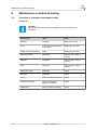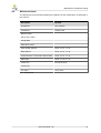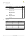
1
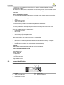
Service Manual
XP
V2.0 from Jan. 1st 2015
Copyright
(C) 2015 Handicare BV
All rights reserved.
The information provided may not be reproduced and/or published in any form, or by
any other means whatsoever( electronically or mechanically) without the prior written
authorization of Handicare BV.
The information provided is based on general data about the constructions known at the
time of the publication of this manual. Handicare BV strives to continuous product
improvement and reserves the right to changes and modifications.
The information provided is valid for the product in its standard version. Handicare BV
cannot be held liable for possible damage resulting from specifications of the product
deviating from the standard configuration.
The available information has been prepared with all possible care, but Handicare BV
cannot be held liable for possible errors in the information or the consequences thereof.
Handicare BV accepts no liability for loss resulting from work that is executed by third
parties.
The names, trade names, etc. used by Handicare BV may not, according to the
legislation concerning the protection of trade names, be considered as being available.
Table of contents
Table of contents
Copyright
1. Introduction
1.1. Scope of this manual
1.2. Reference documentation
1.3. Symbols used in this manual
1.4. Guidelines and useful information for maintenance
1.5. Product identification
5
5
5
5
5
6
2. Warranty and Liability
2.1. Warranty
2.2. Liability
7
8
9
3. Safety
3.1. Maximum user weight reduction when EQLASS is installed on an XP
3.2. Personnel qualifications
3.3. Cautions and warning statements
3.4. Pictograms on the wheelchair
10
10
10
10
11
4. Maintenance schedule & tooling
4.1. Overview of scheduled maintenance tasks
4.2. Mechanical tools
4.3. Electronical tools
4.4. Torque table
12
12
13
14
14
5. Maintenance tasks & adjustments
5.1. General preparations for maintenance
5.2. Carrier
5.2.1.
Replace the carbon brushes
5.2.2.
Replace a drive motor
5.2.3.
Replace a drive wheel
5.2.4.
Replace a castor wheel
5.2.5.
Replace a castor fork
5.2.6.
Replace the batteries
5.2.7.
Replace main fuse
5.3. Interface (all types)
5.3.1.
Adjust the position of the interface
5.3.2.
Adjust the base height of the interface
5.4. Tilt-only interface
5.4.1.
Replace the Tilt Actuator (Tilt-only Interface)
5.5. Tilt + lift interface
5.5.1.
Replace the tilt actuator
5.5.2.
Replace lift actuator
5.6. Legrests
5.6.1.
Replace the actuator of a powered Legrest
5.6.2.
Replace the gasspring of a comfort legrest
5.6.3.
Replace the actuator of the central legrest
5.6.4.
Replace the motor of the central legrest
5.7. Seating system QLASS
5.7.1.
Replace the actuator of the backrest
5.7.2.
RepIace the tilt actuator 25 degrees
5.8. Seating system EQLASS
5.8.1.
Replace the actuator of the backrest
5.8.2.
RepIace the tilt actuator
5.9. General completion of maintenance
15
15
17
17
17
19
19
20
20
21
22
22
23
23
23
24
24
24
25
25
25
26
26
27
27
28
28
28
29
30
3
Table of contents
6. Maintenance on the control system
6.1. Replace the remote control (Shark, VR2 and R-Net)
6.2. Replace the remote control (DX2)
6.3. Replace the power module (Shark, VR2 and R-Net)
6.4. Replace the power module (DX2)
32
32
32
32
32
7. Troubleshooting
7.1. General diagnostics and faultfinding
7.2. Diagnostics and troubleshooting for Shark controls
7.3. Diagnostics and troubleshooting for DX2 controls
34
35
40
43
8. Cable and module schemes
8.1. Shark controls
8.2. DX2 controls
47
47
50
9. Version history
54
4
Introduction
1.
Introduction
1.1.
Scope of this manual
This service manual contains information and instructions about general maintenance and
repairs of this electric wheelchair.
This service manual is meant for:
•
•
1.2.
Service technicians: personnel that performs the regular maintenance and that solves
technical problems to the wheelchair.
Only service technicians that have completed the equipment training for this
wheelchair are allowed to do maintenance on this wheelchair.
Customer support personnel at Handicare BV dealers: personnel that support
customers when customers call to the dealer's office with questions about the
wheelchair.
For customer support this manual serves as reference material.
Reference documentation
This service manual refers, where necessary, to one of the other manuals that are available
for this wheelchair.
•
User manual wheelchair: for general information about the use of the wheelchair.
•
User manual for the electronics: for detailed information about the use of the controller
of the wheelchair.
•
User manual for the seating system: for detailed information about the user
adjustments and the use of the seating system.
•
Spare parts manual: for information about the spare parts and their ordering numbers.
•
Supplier documentation for the electronics: for detailed information about changing
settings and doing repairs on the controls of the wheelchair.
1.3.
Symbols used in this manual
This manual uses the following symbols to highlight information that needs extra attention.
WARNING!
Follow the instructions next to this symbol closely.
Not paying careful attention to these instructions could result in physical injury
or damage to the wheelchair or to the environment.
NOTICE!
This provides useful background information.
1.4.
Guidelines and useful information for maintenance
Service technicians
Maintenance (regular maintenance and repairs) to the wheelchair may only be done by
service technicians that have been trained and authorised by Handicare BV. Temporary
employees and personnel in training are also allowed to do this work but only under the
supervision of an authorised service technician.
Work safely
Always make sure that you work safely, particularly when you need to lift up the wheelchair.
During maintenance and repair work you are at all times fully responsible to obey the local
applicable guidelines and standards with regard to safety and environment. We advise you
Service manual - XP
5
Introduction
to contact our service department before you do repairs to a wheelchair that has been
involved in an accident.
We advise you to disconnect the wheelchair from the battery power, if the wheelchair has to
be repaired because of a fault condition. Remove the main fuse(s) while the wheelchair is
unattended.
Service and technical support
For information about settings, maintenance and repair works, please contact you supplier.
Make sure you have the following information at hand:
•
Type
•
Identification number
•
Year of manufacture
This information is printed on the identification plate of the wheelchair.
How to order spare parts
For spare parts please use the Spare part manual to see what part numbers you need.
When you order spare parts, please specify:
•
Identification number
•
Part number
•
amount of parts you need
•
description (in the relevant language)
•
dimensions (if applicable)
Please use e-mail or fax to send your orders to your supplier.
Remarks:
•
Parts that do not have a position number cannot be ordered separately. Such parts
belong to an assembly that must be ordered and replaced as one piece.
•
Boxed position numbers refer to the relevant separate drawing.
Disposal
Always handle waste materials according to the local regulations.
Contact information Handicare BV
Handicare BV
Vossenbeemd 104
5705 CL Helmond
The Netherlands
T +31 (0)492 59 38 88
F +31 (0)492 53 79 31
www.handicare.com
[email protected]
1.5.
Product identification
Handicare BV 6002342 A
Vossenbeemd 104
5705 CL HELMOND
THE NETHERLANDS
A B
A. Model
B. Year of manufacture
C. Identification number
6
TYPE/TYPE/TYP:
You-Q Luca Qlass
YEAR/JAAR/JAHR:
2015
USAGE:
INDOOR/OUTDOOR
GEBRUIKSGEBIED:
BINNEN/BUITEN
C
LUQ1400520
GEBRAUCHSGEBIET: INNERHALB/AUSSERHALB
MAX.LOAD/MAXBELASTB./ZUL.GESAMTGEW.: 160 KG
D
E
D. Usage area
E. Maximum load in kg
Service manual - XP
Warranty and Liability
2.
Warranty and Liability
In the following warranty and liabilty stipulations the following terms are used:
•
•
•
•
Product: the electric wheelchair manufactured Handicare BV.
User: the person who actually uses the product.
Customer: the person who obtains the product from Handicare BV.
Dealer: the person/company who supplies the product from Handicare BV to the
customer.
Service manual - XP
7
Warranty and Liability
2.1.
Warranty
1.
2.
3.
4.
5.
6.
7.
8.
8
Save in so far as the following provisions stipulate otherwise, Handicare BV warrants
to the Customer or user of the Product that the Product is sound and fit for the purpose
for which the Product is intended to be used – as set forth in the user’s manual of the
Product. Handicare BV furthermore warrants the quality of the material used to
manufacture the Product as well as the quality of the manufacturing process.
Handicare BV shall replace parts of the Product which are defective due to faulty
materials or manufacturing defects on free of cost basis, provided that such defects
arise within one (1) year after the date of delivery of the Product to the Customer.
Consequently, the following shall be excluded from the scope of free replacement as
meant in the preceding sentence:
a) replacement of parts of the Product required on account of defects arisen more
than one (1) year after the date of delivery of the Product to the Customer;
b) replacement of parts of the Product required on account of defects resulting due to
improper or careless use of the Product or resulting due to using the Product for a
purpose other than the intended purpose; if a Dealer is a Customer, this Customer
shall save Handicare BV harmless from and against any claims by Users or other
third parties for defects resulting due to improper or careless use of the Product;
c) parts subject to wear and tear, and the repair/replacement of these parts is the
result of normal wear and tear;
d) without prejudice to the provisions of article 2, the warranty with respect to the
battery of the electric wheelchair only covers instances of malfunctioning or nonfunctioning which are evidently the direct result of material defects or
manufacturing defects. The warranty as set out in these provisions does not cover
a battery which is malfunctioning or non-functioning due to normal wear and tear
or due to improper or incompetent use of the Product or the battery forming part of
the Product, including the improper charging of the battery and the failure to
perform timely and proper maintenance; the Customer shall save Handicare BV
harmless from and against any claims by Users or other third parties for defects
resulting due to improper or careless use of the Product or the battery forming part
thereof. This includes damage resulting due to the leakage of battery acid when
performing maintenance to (wet) batteries.
The warranties as explained in the preceding provisions shall in any event cease to be
effective if:
a) the Product maintenance guidelines drawn up by Handicare BV have been
observed not at all or to an insufficient extent;
b) repair/replacement of parts results from neglecting, damaging or overburdening
the Product or using the Product for purposes other than its intended purpose;
c) parts of the Product have been replaced by parts not of the same origin as those
used by Handicare BV and/or parts of the Product have been replaced without
authorisation by Handicare BV
The warranties as set forth in articles 1 up to and including article 3 above shall
become null and void if the Product is reused by a new User within the warranty period
and that reuse necessitated modifications, of whatever kind, to the Product, which
modifications were not authorised or performed by and/or on the instructions of
Handicare BV
The above warranty shall also become null and void if through the agency of the
Customer, in instances other than those mentioned in article 4, our Products have
been altered in such way as to cause our Products to malfunction.
In the event of damage or other calamities the User or the Customer must contact
Handicare BV as soon as possible and provide the most extensive information possible
if they wish to retain their rights under the warranty set out above. The possibility to
lodge a claim under the above warranties shall lapse upon expiry of a period of twenty
(20) days after the damage or calamity occasioning the claim arose.
The replacement of a part or the repair or reconditioning of the Product during a
warranty period shall not extend the warranty period.
Any repair to or reconditioning of the Product not authorised or performed by and/or on
the instructions of Handicare BV shall not be covered by the scope of this warranty. If a
Service manual - XP
Warranty and Liability
User has authorised or performed and/or instructed the repair or reconditioning of a
Product, the Customer shall save Handicare BV harmless from and against any claims
by third parties following – in the widest sense – from such repair or reconditioning.
9. In consideration of the matters considered in the preceding paragraphs of this article 9,
the following parts subject to wear and tear or breakage risk shall in any event be
excluded from the scope of free repair/replacement unless the breakage and/or wear
and tear has been caused by faulty materials and/or manufacturing defects:
a) foot plates and/or foot rests;
b) carbon brushes;
c) upholstery of the seat;
d) frame covers, rain covers and other covers, apron, winter cover, immobilisation
waistcoats, cross straps, sitter’s pants and other similar accessories;
e) tyres;
f) damage to breakable materials such as lamps and other parts qualifying as
vulnerable.
Depending on the other specifications of the Product, this list may be extended on
the basis of a list possibly attached to these terms and conditions (Schedule 1).
10. In the event that a User lodges a claim under a warranty with a Customer or that a
Customer lodges such claim, Handicare BV shall be notified immediately.
11. If Handicare BV has determined a claim under the warranty to be justified, the costs of
transport to Handicare BV will be borne by the Customer, the costs of transport to the
Customer will be borne by Handicare BV
2.2.
Liability
1.
2.
3.
4.
5.
6.
7.
Subject to the following provisions, Handicare BV only assumes liability for damage
arising out of death or bodily injury due to a defect in the Product for which Handicare
BV is liable and for damage to another good owned by the User of the Product in a
private capacity, provided that such damage is the direct result of a defect in the
Product.
Handicare BV shall indemnify for damage as referred to in article 1 up to the sum
covered by its statutory liability insurance taken out with its insurance company.
Handicare BV shall not assume any other or additional liability than the liability set out
in article 1. In particular, Handicare BV shall not assume any liability for consequential
damage in whatever form.
In so far as Handicare BV – notwithstanding the provision of article 3 – is ordered by a
Netherlands court or in any other forum for the settlement of disputes to pay damages
other than referred to in article 1, Handicare BV shall make indemnification in
accordance with the provisions of article 2.
Handicare BV shall not assume liability for damage resulting due to repair or
replacement required to remedy defects caused by improper or careless use of the
Product or caused by modifications made by the Customer or User which were not
authorised or performed by and/or on the instructions of Handicare BV
The Customer shall save Handicare BV harmless from and against any claims by
Users under the warranty provisions referred to in Article 9 or claims for liability under
mandatory law if the Customer or third parties have made modifications which are not
in accordance with the supplied instructions and/or which have been made using the
wrong materials, unless this failure to observe the instructions or use the right
materials is based on an error in the technical manual or other instructions imparted by
Handicare BV
The Customers shall likewise save Handicare BV harmless from any against any
liability resulting due to representations made by the Customer with regard to the
Product which are incompatible with the quality or the normal use of the Product.
Service manual - XP
9
Safety
3.
Safety
3.1.
Maximum user weight reduction when EQLASS is installed on an XP
When an EQLASS seating system is installed on an XP, the maximum user weight is
reduced to 136 kg.
3.2.
Personnel qualifications
Only service technicians that are trained and authorised by Handicare BV are allowed to do
maintenance and repairs to the wheelchair.
Temporary employees and persons in training are only allowed to do the maintenance and
repairs to the wheelchair if they work under the supervision of an authorised service
technician.
3.3.
Cautions and warning statements
Safety information
•
Safety information is indicated with the warning symbol. Wherever possible, safety
information is provided in the relevant chapter.
Functionality
•
After repairing, reprogramming or replacing parts, always check the functionality of the
entire wheelchair. Pay special attention to safety features such as slowdown driving or
drive inhibits when seat lift and tilt are both used.
Temperature
•
•
Avoid physical contact with the wheelchair's motors at all times. Physical contact can
cause burns. Motors are continuously in motion during use and can reach high
temperatures. After use, the motors cool down slowly.
If the wheelchair is not in use, make sure that it is not exposed to direct sunlight for
lengthy periods of time. Some parts of wheelchair, such as the seat, the back and the
armrest can become hot if they have been exposed to full sunlight for too long. This
may cause burns or allergic reactions to the skin.
Programming
•
Programming should only be conducted by healthcare professionals with in-depth
knowledge of wheelchair control systems. Incorrect programming could result in an
unsafe set-up of the wheelchair for a user. Handicare BV accepts no responsibility for
losses of any kind if the programming of the control system is altered without
authorization of Handicare BV.
Seat adjustment factory settings
Handicare BV will deliver a wheelchair with default factory settings. These settings depend
on the options ordered with the wheelchair. When a configuration is ordered that causes
interference, Handicare BV applies modified settings.
Moving parts
•
10
Contact with moving parts of the wheelchair should be avoided. Contact with moving
parts can result in serious physical injury or damage to the wheelchair. Pay attention to
the following parts:
•
Wheels (drive and castor)
•
Electric tilt in space adjustment
•
Electric high/low option
•
Electric back adjustment
•
Electric legrest
Service manual - XP
Safety
Electromagnetic radiation
The standard version of the electric wheelchair has been tested on the applicable
requirements with respect to electromagnetic radiation (EMC requirements). In spite of
these tests:
•
it cannot be excluded that electromagnetic radiation can have influence on the
wheelchair. For example:
•
mobile telephony
•
large scale medical apparatus
•
other sources of electromagnetic radiation
•
it cannot be excluded that the wheelchair can interfere with electromagnetic fields. For
example:
•
shop doors
•
burglar alarm systems in shops
•
garage door openers
In the unlikely event that such problems occur, contact your supplier immediately.
Pictograms on the wheelchair
A B
Handicare BV 6002342 A
Vossenbeemd 104
5705 CL HELMOND
THE NETHERLANDS
3.4.
A
B
C
D
TYPE/TYPE/TYP:
You-Q Luca Qlass
YEAR/JAAR/JAHR:
2015
USAGE:
INDOOR/OUTDOOR
GEBRUIKSGEBIED:
BINNEN/BUITEN
C
LUQ1400520
GEBRAUCHSGEBIET: INNERHALB/AUSSERHALB
MAX.LOAD/MAXBELASTB./ZUL.GESAMTGEW.: 160 KG
check manual before using.
Danger of crushing
Be careful when swinging the controller
aside to avoid getting anything
crushed.
Battery charging connection
Attachment point of the tie down
system for transportation on a vehicle.
Service manual - XP
E
F
G
D
E
Freewheel switch
Do not put the freewheel switch in
'Push' mode on a slope.
Trap danger
Danger of getting fingers jammed.
Identification plate
11
Maintenance schedule & tooling
4.
Maintenance schedule & tooling
4.1.
Overview of scheduled maintenance tasks
No Spares
NOTICE!
The wheelchair must be checked regularly by an authorized service
technician.
12
System Unit
Task
Limit
Batteries
Charging
Daily (by the user)
Tyres
Check pressure and inflate
if necessary
Weekly (by the user)
Wheelchair and upholstery
Clean
Weekly (by the user)
Electrical system
Inspection
Twice a year / every 6
months
Batteries
Inspection
Twice a year / every 6
months
Drive
Inspection
Twice a year / every 6
months
Mechanical parts
Inspection
Yearly
Bearings
Inspection
Yearly
Tyres
Check condition and profile
Yearly
Fasteners and bolts
Check condition and
tighten if necessary
Yearly
Wheelchair
Check overall functionality
Yearly
Service manual - XP
Maintenance schedule & tooling
4.2.
Mechanical tools
The following tools and general supplies are needed to do the maintenance as described in
this manual:
Description
Remark
Screwdriver
size: medium
Screwdriver
Phillips head
Rubber mallet
Pair of wire cutters
Circlip pliers
Waterpump pliers
Open ended spanner
sizes: 10, 13, 17, 19
Ring spanner
sizes: 10, 13, 17, 19
Torque wrench, up to 60 Nm with sockets
sizes: 10, 13, 17, 19
Allen keys
sizes: 3, 4, 5, 6, 7, 8
Loctite 270
for bolt securing
Loctite 648
Tie wraps
color: black
n/a: not applicable
Service manual - XP
13
Maintenance schedule & tooling
4.3.
Electronical tools
The following tools and general supplies are needed to do the maintenance as described in
this manual:
Part number
Description
DX2
DX
Shark
00355.0440
Dynamic Hand Held
Programmer (DX-HHPGDW)
x
x
x
1003236
Dynamic Wizard USB set
OEM (DWIZ-KIT + DWDOEM-U)
x
6000668
Dynamic Wizard USB set
dealer (DWIZ-KIT + DWDDLR-U)
x
9003295
PGDT R-Net programmer
OEM (D50611)
6000614
GDT VR2 PC-Programmer
B set (D50145)
Universal meter (voltage
and resistance
4.4.
RNet
VR2
x
x
x
x
x
x
x
x
Torque table
Use the general torques as indicated in the table below, unless specified otherwise
Thread Size
Pitch (mm)
Max. torque (Nm)
M4
0.7
3
M5
0.8
6
M6
1
10
M8
1.25
25
M10
1.5
50
M12
1.75
80
M14
2
120
The minimum torque values are 7 - 9 % below the maximum values.
14
Service manual - XP
x
Maintenance tasks & adjustments
5.
Maintenance tasks & adjustments
5.1.
General preparations for maintenance
This chapter describes the general preparations that apply for all maintenance and repairs
to the wheelchair.
WARNING!
Only do maintenance on an empty wheelchair.
NOTICE!
The frames of the wheelchair differ per drive type (FWD or RWD). Most
illustrations in this manual show the FDW drive. For most maintenance tasks
the difference in drive type does not matter. In case that is does matter, this is
clearly shown in this manual.
1.
2.
3.
Switch off the wheelchair via the button on the controller.
Set both freewheel switches in 'Drive' mode.
Tilt the interface mounting frame forward for
easy access as follows:
a. Remove the screws A.
b. Tilt the frame (B) until it locks in the tilted
position.
B
A
4.
Remove the battery cover.
B
A
C
Service manual - XP
15
Maintenance tasks & adjustments
5.
Remove the power module cover.
A
6.
Disconnect the batteries by removing the
main fuses (A).
A
7.
Disconnect the motor cable (A) from the
interconnection of the power module.
A
16
Service manual - XP
Maintenance tasks & adjustments
5.2.
Carrier
5.2.1.
Replace the carbon brushes
Preparation
See section 5.1.
Procedure
1.
Remove the cap (A).
2.
Remove the old carbon brush (B).
3.
Gently blow some air through the hole (to
remove any dust).
4.
Put the new carbon brush in the motor.
5.
Put the cap on the motor.
6.
Repeat steps 1 through 5 for all the carbon
brushes on the motor.
A
B
Completion
See section 5.9.
5.2.2.
Replace a drive motor
Preparation
See section 5.1.
Procedure
1.
Remove cap A.
2.
Unfold the washer (D).
3.
Remove screw B and washer C.
4.
Remove the drive wheel (E) from the motor
axle.
•
Make sure that you do not loose the
key (F).
F
B
E
D
5.
C
B
A
Replace the drive motor, depending on the drive type:
•
FWD: see step 6.
•
RWD: see step 7.
Service manual - XP
17
Maintenance tasks & adjustments
6.
For FWD (Front Wheel Drive):
a. Remove the screws, washers and nuts A.
b. Remove the old drive motor (C).
c. Install the new motor. Use the screws and
nuts that are enclosed with the new motor.
d. Proceed with step 8.
C
A
A
7.
For RWD (Rear Wheel Drive):
a. Remove the screws, washers and nuts A.
b. Remove the bracket F for easy access.
c. Remove the old drive motor (C).
d. Install the new motor. Use the screws
and nut that are enclosed with the new
motor.
e. Proceed with step 8.
D
E
F
B
A
8.
Install the drive wheel.
a. Put some grease on the axle to prevent fretting.
b. Mount the drive wheel on the axle.
c. Make sure to lock the nut by folding the washer.
9.
Make sure that the drive wheel does not interfere with the motor.
Completion
See section 5.9.
18
Service manual - XP
C
Maintenance tasks & adjustments
5.2.3.
Replace a drive wheel
Preparation
See section 5.1.
Procedure
1.
Lift the wheelchair until the wheels are free from the floor.
•
Use a lifting platform.
2.
Remove the screws (A).
3.
Remove the old drive wheel (B).
4.
Install the new drive wheel.
5.
Make sure that the drive wheel does not
interfere with the motor.
B
A
Completion
See section 5.9.
5.2.4.
Replace a castor wheel
Preparation
See section 5.1.
Procedure
1.
Lift the wheelchair until the wheels are free from the floor.
•
Use a lifting platform.
2.
Remove screw, washer and nut A.
3.
Take out the old castor wheel (B) from the
castor fork.
4.
Install the new castor wheel.
•
Use a new lock nut.
A
B
Completion
See section 5.9.
Service manual - XP
19
Maintenance tasks & adjustments
5.2.5.
Replace a castor fork
Preparation
1.
Prepare the wheelchair for maintenance. See section 5.1.
2.
Remove the castor wheel. See section 5.2.4.
Procedure
1.
Lift the wheelchair until the wheels are free from the floor.
•
Use a lifting platform.
2.
Replace the castor fork, depending on the date of manufacture:
•
Manufactured before December 2013: see step 3.
•
Manufactured from December 2013: see step 4.
3.
Manufactured before December 2013:
a. Remove screw A and cap B.
b. Remove screw C.
c. Remove the old castor fork (F).
B
d. Install the new castor fork and use some
D
Loctite 648 to secure screw C.
A
E
F
C
4.
Manufactured from December 2013:
a. Remove screw A and cap B.
b. Remove cotter pin E.
c. Remove screw C.
d. Remove the old castor fork (G).
e. Install the new castor fork. Use a new
cotter pin and make sure that it is well
secured.
D
B
E
A
G
F
C
Completion
1.
Install the castor wheel. See section 5.2.4.
2.
Complete the maintenance. See section 5.9.
5.2.6.
Replace the batteries
Preparation
See section 5.1.
Procedure
NOTICE!
The illustration in this procedure shows the 31Ah battery pack. The 40Ah
battery pack is larger and has two straps.
20
Service manual - XP
Maintenance tasks & adjustments
1.
Disconnect the power cables (B).
B
2.
3.
4.
5.
Loosen the battery straps (A).
Remove the old batteries (B).
Put the new batteries in the carrier.
Connect the power cables.
B
WARNING!
See the 'cables and
module schemes' in
section 8.
6.
A
A
Tighten the battery straps and make sure
that the power cables are properly placed
underneath the battery straps.
WARNING!
Make sure that the
battery straps are tight.
Completion
See section 5.9.
5.2.7.
Replace main fuse
Preparation
See section 5.1.
Procedure
1.
Remove the old fuses (A).
2.
Put the new fuses in the fuse holders.
A
Completion
See section 5.9.
Service manual - XP
21
Maintenance tasks & adjustments
5.3.
Interface (all types)
5.3.1.
Adjust the position of the interface
The position of the interface can be adjusted in order to give the wheelchair better driving
characteristics. This position depends on the seat depth (as set on the seating system) and
the drive type (front wheel drive, mid wheel drive or rear wheel drive).
Preparation
1.
Set the interface in the maximum tilted position for easy access.
2.
Switch off the wheelchair via the button on the controller.
3.
Set both freewheel switches in 'Drive' mode.
4.
Disconnect the interface cables from the controller.
Procedure
1.
Loosen the screws A (4x).
RWD / MWD
RWD / MWD
2.
Remove the screws (A) and mounting
blocks (C) on one side of the wheelchair.
3.
Move the interface to the desired new
FWD
FWD
position.
WARNING!
Only use the positions
that match the drive type
(RWD: Rear wheel drive,
MWD: Mid wheel drive,
FWD: Front wheel drive).
4.
5.
6.
22
A
A,B
Put back the mounting blocks and screws
that you removed earlier.
Make sure that the interface is firmly locked
by the mounting blocks and fasten the
screws (A).
Check if the wheelchair is stable in all
available positions for seat lift and tilt.
Service manual - XP
B
Maintenance tasks & adjustments
5.3.2.
Adjust the base height of the interface
The height of the interface can be adjusted in order to achieve the seat height as required
for the user.
Preparation
1.
Switch off the wheelchair via the button on the controller.
2.
Set both freewheel switches in 'Drive' mode.
3.
Remove the interface, including the seating system from the wheelchair, for easy
access.
Procedure
1.
Set the front side of the interface mounting
frames (B) to the required height.
2.
Set both brackets on the back side of the
B
interface mounting frames to the required
height.
3.
Fasten the screws.
4.
Put the seating in its original place.
5.
Make sure to lock the interface mounting
frames (screws A).
6.
Check if the wheelchair is stable in all
available positions for seat lift and tilt.
A
5.4.
Tilt-only interface
5.4.1.
Replace the Tilt Actuator (Tilt-only Interface)
Preparation
1.
Set the interface in the maximum tilted position for easy access.
2.
Prepare the wheelchair for maintenance. See section 5.1.
3.
Disconnect the interface cables from the controller.
Procedure
1.
Make sure that the interface is kept in the
tilted position. For instance by placing a
support.
2.
Disconnect the actuator cable.
3.
Remove the circlips (B) from the pivot (C) at
both ends of the actuator (A).
4.
A
WARNING!
Make sure that the tilt
mechanism is supported
safely.
5.
6.
7.
8.
C B
Remove the old actuator.
Put the new actuator into the tilt
mechanism.
Connect the actuator cable.
Make sure that the actuator cable can follow
the movement of the mechanism but that
the cable does not get jammed by the
mechanism.
Check the functionality of the actuator.
Service manual - XP
23
Maintenance tasks & adjustments
5.5.
Tilt + lift interface
5.5.1.
Replace the tilt actuator
Preparation
1.
Set the interface in the maximum tilted position for easy access.
2.
Prepare the wheelchair for maintenance. See section 5.1.
3.
Disconnect the interface cables from the controller.
Procedure
1.
Make sure that the interface is kept in the
tilted position. For instance by placing a
support.
2.
Disconnect the actuator cable.
3.
WARNING!
Make sure that the tilt
mechanism is supported
safely.
4.
5.
6.
7.
8.
5.5.2.
A
C
B
Remove the circlips (B) at the pivot (C) at
the end of the actuator.
Remove the old actuator (A).
Put the new actuator into the tilt
mechanism.
Connect the actuator cable.
Make sure that the actuator cable can follow
the movement of the mechanism but that
the cable does not get jammed by the
mechanism.
Check the functionality of the actuator.
Replace lift actuator
Preparation
1.
Set the interface in the maximum lift position for easy access.
2.
Prepare the wheelchair for maintenance. See section 5.1.
3.
Disconnect the interface cables from the controller.
Procedure
1.
Make sure that the interface is kept in the
upper position. For instance by placing a
support.
D
2.
Disconnect the actuator cable.
3.
WARNING!
Make sure that the lift
mechanism is supported
safely.
4.
5.
6.
7.
8.
24
D
Remove the circlips (B) from the pivots (C
and D).
Remove the old actuator (A).
Put the new actuator into the tilt
mechanism.
Connect the actuator cable.
Make sure that the actuator cable can follow
the movement of the mechanism but that
the cable does not get jammed by the
mechanism.
Check the functionality of the actuator.
Service manual - XP
C B
A
Maintenance tasks & adjustments
5.6.
Legrests
5.6.1.
Replace the actuator of a powered Legrest
Preparation
1.
Lift the legrest out of the wheelchair.
Procedure
1.
Remove the tie wraps and disconnect the
actuator cable from the legrest.
2.
Remove the screws and nuts (B and C).
3.
Remove the old actuator (A) from the
legrest.
4.
Put the new actuator in the legrest.
5.
Connect the actuator cable to the legrest.
6.
Put the connector cable into the groove of
the legrest and fasten the connector cable
with tie wraps.
Make sure that you leave enough free cable
length to let the actuator reach its full length.
7.
Check the functionality of the actuator.
5.6.2.
C
B
A
Replace the gasspring of a comfort legrest
Preparation
1.
Lift the legrest out of the wheelchair.
Procedure
1.
Remove the screws and nuts (B and C).
2.
Remove the old actuator (A) from the
legrest.
3.
Remove the lever block (D) from the
gasspring (A). The lever block is re-used
with the new gasspring.
4.
Put the level block on the new gasspring.
5.
Put the new actuator in the legrest.
6.
Check the functionality of the actuator.
C
B
D
A
Service manual - XP
25
Maintenance tasks & adjustments
5.6.3.
Replace the actuator of the central legrest
Preparation
See section 5.1.
Procedure
1.
Remove the seat cushion for easy access.
2.
Disconnect the actuator cable.
3.
Remove the circlips from the pivot (A).
4.
Remove the screw (B).
5.
Remove the old actuator (C).
6.
Put the new actuator into the wheelchair.
7.
Connect the actuator cable.
8.
Make sure that the actuator cable is
properly arranged. Use tie wraps.
9.
Put the seat cushion in the wheelchair.
10. Check the functionality of the actuator.
B
C
A
5.6.4.
Replace the motor of the central legrest
Preparation
See section 5.1.
Procedure
1.
Remove the seat cushion for easy access.
2.
Disconnect the motor cable.
3.
Loosen the locking screw (A).
4.
Remove the old motor (C) from the legrest
by removing screws B.
5.
Put the new motor in the legrest.
6.
Fasten the locking screw.
7.
Connect the motor cable.
8.
Make sure that the motor cable is properly
arranged. Use tie wraps.
9.
Put the seat cushion in the wheelchair.
10. Check the functionality of the actuator.
26
C
Service manual - XP
A
B
Maintenance tasks & adjustments
5.7.
Seating system QLASS
5.7.1.
Replace the actuator of the backrest
Preparation
See section 5.1.
Procedure
1.
Remove the seat cushion for easy access.
2.
Make sure that the backrest is kept in the
upright position. For instance by placing a
support.
3.
Disconnect the actuator cable.
4.
WARNING!
Make sure that the
backrest is supported
safely to prevent it from
falling backwards.
5.
6.
7.
8.
9.
10.
Remove the mounting clip (B).
Remove the nut (C).
Remove the old actuator (A).
Remove screw, washers and nut (D).
Remove the mounting fork from the
actuator. The mounting fork is re-used with
the new actuator.
Put the mounting fork on the new actuator.
Put the new actuator into the seating
mechanism. Use a new lock nut (C) and
fasten the mounting clip (B).
E
A
D
B
C
WARNING!
Make sure that the
mounting clip (B) is
correctly locked on the
actuator. This prevents
the clip from loosening
which in turn might cause
the backrest to fall
backwards.
11.
12.
13.
14.
Connect the actuator cable.
Make sure that the actuator cable is
properly arranged on the seating system.
Check the functionality of the actuator.
Put the seat cushion on the wheelchair.
Service manual - XP
27
Maintenance tasks & adjustments
5.7.2.
RepIace the tilt actuator 25 degrees
Preparation
1.
Set the seat in the maximum tilted position for easy access.
2.
See section 5.1.
Procedure
1.
Make sure that the seat is kept in the tilted
E
position. For instance by placing a support.
A
2.
Remove the seat cushion for easy access.
3.
Disconnect the actuator cable.
4.
Remove the circlips (A) from the pivots B at
both ends of the actuator (F).
5.
WARNING!
Make sure that the tilted
seat is supported safely.
C
B
A
F
C
A
6.
7.
8.
9.
Remove the old actuator.
Put the new actuator into the tilt
mechanism.
Connect the actuator cable.
Make sure that the actuator cable can follow
the movement of the mechanism but that
the cable does not get jammed by the
mechanism.
Check the functionality of the actuator.
5.8.
Seating system EQLASS
5.8.1.
Replace the actuator of the backrest
Preparation
See section 5.1.
Procedure
1.
Remove the seat cushion for easy access.
2.
Disconnect the actuator cable from the
actuator.
3.
WARNING!
Make sure that the
backrest is in a horizontal
position and that is
supported in this position.
4.
5.
6.
7.
8.
9.
28
Remove the mounting clip (B).
Remove the screw, washer and nut (C).
Remove the old actuator (A).
Remove screw, washers and nut (D).
Remove the mounting fork (E) from the
actuator. The mounting fork is re-used with
the new actuator.
Put the mounting fork on the new actuator.
Put the new actuator into the seating
mechanism.
Service manual - XP
B
A
D
E
B
D
A
C
Maintenance tasks & adjustments
WARNING!
Make sure that the
mounting clip (B) is
correctly locked on the
actuator. This prevents
the clip from loosening
which in turn might cause
the backrest to fall
backwards.
10.
11.
12.
13.
5.8.2.
Connect the actuator cable.
Make sure that the actuator cable is
properly fixed to the seating system.
Put the seat cushion on the wheelchair.
Check the functionality of the actuator.
RepIace the tilt actuator
Preparation
1.
Set the seat in the maximum tilted position for easy access.
2.
See section 5.1.
Procedure
1.
Make sure that the seat is kept in the tilted
position. For instance by placing a support.
2.
Remove the seat cushion for easy access.
3.
Disconnect the actuator cable.
4.
Remove the circlips (C) from the pivots (B)
at both ends of the actuator (A).
5.
WARNING!
Make sure that the tilted
seat is supported safely.
A
6.
7.
8.
9.
Remove the old actuator.
Put the new actuator into the tilt
mechanism.
Connect the actuator cable.
Make sure that the actuator cable can follow
the movement of the mechanism but that
the cable does not get jammed by the
mechanism.
Check the functionality of the actuator.
Service manual - XP
B
C
29
Maintenance tasks & adjustments
5.9.
General completion of maintenance
This chapter describes the general instructions for completion of maintenance that apply to
all maintenance and repairs to the wheelchair.
1.
Connect the motor cable to the power
module.
2.
Connect the main fuses.
3.
Close the power module cover, make sure
A
that it is well positioned.
4.
Install the battery cover and fasten the
screws. Make sure that the power module
cover is properly placed underneath the
battery cover.
B
A
C
5.
Put the interface mounting frame down
again.
B
A
30
Service manual - XP
Maintenance tasks & adjustments
6.
WARNING!
Make sure that the
interface mounting frame
is well secured.
B
Fasten screws A in order to secure the
interface mounting frame.
A
WARNING!
After repairing, reprogramming or replacing parts, always check the
functionality of the entire wheelchair. Pay special attention to safety features
such as slowdown driving or drive inhibits when seat lift and tilt are both used.
Service manual - XP
31
Maintenance on the control system
6.
Maintenance on the control system
6.1.
Replace the remote control (Shark, VR2 and R-Net)
The driving program of the Shark, VR2 and R-Net controller systems is stored in the power
module. Replacing the remote control can therefore be done without any programming.
1.
Replace the remote control.
6.2.
Replace the remote control (DX2)
The DX2 system has the main driving program stored in the remote and a backup of the
program in the power module. Replacing the remote can be done without programming.
For REM420:
1.
Switch on the controls.
The actuator LEDs 1 and 4 flash (C). This
indicates that the remote control and the
power module have different programs.
2.
Replace the remote control.
3.
Press the "-" button on the actuator selecton
A
bar (D).
This way you select the backup program
B
from the power module.
C
4.
Simultaneously press the horn button (B)
4
1
and the "+" button on the drive profile
2 3
selection bar (A) for 3 seconds.
D
This confirms the selection and the system
will beep when confirmed.
5.
Switch the controls off and on again to
activate the new settings.
For REM550:
1.
Replace the remote control.
2.
Switch on the controls.
The display shows a selection sequence for the backup program.
3.
Replace the remote control.
4.
Select the module that has NOT been replaced.
The backup program from this module will be used to automatically re-programm the
new module.
6.3.
Replace the power module (Shark, VR2 and R-Net)
The driving program of the Shark, VR2 and R-Net controller systems is stored in the power
module.
1.
Make a backup of the driving program from the power module.
Use a laptop and programming software for this step.
2.
Replace the power module.
3.
Load the backup of the driving program in to the new power module.
4.
Check all functionality of the wheelchair.
6.4.
Replace the power module (DX2)
The DX2 system has the main driving program stored in the remote and a backup of the
program in the power module. Replacing the power module can be done without
programming.
For REM420:
32
Service manual - XP
Maintenance on the control system
1.
2.
Replace the power module.
Switch on the controls.
The actuator LEDs 1 and 4 flash (C). This
indicates that the remote control and the
power module have different programs.
3.
Press the "+" button on the actuator
A
selection bar (D).
This way you select the backup program
B
from the remote control.
C
4.
Simultaneously press the horn button (B)
4
1
and the "+" button on the drive profile
2 3
selection bar (A) for 3 seconds.
D
This confirms the selection and the system
will beep when confirmed.
5.
Switch the controls off and on again to
activate the new settings.
For REM550:
1.
Replace the remote control.
2.
Switch on the controls.
The display shows a selection sequence for the backup program.
3.
Replace the remote control.
4.
Select the module that has NOT been replaced.
The backup program from this module will be used to automatically re-program the
new module.
Service manual - XP
33
Troubleshooting
7.
Troubleshooting
This chapter contains table with troubleshooting information. One table shows the
troubleshooting for the wheelchair in general, the other tables show information about
troubleshooting for the available controls systems.
NOTICE!
If the problem is not solved with the help of the solutions in the tables, contact
your dealer/distributor or the Service Department of Handicare BV.
34
Service manual - XP
Troubleshooting
7.1.
General diagnostics and faultfinding
Problem
Cause
Solution
Wheelchair does not switch
on
Buscables not connected
Check buscable
connections of the joystick
module to the power
module (can also be
through the actuator
module!)
Pins in connectors are
loose or damaged
Check connectors for loose
or damaged pins. If
damaged replace cable.
Buscable defect
Check all bus cables for
damage. Bypass each
buscable with new one to
check functionallity.
Fuse defect / Thermal trip
Check fuses and replace if
needed.
Battery connections are
loose
Check battery connections
and restore if needed.
Battery voltage too low
Measure battery voltage
and charge batteries.
Battery defect
Measure battery voltage.
Voltage below 10 V can
indicate that one battery is
defect. Replace batteries.
Remote control or button
defect
Check by replacing with
new one.
Power Module defect
Check by replacing with
new one.
Speed limit due to
microswitch signal from
seating function.
Check if all seating options
are in neutral position.
Wheelchair continuously
drives slower than normal
Measure resistance from
the speed limit cable in
different seating positions.
Bad cable connections or a
broken resistor influences
the drive inhibit signal.
Incorrect programming
Service manual - XP
Check for correct program.
Re-program if needed.
35
Troubleshooting
Problem
Cause
Solution
Parking brake partially
engaged
Check parking brake
function. Clicking sound at
engaging/disengaging
should be present. Check
temperature of parking
brake after driving.
Poor batteries
Check batteries and battery
voltage.
Poor or incomplete battery
charging
Check battery charger.
Check charging duration
with the user.
Thermal rollback
(overheating)
Check usage of wheelchair,
extreme usage can cause
the power module to
decrease the maximum
currents for protection.
Check wheelchair in
freewheel mode for
extreme resistance on
rolling or turning.
(DX2 controls only)
Gyro module (if present) is
not connected correctly or
is not functioning properly
=> Controllers switch to
SystemSlowDown mode.
Check Gyro cabling and/or
replace Gyro module.
Wheelchair only drives well
for a short period of time.
Current limit is set too low
or the controller is
underspecified
Check program settings
and/or replace controller.
Wheelchair can be
powered up, but does not
drive.
Parking brakes are in
freewheel mode (flash code
on remote!)
Set parking brakes to Drive
mode.
Drive inhibits active (flash
code on remote)
Check program which Drive
inhibits are present. Check
cabling of Drive inhibits on
wheelchair.
Tyre pressure of drive
wheels or castors is too low
Check pressure and inflate
if needed. See User
manual for correct value.
Programming of speed and
Torque Settings is not
correct
Check programming and
make corrections if needed.
Wheelchair drives slower
throughout the day (or after
several hours)
Wheelchair has too little
power to drive properly
36
Service manual - XP
Troubleshooting
Problem
Wheelchair veers to one
side
Castor wheels "wobble" at
higher speed
Cause
Solution
Programming of Motor
Load Compensation is not
correct
Check programming and
make corrections if needed.
Check with manufacturer
for correct value.
Programming of Load
Compensation is not
correct.
Check programming and
make corrections if needed.
Motors are not "balanced"
Check motor rpm. See
motor label for correct
value.
Tyre pressure or tyre size
left and right are different
Check tyre pressure and
tyre size (diameter).
Suspension "hardness" left
and right are different.
Check suspensions and
make sure left and right
side have identical
suspension rates.
Carrier is not "in balance"
due to mechanical flaws
Check for loose bolts,
cracked or worn frame
parts. Check height of
carrier left and right.
User weight is not in the
center of the wheelchair
Check position of user, see
if position can be improved.
If not possible use veer
compensation in program
to correct the steering.
Chair stops intermittently
High Voltage due to
overcharging or driving
down slopes with full
batteries (regenerative
braking). Check battery
voltage, drive down slope
at lower speed.
Worn carbon brushes
Check brushes, replace if
needed.
Speed Limit due to micro
switch
Check functioning of microswitch. Due to vibrations or
shocks it can temporarily
switch to Slowdown mode.
Tyre pressure too high.
Check tyre pressure and
decrease if needed. See
user manual for correct
value.
Too little load on the castor
wheels.
Modify seating setup if
possible or decrease tyre
pressure.
Service manual - XP
37
Troubleshooting
Problem
Cause
Solution
Motors make excessive
noise
Worn carbon brushes
Check carbon brushes and
collector. If needed replace
brushes or motor.
Wheelchair wobbles overall
or moves up and down
when driving
Drive wheels have radial
misaligned tyres. Can be
caused by long (weeks)
inactive periods
Check for misalignment of
tyres. If misaligned, reduce
tyre pressure to 1 bar, drive
for several minutes at
moderate speed and
increase pressure again to
advised value.
Misalignment can be
reduced this way. If not
sufficient replace wheel.
Seating actuator does not
function
Current setting is not
correct
Check programming and
make corrections if needed.
Contact manufacturer for
correct settings.
Cables not connected or
cables damaged
Check cables and replace if
needed.
Wheelchair goes into fault
status when actuator is
operated
Actuator has a short circuit
that becomes active when
the actuator is operated.
Replace actuator.
Actuator inhibit is active
Check program to see what
actuator inhibit is present.
Check if inhibit signal is
functioning correctly.
(example : with lift and tilt
to maximum, recline will no
longer move backwards.
Actuator module (output)
fault
Try actuators on different
output channel to check
what output channel has a
fault.
Maximum current setting is
too low
Check programming and
make corrections if needed.
Contact manufacturer for
correct settings.
Actuator time out setting is
too short (or actuator speed
is too low)
Check programming and
make corrections if needed.
Contact manufacturer for
correct settings.
Actuator is internally not
functioning properly
Check actuator
temperature after operation
and/or check for excessive
noise when operated.
Replace actuator.
Seating actuator only
functions for a short time
38
Service manual - XP
Troubleshooting
Problem
Cause
Solution
Seating mechanism is
moving poorly or with
extreme friction
Check mechanisme on
loose bolts, cracked or bent
parts. Replace parts or
modules.
Seating actuator moves in
wrong direction (after
replacement)
Wiring connections
possibly twisted in cable or
motor
Change actuator direction
in driving program or
replace cable or part.
Lighting does not function
Cabling not (correctly)
connected
Check cabling. See wiring
diagrams for correct
connections.
Lighting settings not
correctly set in program
Check programming and
make corrections if needed.
Load compensation too
low, incorrect setting.
Modify load compensation
in driving program. Check
with manufacturer for
correct settings.
Too much load on front
castors (RWD).
Modify seating setup to
have better weight
distribution.
Load compensation is too
high.
Modify load compensation
in driving program. Check
with manufacturer for
correct settings.
Wheelchair moves/turns
very slowly and seems to
be lacking power
Wheelchair moves very
rapidly and jerky
Service manual - XP
39
Troubleshooting
7.2.
Diagnostics and troubleshooting for Shark controls
WARNING!
Remove both fuses from the batteries before you change any cables, fuses
and/or modules. This way the power way is disconnected from the wheelchair.
NOTICE!
For more detailed information about Shark Controllers, specific manuals can
be downloaded from the website: www.dynamiccontrols.com.
40
Service manual - XP
Troubleshooting
Problem
Cause
Solution
Service indicator flashes
once
User error.
This is probably a 'STALL'
timeout.
Put the joystick in neutral
and try again.
Service indicator flashes
twice
Battery fault.
Check batteries and
cabling. Charge the
batteries or replace them.
The ON-OFF light flashes 3
times.
The left-hand motor (m1)
connection is not good.
Check the connection and
the cabling.
The left-hand motor (m1) is
defect.
Replace this motor.
The right-hand motor (m2)
connection is not good.
Check the connection and
the cabling.
The m2 motor is defect.
Replace this motor
The left-hand parking brake
(m1) connection is not
good or disconnected.
Check the connection and
the cabling.
The left-hand parking brake
(m1) is defect.
Replace this motor.
The right-hand parking
brake (m2) connection is
not good or disconnected.
Check the connection and
the cabling.
The right-hand parking
brake (m2) is defect.
Replace this motor.
The ON-OFF light flashes 7
times
Controller fault
Check all connections and
correct them if needed.
If the fault signal is still
present after this, replace
the controller.
The ON-OFF light flashes 8
times
Power module fault
Check all connections and
correct them if needed.
If the fault signal is still
present after this, replace
the power module.
The ON-OFF light flashes 9
times
Communication fault in the
Shark system
Check all connections and
correct them if needed.
If the fault signal is still
present after this, replace
the controller.
The ON-OFF light flashes 4
times.
The ON-OFF light flashes 5
times
The ON-OFF light flashes 6
times
Service manual - XP
41
Troubleshooting
42
Problem
Cause
Solution
The ON-OFF light flashes
10 times
Unknown fault
Check all connections and
correct them if needed.
If the fault signal is still
present after this, contact
the Service Department of
Handicare BV.
The ON-OFF light flashes
11 times
System does not 'fit'.
System modules are not
compatible.
Check if the controller type
corresponds with the power
module. Replace one of the
two if needed.
Service manual - XP
Troubleshooting
7.3.
Diagnostics and troubleshooting for DX2 controls
WARNING!
Remove both fuses from the batteries before you change any cables, fuses
and/or modules. This way the power is disconnected from the wheelchair.
NOTICE!
For more detailed information about DX2 Controllers, specific manuals can be
downloaded from the website: www.dynamiccontrols.com.
Service manual - XP
43
Troubleshooting
44
Problem
Cause
Solution
ON-OFF light does not go
on; wheel and does not
move
Controller plug not properly
connected to the power
module.
Check the connection.
Both fuses are defect
Replace fuses.
The batteries are not
properly connected.
Check the connection.
ON-OFF light flashes once
DX module defect
Replace one or more
modules. The ON-OFF
LED shows the condition of
the system. All modules
have a separate status
LED, in this way you can
see which one is defect.
ON-OFF light flashes twice
DX accessory defect.
The module shows a fault
as a result of a
programming fault, or short
circuit and/or overload of
the accessories.
The (optional) electrical
high/low adjustment is not
in the lowest position. De
LED flashes twice to
indicate that the speed
limitation has been
switched on; the wheelchair
will drive considerably
slower.
The ON-OFF light flashes 3
times.
The left-hand motor (m1)
connection is not good
(loose or short circuit)
Check the connection and
the cabling.
The left-hand motor (m1)
connection is defect
Replace the motor.
Output of the power
module is defect
Check the motor; an output
of the power module will
only become defective
through a defect in the
motor itself.
Only replace the power
module if the error occurs
immediately when you
switch on the power
module. If the error occurs
when you start to drive, the
entire motor circuit causes
this error. In this case,
replace the motor.
Service manual - XP
Troubleshooting
Problem
Cause
Solution
The ON-OFF light flashes 4
times.
The right-hand motor (m2)
connection is not good
(loose or short circuit)
Check the connection and
the cabling.
The right-hand motor (m2)
connection is defect
Replace the motor.
Output of the power
module is defect
Check the motor; an output
of the power module will
only become defective
through a defect in the
motor itself.
Only replace the power
module if the error occurs
immediately when you
switch on the power
module. If the error occurs
when you start to drive, the
entire motor circuit causes
this error. In this case,
replace the motor.
The left-hand parking brake
(m1) connection is not
good or disconnected.
Check the connection and
the cabling.
The left-hand parking brake
(m1) is defect.
Replace the drive motor.
The right-hand parking
brake (m2) connection is
not good or disconnected.
Check the connection and
the cabling.
The right-hand parking
brake (m2) is defect.
Replace this drive motor.
The ON-OFF light flashes 7
times
The battery voltage is low,
or the batteries are flat or
bad
Charge the batteries or
replace them.
NOTE: If the voltage is low
(<12 V) the electronics do
not work properly. A
number of random LEDs of
the DX controller flash and
the wheelchair will not
function.
The ON-OFF light flashes 8
times
The battery voltage is high:
above 32 V
This usually occurs during
(trickle) charging.
Frequent occurrences will
result in a defective power
module. Correct the
charger settings.
The ON-OFF light flashes 5
times
The ON-OFF light flashes 6
times
Service manual - XP
45
Troubleshooting
46
Problem
Cause
Solution
The ON-OFF light flashes 9
times
'BUS low' error: cable
breakage in (one of the DX
BUS cables) or short circuit
in the DX BUS system
(entrance to the modules)
Check all cables and
module and replace them if
needed.
The ON-OFF light flashes
10 times
'BUS high' error: usually a
communication error is
caused by one of the DX
BUS cables or DX modules
(entrance to the modules)
Check all cables and
module and replace them if
needed.
If the fault signal is still
present after this, contact
the Service Department of
Handicare BV.
The ON-OFF light flashes
11 times
'STALL' overload error: a
motor continuously
demands too much power.
Check the drive units.
Note: This error is often
caused by taking obstacles
that are too high, or by
driving against walls, and
door frames etc. This error
may also be caused by a
difficult turn from a standing
position. Check the weight
distribution of the
wheelchair.
The ON-OFF light flashes
11 times
System does not 'fit'.
System modules are not
compatible.
Program the entire drive
system for the relevant
wheelchair with the aid of
the DX-Wizard program on
the PC.
Always confirm the
programming by switching
the wheelchair on and off.
Service manual - XP
Cable and module schemes
8.
Cable and module schemes
8.1.
Shark controls
Shark Battery & Motor connections (Drive only)
9002473
1x 70A
+
-
Batteries
JSM
-
+
6000043
PM
6000573
6000573
Motor
Motor
Cable lenghts are not drawn to scale!
Shark 1
6000038
6000039
JSM
6000215
1002945 (1.5 m)
6000759
Lighting
6000038
6000039
PM
Cable lenghts are not drawn to scale!
Shark 2
Service manual - XP
47
Cable and module schemes
Shark Qlass Tilt45 & Lift (Lights optional)
6000038
6000039
JSM
Lighting
6000038
6000215
1003239
(0.6 m)
6000792
(2.5 m)
6000039
6000759
Inhibit Switch Tilt
Inhibit Switch Lift
PM
Tilt 45°
Lift
Cable lenghts are not drawn to scale!
Shark 3
Shark Qlass Tilt45 & Recline (Lights optional)
6000038
6000039
JSM
Lighting
6000038
6000215
6000039
6000792 (2.5 m)
6000759
6000778
6000778
PM
Tilt 45°
9002615
Cable lenghts are not drawn to scale!
48
Recline
Shark 4
Service manual - XP
Cable and module schemes
Shark EQlass Tilt30° & Recline (Lights optional)
6000038
6000039
JSM
Lighting
6000215
6000038
6000039
1002945 (1.5 m)
6000759
6000778
6000778
PM
Tilt 30°
9002615
Cable lenghts are not drawn to scale!
Recline
Shark 5
Service manual - XP
49
Cable and module schemes
8.2.
DX2 controls
DX2 Battery & Motor connections (Drive only)
9002774
2x 50A
+
-
JSM
Batteries
-
+
00355.0018 (1.75 m)
6000043
PM
6000573
6000573
Motor
Motor
Cable lenghts are not drawn to scale!
DX2 1
DX2 Tilt45, Recline, Legrests (Lights, Indicators & Gyro optional)
REM550/REM420
ACI
BUS 4 3 2 1
ACT4
JSM
6000688
(3000418)
00355.0018 (1.75 m)
6000333
(3000417)
6000038
Tilt 45°
9002615
Recline
00355.0018 (1.75 m)
6000039
Lighting
6000216
6000038
6000333
(3000417)
9002616
6000039
6000333
(3000417)
9002616
Gyro Qontroll
(optional)
01502.1110
9001233
9001233
Legrest Left
Legrest Right
01502.1110
PM
Cable lenghts are not drawn to scale!
50
DX2 2
Service manual - XP
Cable and module schemes
DX2 Tilt45, Recline, Powered Central Legrest (Lights, Indicators & Gyro optional)
REM550/REM420
6000636
ACI
BUS 4 3 2 1
Inhibit Switch Tilt
ACT4
Inhibit Switch Lift
6000688
(3000418)
JSM
00355.0018 (1.75 m)
6000333
(3000417)
6000038
Tilt 45°
9002615
Recline
00355.0018 (1.75 m)
Legrest Angle
6000039
Lighting
6000216
6000038
6000333
(3000417)
6000039
6000333
(3000417)
Foot Plate Elevation
Gyro Qontroll
(optional)
PM
Cable lenghts are not drawn to scale!
DX2 3
DX2 Tilt45, Recline, Powered Central Legrest, Lift (Lights, Indicators & Gyro optional)
REM550 only
6000636
BUS
ACI
ACI
2 1
BUS 4 3 2 1
ACT2
Inhibit Switch Tilt
ACT4
JSM
00355.0018 (1.75 m)
00355.0025 (0.3 m)
6000038
00355.0074 (2.7 m, RWD)
00355.0018 (1.75 m, FWD)
6000333
(3000417)
6000039
Lighting
6000038
Inhibit Switch Lift
6000688
(3000418)
Tilt 45°
6000688
(3000418)
Tilt 45°
9002615
Recline
Legrest Angle
6000216
6000333
(3000417)
6000039
6000333
(3000417)
Gyro Qontroll
(optional)
Foot Plate Elevation
PM
Cable lenghts are not drawn to scale!
DX2 4
Service manual - XP
51
Cable and module schemes
DX2 Tilt45, Recline, Legrests, Lift (Lights, Indicators & Gyro optional)
REM550 only
6000636
BUS
ACI
ACI
2 1
BUS 4 3 2 1
ACT2
Inhibit Switch Tilt
ACT4
00355.0018 (1.75 m)
00355.0025 (0.3 m)
JSM
6000038
6000688
(3000418)
Tilt 45°
6000688
(3000418)
Lift
6000333
(3000417)
00355.0074 (2.7 m, RWD)
00355.0018 (1.75 m, FWD)
Inhibit Switch Lift
9002615
Recline
6000039
Lighting
(optional) 6000038
6000216
6000039
6000333
(3000417)
9002616
6000333
(3000417)
9002616
01502.1110
Legrest Left
9001233
Legrest Right
9001233
01502.1110
Gyro Qontroll
(optional)
PM
DX2 5
DX2 Tilt45, Recline, Lift (Lights, Indicators & Gyro optional)
REM550/REM420
6000636
ACI
BUS 4 3 2 1
Inhibit Switch Tilt
ACT4
Inhibit Switch Lift
6000688
(3000418)
JSM
00355.0018 (1.75 m)
6000038
6000333
(3000417)
9002615
Tilt 45°
Recline
00355.0074 (2.7 m, RWD)
00355.0018 (1.75 m, FWD)
6000039
Lighting
6000038
6000216
6000688
(3000418)
Lift
6000039
Gyro Qontroll
(optional)
PM
Cable lenghts are not drawn to scale!
52
DX2 6
Service manual - XP
Cable and module schemes
DX2 Tilt45, Legrests, Lift (Lights, Indicators & Gyro optional)
REM550/REM420
6000636
ACI
BUS 4 3 2 1
Inhibit Switch Tilt
ACT4
Inhibit Switch Lift
6000688
(3000418)
JSM
00355.0018 (1.75 m)
Tilt 45°
6000688
(3000418)
6000038
Lift
00355.0074 (2.7 m, RWD)
00355.0018 (1.75 m, FWD)
6000039
Lighting
6000038
6000216
6000039
6000333
(3000417)
9002616
6000333
(3000417)
9002616
01502.1110
Legrest Left
9001233
Legrest Right
9001233
01502.1110
Gyro Qontroll
(optional)
PM
Cable lenghts are not drawn to scale!
DX2 7
DX2 Tilt45, Powered Central legrest, Lift (Lights, Indicators & Gyro optional)
REM550/REM420
6000636
ACI
BUS 4 3 2 1
Inhibit Switch Tilt
ACT4
Inhibit Switch Lift
6000688
(3000418)
JSM
Tilt 45°
00355.0018 (1.75 m)
6000688
(3000418)
6000038
Lift
00355.0074 (2.7 m, RWD)
00355.0018 (1.75 m, FWD)
6000039
Lighting
6000038
Legrest Angle
6000216
6000333
(3000417)
6000039
6000333
(3000417)
Gyro Qontroll
(optional)
Foot Plate Elevation
PM
Cable lenghts are not drawn to scale!
DX2 8
Service manual - XP
53
Version history
9.
54
Version history
Version
Release date
Changes
V1.0
Jan. 8th 2014
First released version.
V2.0
Jan. 1st 2015
New company name.
Service manual - XP