1
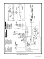
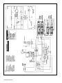
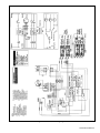
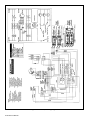
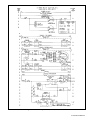
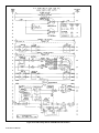
E2 Series
Electric Furnaces
Service Manual
Table of Contents
Electrical Requirements......................................................................... 10
Codes, Specifications Requirements ............................................................................ 10
Connection Supply Service Wires ................................................................................ 10
Furnace Sequence of Operation .......................................................... 5
Air Circulator Motor ....................................................................................................... 9
Air Circulation Switch .................................................................................................... 8
Heating Elements ......................................................................................................... 7
Cooling Relay ............................................................................................................... 7
Limit Switches ............................................................................................................... 8
Sequencer .................................................................................................................... 6
General ..................................................................................................... 4
Furnace Specifications ................................................................................................. 4
Model Identification Code ............................................................................................. 4
Serial Number Identification Code ................................................................................ 4
Selecting Blower Speeds ...................................................................... 11
Blower Performance ..................................................................................................... 12
Changing Blower Speeds ............................................................................................. 11
Service Diagrams ................................................................................... 21
4-7 Wire Relay Box for H/P E2EB 020 and 023 Units ................................................... 23
2-Wire Relay Box for A/C E2EH 020 and 023 Units ..................................................... 21
4-7 Wire Relay Box for H/P E2EH 020 and 023 Units................................................... 22
Thermostat Sequence of Operation ..................................................... 12
Wiring Diagrams ..................................................................................... 13
E2EB 010 ..................................................................................................................... 17
E2EB 012 ..................................................................................................................... 18
E2EB 015,017............................................................................................................... 19
E2EB 020, 023 .............................................................................................................. 20
E2EH 010 ..................................................................................................................... 13
E2EH 012 ..................................................................................................................... 14
E2EH 015,017 .............................................................................................................. 15
E2EH 020, 023 ............................................................................................................. 16
3 E2 Service Manual
General
This installations provides an access door for future
installation of an air conditioning/heat pump coil. All E2
series furnaces are A/C, heat pump adaptable. Refer to
table 2 For optional air conditioner/ heat pump
equipment. The E2 series includes two models: E2EH
and E2EB models. The E2EH models are equipped
with a two speed blower and require the addition of a
replay package for the addition of air conditioning or
heat pump. The E2EB furnaces are equipped with a
multi-speed (4-speed) blower, blower relay, and cabinet
insulation.
E2 series electric furnaces are approved for use in
mobile/modular homes. The E2 series furnaces are
approved for downflow and upflow installations as free
standing units, or for alcove installations. All furnaces
models are approved for “zero” inch clearance from
combustible materials. For downflow alcove
installations a grille with frame may be attached to the
top of the furnace and all paneling and trim flushed to
it.
MODEL IDENTIFICATION CODE
E 2 EB - 010 H - A
Options
A -A/C Ready
Product Type
E -Electric Furnace
Electrical Code
H - 240-1-60
Generation
2 - Second Series
Primary Capacity
010 - 10 kw
012 - 12 kw
015 - 15 kw
017 - 17 kw
020 - 20 kw
023 - 23 kw
Product Identifier
EH - Heat Only
EB - A/C Blower Equipped
SERIAL NUMBER IDENTIFICATION CODE
E
2
E
01234
9705
Electric
Production Code
Month
Design Series
Manufacured Housing
Year
Electric Furnace Models
E2EH
E2EB
010H
012H
015H
017H
020H
023H
010H
012H
015H
017H
020H
023H
Rated Heating Output, Btuh (see note1) 35,000
41,000
53,000
57,000
70,000
75,000
35,000
41,000
53,000
57,000
70,000
75,000
12.0
15.4
16.6
20.4
22.0
10.4
12.0
15.4
16.6
20.4
22.0
Watts (Total kw, Heating Elements and
Blower)
10.4
Supply Voltage
240/208 Volts/60Hz/1-Phase
Heating Elements, No.(Total kw) 2 (10.0) 2 (11.6) 3 (15.0) 3 (16.2) 4 (20.0) 4 (21.6) 2 (10.0) 2 (11.6) 3 (15.0) 3 (16.2) 4 (20.0) 4 (21.6)
Blower:
Wheel Size
Motor Speeds, H.P. Rating, Amps
Test ESP, in. w.c. Max
Optional Cooling Available with factory
installed blower
Optional Heat Pump Available with
factory installed blower
Air Filter (Standard)
Furnace Dimensions
10.5" Dia., 8" Wide
10.5" Dia., 8" Wide
2 Speed, 1/5 Hp, 2.0 Amps
4 Speed, 1/3 Hp, 2.9 Amps
0.3
2.0 - 3.0 ton (see note 3)
2.0 - 3.0 ton (see note 3)
n/a (see note 3)
2.0 - 4.0 ton (see note 4)
2.0 - 4.0 ton (see note 4)
16" x 20" x 1" (nominal)
Width - 20" (508 mm) Height - 29" (737 mm) ( see note 2)
Depth - 24-1/2" (623 mm)
1. Heating output rated at listed voltage. For outputs at voltages other than 240V, multiply Btuh rating by the following factors: x 0.92 (230V), x 0.84 (220V), x 0.75 (208V)
2. Height is 56" with return air grille installed, 58" with coil cabinet and 72" with coil cabinet and upflow stand.
3. The factory installed blower for the EH models can be replaced with a multi-speed blower allowing the units to accept up to 4 or 5 tons of air conditioning or heat pump.
4. The factory installed blower for the EB models can be replaced with a multi-speed blower allowing the units to accept up to 5 tons of air conditioning or heat pump.
Table 1. Unit Specifications
4 E2 Service Manual
8
Item
Number
(See Fig. 1)
1
2
3
4
5
6
7
8
7
Description
4-Speed Blower
4 Ton - See Notes: 1 & 5
5 Ton - See Note: 1
A.C./H.P. Relay Control Box
(not req’d on E2EB models)
See Note: 1
Cabinet Insulation Kit
See Notes: 1 & 5
"A"-Coil Conversion Kit
See Note: 2
Coil Cabinet
See Note: 3
Upflow Stand
See Note: 4
A/C and H/P Indoor Coils
27” (686 mm)
4
1
2
29” (737 mm)
3
23 3/4”
(603 m
m)
Return Air Grille and Frame
Assembly
20”
)
(508 mm
20”
Cabinet
Insulation
(50
8m
m)
Notes:
1) For A/C and H/P use.
2) Includes coil filters.
3) For upflow or downflow installations.
4) For upflow A/C or H/P installations (includes
one filter; use filter from furnace to complete
filtering system in this accessory).
5) Standard in EB models.
29” (737 mm)
Table 2. Optional Air Conditioning and
Heat Pump Equipment
/4”
23 3 m)
3m
(60
5 Coil Cabinet
Sequence of operation
With the circuit breakers in the on position and the
blower switch in the auto position. One half of the
control heating element and motor electrical circuit is
activated. When the contacts close in the wall
thermostat 24 volts is supplied by the 240/24 volt
transformer to the sequencer heater. This heats a bi metal in the sequencer which closes a set of contacts
and completes the circuit to the no.1 element and the
blower motor. As the heater continues to build up heat,
the bi-metal closes the remaining circuits to other
elements, until all elements are on. The “off” cycle is
reverse of the “on” cycle the blower and no.1 element
are first on and the last to be de-energized.
20”
(50
8m
m)
14” (357 mm)
m)
3m
(60
”
4
/
23 3
Filters (one obtained
from furnace)
6 Upflow Stand
NOTE: See Table 2 for descriptions and notes
Figure 1. Optional Accessories
5 E2 Service Manual
Sequencer (Figure 2)
In general all sequencers operate the same way. In
some applications one sequencer may be sufficient
(10 and 12 kw models) in other applications. One two
or more sequencers may be required.
Important: Sequencers should never be mixed. If
different brands of sequencer are used and their timing
may be different.
Testing Sequencer
1. Shut off the power supply to the furnace, there
could be two circuits. Be sure both "A" and "B"
circuits are de-energized.
a. Remove all wires from the sequencer (making
note of wire color and terminal location). The
bi-metal heater portion of the sequencer will be
unmarked and at the bottom, closest to the
mounting plate. The switching portion will be
marked M1 through M8 depending on the
number of switches. Refer to unit wiring
diagram.
b. With an ohmmeter, test for continuity across
the bi-metal heater terminals. There should be
70 to 90 ohms of resistance. If the meter reads
no continuity, the bi-metal heater is open and
must be replaced. The OHMS value should be
70 to 90 across the bi-metal.
Figure 2. Sequencer
c.
With an ohmeter check all switches in the
sequencer. They are labled M1-M2, M3M4...refer to Figure 2. All of the switches should
be open and have no continuity.
2. With all power on to furnace, and thermostat
contacts closed: using a voltmeter (set scale for
220 vac.) On contact terminals of sequencer,
check each set of terminals of sequencer, check
each set individually. If you read voltage, contacts
are open. If you do not read voltage, contacts are
closed. Allow a maximum time (110 seconds) for
heater to close contacts. If any of the contacts
remain open after three minutes the sequencer is
defective and should be replaced.
Indoor Coil
(optional)
Coil Air Filters
(used with indoor coil)
Blower
A/C or H/P Relay Box (optional)
Blower Selector Switch
(next to blower)
Furnace Air Filter
(NOT used with indoor coil
and coil air filters)
Control Panel Cover
(right)
Data Label
Control Panel Cover (left)
Circuit Breakers
6 E2 Service Manual
Refer to unit wiring diagram section for wiring of
sequencer for each model furnace.
Control Transformer (Figure 3)
All E2 furnaces are equipped with a 30 VA, 240/208
vac primary, 24 vac secondary transformer.
The function of the transformer is to supply the 24
volts for the low voltage circuit which activates the
controls. Note: never replace a transformer with one
of less VA rating: however a higher rated transformer
can replace a lower rated unit. Example: unit has 30
VA replacement can be 40 VA.
Checking Transformer
1. Using a voltmeter, test power supply on the primary
leads of the transformer- must be 240 v +/- 10%.
If less than 226 vac switch black and blue primary
leads.
2. Remove wires from the secondary side of the
transformer. Or find the area where the wires
terminate and remove from component.
3. Use the voltmeter check the output of the
transformer, it should read 22 to 28 volts. If not,
Figure 5. Heating Elements in Furnace
then the transformer is nonfunctional and should
be replaced. Observe the transformer there should
be no distortion in shape, oil residue or odor. If any
of these symptoms exist replace the transformer.
Heating Elements (Figures 4 & 5)
The heating elements used are of modular design
consisting of helical-coiled nichrome resistance wire.
An insulated wire formed assembly supports the heating
elements. All elements are rated at 240 volts. Each
element is individually controlled by a switch of the
sequencing system and is protected by a limit switch.
The function of the heating element, of course, is to
heat the air passed across them by the blower system.
Figure 3. Transformer
Testing Heating Elements (Ohmmeter)
1. Shut off all electric supply to furnace
2. Remove all wires from terminals of heating coils
3. Using the ohmmeter test from terminal to terminal
of the coil-must show continuity-if not replace
element assembly.
4. Using the ohmmeter test from heating element
terminal to ground wire in the control panel, there
should be no continuity. If there is the coil is
grounded and must be replaced.
Caution: Heating elements must always be replaced
by an identical kW replacement. Substitution by higher
kW’s or elements of a different design may result in
unsafe operation of the furnace. Lower kW rated
elements will reduce output and may result in
unsatisfactory operation of the appliance. Refer to
element rating labels and furnace wiring diagrams.
Figure 4. Heating Element
7 E2 Service Manual
Figure 7. Limits in furnace
The limit device is a safety which can be compared to
a fuse or a breaker in a electrical circuit. The function
of the limit switch is to open the electrical circuit to the
heating elements if over heating should occur. This
could be caused by air circulator failure, dirty filters,
lack of return air, restricted ducts, etc. All limit switches
used are of the automatic reset type. On cool down
they will automatically reset.
Figure 6. Cooling Relay
Cooling Relay (Figure 6)
The E2EB has a factory installed cooling relay. The
cooling relay operates the air circulator at the high
speed when the relay is energized. The relay is
energized by the low voltage circuit by the g terminal
of the thermostat. At the same time it breaks the circuit
to the heating speed of the air circulator. the cooling
relay has one set of normally closed and one set of
normally open contacts.
Testing Cooling Relay
1. Turn off all power supply to furnace.
a. Remove all wires from cooling relay.
b. Using ohmmeter, test from terminal no. 1 to
terminal no.3 the coil should have resistance of
around 76 ohms. If there is no continuity, the
relay has a open coil and must be replaced.
c. Using ohmmeter, test from terminal no.5 to
terminal no. 6 there should be continuity, if no
continuity is shown relay is defective and must
be replaced.
d. Replace wires on terminal no.1 and 3 restore
power supply.
e. Energize relay by positioning the fan switch on
the thermostat to the fan position. The relay
should click.
f. Using ohmmeter, test terminals 2 and 4 there
should be continuity. If no continuity relay is
defective.
g. Turn off all power to furnace, reconnect all
wires to relay and restore power.
Limit switches
A limit switch is a heat sensing device utilizing a bimetal disc to open a set of normally, closed contacts.
8 E2 Service Manual
Testing the Limit Switches
1. Shut off all electric supply to furnace.
2. Allow enough time for limit to cool down ( 5 to 10
minutes)
3. Remove wires from terminals of limit switches.
Note: all limit switches will be located on the
heating element rack face plate with red wires
attached to them.
4. Using the ohmmeter, test from terminal to terminal
continuity must be read. If no continuity is read
after cool down time, switch is defective and should
be replaced.
Caution: Limit switches must always be replaced by
their identical replacement part, i.e. Same setting, style
limits on the E2 series are either single or double pole
type thermo disc. Under no circumstance should a
limit of a higher setting or of a different type be installed.
Replacement with a lower setting limit may result
cycling of the control and insufficient heat output.
Air Circulation Switch
The air circulation switch is a manual rocker type
switch, single pole double throw, the switch when in the
“auto” position, allows the blower to be activated by the
Figure 8. Air Circulation Switch
sequencer. The blower will run during the heating
cycle of the furnace. When the switch is in the “fan”
position the blower will run continuously. See Figure
8 for air circulation switch.
1
Black
2
Red*
3
Yellow
* Yellow on E2EH 015, 017, 020, 023
Figure 9. Fan Switch Shematic
Checking the Air Circulator Selector Switch
To check the air circulator switch shut of all power to the
furnace. Remove wires from air circulator selector
switch terminals. Check continuity of terminals with the
switch in “on” and “auto” position. See Figure 9 for fan
switch schematic.
Capacitor(See Figure 10):
1. Shut off the electrical supply to the unit.
2. Disconnect he electrical leads to the capacitor.
3. Discharge the capacitor using a 1500 ohm resister.
4. Check the capacitor using a capacitor tester.
Blower Motor (See Figure 11):
1. Shut power off to the furnace.
2. Disconnect the electrical motor leads.
3. Using an ohmmeter, check for continuity from each
terminal to the shell of the motor, if there is continuity,
the motor is grounded and should be replaced.
4. Using the ohmmeter, check the resistance across
the motor leads. See diagrams below. Note: the
higher the speed the lower the resistance of the
motor winding.
Air Circulator Motor
The circulator motor and blower wheel combination
move air across the heating elements to supply the
duct system with warm air.
To check the motor, be certain the capacitor is
functional.
Figure 11. Blower
Figure 10. Capacitor
Figure 12. Motor Schematic
9 E2 Service Manual
ELECTRICAL REQUIREMENTS
! WARNING:
To avoid the risk of electrical shock, personal
injury or death, disconnect all electrical power
to the unit before performing any maintenance
or service. The unit may have more than one
electrical power supply.
NOTE: To install single-circuit kit, perform step 5. If
single-circuit kit installation is not necessary, go to
step 6.
5. To install single-circuit kit.
a. Loosen lugs at supply side of circuit breakers.
b. Remove cover from single-circuit kit (if
supplied).
c. Insert metal buss bars of kit into lugs of circuit
breaker.
d. Tighten lugs securely (45 in.-lbs. recommended).
ON
ON
Figure 13. Installation of Optional Single Circuit Adaptor Kit
Circuit Breaker
Bracket
OFF
ON
OFF
60A
ON
Circuit
Breaker Wire
Assemblies
(Factory
Installed)
60A
10 E2 Service Manual
OFF
Connecting Supply Service Wires
1. Remove right-hand control panel (when viewing in
downflow position).
2. Locate power supply hole plugs in side of unit and
in bottom of unit. Remove appropriate plug(s) or
knockout opening applicable to recommended wire
size(s).
3. Install listed cable connector(s) in opening(s). If
metal-sheathed conduit is used for incoming power
line(s), provide an approved metal clamp on conduit
and secure it in entrance knockout.
4. Insert supply service wire(s) through cable
connector(s) and connect wires to circuit breakers
(Figures 13 and 14).
60A
Note: Circuit breakers installed within this unit
are for short-circuit protection of the internal
wiring and to serve as a disconnect. Circuit
breakers installed within this unit DO NOT provide
over-current protection of the supply wiring and
therefore may be sized larger than the branch
circuit protection.
OFF
! IMPORTANT:
60A
Codes, Specifications, and Requirements
The wiring, installation, and electrical hookup of this
furnace must comply with the National Electrical Code 6. Connect service ground wire(s) to grounding lug(s)
(or the Canadian Electrical Code) and all regulations of
provided. One ground is required for each supply
local authorities having jurisdiction. See Table 3 for
circuit used.
minimum circuit ampacity, maximum over-current
protection, and recommended wire size. See the unit
Circuit Breaker
wiring diagram for other wiring details.
Optional Single Circuit
Bracket
Adaptor Kit
Supply-circuit requirements are as follows:
Circuit
Breaker Wire
• -010 model is factory-wired for single-branch supply
Assemblies
(Factory
circuit only.
Installed)
• -012 models are factory-wired for single-branch
supply circuit (single-circuit kit installed). Dualbranch circuit can be used by removing factoryinstalled single-circuit kit (see Figures 13 and 14).
• -015, -017, -020 and -023 models are factory-wired
Supply Service
Wire Connection
for dual-branch supply circuit. Single-branch circuit
With Single Circuit
Adaptor Kit
can be used by installing optional single-circuit kit .
Supply Service
Wire Connection
Without Single
Circuit Adaptor Kit
Figure 14. Installation of Supply Service Wires
! WARNING:
To avoid personal injury or property damage, make
certain that the motor leads cannot come into
contact with non-insulated metal components of
the unit.
Recommended Wire
Sizes*
Model
E2EH/
E2EB-
Supply
Circuit
Max Over-
Min.
75°C Copper
Low-Voltage
Total
Amperes
Current
Rating
Circuit
Ampacity
Wire Size
Ground Size
010
Single
45.5
60
57
6
10
012
Single
52.1
70
65
6
8
"A"
28.0
40
35
8
10
"B"
24.2
30
30
10
10
66.3
90
83
4
8
"A"
45.5
60
57
6
10
"B"
20.8
30
26
10
10
71.3
90
89
3
8
"A"
48.8
60
61
6
10
"B"
22.5
30
28
10
10
87.1
125
109
2
6
"A"
45.5
60
57
6
10
"B"
41.7
60
52
6
10
93.8
125
117
1
6
"A"
45.5
60
57
6
10
"B"
48.3
60
60
6
10
Dual
015
Single
Dual
017
Single
Dual
020
Single
Dual
023
Single
Dual
Thermostat Wire
Size
2-Wire
system max wire
lengths :
24 Ga. = 55’
22 Ga. = 90’
20 Ga. = 140’
18 Ga. = 225’
4 or more-Wire
system max wire
lengths :
24 Ga. = 25’
22 Ga. = 45’
20 Ga. = 70’
18 Ga. = 110’
* All wire sizes for copper conductors only, based on NEC Table 310-16. Equivalent wiring may be used per NEC.
Table 3. Electrical Specifications
Selecting Blower Speed
! IMPORTANT:
! WARNING:
To avoid personal injury or property damage, make
certain that the motor leads cannot come into
contact with non-insulated metal components of
the unit.
See Table 4 for the lowest speed approved for the heating
output of the unit. Since the blower leads connect to the
control box, blower speed selection is accomplished through
use of the proper color-coded blower lead located inside the
control box. The speed(s) set by the factory may be different
from that shown on the wiring diagrams. See the unit control
box for blower speed(s) set at factory.
Plug/Receptical Position Pin 1 Pin 2
Pin 3 Pin 4
2-Speed Blower
Low
4-Speed Blower
Low Med-Lo Med-Hi High
Control Box Blower Lead
High
-
Red Yellow Blue
Minimum approved
speed for 010, 012
and 015 models.
Minimum approved speed for
017, 020 and 023 models.
If a relay box is installed, blower speeds for
heating and cooling are set inside the relay box
(see instructions included with relay box). The
blower speed inside the furnace control box
must be set to low or medium-low. Never change
to a heating speed lower than that shown in
Table 4.
Changing Blower Speed
E2EH: The selected heating blower lead is attached to
terminal 2 of blower selector switch.
a. Remove blower lead from terminal 2.
b. Choose desired speed and install new blower lead onto
terminal 2 of blower selector switch.
-
Black
E2EB: The selected heating blower lead is attached to
terminal 6 on blower relay. The selected cooling blower lead
is attached to terminal 4 on blower relay.
a. Remove heating blower lead from terminal 6 on blower
relay.
b. Choose desired speed and install new blower lead onto
terminal 6 of blower relay for new heating speed.
Table 4. Furnace Blower Speed Data
11 E2 Service Manual
c. Remove cooling blower lead from terminal 4 on blower
relay.
d. Install new blower lead onto terminal 4 of blower relay for
new cooling speed.
See Table 5 for blower performance data.
Standard 2-Speed Blower,
with filter, @ 0.3" ESP
Pin No.
Speed
CFM
#1
Low
840
#2
High
1160
4-Speed Blower, with Coil and
Coil Filters, @ 0.3" ESP
Pin No.
Speed
CFM
#1
Low
880
#2
Med.-Low
1170
#3
Med.-High
1310
#4
High
1460
Table 5. Blower Performance
THERMOSTAT SEQUENCE OF OPERATION
NOTE: If appliance(s) is equipped with time delay
control, the system operation will lag behind the
thermostat.
For Heating
1. Turn on electrical power to appliance.
2. With thermostat cover off, move temperature-setting
lever until right-hand (heating) contacts close. For
CM65A-5ABO, CM65A-5JBO or CM65 with optional
sub-base, set heat/cool switch to “HEAT” and set ventilate switch to “AUTO.” Heating system and air circulator blower should turn on.
3. Check air temperature at supply duct registers.
4. Move temperature-setting lever until right-hand (heating) contacts open. Heating system and air circulator
blower should turn off.
5. Replace thermostat cover.
For Cooling
1. Turn on electrical power to the appliance.
2. With the thermostat cover off, move temperature-setting
lever until left-hand (cooling) contacts close. For CM65A5ABO, CM65A-5JBO or CM65 with optional sub-base,
set heat/cool switch to “COOL” and set ventilate switch
to “AUTO.” Cooling system and air circulator blower
should turn on.
3. Check air temperature at supply duct registers.
4. Move temperature-setting lever until left-hand (cooling)
contacts open. Cooling system and air circulator blower
should turn off.
5. Replace thermostat cover.
For Continuous Air Circulation and Ventilation
NOTE: For CM65, see furnace owner’s manual on independent blower operation. For CM65A-5ABO, CM65A-5JBO or
CM65 with optional sub-base, follow the steps below.
1. Set thermostat heat/cool switch to “OFF” and set ventilate switch to “ON.” Air circulator blower only should turn
on.
2. Set thermostat heat/cool switch to “HEAT.” Air circulator blower should operate continuously with on and off
heat cycles.
3. Set thermostat heat/cool switch to “COOL.” Air circulator blower should operate continuously with on and off
cooling cycles.
For System Shutoff
1. With electrical power to appliance turned on, move
temperature-setting lever to turn on heating or cooling
system.
2. Set ventilate switch to “AUTO” and set heat/cool switch
to “OFF.” All system operations should turn off.
12 E2 Service Manual
Figure 15. E2EH 010 Wiring Diagram
13 E2 Service Manual
Figure 16. E2EH 012 Wiring Diagram
14 E2 Service Manual
Figure 17. E2EH 015, 017 Wiring Diagram
15 E2 Service Manual
Figure 18. E2EH 020, 023 Wiring Diagram
16 E2 Service Manual
Figure 19. E2EB 010 Wiring Diagrams
17 E2 Service Manual
Figure 20. E2EB 012 Wiring Diagram
18 E2 Service Manual
Figure 21. E2EB 015, 017 Wiring Diagram
19 E2 Service Manual
Figure 22. E2EB 020, 023 Wiring Diagram
20 E2 Service Manual
Figure 23.Two-Wire Relay Box for A/C E2EH 020 and 023 Units
21 E2 Service Manual
Figure 24. 4-7-Wire Relay Box for H/P E2EH 020 and 023 Units
22 E2 Service Manual
Figure 25. 4-7-Wire Relay Box for H/P E2EB 020 and 023 Units (Part 1)
23 E2 Service Manual
Figure 26. 4-7-Wire Relay Box for H/P E2EB 020 and 023 Units (Part 2)
24 E2 Service Manual
NOTES: ________________________________________________________
_______________________________________________________________
_______________________________________________________________
_______________________________________________________________
_______________________________________________________________
_______________________________________________________________
_______________________________________________________________
_______________________________________________________________
_______________________________________________________________
_______________________________________________________________
_______________________________________________________________
_______________________________________________________________
_______________________________________________________________
_______________________________________________________________
_______________________________________________________________
_______________________________________________________________
_______________________________________________________________
_______________________________________________________________
_______________________________________________________________
_______________________________________________________________
_______________________________________________________________
_______________________________________________________________
_______________________________________________________________
_______________________________________________________________
_______________________________________________________________
_______________________________________________________________
26 E2 Service Manual
R
R
359A-1097
Specifications and illustrations subject to change without notice and
without incurring obligations. Printed in U.S.A. (10/97)
St. Louis, MO