1
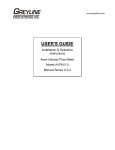
USER’S GUIDE
Installation & Operation
Instructions
Tank Farm Transmitter
Model TFT32
Series 2.0
Ultrasonic Sensor Input (-A-)
TFT32 Tank Farm Transmitter
INDEX:
Item
Page
Bench Test and Connections
2
5
Calibration System
Calibration Menu
6
7
Calibration Units Selection
Min Range Max Range Calibration
8
9
10
Relay Calibration
Damping
Transmitter / Tank Address
Baud Rate _________________________________________________
Output Simulation
Store/Save Calibration
Temperature Indication
Communication Protocol _____________________________________
Enclosure Installation
Sensor Mounting
Error/Warning Messages
Troubleshooting
Fuse Replacement
10
11
11
11
12
13
15
16
19
20
22
23
Applications Hotline
Product Return Procedure
23
24
25
Warranty
Appendix A (Options)
Appendix B (Applications Background)
32
33
34
Conversion Tables
Specifications
IMPORTANT NOTE: This instrument is manufactured and calibrated to meet product
specifications. Please read this manual carefully before installation and operation. Any
unauthorized repairs or modifications may result in a suspension of the warranty.
Available in Adobe Acrobat pdf format
Page 1
TFT32 Tank Farm Transmitter
QUICK BENCH TEST:
Connect the Ultrasonic Sensor as shown below, then apply Power. When properly connected a soft
clicking can be heard from the sensor and figures will show on the LCD display. Test operation of the
TFT32 by holding the sensor steadily and aiming at a flat, stable target 12 to 28” (305 to 711 mm) away
from the end of the sensor. Allow a few seconds for the TFT32 to lock onto the target before displaying
its distance. The TFT32 will now display range in inches or cm.
CONNECTIONS (ULTRASONIC):
POWER INPUT: The standard model requires DC power input between 15 to 24VDC with current
consumption of 120mA maximum. Power GND must be connected to a good “earth” ground for surge
protection.
RS485 NETWORK: Connections from the RS485 network (other TFT32’s and the PC computer) are:
Data -(D*), Data +(D) and signal/shield ground (S.G.)
IMPORTANT NOTE: To comply with CSA/NRTL standards, power input and relay connection wires
must have a water tight fitting conduit entry to the instrument enclosure.
S.G
RS485
(1 AMP)
D
RELAY
D
–
GND
+
24VDC
*
14 AWG MAX
SENSOR
RG62AU
COAXIAL
TO SENSOR
CONNECT
TO RS485
NETWORK
CABLE
IMPORTANT:
MUST CONNECT TO A
GOOD GROUND (<1 Ohm)
WITH 14 AWG CONDUCTOR
4-CONDUCTOR SHIELDED
18 AWG RECOMMENDED
TO RS485
NETWORK
Page 2
TFT32 Tank Farm Transmitter
LOCAL NETWORK CONNECTIONS
LAST (FURTHEST) TFT IN THE NETWORK
120 ohm
TERMINATOR
(supplied)
DO NOT
CONNECT SHIELD
MORE
TFT'S
MORE
TFT'S
PS150 POWER SUPPLY
RS485
DB9F
RS232
485OI9TB-24V
To
RS232
Port
D–
D+
DO NOT
CONNECT
SHIELD
S+ V+ V+ V+ V- V- V- S-
GND
24V
D*
D
24V+
24VSHIELD
RS485/232
CONVERTER
Page 3
115VAC
TFT32 Tank Farm Transmitter
DIAL-UP LOCATION CONNECTIONS
LAST (FURTHEST) TFT IN THE NETWORK
120 ohm
TERMINATOR
(supplied)
DO NOT
CONNECT SHIELD
MORE
TFT'S
MORE
TFT'S
PS150 POWER SUPPLY
485OI9TB-24V
NULL
MODEM
RS485
DB9F
RS232
DB9M
DB25M
MODEM
D–
D+
DO NOT
CONNECT
SHIELD
S+ V+ V+ V+ V- V- V- S-
GND
24V
D*
D
24V+
24VSHIELD
RS485/232
CONVERTER
115VAC
Page 4
TFT32 Tank Farm Transmitter
KEYPAD SYSTEM
The TFT32 has a simple 2-key calibration system. Operating and calibration modes are shown on the 4
digit display. The keys are used to calibrate the TFT32, and to view operating mode and functions. If the
keys are not used for 10 minutes, the TFT32 will automatically go to NORMAL MODE. Except in
OUTPUT SIMULATION mode, the Relay and RS485 serial output are not affected by use of the keys
until your calibration is stored
4-DIGIT LCD DISPLAY
POWER
CONNECTION
+–
GND
CALIBRATION KEYS
SENSOR
CONNECTION
RS485 NETWORK
CONNECTION
.
MENU - FLOW CHART
The following diagram shows the TFT32 Menu system. Arrows show the directions to leave a box.
Pressing a corresponding key will move to the next box in the direction shown. Numeric values are
changed by pressing and holding the or keys.
At the bottom of Menu is a YES? prompt. To store the calibration values permanently (even through
power failure), press the key. If the key is pressed from the YES? prompt no changes will be
stored and the system will return to NORMAL mode.
Page 5
TFT32 Tank Farm Transmitter
TFT32 CALIBRATION MENU
ULTRASONIC SENSOR INPUT
TEMPERATURE
Displays Temperature (at Sensor) in °C
RANGE DISPLAY
Displays distance from Sensor to Target
(Does not affect RS-485 output or Relay)
RANGE CM
FLASHING
NORMAL MODE
LEVEL CM
CALIBRATION UNITS SELECTION
Press to select inches, cm or percent
PERCENT INCHES CM
CM
CM
3, 5, 6
RANGE CALIBRATION
RAN1 = Min Range RAN2 = Max Range
Wait for the numeric value then press or to increase or
decrease.
Value displayed is distance from the Sensor in inches or cm.
Wait for RAN1 or RAN2 and press for next Function
RELAY OPERATION CHOICE.
Press to select:
3 = Echo Loss Only
1 = Level Alarm
4 = Temperature Alarm
2 = Level + Echo Loss
5 = Always OFF
6 = Always ON
1, 2, 4
PERCENT
RELAY SET POINTS
Wait for numeric value and press and to adjust Set Points
(in percentage of Span or °C)
PERCENT
DAMPING (0-15 secs)
Press to adjust
Press to select "Y" (Yes) only when the instrument is
equipped with an optional Intrinsic Safety Barrier for
sensor mounting in hazardous locations. This setting
compensates for the electrical characteristics of an
Intrinsic Safety Barrier.
Sb=n
TRANSMITTER/TANK ADDRESS
Press to select 1-32
SERIAL OUTPUT BAUD RATE
Press to select
19 = 19200
9 = 9600
PERCENT
4 = 4800
2 = 2400
OUTPUT SIMULATION
Wait for numeric value and press and to increase or
decrease Simulated Output (Automatically returns to NORMAL
mode in 10 minutes)
YES
NO
STORE YES?
Press to store Calibration (displays -C.S-)
Press Calibration Not Stored
Page 6
TFT32 Tank Farm Transmitter
NORMAL MODE
CALIBRATION UNITS SELECTION
Press from NORMAL mode, Display will show:
Echo light keeps flashing
to show that the instrument
is still operating
PERCENT
RANGE
CALIBRATION
INCHES
CM
INCHES
PERCENT
CM
Page 7
TFT32 Tank Farm Transmitter
rAn1 = MIN RANGE CALIBRATION
Calibrate the distance between the sensor and maximum level.
and
The Display will alternate between
CM
1524
1523
1522
rAn 2
every 3 seconds.
30.6
30.7
30.8
MAXIMUM VALUES: 1524 cm / 600.0
inches
rAn2 = MAX RANGE CALIBRATION
Wait for rAn1 and press to display rAn2. Now follow the same procedure to calibrate the distance
from the Sensor to zero level (Max. Range).
LEVEL
(Inventory)
rAn1
(Min Range)
Max Level
rAn2
(Max Range)
Zero Level
Page 8
TFT32 Tank Farm Transmitter
RELAY OPERATION CHOICE
The TFT32’s Signal Relay can be configured to operate as:
ROC1 = Level Alarm
ROC2 = Level + Echo Loss Alarm
ROC3 = Echo Loss Alarm only
ROC4 = Temperature Alarm (measured at the Sensor)
ROC5 = OFF (de-energized) at all times
ROC6 = ON (energized) at all times
roc = 3,5,6 roc = 1,2,4
ROC2
ROC3
ROC4
Press to select the ROC.
RELAY CALIBRATION
ROC1 (Level Alarm)
ROC2 (Level + Echo Loss Alarm) - Relay will be energized when the Relay ON set point is
reached.
or if the echo is lost (no echoes for more than 20 seconds).
ROC4 (Temperature Alarm)
-
Minimum Set Point -40°C (= -40°F)
Maximum Set Point 100°C (= 212°F)
NOTE: The Set Points are displayed in percentage of span (LEVEL). Two different Set Points (r ON
and rOFF) allows a Relay “deadband” for Pump Control and to avoid Relay chatter.
Page 9
TFT32 Tank Farm Transmitter
SENSOR
Example of Relay Calibration
Span (Max Level) = 184 inches
RON in percent =150/184 = 81.5%
ROFF in percent = 30/184 = 16.3%
rAn1 = 16"
R ON
150"
SPAN = 184"
R OFF
30"
rAn2 = 200"
DAMPING
Normal Setting: DP10
Fast Response (up to ½ inch /13 mm level
change per second): DP5 or less
DP11
DP12
15 SECS.
MAXIMUM
Slow Response (turbulence) DP15
NOTE: Damping Time (in seconds) is the response time to indicate a new target. Longer Damping
Times also reject false targets like agitators, splashing etc.
TRANSMITTER/TANK ADDRESS
Select transmitter address 1 to 32 taking into consideration
the following:
1) Each transmitter must have a different address.
2) The address number is also the tank position on the
page when running the TFS PC software.
Page 10
TFT32 Tank Farm Transmitter
BAUD RATE
Select the highest Baud Rate
whenever possible. All Transmitters
connected to the network must
have the same Baud Rate.
OUTPUT SIMULATION MODE
The Output Simulation controls the RS485 serial output, digital display and signal relay. Use it to test
Transmitter Communication to the remote PC running TFS software and to test Relay set-points.
Simulation values are in percentage of Span.
TO STORE (SAVE) CALIBRATION
Press to Store calibration (TFT will display -C.S-).
Calibration is stored in non-volatile memory (even through power interruptions).
Press to return to NORMAL mode without storing any changes.
Page 11
TFT32 Tank Farm Transmitter
RANGE DISPLAY
From Normal Mode press Displays distance from the Sensor to Target.
Use to check measurements during calibration.
(RANGE and UNITS flash.)
TEMPERATURE DISPLAY
Displays temperature in degrees Centigrade
measured at the Sensor.
TEMPERATURE LOG
Displays maximum temperature in degrees
Centigrade measured at the Sensor.
From normal Temperature display, Press then .
Page 12
TFT32 Tank Farm Transmitter
TFT32 COMMUNICATION PROTOCOL
Greyline TFS Tank Farm Supervisor software manages communications with TFT32 Transmitters
automatically. The following Communication Protocol information is supplied for programmers who
are not using the Greyline TFS Tank Farm Supervisor program. Programmers can create their own
drivers to address TFT32 Transmitters through other software programs on PC computers or PLC’s.
The TFT32 uses an ASCII format command/response protocol. The TFT transmits an answer only when
polled with a valid command and address. The Host computer always initiates the command/response
sequence.
Example of command/response sequence:
Command: #%1RA<CR>
Response: *%1RA+959.3000210AA<CR>
COMMAND STRUCTURE:
#% 1 RA <CR>
COMMAND
PROMPT
FOR TFT32
COMMAND
(MUST BE
CAPITAL
LETTERS)
TANK/TFT
ADDRESS
1-9 = 1-9
A-W = 10-32
CARRIAGE
RETURN
RESPONSE STRUCTURE:
*%1RA +959.3 0 0 021 0 AA <CR>
RESPONSE
PROMPT
TFT DATA
(SEE TEXT)
MODE
0=LEVEL
UNITS
0 = cm
Page 13
RELAY
STATUS
0=OFF
1=ON
TEMP
IN °C
-99 to 999
CHECKSUM
IN HEX
CARRIAGE
RETURN
TFT32 Tank Farm Transmitter
COMMAND SET
COMMAND
DEFINITION
RA
Read all
parameters
Read Span
(Max Level)
New Baud Rate
xx = 00 = 38400
01 = 19200
02 = 9600
03 = 4800
04 = 2400
Remote Reset
Broadcast Reset
RS
NBxx
RR
!RR
COMMAND MESSAGE
(Address 1)
#%1RA<CR>
*%1RA+959.3000210AA<CR>
#%1RS<CR>
*%1RS+999.9000210BF<CR>
#%1NBxx<CR>
(TFT will change to new
Baud Rate only after
reset)
*%1NB02
#%1RR<CR>
#%!RR<CR>
(All units in the Network
will reset)
*1RR
(No Response)
TFT RESPONSE:
TFT Data:
Valid analog Data Range is + 000.0 to + 6550.
Values with (-) sign represent error messages
- 100.0 = “Not Ready Please Wait”
- 101.0 = “Echo Loss”
- 102.0 = “Sensor Short”
- 103.0 = “Losing Echo”
- 104.0 = “Sensor Open”
- 105.0 = “Bad/Weak Echo”
- 106.0 = “No Echo in Range”
- 107.0 = “Echo in Deadband”
Units and mode: Always cm and Level.
Page 14
TYPICAL RESPONSE
TFT32 Tank Farm Transmitter
ENCLOSURE INSTALLATION
Locate the enclosure within 500 ft (150 m) of the ultrasonic sensor. It can be wall mounted with four
mounting screws (supplied) or panel mounted with Option PM Panel Mounting Kit from Greyline
Instruments. Avoid mounting the enclosure in direct sunlight to protect the electronics from damage due
to overheating and condensation. Seal conduit entries to prevent moisture from entering enclosure.
NEMA4X (IP67) WITH CLEAR COVER
ENCLOSURE
MOUNTING
HOLES
ENCLOSURE
END VIEW
1. Remove enclosure cover.
2. Insert #6 screws through the four enclosure mounting holes
to secure enclosure to wall or mounting stand.
3. Replace Cover
An additional conduit hole can be cut in the end of the enclosure
if required. Use a hole saw or Greenlee-type hole cutter to cut
the required holes.
Note:
1. This non-metallic enclosure does not automatically provide grounding between conduit connections.
Grounding must be provided as part of the installation. Ground in accordance with the requirements
of the National Electrical Code. System grounding is provided by connecting grounding wires from
all conduit entries to the steel mounting plate or another point which provides continuity.
2. Water tight “O” ring seals must be used if cable strain-reliefs are used.
Page 15
TFT32 Tank Farm Transmitter
SENSOR MOUNTING LOCATION
SENSOR MOUNTING
Each sensor is equipped with a ¾ inch “isolation coupling” which MUST be used in your installation. A
threaded nipple or length of conduit may be used to position the sensor at the desired height.
The sensor should be hand-tightened (like a light bulb) by turning the sensor stem only. DO NOT use a
wrench and do not over tighten. DO NOT clamp the sensor below the isolation coupling.
The standard PZ32T Sensor must be mounted 12" / 30.48 cm or more above the maximum liquid level.
(Optional PZ12 sensor must be 8" / 20.3 cm above maximum level and optional PZ52T sensor must be
24" / 610 mm above maximum level.)
Page 16
TFT32 Tank Farm Transmitter
SENSOR MOUNTING
Notes:
1. Use the ¾" NPT "Isolation Coupling"
supplied and hand tighten only. Do
not clamp sensor body or stem.
2. Locate the sensor 1 ft (30 cm) from
the sidewall or obstruction for every
10 ft (3 m) depth.
3. Do not mount in direct sunlight.
4. Extend sensor cable up to 500 ft
(150 m) with RG62AU coaxial only.
FLANGE MOUNT
4" OR 6" BLIND FLANGE
TAPPED ¾" NPT
JUNCTION
BOX
(OPTION JB)
¾" NPT
NIPPLE
DO NOT
CLAMP IN
THIS AREA
CROSS BAR MOUNT
FLEXIBLE
CONDUIT
ISOLATION
COUPLING
(SUPPLIED)
MUST BE
USED
CLAMP
CONDUIT MOUNT
3/4"
CONDUIT
DO NOT
CLAMP IN
THIS AREA
ISOLATION
COUPLING
(SUPPLIED)
MUST BE
USED
3/4"
CONDUIT
STAND PIPE MOUNT
ISOLATION
COUPLING
(SUPPLIED)
MUST BE
USED
DO NOT
CLAMP IN
THIS AREA
STANDPIPE LENGTH
AS SHORT AS POSSIBLE
STANDPIPE DIAMETER
AS LARGE AS POSSIBLE
TYPICAL STANDPIPE:
4” / 100 mm DIAMETER
12” / 300 mm LENGTH
ANGLE MOUNT
NARROW DIAMETER
STANDPIPES (<4” / 100 mm)
MAY AFFECT ACCURACY
OF READING
3/4" NPT
NIPPLE
SMOOTH
DO NOT
CLAMP IN
THIS AREA
GRIND OR FILE
PIPE EDGE
Page 17
ISOLATION
COUPLING
(SUPPLIED)
MUST BE
USED
TFT32 Tank Farm Transmitter
BAD
SOLIDS AND POWDERS
SENSOR MOUNTED
AWAY FROM MATERIAL
PATH. COARSE SOLIDS
WILL USUALLY RETURN
AN ECHO EVEN IF AT
AN ANGLE
FINE POWDERS
MAY NEED SENSOR
TILTED NORMAL TO
SURFACE TO OBTAIN
GOOD ECHOES
Page 18
GOOD
TFT32 Tank Farm Transmitter
ERROR/WARNING MESSAGES
Instrument has detected Sensor connections/cable open.
Instrument has detected Sensor connections/cable short.
The dot before the C in temperature reading indicates
temperature compensation fault. Check sensor connections.
No valid echoes for 10 seconds.
No valid echoes for 20 seconds. See Troubleshooting (F).
or
or
ECHO INDICATOR
INTERMITTANT
Indicates that echoes from the target are
weak or liquid surface is highly turbulent.
See Troubleshooting (A,C,F)
Illegal Span. Distance between rAn1 and rAn2 must be
greater than 2"(5cm). Also distance for rAn2 (Max Range)
must be greater than rAn1 (Min range).
Indicates that the target is above the calibrated
maximum level (too close to the Sensor).
Over Range indicates target is further than the calibrated Maximum Range.
Indicates that the TFT32 has experienced electrical interference strong enough to corrupt
the memory. The TFT32 must be reset and recalibrated.
Reset Procedure 1: Reset will clear all memory. TFT32 will need recalibration after this
procedure: Press and Hold and until the TFT32 displays - - - -.
XX
Always displayed at power-up (x.x indicates Software version).
Otherwise indicates instrument has reset automatically. See Troubleshooting (C,D,E).
Page 19
TFT32 Tank Farm Transmitter
FIELD TROUBLESHOOTING
SYMPTOMS
CHECK
Level Display
- full scale
- zero
- erratic - random
- higher than actual
- fluctuating
A
B
C
D
E
ECHO LOSS prompt - flashing
Calibration Non-Linear
EEEE - memory corruption
F
H
I
SYMPTOMS
FAULTS
Unit “See’s Wrong Target Due To:
A,C,D,F
- sensor not aimed correctly
A,D,F
- dust/dirt buildup on sensor
A,D,F
- condensation on sensor
A,D
D,E
C
SOLUTIONS
- sensor mounting stand pipe
- too long/ - too narrow
- dirty/ - gasket intruding
- agitator, strong turbulence
- material filling through sensor beam
- Clean carefully (do not scratch sensor face)
- Lower sensor
- insulate sensor mounting location
- increase MinRg (CALIBRATION menu)
by 1-3” / 2.5-7.5 cm
- wipe sensor face and body with Rain-X
- Lower Sensor below stand pipe intrusion
- Increase Damping
- Increase Damping
Unit Picks-Up Acoustic Interference Due To:
A,C
- noise from high pressure fill
A,D
- sensor coupling over tightened
A,D
- sensor coupling not used
C
- other ultrasonic sensor in close
proximity
- Install submerged fill pipe
- Hand tighten only (like a light bulb)
- Use isolation coupling supplied
- Separate Sensors
Electrical Interference:
C
- Sensor cable connections reversed
C,D
- through Sensor cable
C
- Sensor cable and/or junction not
insulated
C,D
- through RS485 network cable
- Use properly grounded metal conduit
- Use metal Junction Box
Page 20
- Use shielded twisted pair
TFT32 Tank Farm Transmitter
C,D
C,D,E
I
I
- wiring or installation close to
variable speed drive or inverter
- AC/Chassis Ground missing on
instrument power connections
- Relay sparking produces EMI
interference
- Instrument installed in the same
panel with high voltage/large motor
controls
Wiring Problems Due to Sensor Cable:
C,F
- open circuit
- short circuit
F
C
- too long (max. 500 ft, 150 m)
- bundled/run in conduit with power
cable
- Sensor ground shorted to
conduit/enclosure
- extended with wrong type of wire
- close to high voltage/large motors
A
C
- Use snubber across secondary Relay
contacts
Do not exceed 1 ampere load
- relocate or use metal enclosure
- check connections/continuity (5K Ohms
max.)
- check connections/continuity (5K Ohms
min.)
F
C
- Follow VSD manufacturer’s instructions for
Drive grounding wiring and shielding
- Install adequate Ground
Non-Linearity Due To:
H
- Vapour
B,H
- zero not set accurately
H
- full scale not set accurately
- insulate
- Use only RG62AU coaxial
- calibrate in-situ
- recalibrate
- Note: Minimum Range must be ≥ 12”
(30.5cm)
Page 21
TFT32 Tank Farm Transmitter
FUSE REPLACEMENT
1.
2.
3.
4.
5.
TFT32
Tank Farm Transmitter
Disconnect Power
Remove 2 top screws
Pull and flip chassis
Remove 1 amp fuse with long nose pliers
Install new fuse (Replacement Greyline
Part #740-5068)
1 AMP
Fuse
Page 22
TFT32 Tank Farm Transmitter
APPLICATIONS HOTLINE
For applications assistance, advice or information on any Greyline Instrument contact your Sales
Representative, write to Greyline or phone the Applications Hotline below:
United States:
Canada:
Toll Free:
Email:
Web Site:
Tel: 315-788-9500 Fax: 315-764-0419
Tel: 613-938-8956 Fax: 613-938-4857
888-473-9546
[email protected]
www.greyline.com
Greyline Instruments Inc.
Canada
16456 Sixsmith Drive
Long Sault, Ont. K0C 1P0
USA:
407 County Route 46
Massena, NY 13662
PRODUCT RETURN PROCEDURE
Instruments may be returned to Greyline for service or warranty repair. Before shipping a product to the
factory please contact Greyline by telephone or Fax to obtain an RMA number (Returned Merchandise
Authorization). This ensures fast service and correct billing or credit.
When you contact Greyline please have the following information available:
1.
2.
3.
4.
5.
Model number / Software Version
Serial number
Date of Purchase
Reason for return (description of fault or modification required)
Your name, company name, address and phone number
After obtaining an RMA number please ship the product to the appropriate address below:
Canadian and International
Customers:
USA
Customers:
Greyline Instruments Inc.
16456 Sixsmith Drive
Long Sault, Ont. K0C 1P0
Greyline Instruments Inc.
407 County Route 46
Massena, NY 13662
RMA#
RMA#
Page 23
TFT32 Tank Farm Transmitter
Limited Warranty
_____________________________
Greyline Instruments warrants, to the original purchaser, its
products to be free from defects in material and workmanship for a
period of one year from date of invoice. Greyline will replace or
repair, free of charge, any Greyline product if it has been proven
to be defective within the warranty period. This warranty does not
cover any expenses incurred in the removal and re-installation of
the product.
If a product manufactured by Greyline should prove defective
within the first year, return it freight prepaid to Greyline
Instruments along with a copy of your invoice.
This warranty does not cover damages due to improper installation
or handling, acts of nature, or unauthorized service. Modifications
to or tampering with any part shall void this warranty. This
warranty does not cover any equipment used in connection with
the product or consequential damages due to a defect in the
product.
All implied warranties are limited to the duration of this warranty.
This is the complete warranty by Greyline and no other warranty is
valid against Greyline. Some states do not allow limitations on
how long an implied warranty lasts or limitation of incidental or
consequential damages, so the above limitations or exclusions may
not apply to you.
This warranty gives you specific legal rights, and you may also
have other rights which vary from state to state.
Page 24
TFT32 Tank Farm Transmitter
APPENDIX A - OPTIONS and ACCESSORIES
XC
JB
ISB
12VDC
PM2
PS150
485OICR
- Extra Sensor Cable up to 500 ft (152 m) length
- Sensor Cable Junction Box
- Instrinsic Safety Barrier for Sensor and Cable installation in hazardous-rated
locations (factory-installed option/larger enclosure used)
- 12VDC Power Input (factory-installed option)
- Enclosure Panel Mount
- Network Power Supply
- RS232/485 Converter
EXTRA SENSOR CABLE
(ACCESSORY XC)
Each Greyline TFT32 includes 25 ft. (7.6 m) or 50 ft. (15 m) continuous RG62AU coaxial Sensor
Cable. Additional RG62AU coaxial cable and Cable Junction Box (Option JB) may be spliced and
extended up to 500 ft (152 m) as required during installation. No adjustment is required when the sensor
cable is extended or shortened. Use only RG62AU (or RG62U) coaxial cable which is available from
Greyline Instruments or your local distributor. Nominal impedance of RG62AU cable is 93 ohms.
Extended sensor cable must be installed in metal conduit to prevent interference. Do not use BNC
coaxial connectors (TV cable type). Recommended installation with a metal junction box is illustrated
below:
METAL BOX
TO
SENSOR
CORE
CORE
METAL CONDUIT
SENSOR CABLE
25 ft (7.6m)
RG62AU COAXIAL
METAL CONDUIT
SHIELD
SHIELD
TERMINAL BLOCK
SENSOR CABLE JUNCTION BOX
(ACCESSORY JB)
Page 25
EXTENDED SENSOR
CABLE TO
ELECTRONICS
ENCLOSURE
- MAX. 500 ft (152M)
RG62AU COAXIAL
TFT32 Tank Farm Transmitter
SENSOR INTRINSIC SAFETY - OPTION ISB
FUSE
Mounting
6.18“
157mm
Class I, Groups C,D
Class II, Groups E,F and G
Class III
TFT32
TANK FARM TRANSMITTER
Intrinsic Safety Barriers must be ordered with the Greyline
instrument and are supplied mounted in the Greyline instrument
enclosure. A larger enclosure is used.
2.95“
75mm
END
VIEW
ELECTRONICS ENCLOSURE
CONNECTIONS (Stahl Model 9001/02-133-150-10)
NON-HAZARDOUS LOCATION
FUSE
SEE
NOTE
SENSOR
REPLACEMENT FUSE ASSEMBLY
ORDER PART NO. ISB-011239
(160mA)
Page 26
SHIELD (GREEN)
TDR (WHITE)
NOTE:
BARRIER-EQUIPPED UNITS ARE
FACTORY-WIRED WITH GROUND
THROUGH THE INSTRUMENT
CHASSIS. POWER INPUT
GROUND MUST BE CONNECTED
TO A GOOD GROUND (<1 OHM)
WITH A 12AWG CONDUCTOR
INTRINSIC
SAFETY BARRIER
GREYLINE
INSTRUMENT
HAZARDOUS LOCATION
CLASS I, GROUPS C,D
CLASS II, GROUPS E,F,G
CLASS III
6.89“
175mm
6.89“
175mm
Replacement barrier fuses (Part No. ISB-011239 may be purchased
separately.
Instrinsic Safety Barrier Specifications: Certified, rated 13.8V
max, 95ohms min (Stahl Model 9001/02-133-150-10)
ISB INTRINSIC SAFETY BARRIER
Mounting
6.18“
577mm
When connected through an Intrinsic Safety Barrier, the Greyline
PZ32T-A and PZ32TE-A and PZ52T sensors are CSA certified for
installation in a hazardous location rated:
TFT32 Tank Farm Transmitter
CONNECTIONS - OPTIONAL 115VAC or 230VAC Power Input
GROUND
LINE
NEUTRAL
GND
S.G
RS485
(1 AMP)
D
RELAY
D
OPTIONAL 115VAC 50/60Hz, or
OPTIONAL 230VAC 50/60Hz
*
14 AWG MAX
SENSOR
RG62AU
COAXIAL
TO SENSOR
CONNECT
TO RS485
NETWORK
CABLE
IMPORTANT:
MUST CONNECT TO A
GOOD GROUND (<1 Ohm)
WITH 14 AWG CONDUCTOR
Page 27
2-CONDUCTOR SHIELDED
18 AWG RECOMMENDED
TO RS485
NETWORK
TFT32 Tank Farm Transmitter
6.43"
163.3 mm
INSTRUCTIONS
Mark Panel using Flange
as a Template.
Cut Panel outside the line.
5-3/16"
132 mm
7-3/16"
182 mm
8.40"
213.4 mm
HOLE CENTRES
5.4" / 137.2 mm
P
A
N
E
L
C
U
T
-
O
U
1.75"
44.45 mm
T
Z-BRACKET
QTY 2 INCLUDED WITH
MOUNTING SCREWS
HOLE CENTRES
5.68" / 144.3 mm
FLANGE
QTY 1 INCLUDED
MATERIAL: 0.062 ALUMINUM
FINISH: CLEAR IRIDITE
FLANGE
PANEL
INSTALLATION
INSTRUMENT ENCLOSURE
NEMA4X (IP 67)
Z-BRACKET
Page 28
TFT32 Tank Farm Transmitter
ENCLOSURE SUNSCREEN – OPTION SCR
Do not mount instrument electronics in direct sunlight. Overheating will reduce the life of electronic
components and condensate may form during the heat/cool cycles and cause electrical shorts.
11" / 280 mm
Note:
11"
Exposure to direct sunlight can cause
280 mm
overheating and moisture condensation
which will reduce the operating life of
electronics.
Protect Instruments from direct sunlight
with this iridite finished aluminum sun
screen (Greyline Option SCR).
Seal conduit entries with caulking
compound to further reduce moisture
condensation.
SENSOR SUNSCREEN – OPTION PZS
Page 29
5"
127 mm
TFT32 Tank Farm Transmitter
PS150 POWER SUPPLY
150 Watt Power Supply for TFT32 Tank Farm System
Powers up to 32 Greyline TFT32 Transmitters + 6 RB12 Relay Boards
+
24 VDC
CONDUIT
ENTRY
LOCATION
FUSE
4A, 250V
SIDE VIEW
CONDUIT ENTRY
LOCATION
SPECIFICATIONS PS150 POWER SUPPLY
Power Input: PS150-AI: 90-132VAC, 47-63Hz
PS150-EI: 180-264VAC, 47-63Hz
AC Input Current: PS150-AI: 4A maximum
PS150-EI: 2A maximum
Fuse: 4A, 250V
Operating Temperature: 32 to 122°F (0 to 50°C)
Storage Temperature: -13 to 185°F (-25 to 85°C)
Enclosure: Watertight, dust tight NEMA4X (IP 66) fiberglass
Safety Approvals: UL 1950
CSA 22.2 1402C Level 3
TUV EN 60950 (IEC 950)
Page 30
TFT32 Tank Farm Transmitter
MODEL 485OICR
RS232/RS485 Converter
Converts RS485 signals from Greyline Transmitters to RS232 for connection to a PC Computer or
Modem.
-
DB25 RS232 Connector plugs directly into your computer's
COM port
Optically isolates and protects your computer's RS232 port
Terminal block for RS485 connections
Operates from 2400 up to 38.4 K baud
Terminal connections are provided for RS485 Data – (D*), Data + (D),and RS485 power and ground.
The RS485 side of the converter is internally biased and terminated to operate with a RS485 network of
up to 32 devices.
FROM GREYLINE
TRANSMITTER
WITH RS485 OUTPUT
(OPTION RS5)
RS485
TO PC
COM PORT
or MODEM
CABLE
DB9F
RS232
485OI9TB-24V
OR
FROM GREYLINE
TFT TRANSMITTERS
IN RS485 NETWORK
D–
D+
D* (D )
D (D+)
GND
24V
+
24V
DO NOT CONNECT CABLE SHIELD
Page 31
TFT32 Tank Farm Transmitter
APPENDIX B - APPLICATIONS BACKGROUND
Conditions in the tank where the ultrasonic sensor is installed can affect the performance, range and
accuracy of the system. The following notes are for general reference. Contact Greyline Instruments or
your local representative for specific information on your application.
FOAM - Solid or dense surfaces such as a smooth liquid surface will give the best echoes in an
ultrasonic level measuring system. Foam acts as a sound insulator and may eliminate, or reduce the
strength of an echo. Measurement range may be reduced in a system where foam is present. Ultrasonics
are not recommended where thick dense foam is continually present. Intermittent thin layers of light
foam (1/8 in. or less) can generally be disregarded. Use a stilling well in open channel applications.
LIQUIDS - The TFT32 is ideal to monitor tank liquid level or inventory. Caustic, corrosive or very
viscous liquids can be monitored without contacting the liquid.
SOLIDS - The TFT32 will measure most granular material and powders as well as liquids. Powders
will not generally provide the same echo strength as liquids. Therefore maximum expected range should
be reduced to approximately 20 feet (6 m) for powders. There are many exceptions to this rule and
installation of a test system is recommended when in doubt.
DUST - Any obstructions to the sound will affect performance of the system. In silo’s where heavy
concentrations of dust are expected ultrasonics may not work. Where moderate dust is encountered care
should be taken to mount the sensor in a position where dust accumulation will be minimized and where
the sensor can be cleaned if necessary. You can use alternate sensors for high dust applications and
order the TFT32 configured for 4-20mA signal input.
SENSOR TEMPERATURE - The standard sensor model PZ32T supplied with each Level Indicating
Transmitter includes a built-in temperature sensor. The TFT32 automatically compensates for
temperature fluctuations to retain high accuracy. Note the operating temperature ranges listed in the
product specifications section. Do not exceed the sensor temperature ratings or damage may occur.
ELECTRONICS TEMPERATURE - Note operating temperature ranges listed in the product
specifications. Temperatures higher than the maximum shown can reduce the operating life of the
electronics. Moisture condensation from those temperatures below the range shown can also damage
electronics components. DO NOT mount in direct sunlight.
NOISE - Because the TFT32 sensor operates at high sound frequency, regular process noise or
vibration will not affect the system. Ultrasonic Sensors installed in close proximity to one another in the
same tank may “cross-talk” and should be relocated.
VAPOUR - May affect operation. Severe vapour stratification can cause false echoes. Variable vapour
cannot be compensated. Consult Greyline Instruments for recommendations.
Page 32
TFT32 Tank Farm Transmitter
CHEMICAL COMPATIBILITY - The TFT32 Ultrasonic Sensor is constructed of very durable
materials with broad compatibilities. Tank contents should be checked for their compatibility with PVC.
An all-teflon sensor is available for corrosive applications.
CONVERSION GUIDE
FROM
US GALLONS
US GALLONS
US GALLONS
US GALLONS
LITRES/SEC
LITRES
BARRELS
BARRELS
BARRELS
INCHES
DEGREES F
POUNDS
PSI
FOOT²
TO
CUBIC FEET
IMPERIAL GALS
LITRES
CUBIC METERS
GPM
CUBIC METERS
US GALLONS
IMPERIAL GALS
LITRES
MM
DEGREES C
KILOGRAMS
BAR
METER²
MULTIPLY BY
0.1337
0.8327
3.785
0.003785
15.85
0.001
42
34.9726
158.9886
25.4
(°F-32) x 0.556
0.453
0.0676
0.0929
VOLUME CALCULATION FOR ROUND TANKS: 3.142 x R² x H
R = TANK RADIUS (1/2 TANK DIAMETER)
H = TANK HEIGHT
Page 33
TFT32 Tank Farm Transmitter
SPECIFICATIONS
Electronics Enclosure:
Accuracy:
Display:
Programming:
Power Input:
Output:
Signal Relay:
Temperature Compensation:
Electrical/Surge Protection:
Operating Temperature:
(Electronics)
NEMA4X (IP 67), watertight and dust tight,
fiberglass with clear, shatterproof Lexan cover
0.25% F.S., Repeatability: 0.1% F.S., Linearity:
0.1%F.S.
¾” / 19mm high, 4 digit LCD
2-button Menu selection. Calibration parameters
are permanent when Stored (even through power
interruptions)
24VDC, 120mA max., (2.9 W max.)
Optional: 100-130VAC 50/60 Hz, (4.2 W max.)
Optional: 200-260VAC 50/60 Hz, (4.8 W max.)
Fuse: internal, rated 1A
RS485
Qty 1, rated 120/240 VAC or 24VDC, 1 ampere
Automatic, temperature probe built in to level
Sensor
Sensor, RS485 and power input
-13 to 140°F (-25 to 60°C)
Maximum Cable Length:
Hazardous Rating:
END VIEW
25' (7.6 m) RG62AU
COAXIAL CABLE
3/4"
NPT
Standard Sensor PZ32T
Maximum Range:
Deadband (blanking):
Beam Angle:
Operating Frequency:
Exposed Materials:
Operating Temperature:
Operating Pressure:
Mounting:
Sensor Cable:
TFT32
Tank Farm Level Transmitter
32 ft. (10 m)
Programmable, minimum 12” (305mm)
8°
42 KHz
PVC and Teflon
- 40° to 150°F (-40° to 65°C)
20 psi (1.35 Bar) maximum
¾” NPT (PVC isolation coupling supplied)
RG62AU coaxial, 25 ft. (7.6 m) standard
length
500 ft. (152 m) RG62AU coaxial
with optional Intrinsic Safety Barrier: CSA,
Class I,II,III, Div. I,II, Groups C,D,E,F,G
ISOLATION
COUPLING
(SUPPLIED)
3/4"
NPT
PVC
5"
(127 mm)
OVERALL
SIDE
VIEW
PVC
1-3/4 "
44.5mm
END
VIEW
Page 34
3-7/8 "
98mm
TEFLON
O
E
T
L
F
TFT32 Tank Farm Transmitter
Optional Sensor PZ32TE
Maximum Range:
Deadband (blanking):
Beam Angle:
Operating Frequency:
Exposed Materials:
Operating Temperature:
Operating Pressure:
Mounting:
Sensor Cable:
Maximum Cable Length:
Hazardous Rating:
32 ft. (10m)
Programmable, minimum 12” (305 mm)
8°
42 KHz
Teflon
-40° to 170°F (-40° to 76°C)
20 psi (1.35 Bar) maximum
¾” NPT (Teflon or Polypropelene isolation
coupling supplied)
RG62AU coaxial, 25 ft. (7.6 m) standard
length
500 ft. (152 m) RG62AU coaxial
with optional Intrinsic Safety Barrier: CSA,
Class I,II,III, Div. I,II, Groups C,D,E,F,G,
25' (7.6 m) RG62AU
COAXIAL CABLE
3/4"
NPT
TEFLON
ISOLATION
COUPLING
(SUPPLIED)
3/4"
NPT
TEFLON
3-7/8 "
98mm
5"
(127 mm)
OVERALL
SIDE
VIEW
TEFLON
1-3/4 "
44.5mm
END
VIEW
TEFLON
O
E
T
L
F
Optional PZ52T
Maximum Range:
Minimum Range (Deadband):
Operating Frequency:
Beam Angle:
Temperature Compensation:
Operating Temperature:
Max. Operating Pressure:
Sensor Face:
Sensor Housing:
Sensor Mounting:
Sensor Cable:
Maximum Cable Length:
Hazardous Rating:
50 ft. (15.6 m)
16 in. (406 mm)
40 KHz
8º
Automatic, continuous
-40 to 150ºF (-40 to 65ºC)
20 psi (1.35 Bar)
Teflon
PVC
¾” NPT (Isolation Coupling supplied)
50 ft. (15 m) continuous
500 ft. (150 m)
CSA rated Intrinsically Safe Class I, Groups C,D,
Class II, Groups E,F,G with Optional Intrinsic Safety
Barrier.
Note: Max Range reduced to 32 ft (10 m) with ISB
option
Page 35
PVC
PVC
TFT32 Tank Farm Transmitter
25 ft (7.6 m) RG62AU
COAXIAL CABLE
(50 ft 15 mOPTIONAL)
Optional PZ12
Maximum Range:
Minimum Range (Deadband):
Operating Frequency:
Beam Angle:
Operating Temperature:
Temperature Compensation:
Max. Operating Pressure:
Sensor Face:
Sensor Body:
Mounting:
Cable Length:
12 ft (3.66 m)
8" (203.2 mm)
92 KHz
8°
-40° to 150° (-40° to 65°C)
Automatic, continuous
20 psi (1.35 bar)
PVC
PVC
¾" NPT
25 ft. (7.6 m) continuous RG62AU
coaxial. Optional 50 ft. (15 m)
continuous
Max. Cable Length: 500 ft. (152 m) RG62AU coaxial
(splice)
Hazardous Rating: CSA rated Intrinsically Safe Class I,
Groups C,D, Class II, Groups E,F,G
with Optional Intrinsic Safety Barrier.
3/4“ NPT
ISOLATION
COUPLING
(SUPPLIED)
~ 3.9"
(99 mm)
OVERALL
3/4" NPT
2.75"
70 mm
1"
(25.4 mm)
2.75" (70 mm)
Optional PZ12TF
Maximum Range:
Minimum Range (Deadband):
Operating Frequency:
Beam Angle:
Operating Temperature:
Temperature Compensation:
Max. Operating Pressure:
Sensor Face:
Sensor Body:
Mounting:
Cable Length:
Max. Cable Length:
Hazardous Rating:
12 ft (3.66 m)
8"(203.2 mm)
92 KHz
8°
-40° to 150° (-40° to 65°C)
Automatic, continuous
20 psi (1.35 bar)
Teflon
CPVC
¾" NPT
25 ft. (7.6 m) continuous RG62AU coaxial. Optional 50 ft. (15 m) continuous
500 ft. (152 m) RG62AU coaxial (splice)
CSA rated Intrinsically Safe Class I, Groups C,D, Class II, Groups E,F,G with optional
Intrinsic Safety Barrier.
25 ft (7.6 m) RG62AU
COAXIAL CABLE
(50 ft 15 m OPTIONAL)
3/4“ NPT
ISOLATION
COUPLING
(SUPPLIED)
~ 4.5"
(114 mm)
OVERALL
3/4¾
" NPT
3.25"
82.5 mm
TEFLON FACE 0.01" / 0.25mm
BOLTCIRCLE DIAMETER
FLANGE DIAMETER
Page 36
1"
(25.4 mm)