1
Service Manual
HY09-SM030/031/050/051/US
Service Manual
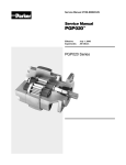
PGP030/031 Series
PGP050/051 Series
Effective: August 2002
Supersedes: June 1989
new photo
Service Manual HY09-SM030/031/050/051/US
Table of contents
Series PGP 030/031
Series PGP 050/051
DESCRIPTION
PAGE NO.
General Instructions ............................................ 3
Disassembly instructions .................................. 4-6
Assembly instructions ...................................... 6-9
Guidelines for acceptable wear ........................... 9
Tool list ............................................................... 10
Lubrication and oil recommendations ......... 11-12
Recommended start-up procedures
for new or rebuilt pump ...................................... 12
Recommended test procedure .......................... 13
Offer of sale ....................................................... 14
Use Genuine Parker Replacement Parts
WARNING
FAILURE OR IMPROPER SELECTION OR IMPROPER USE OF THE PRODUCTS AND/OR SYSTEMS DESCRIBED HEREIN OR RELATED ITEMS CAN CAUSE DEATH, PERSONAL
INJURY AND PROPERTY DAMAGE.
This document and other information from Parker Hannifin Corporation, its subsidiaries and authorized distributors provide product and/or system options for further investigation
by users having technical expertise. It is important that you analyze all aspects of your application and review the information concerning the product or system in the current
product catalog. Due to the variety of operating conditions and applications for these products or systems, the user, through its own analysis and testing, is solely responsible for
making the final selection of the products and systems and assuring that all performance, safety and warning requirements of the application are met.
The products described herein, including without limitation, product features, specifications, designs, availability and pricing, are subject to change by Parker Hannifin Corporation
and its subsidiaries at any time without notice.
Offer of Sale
The items described in this document are hereby offered for sale by Parker Hannifin Corporation, its subsidiaries or its authorized distributors. This offer and its acceptance are
governed by the provisions stated in the “Offer of Sale”.
2
Parker Hannifin Corporation
Gear Pump Division
Youngstown, OH
Service Manual HY09-SM030/031/050/051/US
General Instructions
Service Manual
Series PGP 030/031
Series PGP 050/051
PGP030/031/050/051
Service Manual
General Instructions
These service instructions will familiarize you with
Parker's single and multiple pumps:
• their component parts
• the relative position of each part
• proper methods for assembly or disassembly of
the units
To facilitate the repair of these units, and before
any work is done, we suggest that you first read
all of the steps used in disassembly and assembly.
Dirt is the enemy of any hydraulic system. The
first requirement of good maintenance of hydraulic
equipment is cleanliness. MAKE SURE YOU
DISASSEMBLE AND ASSEMBLE YOUR
HYDRAULIC EQUIPMENT IN A CLEAN AREA.
Our pictures show a Model PGP051. Notes in
the text cover variations between this unit and
the other models.
It is important to airblast all parts and wipe them
with a clean, lintless cloth before assembly.
USE CAUTION IN GRIPPING ALL PARTS IN THE
VISE TO AVOID DAMAGING
MACHINED SURFACES.
Items shaded apply to
multiple assemblies only.
A pump must be driven in the direction of rotation for
which it was built; otherwise, the pressure will blow
the shaft seal. Check the exploded view and notes at
right for proper direction of rotation.
Plug 5 in position B gives clockwise rotation.
Plug 5 in position A gives counterclock-wise rotation.
Check valves in both positions give bi-directional rotation.
Parker's Replacement Parts
Parker's replacement parts are of original equipment
standards. For assured quality of material and workmanship, and for compatibility in assembly, USE
ONLY GENUINE PARTS.
PARTS LIST
1.
2.
3.
4.
5.
Snap Ring
Outboard Bearing
Seal
Shaft End Cover
Check Assemblies
or Plug
6. Ring Seals
7. Roller Bearings
8. Pocket Seals
9. Thrust Plates
10. Integral Drive Shaft
and Gear Set
It is a good idea to check all replacement parts
before installing them to be certain that they were
not damaged in shipment.
3
11. Gasket Seals
12. Dowel Pins
(PGP031/051 only)
13. Bearing Carrier
14. Connecting Shaft
15. Matched Gear Set
16. Gear Housing
17. Port End Cover
18. Washers
19. Studs or Cap Screws
20. Nuts
Parker Hannifin Corporation
Gear Pump Division
Youngstown, OH
Service Manual HY09-SM030/031/050/051/US
Disassembly Instructions
Series PGP 030/031
Series PGP 050/051
Start Disassembly Here
CAUTION:
1. If prying off sections becomes necessary, take extreme care not to mar or damage machined surfaces. Excessive force while prying
can result in misalignment and seriously damage parts.
2. Do not force parts during assembly, and never use an iron hammer.
3. Gears are closely matched, therefore they must be kept together as sets, when removed from a unit. Handle with care to avoid
damage to the journals or teeth.
4. Never hammer roller bearings into bores. Use only an arbor press or other suitable tool.
1) Mount the pump in a vise
with the shaft end pointing
down. Index mark all
sections with a punch. Be
sure to align these marks
when reassembling.
2) Remove the 4 cap
screws on single units,
or the 4 hex nuts, studs,
and washers on multiple
units with a socket
wrench.
3) Lift off the port end cover.
If necessary to pry loose,
refer to caution note.
If the thrust plate remains
in the gear housing, it can
be tapped out later with a
wooden hammer handle.
Be careful not to distort
the thrust plate.
4) Lift the gear housing
from the gears. Take care
not to damage machined
surfaces.
For PGP031/051- Pry the
gear housing from the
gears and off the dowels
from opposite sides,
taking care not to
damage machined
surfaces.
For multiple assemblies only.
5) Carefully remove the
drive and driven gears,
without allowing the teeth to
come into rough handling
contact. Keep these gears
together, because they are
a matched set. Examine
and replace if necessary.
(See page 9.)
6) Lift or pry off the bearing
carrier carefully to prevent
damage to contact face
and edges.
For PGP031/051, pry the
bearing carrier off the
dowels from opposite
sides. Take care
not to damage the
machined surfaces.
Lift off the
bearing carrier.
For multiple assemblies only.
For multiple assemblies only.
4
Parker Hannifin Corporation
Gear Pump Division
Youngstown, OH
Service Manual HY09-SM030/031/050/051/US
Disassembly Instructions
Series PGP 030/031
7) Remove the drive gear
connecting shaft.
Series PGP 050/051
8) Lift or pry off the first
section gear housing. Be
careful not to damage
machined surfaces. If the
thrust plate remains in the
gear housing, remove as
described in Step 3.
For multiple assemblies only.
9) Remove the driven gear
and the integral gear and
drive shaft. Keep these
together as they are a
matched set. Examine
and replace if necessary.
Be careful not to damage
the machined surfaces of
the gears.
10) Pry the thrust plates
from the shaft end cover,
port end cover, or bearing
carrier with a screwdriver
or similar tool. Avoid
distorting the thrust plates.
Visually inspect thrust
plates for wear or damage.
Replace if necessary.
(See page 9.) Remove and
discard all rubber pocket
seals and gasket seals.
11) Examine all roller
bearings for scoring,
spalling, or pitting. If
replacement is necessary,
remove the bearings with
a bearing puller.
12) It is generally
advisable to replace ring
seals when rebuilding the
unit. To replace, remove
the drive gear bearing
with a bearing puller,
and remove the ring seal
from the bottom of the
bearing bore.
13) If the pump is
equipped with an outboard bearing, place the
shaft end cover in a vise
with the mounting face up.
Remove the bearing snap
ring with a small
screwdriver or awl.
14) Use a bearing puller
to remove the outboard
bearing.
5
Parker Hannifin Corporation
Gear Pump Division
Youngstown, OH
Service Manual HY09-SM030/031/050/051/US
Disassembly/Assembly Instructions
Series PGP 030/031
Series PGP 050/051
15) With the mounting face
down, remove the double lip
seal by inserting the special
seal removal tool (see Tool
List Pg. 10) into the notch
between the double lip seal
and the shaft end cover. Tap
the seal out and discard.
Start Assembly Here
1) Stone off all machined
surfaces with a mediumgrit, carborundum stone.
2) If the bearings have
been removed, deburr
bearing bores. Rinse
parts in a solvent. Air
blast all parts and wipe
with a clean, lintless cloth
before starting assembly.
3) Grip the shaft end
cover in a vise with the
mounting face down.
Examine the plug or the
2 check valves to be sure
that they're tightly in
place. Replacement is
necessary only if parts
are damaged. Remove
with a screwdriver or a
special check valve tool
(see Tool List page 10).
4) If plug or check valves
are being replaced, screw
in new parts tightly. Stake
the plug with a prick
punch at both ends of the
screwdriver slot and
around the edges. Screw
the check valves in tightly
with the tool. Peen edge
of hole 1/32" to 1/16" with
1-1/2" diameter steel ball.
6
Parker Hannifin Corporation
Gear Pump Division
Youngstown, OH
Service Manual HY09-SM030/031/050/051/US
Assembly Instructions
Series PGP 030/031
Series PGP 050/051
5) ASSEMBLY STEPS 5,
6, 7, 9 AND 11 APPLY TO
THE SHAFT END
COVER, BEARING
CARRIERS, AND THE
PORT END COVER.
If the ring seals are being
replaced, insert into the
bottom of drive the gear
bearing bore. The notch
in the ring seal MUST BE
VISIBLE. This is a check
to be certain that the
notched side is next to
the bearing.
6) If any bearings have
been removed from the
shaft end cover, port end
cover, or bearing carrier,
replace the bearings by
pressing them into the
bearing bore with an
arbor press.
7) Before inserting a new lip
seal in the shaft end cover,
coat the outer edge of the lip
seal and its recess with
Permatex Aviation Form-AGasket No. 3 Non-hardening
SealanTM or equivalent. With
the metal side of the lip seal
up, press it into the mounting
flange side of the shaft end
cover with an arbor press and
bar (See Tool List page10). On
the PGP030/031 series, make
certain that the lip seal is fully
seated in the recess. On the
PGP050/051 series, do not
attempt to bottom-out the seal;
press it in only until it is flush
with the face of the recess.
Wipe off surplus sealant.
8) Check all thrust
plates for wear. Replace
if necessary (see page 9).
Note that the thrust plates
for pumps and motors are
different. Pump thrust
plates have a single relief
pocket and must be
installed with this groove
on the high pressure side.
Motor thrust plates are
grooved on both sides.
9) Grip the shaft end
cover in a vise with the
mounting face down. Cut
2 pocket seals 7/32” long
from the pocket seal strip.
Grease these pocket
seals well and insert them
into the middle slots on
the reverse side of the
thrust plate.
motor
pump
For PGP031/051, the
relief groove on all the
unidirectional thrust plates
must be towards the high
pressure (outlet) side of
the pump.
PGP030/050 series pump
and motor plates resemble
the motor plate illustration.
10) With the pocket
seals facing down, place
the thrust plate over the
bearings in the shaft end
cover. Tap thrust plate
with a soft hammer to
about 1/32" from the
machined surface.
11) Cut 4 pocket seals
approximately 1/4" long from
the pocket seal strip. Insert
one pocket seal into each of
the slots in the thrust plate.
Push each pocket seal all the
way in so that it touches the
roller bearings. Tap the thrust
plate down firmly against the
machined surface with a soft
hammer. Use a sharp razor
blade to trim the exposed end
of the pocket seal square and
flush with the thrust plate.
7
12) Insert the splined
end of the drive shaft into
the special steel sleeve
(see Tool List page 10).
Lightly grease the drive
shaft and sleeve. Insert
the integral gear and
drive shaft with sleeve
into the shaft end cover
with a twisting motion.
Be careful not to damage
the double lip seal. Push
down carefully until the
gear rests against the
thrust plate. Remove the
steel sleeve. Insert the
driven gear.
Parker Hannifin Corporation
Gear Pump Division
Youngstown, OH
Service Manual HY09-SM030/031/050/051/US
Assembly Instructions
Series PGP 030/031
13) Grease the new gasket
seals and insert them into
the grooves in both sides
of all gear housings.
For the PGP031/051 Examine all dowel pins.
(See page 9.)* Before
inserting a pin, make certain
that the hole is clean and
free from burrs. Start the
pin into the hole gently and
straight, tapping lightly with
a soft hammer.
Series PGP 050/051
14) Slide the first section
gear housing over the
gears and tap it with a
soft hammer until it rests
tightly against the shaft
end cover.
Be careful not to pinch the
gasket seal. Squirt oil over
the gears to provide initial
lubrication when the pump
is started.
15) With the thrust plates
mounted on the bearing
carrier (as in steps 9, 10,
11), position it on the gear
housing so that the roller
bearings receive the journals
of the drive and driven
gears. Make sure that the
drain port in the bearing
carrier is on the suction or
inlet side if the unit is being
built as a pump. (Motors do
not have drain vents in the
bearing carrier.) Make sure
that the index marks are
properly aligned.
Insert dowel pins
(PGP031/051 only).
For multiple assemblies only.
17) Insert the drive and
the driven gears of the
second section into their
respective bearings.
Make certain gears are
in contact with the thrust
plate face.
For multiple assemblies only.
19) Place the port end
cover over the gear
journals and tap tightly
against the gear housing.
Be careful not to pinch the
gasket seal.
For PGP031/051 Align the
dowels with the holes in the
mating casting. Being
careful not to pinch the
gasket seal, tap the port
end cover lightly in the
center between bearing
bores to engage the dowels
and to move parts together
in final seating.
8
For the PGP031/051-Line
up the dowels with the
matching holes. When the
parts are parallel, squeeze
them together or gently tap
alternately over dowels
with a plastic hammer until
the parts become parallel
and move smoothly
together. Do not force.
16) Insert the connecting
shaft in the spline of the
drive gear.
For multiple assemblies only
18) Slide the second section
gear housing over the gears
and tap it tight against the
bearing carrier with a soft
hammer. Be careful not to
pinch the gasket seal. Squirt
oil over the gears to provide
initial lubrication when pump
is started.
For PGP031/051 line up the
dowels and the holes in the
2 castings. When parts are
parallel, squeeze them
together or gently tap
alternately over the dowels
with a plastic hammer
until parts move smoothly
together. Do not force. Insert
dowel pins (PGP031/051only).
For multiple assemblies only
20) Thread the 4 fasteners
(cap screws and washers,
or studs, washers, and
nuts) into the shaft end
cover and tighten
alternately or cross-corner.
Rotate the drive shaft with
a 6" wrench to make
certain there is no binding
in the pump.
Parker Hannifin Corporation
Gear Pump Division
Youngstown, OH
Service Manual HY09-SM030/031/050/051/US
Guidelines for Acceptable Wear
Series PGP 030/031
Series PGP 050/051
22) If the unit is equipped
with an outboard bearing,
guide the bearing into its
recess in the shaft end
cover. This is not a press
fit. Insert the snap ring
into its groove to retain
the outboard bearing.
21) After the fasteners are
tight and you are sure
there is no internal binding,
torque the diagonally
opposite fasteners to
200 ft. lbs. (2400 in. lbs.).
Guidelines for acceptable wear
Gear Housings
Wear in excess of .005" cutout necessitates
replacement of the gear housing.
Drive Shafts
Replace if there is any wear detectable by
touch in the seal areas or at the drive
coupling. .002" wear is the
maximum allowable.
Place a straight-edge across the bore. If you can slip
a .005" feeler gage under the straight-edge in the
cut-out area, replace the gear housing.
Wear in the shaft seal areas
indicates oil contamination. Wear or damage to
splines, keys or keyways necessitates replacement.
Pressure pushes the gears against
the housing on the low pressure side.
As the hubs and bearings wear, the
cutout becomes more pronounced.
Excessive cutout in a short period of
time indicates excessive pressure or
oil contamination. If the relief valve settings are within
prescribed limits, check for shock pressures or
tampering. Withdraw oil sample and check it and
the tank for dirt.
Thrust Plates
The thrust plates seal the gear section at the sides of
the gears. Wear here will allow internal slippage,
meaning the oil will bypass within the pump. The
maximum wear allowable is .002".
Replace the thrust plates if they are
scored, eroded or pitted. Check the
center of the thrust plates where the
gears mesh. Erosion here indicates oil
contamination. Pitted thrust plates
indicate cavitation or oil aeration. Discolored thrust
plates indicate overheating, probably insufficient oil.
Where cut-out is moderate, .005" or less, the gear
housing is in good condition, and both ports are of the
same size, the housing may be flipped over and reused.
Gears
Any wear on the gear hubs detectable by touch, or in
excess of .002" necessitates replacement. Scoring,
grooving, or burring of the outside
diameter of teeth requires replacement.
Nicking, grooving, or fretting of teeth
surfaces also necessitates replacement.
Dowel Pins
If either the dowel pin or dowel hole is damaged, the
pin, machined casting, or both, must be replaced.
If more than reasonable force is required
to seat dowels, the cause may be
poorly deburred or dirty parts; cocking
of dowel in the hole or improper pin-to-hole fit.
Continued on the following page
9
Parker Hannifin Corporation
Gear Pump Division
Youngstown, OH
Service Manual HY09-SM030/031/050/051/US
Tool List
Series PGP 030/031
Series PGP 050/051
Guidelines for Acceptable Wear continued
Check Valves
Examine the small check valves in the shaft
end cover to make sure that they are intact
and functioning. If there are no check valves
here, make sure that the high pressure side of the
shaft end cover is plugged.
Bearings
If the gears are replaced; the bearings must
also be replaced. Bearings should fit into the
bore with a light press fit. A near, hand-fit
is allowable.
Seals and Gaskets
Replace all of the rubber and polymer seals
whenever disassembling the pump. Include
all of the "O" rings, the pocket seals behind
the thrust plates, the shaft seal, and the gasket seals.
Tool List
•
•
•
•
•
•
•
•
•
•
•
•
•
•
•
•
•
•
•
•
Arbor press
Awl
1-1/2" dia. steel ball
Bearing puller (Owatonna Tool Co. MD-956 or
equivalent)
Clean, lintless cloths
Deburring tool (an old file with the cutting teeth
ground off)
Machinists hammer
Soft hammer
Permatex Aviation Form-A-Gasket No. 3
Non-hardening SealantTM or equivalent
Medium-grit, carborundum stone
Oil and grease
Snap-ring pliers
Prick punch
Sharp, razor blade
Scale (1/32" for graduations)
Small screwdriver
Torque wrench
Vise with 6" minimum open spread
Bar for lip seal installation
Note: For P30/P31, use 1-3/4" dia. by 2 bar.
For P50/P51, use 2-1/2" dia. by 2" bar.
Special steel sleeve
10
Parker Hannifin Corporation
Gear Pump Division
Youngstown, OH
Service Manual HY09-SM030/031/050/051/US
Lubrication and Oil Recommendations
Series PGP 030/031
Series PGP 050/051
Lubrication and Oil
Recommendations
All parts, with the exception of the outboard bearing,
are lubricated by the hydraulic oil in the circuit.
Particular attention must be paid to keep clean oil in
the circuit system. Whenever there is a pump or
motor failure, and there is reason to feel that metal
particles may be in the system, the oil must be
drained, the entire system flushed clean and any
filter screens thoroughly cleaned or replaced. New
oil should be supplied for the entire system. Oil
suitable and recommended for use in circuits
involving Parker's pumps and motors should meet
the following specifications:
Viscosity:
• 50 SSU minimum @ operating temperature
7500 SSU maximum @ starting temperature
• 150 to 225 SSU @ 100° F. (37.8°C.) (generally)
44 to 48 SSU @ 210° F. (98.9° C.) (generally)
Approximate SSU @
Viscosity Index: 90 minimum
Aniline Point: 175 minimum
Recommended Additives: Foam depressant,
rust and oxidation inhibitors.
Other Desirable Characteristics:
• Stability of physical and chemical characteristics.
• High demulsibility (low emulsibility) for separation
of water, air and contaminants.
• Resistant to the formation of gums, sludges, acids,
tars and varnishes.
• High lubricity and film strength.
General Recommendations:
A good-quality hydraulic oil conforming to the
characteristics listed above is essential to
the satisfactory performance and long life of any
hydraulic system.
Oil should be changed in regular schedules in
accordance with the manufacturer's recommendations,
and the system should also be periodically flushed.
Oil temperature in reservoir must not exceed 200° F.,
(93.3° C.) with a maximum temperature of 180° F.
(82.2° C.) recommended. Higher temperatures will
result in rapid oil deterioration.
Reservoir capacity should equal in gallons the pump
output in gpm or the total gpm of all pumps, where
there is more than one in the system.
Oil poured into the reservoir should pass through a 100
mesh screen. Pour only clean oil from clean containers
into the reservoir. A 100 mesh screen may be used in
the suction line leading to the pump. A suction filter
should be of sufficient size to handle twice the pump
capacity. It must be cleaned and checked regularly to
avoid damage due to contamination and cavitation.
Normal Temperatures:
O° F. (-1 8° C.) to 100° F. (37.8° C.) Ambient
100° F. (37.8° C.) to 180° F. (82.2° C.) System. Be sure
your oil is recommended for the temperatures you
expect to encounter.
Cold Weather Operation:
Oils for use in cold weather should have a viscosity
not exceeding 7500 SSU at the minimum start-up
temperature. A pour point of at least 20° F. below
start-up temperature is recommended. Start-up
procedures should allow for a gradual warm-up until
the oil reaches a reasonably fluid state.
Continued on the following page
11
Parker Hannifin Corporation
Gear Pump Division
Youngstown, OH
Service Manual HY09-SM030/031/050/051/US
Recommended Start-up Procedures
Series PGP 030/031
Series PGP 050/051
Lubrication and Oil Recommendations continued
Recommended Start-up
Procedure For New or
Rebuilt Pump
The Use of Other Fluids:
• Automatic Transmission Fluid (ATF): General
experience here has been satisfactory; however, ATF
oils are sometimes too expensive for normal use in
hydraulic systems.
Before installing a new or rebuilt pump, back off
the main relief valve until the spring tension on the
adjusting screw is relieved. This will avoid the
possibility of immediate damage to the replacement
unit in the event that the relief valve setting had
been increased beyond the recommended operating
pressure, prior to removing the old unit.
• Diesel Fuel or Kerosene (Coal Oil): Though
sometimes used as dilutants for cold weather
operations, these fluids are not recommended,
as they are not sufficiently refined products.
• Fire Resistant Fluids: Of the several different types,
only the inverted emulsion types may be used without
changing to special seals, packing, gasket, hose, etc.,
compositions. Their use may materially reduce pump
life. Experience indicates that the use of FR fluids can
be disastrous unless certain precautions are followed.
DO NOT USE ANY FIRE RESISTANT FLUIDS OR
NON-PETROLEUM OILS WITHOUT CONSULTING
OUR TECHNICAL SERVICE DEPARTMENT.
• These suggestions are intended as a guide only.
OBTAIN YOUR FINAL FLUID RECOMMENDATIONS
FROM YOUR FLUID SUPPLIER.
Before connecting any lines to the pump, fill all ports
with clean oil to provide initial lubrication. This is
particularly important if the unit is located above the
oil reservoir.
After connecting the lines and mounting the
replacement unit, operate the pump at least two
minutes at no load and at low rpm (400 min.) During
this break-in period, the unit should run free and not
develop an excessive amount of heat. If the unit
operates properly, speed and pressure can then be
increased to normal operating settings.
Reset the main relief valve to its proper setting while
the pump is running at maximum operating engine
(motor) speed for the vehicle.
ALWAYS USE AN ACCURATE GAUGE
WHEN ADJUSTING THE RELIEF VALVE
PRESSURE SETTING.
12
Parker Hannifin Corporation
Gear Pump Division
Youngstown, OH
Service Manual HY09-SM030/031/050/051/US
Recommended Test Procedures
Series PGP 030/031
Series PGP 050/051
Recommended
Test Procedure
To be sure that there is an adequate supply of oil for
the pump, maintain at least one gallon of oil for each
gpm of pump capacity.
rebuild the pump, however, the performance
rating may decrease. (A 10-15% lower rating can
be expected.)
If one section of a tandem pump is being tested,
make sure that all other sections not being tested
are adequately supplied with oil. If any of the other
sections run dry, or if the plugs are left in the ports,
serious and permanent damage will result.
Many repairmen measure the output at normal
operating speed and at zero pressure, then again at
1000 psi (or the operating pressure of the equipment), and allow a volume decrease approximating
the listing below. This is a suggested reference, only
which makes allowance for re-used parts.
The oil should be a good-quality hydraulic oil rated
at 150 SSU at 100° F., with the oil temperature held
at 120° F. plus or minus 5°F. (Test procedures are
described in detail in SAE handbooks; see Hydraulic
Power Pump Test Procedure, SAE J745c.)
PGP030/050 pumps are generally tested to 2000 psi
maximum.
At test speeds other than 1800 rpm, gpm delivery
will vary almost proportionately, but the same
(drop-off) figures should be used.
The feed line must be of adequate size with no more
than 5" mercury vacuum adjacent to the pump inlet. As
a rule, the feed line must provide a feed flow velocity
not in excess of 8 feet per second.
Be sure to run the pump in the direction for which
it was designed and built. Driving the pump in the
wrong direction will build up pressure behind the shaft
seal, damaging it and necessitating replacement.
Hot oil must not be fed into a cold pump. It may seize.
Jogging the pump may prevent seizure.
Since it is rarely feasible to test motors on
dynamometers, the practical procedure is to test them
as pumps, running complete testing procedures in
each direction.
Operate the pump at least two minutes at zero
pressure and at moderate speed (not over 1500 rpm)
If the pump becomes hot to touch, it is binding and
may seize. This doesn't happen often, but if it does,
the pump will have to be disassembled and rebuilt,
with extra care taken to remove burrs and to assure
freedom from binding.
After completing testing procedures, the pump is
ready for installation and immediate duty operation
on the equipment. Again, it must be remembered
that to prevent seizure, hot oil must not be fed into
a cold pump.
Gradually increase pressure on the pump, until the
desired test pressure has been reached. This should
take about five minutes.
Pump output flow should run close to rated catalog
performance figures, which are averaged from testing
several pumps. A 5% lower reading may be used as a
rated minimum if new or relatively new parts have
been used. Worn parts, which meet the guidelines for
acceptable wear, (See page 9) may be used to
13
Parker Hannifin Corporation
Gear Pump Division
Youngstown, OH
Offer of Sale
The items described in this document and other documents or descriptions provided by Parker Hannifin Corporation, its subsidiaries and its authorized
distributors are hereby offered for sale at prices to be established by Parker Hannifin Corporation, its subsidiaries and its authorized distributors. This
offer and its acceptance by any customer ("Buyer") shall be governed by all of the following Terms and Conditions. Buyer’s order for any such items,
when communicated to Parker Hannifin Corporation, its subsidiary or an authorized distributor ("Seller") verbally or in writing, shall constitute acceptance
of this offer.
1. Terms and Conditions of Sale: All descriptions, quotations, proposals,
offers, acknowledgments, acceptances and sales of Seller’s products are
subject to and shall be governed exclusively by the terms and conditions
stated herein. Buyer’s acceptance of any offer to sell is limited to these
terms and conditions. Any terms or conditions in addition to, or inconsistent
with those stated herein, proposed by Buyer in any acceptance of an offer
by Seller, are hereby objected to. No such additional, different or inconsistent terms and conditions shall become part of the contract between Buyer
and Seller unless expressly accepted in writing by Seller. Seller’s acceptance of any offer to purchase by Buyer is expressly conditional upon
Buyer’s assent to all the terms and conditions stated herein, including any
terms in addition to, or inconsistent with those contained in Buyer’s offer,
Acceptance of Seller’s products shall in all events constitute such assent.
2. Payment: Payment shall be made by Buyer net 30 days from the date
of delivery of the items purchased hereunder. Amounts not timely paid
shall bear interest at the maximum rate permitted by law for each month or
portion thereof that the Buyer is late in making payment. Any claims by
Buyer for omissions or shortages in a shipment shall be waived unless
Seller receives notice thereof within 30 days after Buyer’s receipt of the
shipment.
3. Delivery: Unless otherwise provided on the face hereof, delivery shall
be made F.O.B. Seller’s plant. Regardless of the method of delivery,
however, risk of loss shall pass to Buyer upon Seller’s delivery to a carrier.
Any delivery dates shown are approximate only and Seller shall have no
liability for any delays in delivery.
4. Warranty: Seller warrants that the items sold hereunder shall be free
from defects in material or workmanship for a period of 18 months from date
of shipment from Parker Hannifin Corporation. THIS WARRANTY COMPRISES THE SOLE AND ENTIRE WARRANTY PERTAINING TO ITEMS
PROVIDED HEREUNDER. SELLER MAKES NO OTHER WARRANTY,
GUARANTEE, OR REPRESENTATION OF ANY KIND WHATSOEVER.
ALL OTHER WARRANTIES, INCLUDING BUT NOT LIMITED TO, MERCHANTABILITY AND FITNESS FOR PURPOSE, WHETHER EXPRESS,
IMPLIED, OR ARISING BY OPERATION OF LAW, TRADE USAGE, OR
COURSE OF DEALING ARE HEREBY DISCLAIMED.
NOTWITHSTANDING THE FOREGOING, THERE ARE NO WARRANTIES WHATSOEVER ON ITEMS BUILT OR ACQUIRED WHOLLY OR
PARTIALLY, TO BUYER’S DESIGNS OR SPECIFICATIONS.
5. Limitation Of Remedy: SELLER’S LIABILITY ARISING FROM OR IN
ANY WAY CONNECTED WITH THE ITEMS SOLD OR THIS CONTRACT
SHALL BE LIMITED EXCLUSIVELY TO REPAIR OR REPLACEMENT OF
THE ITEMS SOLD OR REFUND OF THE PURCHASE PRICE PAID BY
BUYER, AT SELLER’S SOLE OPTION. IN NO EVENT SHALL SELLER
BE LIABLE FOR ANY INCIDENTAL, CONSEQUENTIAL OR SPECIAL
DAMAGES OF ANY KIND OR NATURE WHATSOEVER, INC.
LUDING BUT NOT LIMITED TO LOST PROFITS ARISING FROM OR IN
ANY WAY CONNECTED WITH THIS AGREEMENT OR ITEMS SOLD
HEREUNDER, WHETHER ALLEGED TO ARISE FROM BREACH OF
CONTRACT, EXPRESS OR IMPLIED WARRANTY, OR IN TORT, INCLUDING WITHOUT LIMITATION, NEGLIGENCE, FAILURE TO WARN
OR STRICT LIABILITY.
6. Changes, Reschedules and Cancellations: Buyer may request to
modify the designs or specifications for the items sold hereunder as well
as the quantities and delivery dates thereof, or may request to cancel all
or part of this order, however, no such requested modification or cancellation shall become part of the contract between Buyer and Seller unless
accepted by Seller in a written amendment to this Agreement. Acceptance
of any such requested modification or cancellation shall be at Seller’s
discretion, and shall be upon such terms and conditions as Seller may
require.
7. Special Tooling: A tooling charge may be imposed for any special
tooling, including without limitation, dies, fixtures, molds and patterns,
acquired to manufacture items sold pursuant to this contract. Such special
tooling shall be and remain Seller’s property notwithstanding payment of
any charges by Buyer. In no event will Buyer acquire any interest in
apparatus belonging to Seller which is utilized in the notwithstanding any
charges paid by Buyer. Unless otherwise agreed, Seller shall have the
right to alter, discard or otherwise dispose of any special tooling or other
property in its sole discretion at any time.
8. Buyer’s Property: Any designs, tools, patterns, materials, drawings,
confidential information or equipment furnished by Buyer or any other
items which become Buyer’s property, may be considered obsolete and
may be destroyed by Seller after two (2) consecutive years have elapsed
without Buyer placing an order for the items which are manufactured using
such property, Seller shall not be responsible for any loss or damage to
such property while it is in Seller’s possession or control.
9. Taxes: Unless otherwise indicated on the face hereof, all prices and
charges are exclusive of excise, sales, use, property, occupational or like
taxes which may be imposed by any taxing authority upon the manufacture, sale or delivery of the items sold hereunder. If any such taxes must
be paid by Seller or if Seller is liable for the collection of such tax, the
amount thereof shall be in addition to the amounts for the items sold. Buyer
agrees to pay all such taxes or to reimburse Seller therefore upon receipt
of its invoice. If Buyer claims exemption from any sales, use or other tax
imposed by any taxing authority, Buyer shall save Seller harmless from and
against any such tax, together with any interest or penalties thereon which
may be assessed if the items are held to be taxable.
10. Indemnity For Infringement of Intellectual Property Rights: Seller
shall have no liability for infringement of any patents, trademarks, copyrights, trade dress, trade secrets or similar rights except as provided in this
Part 10. Seller will defend and indemnify Buyer against allegations of
infringement of U.S. Patents, U.S. Trademarks, copyrights, trade dress
and trade secrets (hereinafter ‘Intellectual Property Rights’). Seller will
defend at its expense and will pay the cost of any settlement or damages
awarded in an action brought against Buyer based on an allegation that an
item sold pursuant to this contract infringes the Intellectual Property Rights
of a third party. Seller’s obligation to defend and indemnify Buyer is
contingent on Buyer notifying Seller within ten (10) days after Buyer
becomes aware of such allegations of infringement, and Seller having sole
control over the defense of any allegations or actions including all
negotiations for settlement or compromise. If an item sold hereunder is
subject to a claim that it infringes the Intellectual Property Rights of a third
party, Seller may, at its sole expense and option, procure for Buyer the right
to continue using said item, replace or modify said item so as to make it
noninfringing, or offer to accept return of said item and return the purchase
price less a reasonable allowance for depreciation. Notwithstanding the
foregoing, Seller shall have no liability for claims of infringement based on
information provided by Buyer, or directed to items delivered hereunder for
which the designs are specified in whole or part by Buyer, or infringements
resulting from the modification, combination or use in a system of any item
sold hereunder. The foregoing provisions of this Part 10 shall constitute
Seller’s sole and exclusive liability and Buyer’s sole and exclusive remedy
for infringement of Intellectual Property Rights.
If a claim is based on information provided by Buyer or if the design for an
item delivered hereunder is specified in whole or in part by Buyer, Buyer
shall defend and indemnify Seller for all costs, expenses or judgments
resulting from any claim that such item infringes any patent, trademark,
copyright, trade dress, trade secret or any similar right.
11. Force Majeure: Seller does not assume the risk of and shall not be
liable for delay or failure to perform any of Seller’s obligations by reason of
circumstances beyond the reasonable control of Seller (hereinafter ‘Events
of Force Majeure’). Events of Force Majeure shall include without limitation, accidents, acts of God, strikes or labor disputes, acts, laws, rules or
regulations of any government or government agency, fires, floods, delays
or failures in delivery of carriers or suppliers, shortages of materials and
any other cause beyond Seller’s control.
12. Entire Agreement/Governing Law: The terms and conditions set forth
herein, together with any amendments, modifications and any different
terms or conditions expressly accepted by Seller in writing, shall constitute
the entire Agreement concerning the items sold, and there are no oral or
other representations or agreements which pertain thereto. This Agreement shall be governed in all respects by the law of the State of Ohio. No
actions arising out of the sale of the items sold hereunder or this Agreement
may be brought by either party more than two (2) years after the cause of
action accrues.
9/91-P
14
Parker Hannifin Corporation
Gear Pump Division
Youngstown, OH
Parker Hannifin Corporation
6035 Parkland Blvd.
Cleveland, Ohio 44124-4141
Telephone: (216) 896-3000
Fax: (216) 896-4000
www.parker.com
Parker Hannifin Corporation
About Parker Hannifin Corporation
Parker Hannifin is a leading global motion-control
company dedicated to delivering premier customer
service. A Fortune 500 corporation listed on the New
York Stock Exchange (PH), our components and
systems comprise over 1,400 product lines that control
motion in some 1,000 industrial and aerospace markets.
Parker is the only manufacturer to offer its customers a
choice of hydraulic, pneumatic, and electromechanical
motion-control solutions. Our
Company has the largest distribution network in its
field, with over 7,500 distributors serving nearly
400,000 customers worldwide.
Parker’s Charter
To be a leading worldwide manufacturer of components
and systems for the builders and users of durable
goods. More specifically, we will design, market and
manufacture products controlling motion, flow and
pressure. We will achieve profitable growth through
premier customer service.
Product Information
North American customers seeking product information, the location of a nearby distributor, or repair
services will receive prompt attention by calling the
Parker Product Information Center at our toll-free
number: 1-800-C-PARKER (1-800-272-7537). In Europe,
call 00800-C-PARKER-H (00800-2727-5374).
The Aerospace Group
is a leader in the development,
design, manufacture and
servicing of control systems
and components for aerospace
and related high-technology
markets, while achieving
growth through premier
customer service.
The Climate & Industrial
Controls Group
designs, manufactures and
markets system-control and
fluid-handling components
and systems to refrigeration,
air-conditioning and industrial
customers worldwide.
The Fluid Connectors
Group designs, manufactures
and markets rigid and flexible
connectors, and associated
products used in pneumatic
and fluid systems.
The Seal Group designs,
manufactures and distributes
industrial and commercial
sealing devices and related
products by providing
superior quality and
total customer satisfaction.
The Hydraulics Group
designs, produces and
markets a full spectrum
of hydraulic components
and systems to builders
and users of industrial
and mobile machinery
and equipment.
The Filtration Group
designs, manufactures and
markets quality filtration
and clarification products,
providing customers with
the best value, quality,
technical support, and
global availability.
The Automation Group
is a leading supplier of
pneumatic and electromechanical components
and systems to automation
customers worldwide.
The Instrumentation
Group is a global leader
in the design, manufacture
and distribution of highquality critical flow
components for worldwide
process instrumentation,
ultra-high-purity, medical
and analytical applications.
15
Parker Hannifin Corporation
Gear Pump Division
Youngstown, OH
Parker Hannifin Corporation
Gear Pump Division
1775 Logan Avenue
Youngstown, OH 44501 USA
Tel: (330) 746-8011
Fax: (330) 746-1148
www.parker.com
Service Manual
HY09-SM030/031/050/051/US
08/02 T&M 2.5M


![Page 1 www.Ludowici.com [**INSERT PIC] LUDOWICI TM Desde](http://vs1.manualzilla.com/store/data/006216944_1-046022ddb0fd4b43a805da73ee2d4dd9-150x150.png)