1
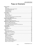
2
L599003-13
109
1
B
1
3
Figure 6-1 HO303 / EX343 Raw Water Cooling
CAUTION: If compressed air is used to purge Heater, use no
more than 10psi. The heater core can be damaged from
excessive air pressure.
NOTE: (If Equipped) Remove heater hoses from locations A and B.
A
3
1 - Engine Block Drains - Remove Knock Sensors
2 - Engine Circulating Water Pump Pipe - Remove Drain Plug
3 - Exhaust Manifolds - Remove Drain Plugs
4 - Transmission Cooler - Remove Inlet Hose
5 - VDrive - Remove Drain Plug
Drain Locations
1/2”
Square
PCM V-Drive
5
Raw Water
Drain Plug
MADE IN USA
PLEASURECRAFT
ENGINE GROUP
POWER PLUS
1.48
RATIO
Note: This diagram is for illustration purposes only. The actual
routing and/or shape of the hoses may vary slightly depending
on installation.
4
From Sea
Water Pickup
5
COOLING SYSTEM - 6