1
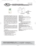
E-90-TSF:Series QV (F-87)
6/1/10
1:58 PM
Page 1
Bulletin E-90-TSF
Series TSF Thermocouple Limit Control
Specifications - Installation and Operating Instructions
1.34
[34]
1.10
[28]
2.72
[69]
2.95
[75]
The Series TSF Thermocouple FM Approved Limit Control provides
audible alarm status along with a robust 15 amp relay output. Unit allows
the user to easily select automatic or manual reset along with 10 other
parameters. The TSF series has a built in reset button on the front panel
or can accept an external reset.
The ease of programming and low price make the TSF series the best
value limit control on the market.
Model References:
The model reference is given by TSF-WXYZ. Where each suffix can take
the following values:
W Thermocouple Type
X Display Color
Y Supply Voltage
Z
Units
4=J
0=Red, 1=Green
1=115 VAC
2=230 VAC
3=12 VAC
4=24 VAC
0˚F, 1=˚C
SPECIFICATIONS
Probe Range: 0 to 700°C (32 to 999°F) for thermocouple J type. 0 to
999°C (32 to 999°F) for thermocouples K or S type.
Input: J, K, or S type thermocouple.
Output: 15 A SPDT relay @ 250 VAC resistive.
Horsepower Rating (HP): 3/4 HP.
Control Type: ON/OFF; manual/automatic reset.
Power Requirements: 110 VAC, 230 VAC, 12 VAC/VDC or 24
VAC/VDC (depending on model).
Power Consumption: 4 VA.
Accuracy: ±1% FS.
Display: 3-digit, red, 1/2˝ (12.7 mm) digits, plus sign.
Resolution: 1°.
Memory Backup: Nonvolatile memory.
Ambient Operating Temperature: 14 to 131°F (-10 to 55°C).
Storage Temperature: -4 to 176°F (-20 to 80°C).
Weight: 2.3 oz (65 g).
Front Panel Rating: IP64.
Agency Approvals: CE, FM, UL.
Wiring Diagram:
INSTALLATION
NOTE: Unit must be mounted away from vibration, impacts, water and
corrosive gases.
Cut hole in panel 2.80 x 1.14 inches (71 X 29 mm).
Apply silicone (or rubber gasket) around the perimeter of the hole to
prevent leakage.
Input
Probe
1 2 3 4
+
5 6 7 8 9
POWER
SUPPY
NC COM NO
OUTPUT
Insert unit into the hole of panel.
LOVE CONTROLS DIVISION
DWYER INSTRUMENTS INC.
P.O. BOX 338 - MICHIGAN CITY, INDIANA 46361, U.S.A.
Phone: 219/879-8000 www.love-controls.com
Fax: 219/872-9057 e-mail:[email protected]
E-90-TSF:Series QV (F-87)
6/1/10
List of Parameters
Description
SP Set Point
r0 Differential or Hysteresis
r1 Lower Value for SP
r2 Higher Value for SP
r3 Reset of Control
d0 High or low limit temperature
c0 Minimum stopping time
c2 Output status with probe
c3 Alarm energize condition
P1 Ambient Probe Adjustment
P5 Ambient Probe Type
H5 Access code to parameters
1:58 PM
Units
Degrees
Degrees
Degrees
Degrees
Option
Option
Seconds
Range
Option
Degrees
Range
Numeric
Page 2
Range
r1 to r2
1 to 99
0 to r2
r1 to 999
Aut/hoL
Hi/Lo
0 to 999
Off/On
No/Yes
-30 yp 30
tcJ, tch, tcS
0 to 255
Access to all code protected parameters:
Press SET for 8 seconds. The access code value 0 is shown on the
display (unit comes with code set at 0 from the factory).
With the UP and DOWN arrows, code can be set to user needs.
Press SET to enter the code. If the code is correct, the first parameter
label is shown on the display (SP).
Move the desired parameter with the UP and DOWN arrows.
Press SET to view the value on the display.
The value can be modified with the UP and DOWN arrows.
Press SET to enter the value and exit.
Parameter Descriptions:
SP = Set Point. Temperature we wish to activate relay output.
r0 = Differential or hysteresis.
r1 = Lower value for SP.
r2 = Higher value for SP.
d0 = High or low temperature control.
Where TS is the temperature ambient of the probe.
If d0 = Hi and r3 = Aut:
If TS ≥ SP relay output ON, Buzzer ON, AL displayed.
If TS ≤ SP - r0 relay output OFF, buzzer OFF, TS displayed.
If d0 = Hi and r3 = hoL:
If TS ≥ SP relay output ON, buzzer ON, AL displayed.
If TS ≤ SP - r0 it waits for reset of relay output OFF, buzzer, TS
displayed.
If d0 = Lo and r3 = Aut:
If TS ≤ SP relay output ON, buzzer ON, AL displayed.
If TS ≥ SP + r0 relay output OFF, buzzer OFF, TS displayed.
If d0 = Lo and r3 = hoL:
If TS ≤ SP relay ON, buzzer ON, AL displayed.
If TS ≥ SP + r0 it waits for reset to relay output OFF, buzzer
OFF, TS displayed.
c0 = Minimum stopping time of the load.
c2 = Output status with probe error.
c3 = Energize relay on alarm condition (Determines fail state during
power loss).
Yes = Relay energized during alarm condition,
No = Relay de-energized during alarm condition.
P1 = Ambient probe adjustment.
P5 = Ambient probe type.
P5 = tcJ (J Type), P5 = tch (K Type), P5 = tcS (S Type).
H5 = Access code to parameters (it is set to 0 from factory).
PARAMETER PROGRAMMING
Set Point (SP) is the only parameter the user can access with code
protection.
Press SET. SP text will appear on the display.
Press SET again. The real value is shown on the display.
The value can be modified with the UP and DOWN arrows.
Press SET to enter any new values.
Press SET and DOWN at the same time to quit programming or wait one
minute and the display will automatically exit the programming mode.
©Copyright 2010 Dwyer Instruments, Inc.
LOVE CONTROLS DIVISION
DWYER INSTRUMENTS INC.
P.O. BOX 338 - MICHIGAN CITY, INDIANA 46361, U.S.A.
Repeat until all necessary parameters are modified.
Press SET and DOWN at the same time to quit programming or wait one
minute and the display will automatically exit programming mode.
*The keyboard can be reset to ZERO by turning off the controller and
turning it on again while keeping the SET key depressed.
Reset an alarm:
When the parameter r3 = hoL, once the relay output and alarm are
activated (because of temperature ambient TS), these remain activated
until a reset is received (by pressing the reset key or by closing contact
in rear input). When d0 = Hi the reset is accepted if temperature ambient
is below TS ≤ SP - r0. When d0 = Lo the reset is accepted if temperature
ambient TS is over TS ≥ SP + r0.
LED indication, buzzer and display messages:
The LED Alarm indicates if the relay output is connected or not. When
the relay output is connected the message AL is displayed alternated
with the temperature ambient of the probe.
In normal operation the probe temperature will be shown on the display.
In case of alarm or error, the following messages can be shown:
Erl = memory error
˚˚˚ = open probe error
--- = ambient temperature out to range
In case of alarm or error the internal buzzer is activated. The buzzer can
be silenced by pressing the SET and DOWN arrows at the same time
(when a new alarm or error occurs the buzzer will sound again).
MAINTENANCE
Upon final installation of the Series TSF Thermocouple Limit Control, no
routine maintenance is required. A periodic check of the system
calibration is recommended. The Series TSF is not field serviceable and
should be returned if repair is needed (field repair should not be
attempted and may void warranty). Be sure to include a brief description
of the problem plus any relevant application notes. Contact customer
service to receive a return goods authorization number before shipping.
Cleaning and Repair:
Clean the surface of the display controller with a soft damp cloth. Never
use abrasive detergents, petrol, alcohol or solvents.
Printed in U.S.A. 6/10
FR# 443532-00 Rev. 2
Phone: 219/879-8000 www.love-controls.com
Fax: 219/872-9057 e-mail:[email protected]