1
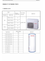
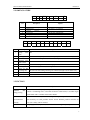
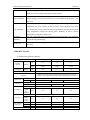
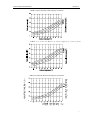
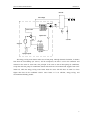
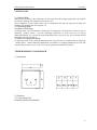
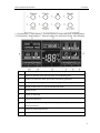
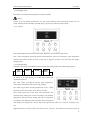
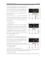
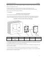
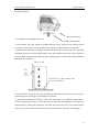
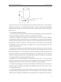
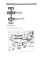
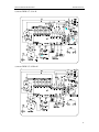
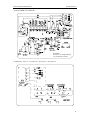
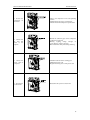
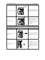
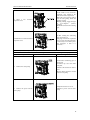
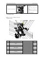
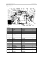
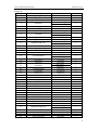
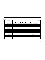
CONTENTS
PRODUCT INTRODUCTION ...................................................................................2
1 MODELS LIST ............................................................................................................................. 2
2 NOMENCLATURE ...................................................................................................................... 3
3 FUNCTION .................................................................................................................................. 3
4 PRODUCT DATA ......................................................................................................................... 4
4.1 Product Data at Rated Condition ........................................................................................ 4
4.2 Operation Range................................................................................................................. 6
4.3 Operation Performance ...................................................................................................... 6
5 PIPING DIAGRAM ...................................................................................................................... 8
UNITS CONTROL .................................................................................................... 11
1 OPERATION FLOWCHART ..................................................................................................... 11
2 MAIN LOGIC ............................................................................................................................. 12
2.1 Heating Mode ................................................................................................................... 12
2.2 Defrosting Mode .............................................................................................................. 12
3 WIRED REMOTE CONTROLLER ........................................................................................... 12
3.1 Dimension ........................................................................................................................ 12
3.2 Function ........................................................................................................................... 12
3.3 Installation ........................................................................................................................ 17
INSTALLATION ........................................................................................................20
1 UNITS INSTALL........................................................................................................................ 20
1.1 Installation Positions ........................................................................................................ 20
1.2 Matters need Attention ..................................................................................................... 20
1.3 Dimension Data................................................................................................................ 20
2 ELECTRIC WIRING WORK ..................................................................................................... 24
2.1 Wiring Principle ............................................................................................................... 24
2.2 Electric Wiring Design ..................................................................................................... 24
2.3 Specification of Power Cord & Air Switch ...................................................................... 26
UNITS MAINTENANCE ..........................................................................................29
1 ERROR CODE LIST .................................................................................................................. 29
2 FLOW CHART OF TROUBLESHOOTING.............................................................................. 30
3 WIRING DIADRAM .................................................................................................................. 34
4 DISASSEMBLY AND ASSEMBLY PROCEDURE OF MAIN PARTS.................................... 37
5 EXPLODED VIEWS .................................................................................................................. 43
PRODUCT
1
HEAT PUMP WATER HEATER
PRODUCT
2 NOMENCLATURE
DHW
-
2
1
NO.
1
3.5
3
C
4
NO.
Description
1
2
INVENTOR Heat Pump Water Heater
Heating style
-
A1
5
/
Options
Capacity
DHW
S= Static ,C =Circulating
3
4
Heating
Refrigerant
Nb=R134a, Default=R22
5
6
Design Serial Number
Power
style
A1
3.5KW
220~240V-1Ph-50Hz
WT-SX
D
250
L
C
1
2
3
4
5
6
7
Description
Symbol of heat
pump
water
tank
K
6
/
B1
8
-
K
9
Options
WT
2
Tank type
Lack-common heat pump water tank; V- heat pump water tank for multi VRF system
3
Function code
Lack-no electric heating function; D- electric heating function available
4
Nominal water
tank volume
100=100L 150=150L 200=200L
5
Structure type
B-Wall Mounted Type˗L-Floor Standing Type
6
Bearing
Lack-non-bearing water tank; C-bearing water tank
7
Type of heat
exchange tube
Lack-no heat exchanger; J-inner coil static heating(J-single coil; J2-double coils);
JW-outer coil static heating; D-heating coil with floor (D-single coil; D2-double coils)
8
Serial number
AǃBǃC……
9
Power
220~240V-1Ph-50Hz
3 FUNCTION
Function
Efficient
Description
and
energy saving
Safe
The unit is automatically adjusted by electronic expansion valve.
COP is 3-5. Running cost is 1/4 of that of electric water heater, 1/3 of that of gas
water heater and 1/2 of that of fuel water heater.
and
There is no need of any electric heating or complete separation between water
environmental
and electricity to avoid possible electric shock. Without possible toxicities of
friendly
CO, user’s safety can be ensured.
Reliable
and
Adopting special compressor, the unit is resistant to high temp and pressure. The
3
HEAT PUMP WATER HEATER
durable
PRODUCT
water tank adopts advanced stainless steel inner container with ultra-long dual
magnesium sticks to ensure long lifespan of the system.
Without limitation of environment, the unit can be installed in kitchen, bathroom,
Easy installation
balcony, garage, stock room or basement. It is also suitable for skyscrapers, villa,
and so on.
Water temperature can be set. Water supply can be on or off depending on water
temperature and water volume, so that hot water can be supplied at any time.
Easy operation
Unit on/off can be set by user according to requirements (the unit will stop once
water temperature reaches the setting point). Running of unit in electric
platykurtosis is possible to reduce cost.
Intelligent
The unit with anti-freezing and intelligent defrosting functions can efficiently
defrosting
prevent freezing and frosting.
The unit can make and supply hot water all day in despite of night, overcast and
All-day use
rainy days.
4 PRODUCT DATA
4.1 Product Data at Rated Condition
DHW-C3.5/A1-K
Models
Nominal
Capacity
DHW-C5.0/A1-K
DHW-C7.2/A1-K
kW
3.5
5.0
7.2
Btu/h
11942
17060
24566
kW
0.9
1.15
1.75
Heating
Power
Heating
Consumption
Power Supply
220-240V ~1Ph~50Hz
High/Low pressure switch, compressor thermal protection, overcurrent
protection, lack of phase/anti-phase protection, antifreezing protection, R22
Safeties
Refrigerant
Compressor
Type
Charge
Type
NO.
R22
kg
0.65
1
Heat Exchanger
Condenser
Evaporator
Unit / Packing
Dimension
Water
In/Out
Pipe
Diameter
Inch
Heat Exchanger
Fan
Motor
W
Power
Input
Height
mm
Width
Depth
Net/Gross Weights
mm
mm
kg
1.0
Rotary
1
1.0
1
Tube-in-tube
3/4
3/4
3/4
Fin type heat exchanger
30
30
48
750/800
750/800
882/930
762/878
256/360
50/56
762/878
256/360
55/61
870/994
378/428
68/79
4
HEAT PUMP WATER HEATER
PRODUCT
DHW-C3.8/NbA-K
Models
Nominal
Capacity
DHW-C5.0/ NbA-K
kW
3.8
5.0
Btu/h
12966
17060
kW
1.02
1.35
Heating
Power
Consumption
Heating
220-240V ~1Ph~50Hz
High/Low pressure switch, compressor thermal protection,
overcurrent protection, lack of phase/anti-phase protection,
antifreezing protection, R134a
Power Supply
Safeties
Type
Charge
Type
NO.
Refrigerant
Compressor
R134a
kg
0.7
0.95
Rotary
1
Heat Exchanger
1
Tube-in-tube
Water
Condenser
In/Out Pipe
Inch
Diameter
Heat Exchanger
Fan Motor
Evaporator
Power
W
Input
Height
mm
Unit / Packing
Width
mm
Dimension
Depth
mm
Net/Gross Weights
kg
3/4
3/4
Fin type heat exchanger
30
30
750/800
762/878
256/360
55/61
750/800
762/878
256/360
60/66
Note:1Ton =12000Btu/h = 3.517kW
Water tank model WT-SX150LC/B1-K WT-SX200LC/B1-K WT-SX250LC/B1-K WT-SX300LC/B1-K
Capacity
L
150
200
250
300
WT-SX350LC/B1-K
WT-SX400LC/B1-K
350
400
Outline
dimension mm 520×1350
540×1595
540×1945
620×1620
620×1895
˄OD×H˅
Package
mm 1375×610×605 1620×630×625 1970×630×625 1645×710×705 1920×710×705
(W*D*H)
620×2125
2150×710×705
kg
42
55
66
69
77
84
Gross weight kg
50
63
75
79
88
96
DN20
DN20
DN20
DN20
DN20
DN20
DN15
DN15
DN15
DN15
DN15
DN15
Net weight
Dimension of
connecting
pipe between mm
main unit and
water tank
Connecting
dimension of
mm
water pipe
terminal
5
HEAT PUMP WATER HEATER
Water tank model
PRODUCT
WT-150LC-K
WT-200LC-K
WT-250LC-K
WT-300LC-K
Capacity
L
150
200
250
300
Outline dimension
˄OD×H˅
mm
520×1350
540×1595
540×1945
620×1620
mm
kg
kg
1375×610×605
1620×630×625
1970×630×625
1645×710×705
45
57
68
71
52
66
77
81
mm
DN20
DN20
DN20
DN20
mm
DN15
DN15
DN15
DN15
Package (W*D*H)
Net weight
Gross weight
Dimension of
connecting pipe
between main unit and
water tank
Connecting dimension
of water pipe terminal
(1) Test conditions of the above data: outdoor ambient temp: 20ćDB/15ćWB, water tank initial/
ending temp: 15ć/55ć
(2) If there is any change of product specification, please refer to the nameplate.
4.2 Operation Range
Model
Heating
Range of Outdoor Temperatureć (̧)
-7~45ć
4.3 Operation Performance
During heating, the water is heated by the unit absorbing heat energy from outside and then releasing it
to the water in water tank. Heating capacity may be reduced if outdoor temperature is decreased. The
following chart is for reference.
DHW-C3.5/A1-K Water Yield Capacity Correction
6
HEAT PUMP WATER HEATER
PRODUCT
DHW-C5.0/A1-K Water Yield Capacity Correction
DHW-C7.2/A1-K Water Yield Capacity Correction
DHW-C3.8/NbA-K Water Yield Capacity Correction
7
HEAT PUMP WATER HEATER
PRODUCT
DHW-C5.0/NbA-K Water Yield Capacity Correction
5 PIPING DIAGRAM
Name
compressor
4-way
valve
Stop
Valve
Check
Valve
Capillary
Filter
Electronic
Expansion
Valve
Pressure
Switch
Heat
Exchanger
with Axial
Flow Fan
Heat
Exchange
with Cross
Flow
Blower
Heat
Exchanger
with
Centrifugal
Fan
Thermal
Expansio
n Valve
Gas
Liquid
Separator
Sign
Name
Temperature
Sensor
Sign
8
HEAT PUMP WATER HEATER
PRODUCT
water tank
heat exchanger
water pump
pressure switch
expansion valve
water inlet
compressor
liquid-gas separator
evaporator
The energy-saving water heater makes use of heat pump. Through thermal circulation, it absorbs
heat from the surroundings (air source). Via the compressor, the heat is sent to the condenser and
released to the water in water tank. The principle is the same as that of heat pump air conditioner,
except that the heat pump air conditioner absorbs heat from the environment and supplies heat to the
indoor air, while the energy-saving water heater heats the water with this heat. Its COP is 3 times
higher than that of the traditional electric water heater. It is an efficient, energy-saving, and
environmental friendly product.
9
CONTROL
10
HEAT PUMP WATER HEATER
CONTROL
UNITS CONTROL
1 OPERATION FLOWCHART
11
HEAT PUMP WATER HEATER
CONTROL
2 MAIN LOGIC
2.1 Heating Mode
When press ON button, if the temperature of water tank meets the heating requirements, the outdoor
fan will start running. The compressor will run after 15s.
If the temperature of water tank is above the set temperature, the unit will stop, and all loads will
terminate. The outdoor fans will stop after 15s.
2.2 Defrosting Mode
Condition of defrosting:
In heating mode, if the accumulative running time of compressor is beyond the set interval time of
defrosting ˄ default 45min ˅ˈ and the defrosting temperature is lower than the set starting
temperature(default -4ć), the unit will start defrosting. In that case, the 4-way valve will shut off and
the outdoor fan will stop after 2s.
Condition of stopping defrosting:
In defrosting mode, if the continual defrosting time is beyond the set continual time of defrosting
˄default 8min˅ˈand the defrosting temperature is beyond the set stopping temperature, the unit will
restart heating. In that case, the 4-way valve will be open and the outdoor fan will run.
3 WIRED REMOTE CONTROLLER
C
3.1 Dimension
B
A
D
3.2 Function
3.2.1 Operation View
Functions and Wired Controller
12
HEAT PUMP WATER HEATER
CONTROL
1. Check button 2. Timer button 3. Increase button for temp and clock 4. Mode button
5. Prior button 6. Rapid button 7. Decrease button for temp and clock 8. On/off button
NO.
Function description
1
Display of rapid hot water, hot water prior, air conditioning prior
2
Display of system time, timer, preset timer and running parameters
3
Icons display of heating up and standby for keeping the same temperature
4
.Display of hot water, save, preset and nightwork mode
5
Display of lock
6
Display of defrosting
7
Display of E-heater on
8
Display of actual water temperature, setting water temperature, error code and
running parameters
9
Display of antifreezing function
10
Display of floor radiator on (this unit hasn’t this function)
13
HEAT PUMP WATER HEATER
CONTROL
3.2.2 Display View
Instruction to Functions and Operation of Wired Controller
Notice:
If there is not any button operation for 15s, the wired controller will be half light. In that case, the
wired controller can be normally operated only by pressing any button to make it light.
3.2.2.1 On/off
Press On/Off button to turn on the water heater. Repress it to turn off the water heater
Note: After energization and under normal communication, the LCD will display water temperature
and time both under on and off states of the unit. It suggests off state if the LCD does not display
running mode.
3.2.2.2 Mode Setting
Under on state of unit, press Mode button to switch the running modes as the following sequence:
Hot
water
Save
Preset
Night
work
As shown in the right figure, it is in Hot water mode with
rapid button pressed.
Hot water mode: according to present water temperature,
water heater immediately starts up or stops heating.
Save mode: Upper limit of setting temperature is 50ć. Other
functions are the same as they are in hot water mode.
Preset mode: Preset time of hot water. The water heater will
decide advance startup time of unit according to the ambient
temperature and then decide startup and stop of compressor
according to the difference between actual water temperature
and setting water temperature. It will stop 1h after preset time. Once set, it will run circularly every
day.
Nightwork mode: Fix preset time of hot water to 00˖00 to 06˖00 so that the water heater starts up
14
HEAT PUMP WATER HEATER
CONTROL
during this period and decides startup and stop of compressor according to the difference between
actual water temperature and setting water temperature. Once set, it will run circularly every day.
3.2.2.3 Temperature Setting
Press / to increase or decrease setting water temperature. When long press it, the temperature will
increase or decrease by 1ć per 0.5 second.
Water temperature setting range: 35ć̚58ć (50ć under
save mode)
As shown in the right figure.
3.2.2.4 Timer Setting
(1)Timer On/Off Setting
In Hot water or Save mode, press Timer to set timer on/off.
Timer setting: Press “Timer” button and LCD will display
Timer XX: XX on (under on state of unit, Timer XX: XX
off is displayed), with numbers of hour flashing. In that
case, press / to adjust the hours. Repress Timer button and numbers of minute will flash. In this
case, press / to adjust minute. At last, repress Timer to complete timer setting.
Cancel Timer: After timer setting, press Timer. In that case, LCD won’t display timer, and timer is
cancelled.
Timer range: 00˖00 ̚ 23˖59. Every press of or will increase or decrease the time of timer by 1
h or 1 min. Long press either of them, and the time of timer will automatically increase or decrease by 1
h or 1 min per 0.5 second.
(2) Preset Time Setting
In preset mode, the present preset time will start automatically. Press Timer to preset time.
Preset time setting: Press Timer button, and the LCD
displays “Preset xx: xx” and numbers of hour will flash. In
this case, press / to adjust hour. Repress Timer button,
and numbers of minute will flash. In this case, press /
to adjust minute. At last, repress Timer to complete preset
time setting.
Preset time range: 00˖00 ̚ 23˖59. Every press of or
will increase or decrease preset time by 1 h or 1 min.
Long press either of them, and then preset time will
automatically increase or decrease by 1 h or 1 min per 0.5
second.
Preset mode is circularly startup. Water heater will heat water according to preset time every day and
advance time corresponding with ambient temperature and then stop heating 1 h after preset time.
˄3˅System Time Setting
Press check button and defaulted check code 00 will be displayed in water temperature displaying area.
15
HEAT PUMP WATER HEATER
CONTROL
Under check state and when check codes are 00, press Timer button to set system time.
In this case, the LCD displays “xx: xx” and numbers of hour
will flash. Press / to adjust hou. Repress timer button, and
numbers of min will flash. In this case, press / to adjust
min. If system time is not needed, press check button to quit or
let it quit automatically after 15s without any operation.
Repress timer button to confirm time setting and the time
won’t flash any more.
Range system time: 00˖00 ̚ 23˖59. Every press of or will increase or decrease setting time by 1 h or 1 min. Long
press either of them, and then system time will automatically
increase or decrease by 1 h or 1 min per 0.5 second, as shown
in the right figure.
3.2.2.5 Special Functions
(1) Lock Function
Press and at the same time for 5s, the wired controller
will display lock icon. In that case, buttons of wired controller
are invalid and lock icon will flash if operating any button.
Repress and at the same time for 5s, and the lock icon
will disappear and functions of wired controller will resume.
If malfunction occurs, lock function will be invalid for a
while. Once it is released, lock state will resume. Lock state
will be memorized upon power failure.
˄2˅Cleaning Function
During stop of unit without malfunction, press Mode and at the same time for 5s, and the wired controller will enter
into cleaning state. LCD will circularly display Hot Water,
Save, Preset and Nightwork (refer to the right figure). Repress
Mode and at the same time for 5s to quit.
Cleaning function can maintain max 30 min. After startup,
On/Off button is shielded. Once malfunction occurs, cleaning
function will automatically quit.
˄3˅Parameters Check
This function is usually for debugging personnel.
When press check button into checking state, checking code flashes and corresponding parameters are
displayed in clock displaying area. Press and to switch among code.
3.2.2.6 Malfunction Display
If malfunctions occur during operation of system, temperature displaying area will display error codes.
16
HEAT PUMP WATER HEATER
CONTROL
When malfunction occurs ˈ wired controller shields all functions except On/off and checking
functions .The outdoor unit is off.
If multiple malfunctions occur at the same time, error codes will be displayed in cycle.
If wired controller displays malfunction, please turn off the unit and ask professionals for help.
Refer to error codes in the last page for reference.
3.3 Installation
Installation Location of Wired Controller
1. Never install wired controller in wet place or under sunlight directly.
2. Never install the unit and wired controller in the place where there is electromagnetic interference.
3. Make sure communication line is connected to correct port to avoid communication malfunction.
Installation of Wired Controller and Project Debugging
No.
1
2
3
4
Socket’s base
Soleplate of
Screw
Front panel of
Description
box installed in the
controller
M4X25
controller
wall
Pay attention to the following items during installation of wired controller:
5
Screw
ST2.2X6.5
1. Cut off power supply of heavy-current wire embedded in mounting hole in the wall before installation.
It is prohibited to perform the whole procedure with electricity.
2. Pull out 4-core twisted pair line in mounting hole and then make it through the rectangle hole at the
back of controller’s soleplate.
3. Join the controller’s soleplate on wall face and then fix it in mounting hole with screws M4X25.
4. At last, insert the 4-core twisted pair through rectangle hole into controller’s slot and buckle the front
panel and soleplate of controller together.
17
HEAT PUMP WATER HEATER
CONTROL
Caution:
During connection of wirings, pay special attention to the following items to avoid interference of
electromagnetism to unit and even failure of it.
1. To ensure normal communication of unit, signal line and wiring (communication) of wired controller
should separate from power cord and indoor/outdoor connection lines. The distance between them
should be kept 20cm in min.
2. If the unit is installed at the place where there is interference of electromagnetism, signal line and
wiring (communication) of wired controller must be shielding twisted pair lines.
18
INSTALLATION
19
HEAT PUMP WATER HEATER
INSTALLATION
INSTALLATION
1 UNITS INSTALL
1.1 Installation Positions
For outdoor unit:
The installation is frost-free.
The space around the unit is adequate for servicing.
The space around the unit allows for sufficient air circulation.
There is no danger of fire due to leakage of flammable gas.
All piping lengths and distances have been taken into consideration.
1.2 Matters need Attention
At delivery, the unit should be checked and any damage should be reported immediately to the
carrier claims agent.
1.3 Dimension Data
Model
A
B
C
D
E
DHW-C3.5/A1-K
256
320
762
750
540
DHW-C5.0/A1-K
256
320
762
750
540
DHW-C7.2/A1-K
305
378
870
882
549
DHW-C3.8/NbA-K
256
320
762
750
540
DHW-C5.0/NbA-K
256
320
762
750
540
20
HEAT PUMP WATER HEATER
INSTALLATION
the following figure.
Chassis of main unit
1.4.2 Installation of Insulated Water Tank
Outdoor drainage joint
1. The insulated water tank should be installed and kept levelly within 5m and vertically within
3m from the master unit. It can be installed on the balcony, rooftop and floor or in the room.
2. Standing water tank must be installed vertically with the bottom on the ground, never suspended.
Installation place must be firm enough and the water tank should be fixed on the wall with bolts to
avoid vibration, as shown in the following figure. Weight capacity of water tank during installation
N
Q
D
W
U
H
W
D
:
should also be considered.
V
W
K
W
[
O
LE
L
R
Z
)
G
Q
D
G
Q
X
R
U
J
H
G
K
H
W
G
Q
Q
H
R
S
V
G
X
H
V
O
O
U
D
H
W
Y
V
H
Q
Q
,
3. There should be water pipe, hot water joint and floor drain near the water tank in favor of water
replenishment, hot water supply and drainage of water tank.
4. Connection of inlet/outlet waterway: Connect the safety check valve attached with the unit (
points at insulated water tank) with the water inlet of water tank with PPR pipe according to the
following figure, sealing with sealed tape. The other end of the safety check valve should connect
with tap water joint. Connect the hot water pipe and water outlet of water tank with PPR pipe.
22
HEAT PUMP WATER HEATER
INSTALLATION
6DIHW\FKHFNYDOYH
7DSZDWHU
Note: For safe use of water, water outlet/inlet of water tank must connect with a certain length of
PPR pipe ,L 70×R2˄cmˈR is inside radius of the pipe˅. Moreover, heat preservation should be
conducted and metal pipe can not be used. For the first use, water tank must be full of water before
the power is on.
1.4.3 Connection of Waterway System
1. If connection between water tank and main unit should be through the wall, drill a 70mm-hole
for pass of circulating water pipe. It is unnecessary if the hole is not needed.
2. Preparation of pipelines: Circulating water outlet/inlet pipe must be hot water pipe, PPR pipe
with nominal out diameter of dn25 and S2.5 series (wall thickness of 4.2mm) being recommended.
Cooling water inlet pipe and hot water outlet pipe of water tank should also be hot water pipe,
PPR pipe with nominal out diameter of dn20 and S2.5 series (wall thickness of 3.4mm) being
recommended. If other insulated pipes are adopted, refer to the above dimensions for outer
diameter and wall thickness.
3. Installation of circulating water inlet/outlet pipes: Connect the water inlet of master unit with
circulating outlet of water tank and water outlet of main unit with circulating inlet of water tank.
The manual discharge valve A attached with the unit must be installed vertically and downwards at
water inlet of main unit. The other manual discharge valve B attached with the unit must be
installed vertically and upwards next to circulating inlet of water tank. If allowed, valve B should
be at the place where it is easy to be operated by the users.
4. Installation of water inlet/outlet pipes of water tank: Safety check valve ( on the valve body
points at water tank), filter and cut-off valve must be installed for water inlet pipe according to the
installation sketch of unit. At least a cut-off valve is needed for the water outlet pipe.
5. Installation of drainage pipe: Connect a piece of PPR pipe with drainage outlet to floor drain. A
cut-off valve must be installed in the middle of the drainage pipe and at the place where it is easy
to be operated by the users.
6. (1) Passing through the wall for connection between master unit and water tank: Wrap the
circulating water pipe with insulated cotton. Cover the temperature sensor with spool. Lead them
together with the earthing wire through the wall pipe after tied by plastic tape. Put protective
23
HEAT PUMP WATER HEATER
INSTALLATION
sleeves on both sides of the duct.
˄2˅Not passing through the wall for connection between master unit and water tank: Wrap the
circulating water pipe with insulated cotton. Cover the temperature sensor with spool. Tie them
together with the earthing wire by plastic tape.
7. Refer to Installation Sketch of Unit for details.
2 ELECTRIC WIRING WORK
2.1 Wiring Principle
The power cord should be firstly connected with dynamic power terminal in electric box and then
connected with relevant power terminals of outdoor unit and electric heater. Never mistake the
connection to avoid damage to electric elements. If the units are under protection condition, check
out leakage causes to clear the fault and then open the electric box without power supply to reset
leakage protector. If leakage protector trips off again, stop the unit and ask professionals for help.
Never check or repair it by yourself to avoid safety accident. Green mark is normal, while red
mark means conglutination between contacts, in which case, it should be replaced after cutting off
its power.
General principles:
Wires, equipment and connectors supplied for use on the site must be in compliance with
provisions of regulations and engineering requirements.
Only electricians with qualification are allowed to perform wire connection on the site.
Before connection work is started, the power supply must be cut off.
Installer shall be responsible for any damage due to incorrect connection of the external circuit of
the unit.
Caution --- It is a MUST to use copper wires.
2.2 Electric Wiring Design
Insulated Water Tank
Main Unit
Manual discharge valve A
Hot Water Outlet
Water Inlet
Water Outlet Temp Sensor
Cut-off valve B Hot water output
Sensor 1
Circulation Water Outlet
Circulation Water Inlet
Manual discharge Cut-off valve A
valve B
Lower temp sensor
Earthing wire of water tank
Safety check
valve Filter Cut-off valve C
Cool WaterSensor 2
Inlet
Tap water
Blow-off Outlet
Cut-off Valve D
24
HEAT PUMP WATER HEATER
INSTALLATION
Insulated Water Tank
Main Unit
Manual discharge valve A
Automatic discharge valve
Hot Water Outlet
Water Inlet
Water Outlet
Cut-off valve B
Temp Sensor
Hot water output
Sensor 1
Tube Connecter 3/8"
Circulation Water Outlet
Manual
discharge
valve B
Circulation Water Inlet
Cut-off valve A
Power cord of auxiliary
electric heater
Auxiliary
Electric
Heater
Safety check
Filter Cut-off valve C
valve
Cool WaterSensor 2
Inlet
Lower temp sensor
Tap water
Blow-off Outlet
Cut-off Valve D
Joints Dimension
Description
Joint pipe thread
Circulating water inlet/outlet of main unit
G3/4
Hot water inlet of water tank
G1/2
Circulating water inlet/outlet of water tank
G3/4
Cooling water inlet of water tank
G1/2
Pipe joint
G3/4
Notice:
1. Distance between master unit and insulated water tank should not exceed 5m levelly and 3m
vertically. If it is higher, please contact with us. It is recommended that water tank be located
lower and master unit higher.
2. Prepare the materials according to the above joint dimension. If cut-off valve is installed outside
the room, PPR material is recommended to avoid freeze damage.
3. Waterway pipelines can’t be installed until water heater is fixed. Do not let dust and other
sundries enter into pipeline system during installation of connection pipes.
4. After connection of all waterway pipelines, perform leakage test firstly. After that, perform heat
preservation of waterway system; meanwhile, pay more attention to valves and pipe joints. Ensure
enough thickness of insulated cotton. If necessary, install heating device for pipeline to prevent the
pipeline from freezing.
5. Hot water supplied from insulated water tank depends on pressure of water tap, so there must be
supply of tap water.
6. During using, the cut-off valve of cooling water inlet of water tank should be kept normally on.
25
HEAT PUMP WATER HEATER
INSTALLATION
2.3 Specification of Power Cord & Air Switch
Layout of Wires
1. Air source heat pump water heater is of I type electric appliance, so reliable earthing measure
must be performed on special device by professionals.
2. Leakage switch and air switch with enough capacity must be reserved in the fixed circuit.
3. The power supply must accord with the specifications on the nameplate and special circuit for
air conditioner.
4. The line width of power cord should be big enough. Refer to the following table for selection:
5. Install the wires according to national wiring regulations.
6. Don’t pull the power wire strongly.
Min. sectional area of power cord
Model
Capacity of air
˄mm2˅
Power supply
Earthing
wire
1.5
switch ˄A˅
DHW-C3.5/A1-K
220-240V̚50Hz
1.5
Neutral
wire
1.5
DHW-C5.0/A1-K
220-240V̚50Hz
1.5
1.5
1.5
16
DHW-C7.2/A1-K
220-240V̚50Hz
2.5
2.5
2.5
20
DHW-C3.8/NbA-K 220-240V̚50Hz
1.5
1.5
1.5
16
DHW-C5.0/NbA-K 220-240V̚50Hz
2.5
2.5
2.5
20
Live wire
16
Notice:
1. The power cord must be copper core and working temperature should not exceed specified
value.
2. If the power cord is higher than 15m, please enlarge its sectional area to avoid overload.
3. Specification of power cord was selected when BV single-core wire (2-4 pieces) through plastic
pipe is laid at ambient temperature of 40ć and temperature of D type air switch is 40ć.
4. If there is any change of actual condition of installation, please change the specification of
power cord and air switch supplied by us.
Electric Wiring and Connection
1. Unscrew the screws fixing terminal box cover on right side plate of master unit to open the
terminal box cover. External wiring diagram is as below:
2. Connect one end of earthing wire attached with the master unit with the earthing screw at the
bottom of water tank and the other end with the earthing screw in the terminal box at the side of
main unit.
3. There is a piece of power cord with leakage protective function attached with the unit. One end
of it should be connected with terminal board of master unit, blue with N, brown with L and
yellow green wire earthed. And the other end (with leakage module) should be connected with the
air switch equipped by the user. Pay more attention to difference between live and neutral wires,
26
HEAT PUMP WATER HEATER
INSTALLATION
brown with output live wire and blue wire with output neutral wire of air switch. The end with
leakage module can not be installed in the bathroom, kitchen, balcony and other wet places.
4. Coat the water temperature sensor led out by the master unit with heat-conducting silica gel,
and then insert it into the temp sensing joint 2 at the bottom of water tank. Connect the
temperature sensor attached in the middle of water tank with the red joint lead out by terminal box
at the side of master unit and then put them in the terminal box.
5. Fix the heavy-current wire with clamp and close the terminal box cover.
6. Install and fix the wired controller and then connect the communication wire between wired
controller and main unit.
7. Separately lay the heavy and light current wires.
Wired controller
Master unit
Watertemp
sensor 1
Main board
Watertemp
sensor 2
3(
Electric box
/
1
/
N
1
2
Water tank
3(
3(
Wired controller
Main unit
Water temp
sensor 1
Water temp
sensor 2
Main board
3(
Electric box
1 /
3(
Water tank
/
1
/
1
Electric
box
3(
External wiring diagram of water tank with auxiliary electric heater 27
MAINTENANCE
28
HEAT PUMP WATER HEATER
MAINTENANCE
UNITS MAINTENANCE
1 ERROR CODE LIST
Code Indication
Error Name
Source of Error Signal
Control Description
E1
Comp high-pressure
protection
High-pressure switch
Press ON/OFF key to clear it
E3
Comp low-pressure
protection
Low-pressure switch
Press ON/OFF key to clear it
E4
Discharge protection
Discharge temp. sensor
Press ON/OFF key to clear it
E6
Communication failure
Wired controller and
main board
communication
malfunction
Automatically resume
EH
Auxiliary electric heater Anti-bonding detecting
element
bonding protection
Press ON/OFF key to clear it
d2
Automatic antifeezing
protection
Ambient temp. sensor
& water temp. sensor
Press ON/OFF key to clear
F3
Outdoor ambient temp
sensor failure
Outdoor ambient temp.
sensor
Automatically resume
F4
Discharge temp. sensor
failure
Discharge temp. sensor
Automatically resume
F6
Outdoor heat exchanger
pipe temp. sensor failure
Outdoor heat
exchanger pipe temp.
sensor
Automatically resume
Fd
Intake temp. sensor failure
Intake temp. sensor
Automatically resume
FL
Water tank water temp.
sensor failure
Water tank water temp.
sensor
Automatically resume
FE
L7
Water temp sensor
Water temp sensor
connected with water tank connected with water
failure
tank
Water-pressure switch
protection
Water-pressure switch
Automatically resume
Press ON/OFF key to clear
29
HEAT PUMP WATER HEATER
MAINTENANCE
2 FLOW CHART OF TROUBLESHOOTING
High-pressure protection flow chart of trouble shooting˖
˄E1˅
30
HEAT PUMP WATER HEATER
MAINTENANCE
Low-pressure protection flow chart of trouble shooting˖
˄E3˅
31
HEAT PUMP WATER HEATER
MAINTENANCE
Discharge protection flow chart of trouble shooting˖
˄E4˅
32
HEAT PUMP WATER HEATER
Water-pressure protection flow chart of trouble shooting˖
MAINTENANCE
˄L7˅
Communication failure flow chart of trouble shooting˖
˄E6˅
33
HEAT PUMP WATER HEATER
MAINTENANCE
Temperature sensor failure flow chart of trouble shooting˖
3 WIRING DIADRAM
1) Model: DHW-C3.5/A1-K
ǃDHW-C5.0/A1-K
34
HEAT PUMP WATER HEATER
MAINTENANCE
2) Model: DHW-C7.2/A1-K
3) Model: DHW-C3.8/NbA-K
35
HEAT PUMP WATER HEATER
MAINTENANCE
4) Model: DHW-C5.0/NbA-K
Specification:
The wires in the imaginal diagram
are connected by consumer .
5) Model: WT-150LC-KǃWT-200LC-K ǃWT-250LC-K ǃWT-300LC-K
36
HEAT PUMP WATER HEATER
MAINTENANCE
4 DISASSEMBLY AND ASSEMBLY PROCEDURE OF MAIN PARTS
Disassembly and Assembly of Compressor
Remark: Make sure that there isn’t any refrigerant in pipe system and the power supply is cut off before removal
of the compressor.
Step
Illustration
Handling Instruction
1 ˊ Disconnect
the power cord
2.
Remove
fixing screw of
compressor
Unscrew the retaining screw of power cord
with screwdriver.
Unplug the power cord.
Remove fixing screw of compressor with
screwdriver.
3 ˊ Disconnect
the suction and
discharge pipe
Solder the suction and discharge pipe of the
compressor before removing them.
During welding, charge nitrogen of
0.5±0.1kgf/cm2 (relative pressure).
Do not burn the other parts during soldering.
4ˊRemove the
compressor
from the chassis
Remove the compressor from the chassis.
37
HEAT PUMP WATER HEATER
MAINTENANCE
5ˊFix the new
compressor on
the chassis
Put a new compressor in the corresponding
position.
Tighten the fixing screw of compressor.
Do not install the compressor up-side-down.
6ˊConnect the
air inlet and
outlet to the
pipeline
Solder the connectin pipe of the compressor
to make then connectedDŽ
During welding, charge nitrogen of
0.5±0.1kgf/cm2 (relative pressure).
Do not burn the other parts during soldering.
7ˊConnect the
power cord of
compresso
Perform leak test for the welding spot.
Mount the power cord.
Tighten the fixing screw of the power cord
8ˊVacuumize it
via freon inlet
Vacuumize the system via freon inlet.
38
HEAT PUMP WATER HEATER
MAINTENANCE
Recharge refrigerant via freon inlet.
The refrigerant volume should accord with
the nameplate.
9ˊRecharge
refrigerant via
freon inlet.
Disassembly and Assembly of 4-way Valve
Remark: Make sure that there isn’t any refrigerant in pipe system and the power supply is cut off before removal
of the4-way valve.
Step
Illustration
Handling Instruction
1. Disconnect the electric
magnetic valve coil of 4-way
valve
Loosen the screw fixing 4-way
valve coil.
2. Disconnect the connnecting
pipe of 4-way valve
It is necessary to record the
direction of the 4-way valve before
removing it.
Wrap the valve with wet cloth in
case of burnt gliding block and
entering of water.
Heat the pipe and remove the
electronic expansion valve.
During welding, charge nitrogen
(relative
of
0.5±0.1kgf/cm2
pressure).
Do not burn the other parts during
soldering.
3. Remove the 4-way valve
Remove the 4-way valve.
39
HEAT PUMP WATER HEATER
4. Connet the pipe of 4-way
valve with system pipeline.
Weld them.
5. Install electric magnetic coil
of 4-way valve.
MAINTENANCE
Wrap the valve with wet cloth in
case of burnt gliding block and
entering of water.
Weld the pipeline.
During welding, charge nitrogen
of
0.5±0.1kgf/cm2
(relative
pressure).
Do not burn the other parts during
soldering.
Perform leak test for the welding
spot.
Tighten the fixing screw.
Disassembly and Assembly of Heat Exchanger
Remark: Make sure that there isn’t any refrigerant in pipe system and the power supply is cut off before removal
of the heat exchanger.
Step
Illustration
Handling Instruction
1. Solder off the heat exchnager
Wrap the inflow pipe and
outflow pipe with wet cloth.
During welding, charge
nitrogen
of
0.5±0.1kgf/cm2
(relative pressure).
2. Remove the heat exchanger
Remove the heat exchanger
carefully. Avoid hiting other pipe
or parts.
40
HEAT PUMP WATER HEATER
MAINTENANCE
3ˊMount the heat exchanger
Put the heat exchanger in the
specific position. Match the pipes
corerctly. Avoid hiting other pipe
or parts.
4.Weld heat exchanger
Connect the pipe of heat
exchanger. Wrap the pipe with
wet cloth and weld them.
During welding, charge
nitrogen
of
0.5±0.1kgf/cm2
(relative pressure).
Perform leak test for the
welding spot.
Disassembly and Assembly of Electronic Expansion Valve
Remark: Make sure that there isn’t any refrigerant in pipe system and the power supply is cut off before removal
of the electronic expansion valve.
Step
Illustration
Handling Instruction
1. Remove the coil of electronic
expansion valve.
Turn the coil clockwise or
counter clockwise so that the boss
breaks away from the dent.
Upturn to remove the coil.
2. Disassemble the electronic
expansion valve
Avoid burning other pipes
during welding.
Remove
the
electronic
expansion valve carefully. Avoid
hiting other pipes and parts.
During welding, charge
nitrogen
of
0.5±0.1kgf/cm2
(relative pressure).
41
HEAT PUMP WATER HEATER
3. Wled a new
expansion valve.
electronic
4. Mount the coil of the electronic
expansion valve.
MAINTENANCE
The model of new electronic
expansion valve should be the
same as that of the origianl one.
Wrap the valve with wet cloth in
case of burnt gliding block and
entering of water.
During welding, charge nitrogen
of
0.5±0.1kgf/cm2
(relative
pressure).
Perform leak test for the welding
spot.
After welding the connecting
pipe, mount the coil.
If plug of electronic expansion
valve coil has been disconnected,
it is necessary to cut off the power
and reenergize it after it is
connected.
Disassembly and Assembly of Water Pump
Remarks: It is a must to cut off the power and discharge the water before disassembling the water pump.
Step
Illustration
Handling Instruction
1ˊ Remove the water pump
2ˊ Remove the power cord of
water pump
Disconnect connecting pipe of
master unit.
Remove top cover and front
side panel.
Remove the electric box and its
parts.
Screw off the connector on both
sides of water pump.
Open the electric box cover.
Remove power cord of water
pump.
42
HEAT PUMP WATER HEATER
MAINTENANCE
3ˊ Mount a new water pump.
Connect water pump and ensure
it is sealed.
Connect power cord of water
pump.
Mount electric box and electric
box cover.
Mount back side panel and top
cover.
Connect water pipe.
5. Exploded Views
DHW-C3.5/A1-KǃDHW-C5.0/A1-K
Exploded views:
3DUWV/LVW
No.
1
Name of part
panel grill
2
panel
3
4
Axial Flow Fan
fan motor
5
motor support
6
7
front baffle
lower panel Sub-Assy
8
condenser
9
support
rack
Part code
ķ
ĸ
ķ
ĸ
3
ķ
01139406ĸ
Quantity
1
1
1
1
1
1
1
1
1
43
HEAT PUMP WATER HEATER
10
support
MAINTENANCE
rack
ķ
1
11
condenser Sub-Assy
12
electrical box cover
1
13
Top Cover
1
14
mainboard
1
15
transformer of power supply
1
16
capacitance
1
17
grille nets
1
18
capacitance
1
19
Terminal Board
2
20
back baffle
3
1
21
solenoid coil
1
22
solenoid valve
1
23
strainer
1
24
pump
1
25
Terminal box Sub-Assy
1
26
right Side Plate
3
1
27
Handle
1
28
Terminal Board
1
29
installation baord of electric parts
1
30
electrical box Sub-Assy
1
31
right fixup Plate
1
32
strainer
1
33
isolation
1
34
High-pressure switch
1
35
4-way value
36
commpressor and other parts
37
freon inlet(R22)
1
38
solenoid coil
1
39
chassis Sub-Assy
011330632ĸ
ķ
ĸ
ķ
00202801ĸ
3ķ
1
1
1
1
3ĸ
40
Front fixup Plate
1
Note˖ķ only is part of DH:&$.Model.
ĸ only is part of DH:&$.Model.
44
HEAT PUMP WATER HEATER
MAINTENANCE
DHW-C7.2/A1-K
Exploded views:
Parts List
No
Name of part
Part code
Quantity
1
panel grill
22415001
1
2
panel
01305015
1
3
10335257
15702800
1
4
Axial Flow Fan
fan motor
5
motor support
01705003
1
6
front baffle
01352801P
1
7
pump
43130322
1
8
support
01892810P
1
9
condenser
01152240
1
10
connect Board
01342800
1
11
01255001
1
12
Top Cover
installation board of electric
parts
01322805
1
13
mainboard
30222030
1
14
electrical box Sub-Assy
43110237
1
15
capacitance
33000001
1
16
Terminal Board
42011103
1
17
capacitance
AC contactor
33010010
1
44010245
1
01352802P
1
rack Sub-Assy
18
19
back baffle
1
45
HEAT PUMP WATER HEATER
MAINTENANCE
20
electrical box
01422805
1
21
electrical box
01892813
2
22
condenser Sub-Assy
01133464
1
23
isolation Sub-Assy
01233038
1
24
Terminal box Sub-Assy
01422806
1
25
26
27
28
29
Terminal Board
compressor Sub-Assy
4way value
High-pressure switch
right Side Plate
42010265
00101156
43000403
4602001001
01305013
1
1
1
1
1
30
freon inlet(R22)
06120011
1
26235254
1
31
Handle
32
solenoid coil
4300040022
1
33
solenoid coil
43000109
1
34
solenoid valve
07130336
1
35
strainer
07211601
1
36
strainer
07212001
1
37
electrical box cover
01422807
1
38
capacitor clamp
01892815
1
39
chassis Sub-Assy
01192802P
1
DHW-C3.8/NbA-KǃDHW-C5.0/NbA-K
Exploded views:
46
HEAT PUMP WATER HEATER
MAINTENANCE
Parts List
No
1
2
3
Name of part
panel grill
panel
Axial Flow Fan
4
fan motor
5
6
7
motor support
front baffle
lower panel Sub-Assy
8
condenser
9
10
support
support
rack
rack
11
condenser Sub-Assy
12
13
14
15
electrical box cover
Top Cover
mainboard
power transformer
16
Terminal Board
17
18
capacitance
grille nets
19
capacitance
20
21
22
23
24
25
26
27
28
29
30
31
32
33
34
35
36
Terminal Board
back baffle
solenoid coil
solenoid valve
strainer
pump
Terminal box Sub-Assy
right Side Plate
Handle
Terminal Board
installation baord of electric parts
electrical box Sub-Assy
right fixup Plate
strainer
isolation
High-pressure switch
4-way value
37
compressor Sub-Assy
38
39
40
41
freon inlet(R22)
solenoid coil
chassis Sub-Assy
Front fixup Plate
Part code
22413431
01533012
10333004
150130674ķ
150130671ĸ
0170310201
01352803P
02222803
01139406ķ
01152805ĸ
01892819
01892816
011330632ķ
01152806ĸ
01262825
01253001
30222062
4311023701
᮴ķ
42011103ĸ
33010026
01473014
33010743ķ
33000046ĸ
42011147
01352804P
430001089
07332803
07211601
43130322
01392841
01312802P
26233431
42010265
01322815
01392840
02222804
07212403
012334191
4602001519
43000403
00202805ķ
00202806ĸ
06120012
430004002
01192809P
02222806
Quantity
1
1
1
1
1
1
1
1
1
1
1
1
1
1
1
1
1
1
1
1
1
1
1
1
1
1
1
1
1
1
1
1
1
1
1
1
1
1
1
1
1
47
HEAT PUMP WATER HEATER
MAINTENANCE
Note˖ķ only is part of DHW-C3.8/NbA-K Model.
ĸ only is part of DHW-C5.0/NbA-K Model.
Water tank˖Exploded views:
48
HEAT PUMP WATER HEATER
Parts List
No
Part Code
Name of part
150
200
250
300
Quantity
WT_LC-K
WT_LC/B1-K
350
400
150
200
250
300
01262806P
0126280602P
1
1
1
1
1
1
Drainage Pipe Sub-Assy
2
Bottom Cover Plate
3
Fixation Bracket (Outside)
4
Body Of Outdoor Unit
01512819P
5
Top Cover Plate
0126280101P
6
Jacket (supplement water hole )
26242801
2
7
Magnesium Sub-Assy
04162801
2
8
Gasket(sensor)
70412804
2
9
Temp Sensor Pipe Sub-Assy
04162802
2
10
Gasket(sensor)
70412804
1
11
Cable-Cross Loop
765100263
1
12
Toggle Switch Sheath
26902810
13
Electric Box Sub-Assy
/
01392844
1
14
Electric Heater
/
32112800
1
15
Thermostat
/
45048003
16
Gasket
/
75042802
1
1
17
Electric Box Cover
/
26902805
1
18
Thermostat
/
45048002
19
Water Tank Base
04362821
0126280601P
01262806P
01262806P 0126280602P
0126280602P
0126280602P 0126280601P 01262806P
01512818P 0151281801P 0151281802P
0151281803P
0151281804P 01512815P
01262801P
0126280102P
0126280102P 0126280101P 01262801P
01802819P
01262801P 0126280102P
01892825
01512809P 0151281201P
01262801P
01512812P
0126280102P
1
1
3
49