1
GDK-20W Programming Manual
Digital Wireless Key Telephone System
Programming Manual
MODEL: GDK-20W
GDK-20W Programming Manual
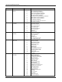
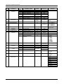
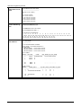
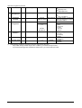
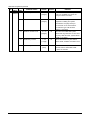
REVISION HISTORY
ISSUE
DATE
DESCRIPTION
ISSUE 1.0
1999. 08
Initial Release
ISSUE 1.1
1999.10
Revised Admin Programming.
ISSUE 1.2
2000.12
1. Nation Specific Document for UK is modified. BASIC III-Plus
version S/W is released and some new features are implemented.
ISSUE 2.0
2001.03
1. The BASIC III features are included in the Feature Description &
Admin Programming parts. Separated section of BASIC III Features
is removed.
2. The BASIC III features are as follows;
- In Circular/Terminal hunt group, an incoming call will continued to be
routed until every station in the group has been tried.
- When a Circular/Terminal/UCD group member presses DND button while
ringing, the ring at the station stops and the next available member starts
ringing.
- When a CO line call is transferred to hunt group, the transferred CO line
call will follow the hunt process.
- Intercom call and CO line transfer to ring group are available.
- DID Day/Night Destination
- DID/DISA CO line calls and internal calls, made to the busy station in call
forward to DVIB, is routed to DVIB.
- LCR feature is also applied after seizing CO line by pressing CO key or
LOOP key.
- DKTU user can have multiple LOOP keys.
- Night DVU (Main Menu 5 – Terminal Menu 7)
- Music on Camp-on (Main Menu 5 – Terminal Menu 8)
ISSUE 2.1
2001.06
1. Revised “Numbering Plan”
2. Revised “Call Forward”
-
Incoming CO Line Off-Net, Off-Net
ISSUE 2.2
2001.11
Added GDC-340H wireless terminal
ISSUE 3.0
2002. 05
1. Features are added in software version 3.0
Admin password, Auto-delete of DVIB message, Day/Night mode change
(Automatic), Dial by name, Delayed DISA, Direct call pick-up,
DVU announcement with station off-net call forward,
DVU announcement with ring group, Hunt group overflow,
SMDR records save, Station name display,
To leave DVIB message by [CALLBK] key during ICM call,
Auto Call Number Redial, Call Park, CCR for DID or DISA,
CLI name display/print, CO line Queuing, Station Language change,
DID(MSN) day/night destination, Keypad facility service, Trunk to
Trunk(CO to CO) transfer, DVU management and Normal ring to DVIB
5
GDK-20W Programming Manual
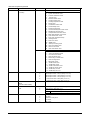
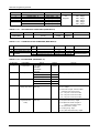
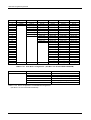
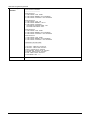
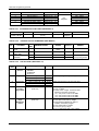
ISSUE
DATE
ISSUE 3.0
2002.05
DESCRIPTION
2. Admin programs for software version 3.0 are added.
-. Added Admin Program in Station Base Program( Main Menu 2)
CLI Name Display, Keypad Facility
-. Changed Admin Program in Station Base Program( Main Menu 2)
Language Code
-. Added Admin Program in CO Line Base Program( Main Menu 3)
CPT Tone Detect
-. Added Admin Programs in System Base Program( Main Menu 5)
SMDR Save, Record in Detail, CCR Table, Admin Password, DVU setting,
Weekly Time Table, ACNR Tone Cadence
-. Added Admin Program in System Timers Program( Main Menu 6)
Call Park Recall Timer, Normal Ring to DVIB Timer, CCR Inter Digit
Timer, DISA Delay Timer, ACNR Pause Timer, ACNR Delay Timer, ACNR
Tone Detect Timer, ACNR` No Answer Timer, ACNR
Retry Counter, ACNR Retry No Tone
-. Added Admin Program in HUNT Group/Voice Mail Program( Main Menu
11)
- Overflow Destination, Overflow Timer are added for Cir/Term, UCD, VM
and Ring Group.
Ring Announcement Timer is added in Ring Group
6
GDK-20W Programming Manual
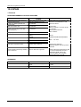
CONTENTS
1. INTRODUCTION......................................................................................................................................................11
1.1 SYSTEM CAPACITIES …………………………………………………………………………………….………….11
1.2 NUMBERING PLAN…………………………………………………………………..... ……………………………12
1.3 BASIC AND EXTENDED NUMBERING PLANS …………………………………………………………………. 14
1.4 LCD MONTHS ……………………………………………………………………………………………………….. 14
1.5 AUDIBLE SIGNALS …………………………………………………………………………………………………. 15
1.6 FREQUENCIES AND TONES ……………………………………………………………………………………… 16
1.7 GDK-20W CONFIGURATION ……………………………………………………………………………………… 18
1.8 GDK-20WATION CONFIGURATION WITH LKD 2B ……………………………………………………………. 18
1.9 MAXIMUM NUMBER OF STATIONS IN GDK-20W : 34PORTS ………………………………………………. 18
1.10 MAXIMUM NUMBER OF CO LINES IN GDK-20W : 8PORTS ………………………………………………… 18
1.11 MAXIMUM NUMBER OF PORTS (STATION / CO) IN GDK-20W : 38PORTS ………………………………. 19
1.12 WIRELESS CELL / TERMINAL CONFIGURATION …………………………………………………………….. 19
1.13GAIN CONTROL (SYSTEM BASE (MAIN MENU 5 - SUB MENU 14) ………………………………………… 19
2. SYSTEM FEATURES ..............................................................................................................................................23
ADMIN PASSWORD ..................................……………………………………………………………………………….. 23
ALARM SIGNAL REPEATING .................................................................................................................................24
AUDIO BEARER CAPABILITY 3.1KHZ ....................................................................................................................25
AUTO-DELETE OF DVIB MESSAGES ....................................................................................................................25
AUTOMATIC FAX TRANSFER ................................................................................................................................26
AUTOMATIC PRIVACY ...........................................................................................................................................27
BACKGROUND MUSIC (BGM) ................................................................................................................................27
BATTERY BACK-UP, MEMORY ..............................................................................................................................28
BUSY LAMP FIELD (BLF) ........................................................................................................................................29
CONFERENCE ........................................................................................................................................................29
Conference: Add-on 29
Conference: Multi-line 30
Conference: Unsupervised 30
DAY/NIGHT MODE CHANGE - AUTOMATIC ..........................................................................................................31
DATA LINE SECURITY & BRARER CAPABILITY 3.1 KHZ ......................................................................................32
DIAL BY NAME - SPEED DIAL AND ICM CALL........................................................................................................33
DIFFERENTIAL RING ( DIGITAL KEYSET ONLY)...................................................................................................35
DELAYED DISA .......................................................................................................................................................36
DIRECT CALL PICK UP ...........................................................................................................................................37
DOOR OPEN ...........................................................................................................................................................38
DVIB .........................................................................................................................................................................38
DVIB - SYSTEM GREETINGS & PROMPTS.............................................................................................................38
DVIB – VOICE ANNOUNCEMENT WITH DID/DISA LINE........................................................................................40
DVIB – USER GREETING & VOICE MESSAGE WAIT ............................................................................................42
DVIB – VOICE ANNOUNCEMENT WITH STATION GROUP...................................................................................46
DVIB - VOICE ANNOUNCEMENT WITH STATION OFF-NET CALL FORWARD ....................................................46
DVIB – MOH.............................................................................................................................................................47
DVIB - DVU ANNOUNCEMENT WITH RING GROUP..............................................................................................48
HEADSET COMPATIBILITY ....................................................................................................................................49
HUNT GROUP OVERFLOW ....................................................................................................................................49
HUNT GROUP – CIRCULAR, TERMINAL, UCD AND RING ....................................................................................50
IDLE LINE SELECTION (WARM LINE ONLY) .........................................................................................................53
INTERCOM (ICM) BOX ............................................................................................................................................54
LOUD BELL CONTROL (LBC) .................................................................................................................................55
PAGE .......................................................................................................................................................................55
PAGE - Internal Zone 55
PAGE - All Call Paging 56
PAGE - Meet Me Page 57
PAGE - PAGE ACCESS RESTRICTION ..................................................................................................................57
PAGE - EXTERNAL PAGING...................................................................................................................................57
PICK-UP...................................................................................................................................................................58
STATION MESSAGE DETAIL RECORDING (SMDR) .............................................................................................59
SMDR RECORDS SAVE..........................................................................................................................................60
STATION NAME DISPLAY.......................................................................................................................................62
SPEAKER PHONE...................................................................................................................................................62
STATION LANGUAGE CHANGE.............................................................................................................................63
TWO-WAY RECORDING.........................................................................................................................................64
7
GDK-20W Programming Manual
WAKE-UP ALARM ...................................................................................................................................................65
VOICE MAIL GROUP ...............................................................................................................................................66
3. INTERCOM FEATURES..........................................................................................................................................67
AUTO RELEASE OF [MON] BUTTON .....................................................................................................................67
AUTOMATIC SPEAKER ACTIVATION ....................................................................................................................67
CALL ANNOUNCE W/HF ANSWER BACK ..............................................................................................................68
CALL ANNOUNCE W/PRIVACY ..............................................................................................................................68
CALL FORWARD .....................................................................................................................................................68
Call Forward, Unconditional
68
Call Forward, Busy/ No Answer
69
Call Forward, Off-Net 70
Call Forward, Incoming CO Line Off-Net 71
CALL WAITING (CAMP-ON) ....................................................................................................................................72
DAY/NIGHT CLASS-OF-SERVICE ..........................................................................................................................73
DO-NOT-DISTURB (DND) .......................................................................................................................................74
ICM DIAL-TONE REORDER, ICM FLASH ...............................................................................................................74
ICM SIGNAL MODE SELECTION ............................................................................................................................75
INTERCOM CALL ....................................................................................................................................................76
MESSAGE WAIT/CALL-BACK.................................................................................................................................76
MESSAGE WAIT REMINDER SIGNAL ....................................................................................................................77
MICROPHONE MUTE..............................................................................................................................................78
ON-HOOK DIALING .................................................................................................................................................78
TO LEAVE DVIB MESSAGE BY [CALLBK] KEY DURING ICM CALL ......................................................................79
4. CO LINE FEATURES ..............................................................................................................................................82
AUTO CALL NUMBER REDIAL(ACNR) ..................................................................................................................82
AUTOMATIC HOLD .................................................................................................................................................84
AUTOMATIC PAUSE INSERTION...........................................................................................................................84
CALL PARK..............................................................................................................................................................85
CALL FORWARD - PRESET....................................................................................................................................86
CCR(CUSTOM CALL ROUTING) FOR DID OR DISA ..............................................................................................87
CLI NEME DISPLAY/PRINT.....................................................................................................................................88
CO LINE ACCESS....................................................................................................................................................90
CO LINE TRANSFER ...............................................................................................................................................91
CO LINE GROUPS...................................................................................................................................................92
CO LINE RELEASE GUARD TIME...........................................................................................................................92
CO LINE QUEUING..................................................................................................................................................93
DID(MSN) DAY/NIGHT DESTINATION ...................................................................................................................94
DIRECT INWARD SYSTEM ACCESS (DISA) ..........................................................................................................94
FLASH, CO LINE DIAL-TONE REORDER ...............................................................................................................95
FLEXIBLE CO LINE ACCESS ..................................................................................................................................96
FLEXIBLE CO LINE RING ASSIGNMENT ...............................................................................................................97
FLEXIBLE CO LINE RING DETECTION ..................................................................................................................97
HOLD - EXCLUSIVE W/RECALL .............................................................................................................................97
HOLD - SYSTEM W/RECALL...................................................................................................................................98
HOLD PREFERENCE ..............................................................................................................................................99
INCOMING CO RING ASSIGNMENT TO HUNT GROUP ........................................................................................99
LCR (LEAST COST ROUTING) .............................................................................................................................100
LCR WITH DISA CO ACCESS ...............................................................................................................................102
MULTIPLE LOOP KEYS.........................................................................................................................................102
MUSIC ON HOLD (MOH) .......................................................................................................................................103
NIGHT DVU............................................................................................................................................................104
OFF-HOOK SIGNALING, CO CALLS.....................................................................................................................105
PREFERRED LINE ANSWER (PLA) ......................................................................................................................105
PULSE/TONE CO LINE SIGNALING .....................................................................................................................105
SPEED DIAL ..........................................................................................................................................................106
Special Speed Dial Commands
106
Speed Dial - Last Number Redial (LNR) 107
Speed Dial - Station 107
Speed Dial - System
108
TRUNK TO TRUNK (CO TO CO) TRANSFER .......................................................................................................109
UNIVERSAL NIGHT ANSWER (UNA)....................................................................................................................110
5. ATTENDANT FEATURES .....................................................................................................................................112
ATTENDANT ASSIGNMENT .................................................................................................................................112
ATTENDANT CLOCK SET.....................................................................................................................................112
8
GDK-20W Programming Manual
ATTENDANT RECALL ...........................................................................................................................................113
DATE/TIME DISPLAY FORMAT CONTROL ..........................................................................................................113
DAY/NIGHT MODE SERVICE (MANUAL)..............................................................................................................114
DVU MANAGEMENT(ONLY ATTENDANT) ..........................................................................................................114
NORMAL RING TO DVIB (ONLY BY ATTENDAN) ................................................................................................117
TO SET CURRENT TIME 1 HOUR EARLY/LATE ..................................................................................................118
WAKEUP FAIL RING TIME OUT............................................................................................................................118
6. SLT FEATURES ....................................................................................................................................................120
BROKERS CALL & CONFERENCE .......................................................................................................................120
CALL FORWARD ...................................................................................................................................................120
CALL PICK-UP.......................................................................................................................................................121
CALL WAITING ......................................................................................................................................................121
CO FLASH (SLT)....................................................................................................................................................122
CO LINE ACCESS..................................................................................................................................................122
CO LINE TRANSFER .............................................................................................................................................123
DIRECT CO LINE RINGING...................................................................................................................................124
DO NOT DISTURB.................................................................................................................................................124
ICM RINGDOWN (HOT/WARM LINE)....................................................................................................................125
INTERCOM CALLING ............................................................................................................................................126
LAST NUMBER REDIAL ........................................................................................................................................126
MESSAGE WAIT/CALL BACK ...............................................................................................................................127
PAGING ACCESS..................................................................................................................................................128
STATION SPEED DIAL ..........................................................................................................................................128
SYSTEM SPEED DIAL...........................................................................................................................................129
7. ISDN FEATURES ..................................................................................................................................................130
THE BASIC FEATURES OF ISDN DEVICE(S - INTERFACE)................................................................................130
THE FEATURES OF ISDN CO LINE(T - INTERFACE) ..........................................................................................132
ISDN - CALL HOLD / RETRIVE ..............................................................................................................................134
ISDN - BROKER CALL ..........................................................................................................................................135
ISDN - 3 PARTY CONFERENCE ...........................................................................................................................135
ISDN - CLI WITH NO ANSWER(CLI MESSAGE WAIT)..........................................................................................136
ISDN LOOP BACK ON/OFF ...................................................................................................................................138
ISDN - TRANSPARENCY ......................................................................................................................................138
ZERO INSERTION IN THE PRESENTATION ON LCD..........................................................................................139
8. SUBSCRIPTION/DE-SUBSCRIPTION(WIRELESS TERMINAL)..........................................................................140
SYSTEM ID ............................................................................................................................................................140
AUTHENTICATION CODE.....................................................................................................................................141
USER SUBSCRIPTION..........................................................................................................................................142
USER DESUBSCRIPTION.....................................................................................................................................143
HANDOVER...........................................................................................................................................................144
OUT OF RANGE INDICATION...............................................................................................................................145
LOW BATTERY......................................................................................................................................................145
9. WIRELESS TERMINAL FEATURES.....................................................................................................................146
CALL FORWARD ...................................................................................................................................................146
CALL PICK-UP.......................................................................................................................................................146
CALL WAITING ......................................................................................................................................................147
CO FLASH .............................................................................................................................................................147
CO LINE ACCESS..................................................................................................................................................147
CO LINE TRANSFER .............................................................................................................................................148
DIRECT CO LINE RINGING (WIRELESS TERMINAL) ..........................................................................................149
DO NOT DISTURB (WIRELESS TERMINAL) ........................................................................................................149
ICM RINGDOWN ...................................................................................................................................................150
INTERCOM CALLING ............................................................................................................................................151
LAST NUMBER REDIAL ........................................................................................................................................151
MESSAGE WAIT/CALL BACK ...............................................................................................................................152
PAGING ACCESS..................................................................................................................................................152
STATION SPEED DIAL ..........................................................................................................................................153
SYSTEM SPEED DIAL...........................................................................................................................................154
STATION NUMBER RECOVERY ..........................................................................................................................154
10. PC RELATED FEATURES ..................................................................................................................................155
PC ADMIN - LOCAL ...............................................................................................................................................155
PC ADMIN - REMOTE............................................................................................................................................155
SOFTWARE UPGRADE - LOCAL..........................................................................................................................156
9
GDK-20W Programming Manual
SOFTWARE UPGRADE - REMOTE ......................................................................................................................157
11.ADMIN PROGRAMMING......................................................................................................................................159
11.1GENERAL .......................................................................................................................................................159
11.1.1 INTRODUCTION ……………………………………………………………………………………………… 159
11.1.2 TO ENTER THE PROGRAMMING MODE …………………………………………………………………. 159
11.1.3 HOW TO PROGRAM …………………………………………………………………………………………. 159
11.1.4 BUTTON DEFINITION ………………………………………………………………………………………... 160
11.1.5 ADMIN PROGRAMMING INDEX ……………………………………………………………………………. 161
11.1.6 DEFAULT VALUES …………………………………………………………………………………………… 163
11.2 PROGRAMMING............................................................................................................................................174
11.2.1 DATABASE INITIALIZATION (MAIN MENU 1) …………………………………………………………….. 174
11.2.2 STATION BASE PROGRAM (MAIN-MENU 2) ……………………………………………………………... 175
11.2.3 CO LINE PROGRAMMING (MAIN-MENU 3) ………………………………………………………………… 184
11.2.4 ISDN PROGRAM (MAIN-MENU 4) …………………………………………………………………………… 189
11.2.5 SYSTEM BASE PROGRAMMING (MAIN-MENU 5) ……………………………………………………….. 194
11.2.6 SYSTEM TIMER PROGRAMMING (MAIN-MENU 6) ………………………………………………………. 208
11.2.7 TOLL TABLE (MAIN-MENU 7) ………………………………………………………………………………… 211
11.2.8 AUTHORIZATION CODE TABLE (MAIN-MENU 8) …………………………………………………………. 212
11.2.9 FLEXIBLE NUMBERING PLAN (MAIN-MENU 9) …………………………………………………………… 213
11.2.10 LCR PROGRAM (MAIN-MENU 10) ………………………………………………………………………….. 214
11.2.11 HUNT GROUP PROGRAM / VM TABLE (MAIN-MENU 11) ………………………………………………. 217
11.2.12 DATABASE PRINT (MAIN-MENU 12) ……………………………………………………………………….. 220
12. NATION SPECIFIC DOCUMENT ………………………………………………………………………………............ 228
12.9 SPAIN …………………………………………………………………………………………………………………. 228
10
GDK-20W Programming Manual
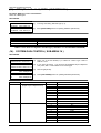
1. INTRODUCTION
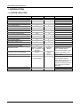
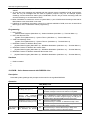
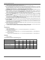
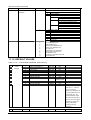
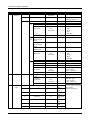
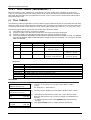
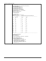
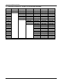
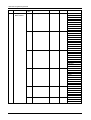
1.1 SYSTEM CAPACITIES
ITEM
FP II
GDK-20W
Max No of Stations
Max No of CO lines
Max DSS/DLS Console per station
67
34
2
34
8
0
No of CO line Groups
9
4
No of Attendants
No of Internal Page Zones
5
5
1
2
200
20
79
20
100 (Option 1900)
2
2
2
8
System : 3 Minutes
User : 17 Minutes 30
Seconds
250 ea.
500
2
0
1
1
2
68 Minutes
(Basic)
No of System Speed Dial Bins
No of Station Speed Dial Bins Per Station
No of SMDR Records
No of External Relays
No of Power Failure Circuit
Number of Automatic Fax Transfer
Number of DVIB
Number of Channel / DVIB
Max Record Time
Number of User Voice Messages
Default Voice Data
Battery Backup Voice Messages
Prompts
System
Announcements
Number of Station Group
Max Number of Member in Group
8
32 Stations
11
200 ea.
(Basic)
Prompts
All the messages
4
10 Stations
REMARK
Above version 3.0
Additional 70-minute record
time is available with the
optional board installed. Total
number of messages is 400
with the option.
All the messages are saved
with the backup switch on.
When backup switch is set off,
only system greetings and
prompts are saved. Recorded
user messages are deleted
after reset.
GDK-20W Programming Manual
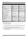
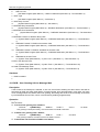
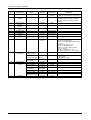
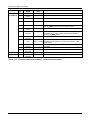
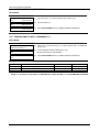
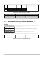
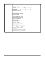
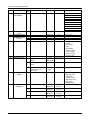
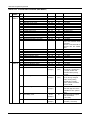
1.2 NUMBERING PLAN*1
FEATURES
Station Intercom Number
CO Line Access ,Group
CO Line Access ,Individual
Retrieve a Held CO Line - Individual
Retrieve a Held CO Line
Attendant
CO Line Access, First Accessible Group
Call Waiting (Camp-on)
Page, All Call
Page, Internal Zone
External Page
Page, Meet Me
SLT, Last Number Redial (LNR)
SLT, DND
SLT, Call Forward
SLT, Speed Dial, Program
SLT, Speed Dial, Access
Alarm Reset
Pick-Up
UNA
2/8 Btn, Message Wait / Call Back - Request
2/8 Btn, Message Wait - Answer
SLT, CO Flash
SLT, Call Waiting (Camp-on)
SLT, Message Wait / Call Back
SLT, CO Hold
Attendant, Clock Set
Admin Program Start
Attendant, Date Format Change
Attendant, Time Format Change
Attendant, WHTU*4 Subscribe/ De-subscribe
Version Display
Wake-Up Program
Wake-Up Cancel
ICM Signal Mode - HF/TN/PV
Differential Ring
COLR/CLIP Key
BGM
Loop Key
Call Wait Key
SPEED Key
CONF Key
CALL BK Key
DND Key
MUTE Key
REDIAL Key
Last Number Redial (LNR)
Door Open
CODES
100 - 133
81-84
881-888
8#1 - 8#8
8##
0
9
*
#0
#1 - #2
#3
#6, [HOLD/SAVE]
52
53
54
55
58
65
66
69
[PGM]+56
57
Hook Flash + 51
Hook Flash + *
Hook Flash + 56
Hook Flash + 59
[PGM]+#1
[PGM]+*#
[PGM]+*5
[PGM]+*6
[PGM]+##
[PGM]+40
[PGM]+41
[PGM]+42
[PGM]+49 + 1/2/3
[PGM]+50 + 1/2/3/4
[PGM]+58
[PGM]+73
[PGM]+84
[PGM]+85
[PGM]+90
[PGM]+91
[PGM]+92
[PGM]+93
[PGM]+95
[PGM]+97
[SPEED]+*, [REDIAL]
#*1-2
12
REMARKS
Programmable 100 - 499
SLT
SLT
ICM Busy Tone, B
B*2*3
B
B (#6)
SLT
SLT, WHTU
SLT, WHTU
SLT
SLT
B
B
B
2/8 Button
2/8 Button
SLT
SLT, ICM Busy Tone
SLT
SLT
Attendant
100
Attendant
Attendant
Attendant
Station, Attendant
Station, Attendant
Keyset only
Keyset only
Note 5)
B
B Only
B Only
B Only, 2/8 Button Only
B Only, 2/8 Button Only
B Only, 2/8 Button Only
B Only, 2/8 Button Only
B Only, 2/8 Button Only
B Only, 2/8 Button Only
GDK-20W Programming Manual
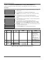
FEATURES
Call Park
Direct Call Pick Up
Station Language Code Change
Speaker/Headset Button
SMDR PRINT
SMDR DELETE
ABORT PRINTING
DVIB- Date & Time Order
DVIB- Retrieval Order
DVIB- Check Time Status
DVIB- Check Number Status
DVIB- Delete Station Message
DVIB – Recording System Announcements
DVIB – Recording User Greeting
(With DVIB Station Forward Timer)
DVIB – Recording User Greeting
(With fixed 4 seconds timer)
Call Forward to DVIB Port
(With DVIB Station Forward Timer)
Call Forward to DVIB Port
(With fixed 4 seconds timer)
DVIB – Delete User Greeting
Call Forward – Cancel
To Set Current Time - 1 Hour early
To Set Current Time - 1 Hour late
Station Pilot Number
VM MSG Wait Enable
VM MSG Wait Disable
ISDN Supplementary HOLD
ISDN Supplementary CONF
Two Way Recording
CODES
REMARKS
601-606
7
[PGM]+51
[PGM]+57
[PGM]+*81
[PGM]+*82
[PGM]+*83
[PGM] + *71
[PGM] + *72
[PGM] + *73
[PGM] + *74
[PGM] + *76
[TRANS/PGM]+#4
[MON]+[DND/FOR]+7+#
B
B
B only
Attendant
Attendant
Attendant
Attendant
Attendant
Attendant
Attendant
Attendant
Attendant
Note 1)
-
Note 1)
[MON]+[DND/FOR]+7
Note 2)
-
Note 2)
[MON]+[DND/FOR]+7+*
[MON]+[DND/FOR]+#
[TRANS/PGM]+*1
[TRANS/PGM]+*2
61-64
*8
*9
[TRANS/PGM]+*75#
[TRANS/PGM]+*77#
[TRANS/PGM]+#4
Note 3)
Note 4)
Attendant
Attendant
Button Only
Button Only
Button Only
*1: Numbering Plan can be changed according to nation.
*2: B - Button program is available.
*3: If a flexible button is programmed as a certain function with the same function already programmed in another
flexible button, then the old one is cleared.
*4: WHTU: Wireless Handset Telephone Unit.
Note 1)
Note 2)
Call Forward to DVIB is activated after recording User Greeting. When user dials forward type “7” and if there is
recorded User Greeting already, then user may not record User Greeting again and recorded User Greeting is
used.
User Greeting should be recorded before Call Forward to DVIB port. When user hangs up after the forward type
“7” and if there is no recorded User Greeting, then forward is not activated.
Note 3) If a station is forwarded to DVIB port, Call Forward is canceled after deleting User Greeting.
Note 4)
Note 5)
Only Call Forward to DVIB port is canceled and recorded User Greeting is not deleted. User can delete User
Greeting by [MON]+[DND/FOR]+7+*.
“COLR/CLIR” has a double function. It is used to restrict both for the CLI for outgoing call and Connected Line
number for incoming call.
13
GDK-20W Programming Manual
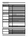
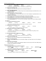
1.3 BASIC AND EXTENDED NUMBERING PLANS
FEATURES
BASIC
EXTENSION
Station Intercom Number
10-49 or 100 - 499
10-99 or 100-999
CO Line Access ,Group
CO Line Access, Loop
CO Line Access ,Individual
Retrieve a Held CO Line - Individual
Retrieve a Held CO Line
Attendant
CO Line Access, First Accessible Group
Call Waiting (Camp-on)
Page, All Call
Page, Internal Zone
External Page
Page, Meet Me
SLT, Last Number Redial (LNR)
SLT/WHTU, DND
SLT/WHTU, Call Forward
SLT, Speed Dial, Program
SLT, Speed Dial, Access
Alarm Reset
Pick-Up
UNA
2/8 Btn, Message Wait / Call Back Request
2/8 Btn, Message Wait - Answer
SLT, CO Flash
SLT, Call Waiting (Camp-on)
SLT, Message Wait / Call Back
SLT, CO Hold
Station Pilot Number
Door Open
81-84
85
881-888
8#1 - 8#8
8##
0
9
*
#0
#1 - #2
#3
#6, [HOLD/SAVE]
52
53
54
55
58
65
66
69
[PGM] + 56
*81-*84
*85
*881-*888
*8#1 - *8#8
*8##
0
*9
*
#0
#1 - #2
#3
#6, [HOLD/SAVE]
*52
*53
*54
*55
*58
*65
*66
*69
[PGM] + #56
57
Hook Flash + 51
Hook Flash + *
Hook Flash + 56
Hook Flash + 59
61-64
#*1-2
*57
Hook Flash + #51
Hook Flash + *
Hook Flash + #56
Hook Flash + #59
*61 - *64
#*1 - #*2
REMARKS
2 or 3 digit station
numbers by Admin
SLT
SLT
ICM Busy Tone, B
B*1
B
B (#6)
SLT
SLT/WHTU*2
SLT/WHTU
SLT
SLT
B
B
B
2/8 Button
2/8 Button
SLT
SLT, ICM Busy Tone
SLT
SLT
*1: B - Button program is available.
*2: WHTU - Wireless Handset Telephone Unit
Remark) Extension Numbering Plan will be selected by Admin Program.
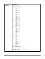
1.4 LCD MONTHS
NATION
1
2
3
4
5
6
7
8
9
10
11
12
English
Italian
Finnish
Danish
Dutch
Swedish
Norwegian
German
Spanish
JAN
GEN
01
JAN
JAN
JAN
JAN
FEB
FEB
02
FEB
FEB
FEB
FEB
MAR
MAR
03
MAR
MRT
MAR
MAR
APR
APR
04
APR
APR
APR
APR
MAY
MAG
05
MAJ
MEI
MAJ
MAI
JUN
GIU
06
JUN
JUN
JUN
JUN
JUL
LUG
07
JUL
JUL
JUL
JUL
AUG
AGO
08
AUG
AUG
AUG
AUG
SEP
SET
09
SEP
SEP
SEP
SEP
OCT
OTT
10
OKT
OKT
OKT
OKT
NOV
NOV
11
NOV
NOV
NOV
NOV
DEC
DIC
12
DEC
DEC
DEC
DES
01
02
03
04
05
06
07
08
09
10
11
12
ENE
FEB
MAR
ABR
MAY
JUN
JUL
AGO
SEP
OCT
NOV
DIC
* Finnish example of date:
30-07-98 (In case of DDMMYY order, System Base Program(Main Menu5) - LCD Display Mode (Sub Menu4)
14
GDK-20W Programming Manual
1.5 AUDIBLE SIGNALS
TONE / RING
Alarm Ring, Continuous
Alarm Ring, Single
All Call Page Tone
Busy Tone
CO Ring Back Tone
CO Ring
CADENCE
Australia
Finland
EU
Spain
Sweden
Denmark
Others
New Zealand
Others
Finland
Italy
Others
LCR Dummy CO Dial Tone
Confirm Tone
DND Tone
Dial Tone
Error Tone
HFTB Warning Tone
Intercom Ring
Reminder Tone
Ring Back Tone
Finland
EU
Others
Australia
Finland
Italy
Spain
Sweden
Others
Finland
Italy
Others
Australia
New Zealand
Denmark
Finland
EU
Italy
Netherlands
Norway
Spain
Sweden
Others
0.2 sec ON / 0.2 sec OFF Repeat
1 sec ON
1 sec ON
0.35 sec ON / 0.35 sec OFF Repeat
0.3 sec ON / 0.3 sec OFF Repeat
0.2 sec ON / 0.2 sec OFF Repeat
0.25 sec ON / 0.25 sec OFF Repeat
0.5 sec ON / 0.5 sec OFF Repeat
1 sec ON / 3 sec OFF Repeat
1 sec ON / 2 sec OFF Repeat
1 sec ON / 4 sec OFF Repeat
0.4 sec ON / 0.4 sec OFF / 0.4 sec ON / 2 sec OFF Repeat
Continuous
1.2 sec ON
0.2 sec ON / 0.2 sec OFF / 0.2 sec ON / 0.2 sec OFF / 0.2 sec ON
/ 0.5 sec OFF Repeat
0.2 sec ON / 0.3 sec OFF / 0.2 sec ON / 0.3 sec OFF / 0.2 sec ON
/ 0.8 sec OFF Repeat
0.2 sec ON / 0.3 sec OFF / 0.7 sec ON / 0.8 sec Off Repeat
Continuous
2.5 sec ON / 0.5 sec OFF Repeat
0.2 sec ON / 0.2 sec OFF Repeat
0.6 sec ON / 1 sec OFF Repeat
0.25 sec ON / 0.75 sec OFF Repeat
0.25 sec ON / 0.25 sec OFF Repeat
0.2 sec ON / 0.2 sec OFF 3 Times
0.6 sec ON / 0.2 sec OFF / 0.6 sec ON / 4 sec OFF Repeat
0.6 sec ON / 0.2 sec OFF / 0.2 sec ON / 4 sec OFF Repeat
0.8 sec ON / 2.4 sec OFF Repeat
0.5 sec ON / 0.5 sec OFF 3 Times
0.4 sec ON / 0.2 sec OFF / 0.4 sec ON / 2 sec OFF Repeat
1 sec ON / 4 sec OFF Repeat
1.5 sec ON / 3 sec OFF Repeat
1 sec ON / 5 sec OFF Repeat
1 sec ON / 2 sec OFF Repeat
- SLT
SLT RING
SLT CO Ring
SLT Intercom Ring
CADENCE
Finland
Italy
New Zealand
Spain
Others
Finland
Italy
New Zealand
Spain
1 sec ON / 4 sec OFF Repeat
0.4 sec ON / 0.2 sec OFF / 0.4 sec ON / 2 sec OFF Repeat
1 sec ON / 3 sec OFF Repeat
0.4 sec ON / 0.2 sec OFF / 0.4 sec ON / 4 sec OFF Repeat
0.4 sec ON / 0.2 sec OFF / 0.4 sec ON / 4 sec OFF Repeat
0.6 sec ON / 0.2 sec OFF / 0.2 sec ON / 4 sec OFF Repeat
1 sec ON / 2 sec OFF Repeat
0.4 sec ON / 0.2 sec OFF / 0.4 sec ON / 3 sec OFF Repeat
Others
1 sec ON / 4 sec OFF Repeat
15
GDK-20W Programming Manual
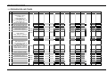
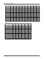
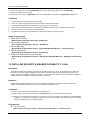
1. 6 FREQUENCIES AND TONES
NO
TONE / RING
1
1000Hz
1020Hz
425Hz
-
3
DIFFERENTIAL RING - 1
REMINDER TONE (4)
CO RING (19)
INTERCOM RING (20)
ALARM RING (21)
CALL WAIT BURST RING (22)
QUEUE RING (23)
SINGLE ALARM RING (24)
DIAL TONE (11)
DIAL WARNING TONE (12)
CO RING BACK TONE (17)
425Hz
-
4
RING BACK TONE (5)
425Hz
-
5
BUSY TONE (1)
425Hz
-
6
620Hz
-
7
ERROR TONE (2)
DND TONE (3)
CONF TIMEOUT TONE (13)
DISSUATION TONE (16)
Reserved
425Hz
-
8
COL HOLD TONE (15)
425Hz
-
9
ALL CALL PAGE TONE (6)
ICM PAGE TONE (7)
HFTB WARNING TONE (8)
OHVA TONE (14)
CONFIRMATION TONE (9)
SINGLE ERROR TONE (10)
ADMIN ERROR TONE (18)
LCR Dummy CO Dial Tone
950Hz
-
1400Hz
-
2
10
11
DEFAULT
425Hz
350Hz
1260Hz
1633Hz
13
Reserved
(DUAL HOWLING TONE)
DIFFERENTIAL RING - 2
890Hz
910Hz
14
DIFFERENTIAL RING - 3
1260Hz
15
DIFFERENTIAL RING - 4
800Hz
16
Reserved
480Hz
-
17
Reserved
400Hz
-
18
Reserved
620Hz
-
19
Reserved
770Hz
-
12
FINLAND
ITALY
NETHERLANDS
NEW ZEALAND
SWEDEN
480Hz
425Hz
425Hz
350Hz
400Hz
-
1000Hz
425Hz
425Hz
-
-
425Hz
-
425Hz
-
350Hz
440Hz
425Hz
-
UK
-
-
350Hz
440Hz
400Hz
-
440Hz
480Hz
400Hz
440Hz
440Hz
480Hz
400Hz
-
480Hz
620Hz
400Hz
-
1400Hz
-
-
425Hz
-
400Hz
-
1280Hz
620Hz
-
820Hz
770Hz
-
16
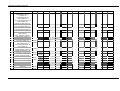
GDK-20W Programming Manual
NO
TONE / RING
1
DIFFERENTIAL RING - 1
REMINDER TONE (4)
CO RING (19)
INTERCOM RING (20)
ALARM RING (21)
CALL WAIT BURST RING (22)
QUEUE RING (23)
SINGLE ALARM RING (24)
DIAL TONE (11)
DIAL WARNING TONE (12)
RING BACK TONE (5)
COL RING BACK TONE (17)
BUSY TONE (1)
1000Hz
1020Hz
425Hz
-
425Hz
-
425Hz
-
620Hz
-
6
ERROR TONE (2)
DND TONE (3)
CONF TIMEOUT TONE (13)
DISSUATION TONE (16)
Reserved
425Hz
-
7
COL HOLD TONE (15)
425Hz
-
8
ALL CALL PAGE TONE (6)
ICM PAGE TONE (7)
HFTB WARNING TONE (8)
OHVA TONE (14)
CONFIRMATION TONE (9)
SINGLE ERROR TONE (10)
ADMIN ERROR TONE (18)
LCR Dummy CO Dial Tone
950Hz
-
1400Hz
-
2
3
4
5
9
10
DEFAULT
425Hz
350Hz
1260Hz
1633Hz
12
Reserved
(DUAL HOWLING TONE)
DIFFERENTIAL RING - 2
890Hz
910Hz
13
DIFFERENTIAL RING - 3
1260Hz
1280Hz
14
DIFFERENTIAL RING - 4
800Hz
820Hz
15
Reserved
480Hz
-
16
Reserved
400Hz
-
17
Reserved
620Hz
-
18
Reserved
770Hz
-
11
SPAIN
425Hz
EU
KOREA
-
17
CIS
GDK-20W Programming Manual
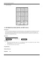
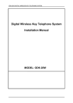
1. 7 GDK-20W CONFIGURATION
Basic
STA
Basic Base
Station
WTIB SLOT
Base Station
4 key + 2 slt
(4 port with
2B )
1 Base Station
(4 Simultaneous
Wireless Calls )
2 Base Station
(8 Simultaneous
Wireless Calls )
CO SLOT1
CO SLOT2
LCOB /LCOB2/STIB/STIB2
LCOB : 2LCO
LCOB2 :4LCO
STIB : 1T0
STIB2 : 1T0 + 1T0/1S0
TOTAL
STA : 100-103 (DKTU)
104-105(SLT)
STA : 106-109(LKD 2B DKTU
In primary 100-103)
WHTU :110-129
CO : CO1 – CO8
or
CO : CO1-CO4 and
4 S0 Station (130-133)
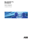
1.8 GDK-20W STATION CONFIGURATION WITH LKD 2B
BASIC
4 LKD 2B + 2 slt
1)
2)
3)
4)
DEFAULT STA NUMBER
100 -105
106 -109
110 -129
130 -133
: 4 LKD 2B Primary devices and 2 slts
: Secondary devices of 100-103 (LKD 2B DKTU)
: Wireless Telephones
: 4 S0 stations in two STIB2 SLOTs
LKD 2B occupies 4 station numbers, one for the Primary device and the other for the Secondary device. It can
be connected to Basic 4 DKT ports.
If LKD 2B is connected to any 4 DKT port in MBU, it occupies only 1 station number, for the Primary device. It
means that the station can not have any Secondary device even if there is DTIU or SLIU for the Secondary device
in it.
LKD 2B without either DTIU or SLIU(Basic LKD 2B) occupies 1 station number, for the Primary device.
Note: DTIU, SLIU are the sub boards in LKD 2B for the Secondary device DKTU or SLT.
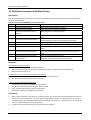
1.9 MAXIMUM NUMBER OF STATIONS IN GDK-20W : 34 PORTS
NUMBER OF PORTS
DEFAULT STATION NUMBER
DESCRIPTION
6
100-105
4 Basic DKT ports and 2 Basic slt ports
4
106-109
4 Secondary devices for 4 basic DKT ports
20
110-129
4
130-133
Registrable Max. Wireless Telephones
(Max. Simultaneous Wireless Call : 12 )
4 S0 stations in STIB second S0
( When STIB2 is installed in SLOT2 and 3)
1.10 MAXIMUM NUMBER OF CO LINES IN GDK-20W : 8 PORTS
NUMBER OF PORTS
DEFAULT CO NUMBER
8
CO 1-8
DESCRIPTION
STIB2 or LCOB2 in SLOT 2 and 3
(4 BRI in STIB 2T0 or 4 LCO in LCOB2 )
18
GDK-20W Programming Manual
1.11 MAXIMUM NUMBER OF PORTS (STATION / CO) IN GDK-20W : 38 PORTS
NUMBER OF PORTS
DEFAULT NUMBER
6
4
20
8
100-105
106-109
110 -129
CO 1-8
CO 1-4 or 130-133
DESCRIPTION
4 Basic DKT ports and 2 Basic slt ports.
for 4 basic DKT ports
20 Wireless Terminals
8 BRI or 8 LCO
4 BRI / 4 S0 stations in STIB2 on SLOT2 and 3
1.12 WIRELESS CELL / TERMINAL CONFIGURATION
Number of Cell
(Base station)
Recommended Number
of Registered Wireless
Terminals
1
2
3
20
Number of maximum
Simultaneous Wireless
Conversation
4
8
12
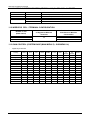
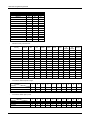
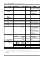
1.13 GAIN CONTROL (SYSTEM BASE (MAIN MENU 5) - SUB MENU 14)
-
Digital Keyset RX Gain
Country
DKTU
SLT
CO
DCO
DTMF
Tone
DVU
Int
Music
Ext
Music
WHTU
Australia
Belgium
Denmark
Finland
Germany
Italy
Netherlands
New Zealand
Norway
Spain
Sweden
UK
EU
CIS
Others
22
33
17
25
25
17
32
10
30
26
26
25
25
25
21
19
27
13
27
35
13
24
12
24
28
21
35
24
24
36
14
21
16
30
29
16
10
16
38
28
31
29
29
29
33
30
21
26
29
29
26
21
32
32
33
26
15
32
32
33
8
8
8
8
8
8
8
8
8
8
8
8
8
8
8
32
33
33
32
15
33
33
32
33
32
33
15
32
32
32
20
20
32
32
32
20
32
20
32
32
32
32
32
32
32
22
33
26
29
26
26
33
32
26
29
25
26
29
29
29
22
33
26
29
26
26
33
32
26
29
25
26
29
29
29
22
33
17
25
25
17
32
10
30
26
26
25
25
25
21
19
GDK-20W Programming Manual
-
SLT Rx Gain
-
Country
DKTU
SLT
CO
DCO
DTMF
Tone
DVU
Int
Music
Ext
Music
WHTU
Australia
Belgium
Denmark
Finland
Germany
Italy
Netherlands
New Zealand
Norway
Spain
Sweden
UK
EU
CIS
Others
36
27
27
26
36
27
39
28
15
26
28
36
32
32
10
32
21
32
16
38
32
32
32
32
32
32
32
32
32
30
32
26
32
32
32
32
32
32
36
32
32
32
32
32
21
32
26
32
23
23
32
26
29
32
24
28
23
32
32
24
4
4
4
4
4
4
4
4
4
4
4
4
4
4
4
46
36
30
32
27
30
38
50
45
32
39
27
32
53
32
32
32
32
32
32
32
32
32
32
32
32
32
32
32
32
36
29
37
29
29
37
32
50
18
32
31
29
32
32
20
36
29
37
29
29
37
32
50
18
32
31
29
32
32
20
36
27
27
26
36
27
39
28
15
26
28
36
32
32
10
DKTU
SLT
CO
DCO
DTMF
Tone
DVU
Int
Music
Ext
Music
WHTU
32
37
32
32
29
32
32
50
27
32
27
29
32
32
32
32
37
32
32
29
32
32
50
27
32
27
29
32
32
32
34
21
34
23
35
34
28
33
38
30
31
35
35
35
19
CO Line Rx Gain
Country
Australia
34
32
24
32
31
35
32
Belgium
21
29
26
26
38
36
32
Denmark
34
32
16
20
32
39
32
Finland
23
32
28
32
32
32
32
Germany
35
31
32
32
19
29
32
Italy
34
32
26
30
38
39
32
Netherlands
28
32
24
26
31
43
32
New Zealand
33
32
24
31
27
33
32
Norway
38
32
24
32
38
37
32
Spain
30
28
28
24
36
32
32
Sweden
31
32
32
32
34
41
32
UK
35
32
32
32
23
10
32
EU
35
32
24
32
30
32
32
CIS
35
32
24
32
43
32
32
Others
19
36
24
24
28
32
32
* Note : In Italy, all tones provided during conversation should be decreased by 5db.
20
GDK-20W Programming Manual
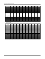
-
DCO Gain Table
-
Country
DKTU
SLT
CO
DCO
DTMF
Tone
DVU
Int
Music
Ext
Music
WHTU
Australia
Belgium
Denmark
Finland
Germany
Italy
Netherlands
New Zealand
Norway
Spain
Sweden
UK
EU
CIS
Others
31
21
32
35
35
32
21
32
36
26
30
30
32
32
26
32
29
32
32
32
32
29
27
32
37
37
32
32
32
37
26
26
20
32
32
28
26
26
26
30
32
32
26
26
24
32
32
32
32
32
32
32
32
32
32
32
29
32
32
32
28
38
32
25
25
32
26
28
32
32
32
25
25
25
32
32
36
37
37
37
37
36
32
37
32
40
37
32
32
32
32
32
32
32
32
32
32
32
32
32
32
32
32
32
32
32
37
38
29
29
38
37
50
27
32
26
29
32
32
32
32
37
38
29
29
38
37
50
27
32
26
29
32
32
32
31
21
32
35
35
32
21
32
36
26
30
30
32
32
26
DVU Rx Gain
Country
DKTU
SLT
CO
DCO
External
Music
WHTU
Australia
Belgium
Denmark
Finland
Germany
Italy
Netherlands
New Zealand
Norway
Spain
Sweden
UK
EU
CIS
Others
26
26
26
26
26
26
26
26
26
26
26
26
26
26
26
32
32
32
32
32
32
32
32
32
32
32
32
32
32
32
32
32
32
32
32
32
32
32
32
32
32
32
32
32
32
32
32
32
32
32
32
32
32
32
32
32
32
32
32
32
32
32
32
32
32
32
32
32
32
32
32
32
32
32
32
32
32
32
32
32
32
32
32
32
32
32
32
32
26
32
21
GDK-20W Programming Manual
-
-
-
DTMF RECEIVER Rx Gain
Country
SLT
CO
DCO
Australia
Belgium
Denmark
Finland
Germany
Italy
Netherlands
New Zealand
Norway
Spain
Sweden
UK
EU
CIS
Others
32
24
35
26
32
35
21
34
32
20
36
32
20
20
37
16
24
24
24
32
24
11
16
32
24
34
32
24
24
24
32
24
34
32
32
34
24
32
32
24
18
32
24
24
24
Wireless Handy Terminal Unit
Country
DKTU
SLT
CO
DCO
DTMF
Tone
DVU
Int
Music
Ext
Music
WHTU
Australia
Belgium
Denmark
Finland
Germany
Italy
Netherlands
New Zealand
Norway
Spain
Sweden
UK
EU
CIS
Others
22
33
17
25
25
17
32
10
30
26
26
25
25
25
21
19
27
13
27
35
13
24
12
24
28
21
35
24
24
36
14
21
16
30
29
16
10
16
38
28
31
29
29
29
33
30
21
26
29
29
26
21
32
32
33
26
15
32
32
33
8
8
8
8
8
8
8
8
8
8
8
8
8
8
8
32
33
33
32
15
33
33
32
33
32
33
15
32
32
32
20
20
32
32
32
20
32
20
32
32
32
32
32
32
32
22
33
26
29
26
26
33
32
26
29
25
26
29
29
29
22
33
26
29
26
26
33
32
26
29
25
26
29
29
29
22
33
17
25
25
17
32
10
30
26
26
25
25
25
21
Conversion detected pulse to digit
# of Pulse
Country
New Zealand
Sweden
Others
-
1
2
3
4
5
6
7
8
9
10
9
0
1
8
1
2
7
2
3
6
3
4
5
4
5
4
5
6
3
6
7
2
7
8
1
8
9
0
9
0
1
2
3
4
5
6
7
8
9
0
9
2
1
8
3
2
7
4
3
6
5
4
5
6
5
4
7
6
3
8
7
2
9
8
1
10
9
10
1
10
Conversion dialed digit to pulse
Digit
Country
New Zealand
Sweden
Others
22
GDK-20W Programming Manual
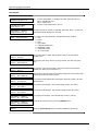
2. SYSTEM FEATURES
1. Admin Password
Description
Admin Password can be assigned to enter Admin Programming mode for only Administrator who knows the Admin
Password.
Operation
In Keyset Admin(In Station 100)
If admin password is programmed,
1.
Press the [TRNS/PGM] button and dial Code * #.
2.
Dial 4 Digits(Admin Password).
3.
When admin password is matched, the confirmation tone is heard.
Or Otherwise, the ERROR tone is heard.
If admin password isn’t programmed,
1.
Press the [TRNS/PGM] button and dial Code * #.( The system doesn’t request admin password input)
Pc Admin (In GDK Admin)
(Remote/Local Admin Programming and Other GDK-Admin Service)
If admin password is programmed,
1.
Select the specific admin service.
2.
The user will see the GDK Admin Password window.
3.
Then, dial the Admin Password(4 Digits)
4.
Press the OK button.
5.
If the admin password is matched, the user can access the specific admin service. If not, the user can’t access the
next step.
If admin password isn’t programmed,
1. Just, press the OK button without entering the admin password in step 3.
2. The user can access the specific admin service.
Remote Flash Upload (In GDK Admin)
If admin password is programmed,
1. Select “Flash upload” menu and fill out the “User Information” window.
2. Press the NEXT button and fill out the “Remote SW Upgrade” window.
3. Press the START button.
4. The user will see the GDK Admin Password window.
5. Then, dial the Admin Password(4 Digits).
6. Press the OK button.
7. If the admin password is matched, the program will start the flash upload. If not, the Remote Flash Upload program will
not start and the ISDN line will be disconnected immediately.
If admin password isn’t programmed,
1. Press the OK button without entering the admin password in 4 step.
2. The program will start the flash upload.
23
GDK-20W Programming Manual
Conditions
1. For Local Flash Upload, the system doesn’t compare admin password. So, the user can perform flash upload without
entering the admin password regardless of the programmed admin password.
2. Admin password is supported from PC Admin version A.0Cd (2000 Sep 18).
Admin Programming
1.
Admin Password
(System Base Program(Main Menu 5)-Sub-Menu 19)
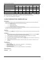
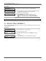
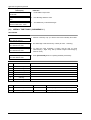
2. ALARM SIGNAL REPEATING
Description
The system can be programmed to recognize the status of an external contact (normally open or closed) from a relay.
When activated, the system will signal programmed stations with a single tone repeated at 1 minute intervals, or a
continuous tone. This capability is commonly employed to provide remote alarm signals. When used as an Alarm, the
assigned stations receive the programmed signal. To stop the signal, the Alarm must be deactivated (reset) from a
station assigned to receive the alarm signal.
Operation
At detection of the Alarm contact, the system responds by sending the appropriate alarm signal to assigned stations.
To terminate the alarm signal while idle;
Dial 65, confirmation tone is heard and the alarm signal is terminated at all assigned stations. If the Alarm
condition is cleared, the system will rearm the alarm.
To rearm alarm;
Clear the alarm condition and reset (terminate) the alarm signal. The preceding steps can be done in any order
to rearm.
Conditions
1.
The alarm contacts must be "dry" ( no voltage/current source connected ).
2.
A Single Line Telephone and Wireless Terminal doesn’t receive signal for the Alarm.
3.
The alarm signal will terminate when reset by any keyset assigned to receive the alarm signal, and will rearm
when both the alarm condition is cleared an reset by a keyset. The two actions may occur in any order.
4.
A flex button can be programmed for Alarm Reset.
Programming
Alarm/ ICM Box Signal
(Station Base Program(main menu2) - Station Attributes(Sub Menu1) - Terminal menu8)
Alarm Enable
(System Base Program(main menu5) - Alarm Attributes(Sub Menu10) - Terminal menu1 )
Alarm Contact Type
(System Base Program(main menu5) - Alarm Attributes(Sub Menu10) - Terminal menu2 )
Alarm Signal Mode
(System Base Program(main menu5) - Alarm Attributes(Sub Menu10) - Terminal menu3 )
Hardware
An external contact must be connected to the Alarm input on the MBU. This contact must be "dry", no voltage/current
source connected.
24
GDK-20W Programming Manual
3. AUDIO BEARER CAPABILITY 3.1KHz
Description
This feature enables SLT user to make a call with 3.1KHz Audio Bearer Capability instead of Speech Bearer
Capability when Bearer Capability 3.1KHz is enabled.
Operation
When a SLT makes an internal call to S-port,
When the system sends SETUP message to S port, 3.1KHz Audio Bearer Capability is used instead of
Speech Bearer Capability.
When a SLT makes an outgoing call with T-port (ISDN BRI line),
When the system sends SETUP message to T-port, 3.1KHz Audio Bearer Capability is used instead of
Speech Bearer Capability.
Admin Programming
Audio Bearer Capability 3.1KHz
(Station Base Program (Main Menu 2) – Station Attribute (Sub Menu 1) – Terminal Menu 3)
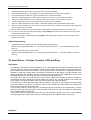
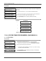
4. Auto-Delete of DVIB Messages
Description
The DVIB messages in the all stations may be deleted automatically after assigned term with admin programming. The
retrieved and saved messages by pressing [HOLD/SAVE] key will be deleted after assigned term. Non-saved messages
by pressing [HOLD/SAVE] will not be deleted automatically. But attendant can also delete non-retrieved messages.
(Attendant DVIB Management, Delete operation of a certain station’s all messages) This function works at 12:05:05 AM
in a day.
Operation
The retrieved and saved messages in all stations will be automatically deleted after assigned days as programmed.
While Auto-delete status (at DKTU),
While the messages are deleted automatically, the LCD is displayed as follows. (The count of day is decreased for
messages and when it comes to zero the messages of all stations will be deleted)
After the messages are deleted, the number of deleted message is displayed on the LCD.
Conditions
1.
2.
3.
4.
5.
6.
The messages in all stations will be deleted. But non-retrieved or non-saved message will not be
deleted.
The messages will be checked at 12:05:05 AM (night) and be deleted in a day.
When all DVIB ports are busy, auto-delete is not operated and waits until a DVIB port becomes
available.
The available range is 000~300 days. (When it is set to 000, this feature will not be operated. The
station user should delete the messages by [CONF] key.)
This feature will not be operated in SLT. (Since, the retrieved message is deleted automatically after onhook in SLT.)
After auto-delete feature is operated, the result will be displayed on the LCD of the station (XXX
MESSAGES DELETED) and off-hook to recover the LCD state.
25
GDK-20W Programming Manual
7.
When the number of days for Auto-Delete is changed, all the saved and retrieved messages will be
counted again with this new value.
8. If the user make off-hook while auto-delete status, the auto-delete operation is stopped and user may
make other operation in the keyset. The non-deleted messages will be deleted in the next day.
9. If the station is in use (including ringing state) in the auto-delete time, it will be retried after the station
becomes idle.
10. This feature will be operated regardless of DVIB Access mode.
Admin Programming
Auto Delete of Retrieved and Saved Messages
(System Base Program (Main Menu 5) – DVU Setting (Sub Menu 20) – Terminal Menu 3)
Hardware
DVIB
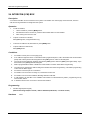
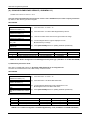
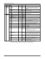
5. Automatic Fax Transfer
Description
The system can determine if an incoming call from the preprogrammed LCO line is for FAX (facsimile) or
for speech terminal by detecting the tone of the call (1100Hz, 0.5s ON/3s OFF repeated). When the
system detects a FAX tone from the incoming line within predetermined time, the system transfers the
call to the station that is a Fax machine. If the FAX tone is not detected within predetermined time,
system gives rings to stations that are programmed to ring.
Operation
Conditions
1. Only one LCO line can be programmed as a FAX CO line. If the FAX CO line is not programmed,
Automatic Fax Transfer will not be activated.
2. Station 104(first SLT port) is used as the FAX Station of GDK-20W. So, FAX machine should be
connected to the port for station 104 to use this feature.
3. If the FAX tone is not detected within the FAX tone detection time, the system will give rings to the
stations that are programmed to ring.
4. If the FAX CO line is not answered within the FAX CO call time, the line will be released.
5. Outside caller connected to the FAX CO line can hear the ring back tone while system is detecting a
FAX tone.
6. In order to transfer calls only from FAX to the FAX station of GDK-20W, do not assign CO ring to the
FAX station 104.
7. If a CO line is programmed for DISA and for Automatic FAX Transfer as well, incoming calls from that
CO line are served as DISA calls. So, if a user wants to call the FAX station, just call station 104 by
exploiting DISA call. So, If a user wants to call the FAX station, just call station 102 by exploiting DISA
call.
8. When the FAX machine goes to idle after a FAX call, the associated CO line is released.
9. If the FAX CO line is disconnected (“disconnect clear”) during a FAX call, CO line is released and FAX
machine becomes idle.
26
GDK-20W Programming Manual
Programming
1. Auto FAX Transfer CO
(System Base Program (Main Menu 5) – Sub Menu 15)
2. FAX Tone Detect Timer
(System Timers (Main Menu 6) - System Timer 1 (Sub Menu 1) - Terminal Menu 22)
3. FAX CO Call Timer
(System Timers (Main Menu 6) - System Timer 1 (Sub Menu 1) - Terminal Menu 23)
Hardware
1. MFB is needed.
6. AUTOMATIC PRIVACY
Description
As a default, the system provides privacy on all communications. If desired, the customer may disable the Privacy
feature, which will allow Attendant station to join the existing CO Line conversations without invitation.
Operation
If Privacy is enabled, from Attendant, or other stations;
Press a busy (LED lit steady) CO Line button, the station receives busy tone.
If Privacy is disabled, from Attendant;
Press a busy (LED lit steady) CO Line button, the Attendant station is connected to the conversation.
Conditions
1.
With Automatic Privacy disabled, privacy is still assured of all intercom, conference, CO to CO, ISDN CO, OffNet Forward calls.
2.
Attendant station must have a direct CO line appearance for this feature to operate.
Programming
Privacy
(System Base Program(main menu5) - System Attributes(Sub Menu1) - Terminal menu2 )
Hardware
None.
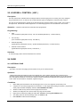
7. BACKGROUND MUSIC ( BGM )
Description
A Keyset can receive audio, generally music, from an internal or external source while idle. Music from the source is
received over the keyset speaker and will be shut-off during ring, pages or when the station is off-hook.
27
GDK-20W Programming Manual
Operation
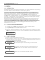
To activate or deactivate Background Music to a Keyset;
1.
Press the [TRNAS/PGM] button.
2.
Dial 73, background music is activated and music from first source is received.
3.
Press the [TRNAS/PGM] button.
4.
Dial 73, music from 2nd source is received, if selected.
Otherwise background music is deactivated.
To deactivate when 2nd source is selected,
1.
Press the [TRNAS/PGM] button.
2.
Dial 73. Background music is deactivated.
Conditions
1.
This code can be assigned to a Flex button.
2.
When the station lifts handset or presses the [MON] button, or dials a digit, the music is discontinued.
3.
The speaker volume is adjustable at the station by using the [UP/DOWN] key in the Digital Keyset.
4.
The connection for BGM are made with jack connector on the MBU.
5.
Music is continued one second after going to idle status.
6.
This feature is available in Keyset.
Programming
System Base Program(main menu5) - BGM Type(Sub Menu12)
Hardware
When an external music source is assigned, the source must be connected to the input terminal on the PMU.
8. BATTERY BACK-UP, MEMORY
Description
The system database memory is protected from power loss by a long life (minimum 5 years) lithium dry cell battery.
Should local power fail, the battery will maintain the system memory and proper operation of the system clock.
Operation Operation of this feature is automatic when installed.
Programming
Hardware
The plus battery terminal must be properly connected to the MBU and Switch position 1 on the MBU must be in the
on position to properly protect the system memory from a power outage.
28
GDK-20W Programming Manual
9. BUSY LAMP FIELD ( BLF )
Description
When the user assigns a Flexible button on the Keyset as a Direct Station Selection button (DSS), the LED
associated with the button also provides an indication of the status of the assigned station. Such status indicators are
known as a Busy Lamp Field that is; a group of lamps which indicate the busy status of stations.
Operation Operation of this feature is automatic when programmed by the user.
Condition
Programming
Hardware
None.
10. CONFERENCE
10.1 CONFERENCE - ADD-ON
Description
A station user can establish a call with one station and one CO Line.
Operation
To establish a conference;
With the first call established, press the [CONF] button, the existing call is on hold and intercom dial-tone is
received.
2.
Place call to internal party.
3.
When answered, press the [CONF] button.
4.
When all parties have been called, press the [CONF] button again, all parties can converse.
1.
Conditions
1.
The [CONF] button will remain lit on the initiating station throughout the duration of the conference.
2.
There is no limit on the number of 3-way conference.
3.
If a conferee hangs up in a 3-way conference, the conference is dropped and the other two parties are
connected as normal 2-way conversation.
4.
If a conference master hangs up after pressing [CONF] during conference, the [CONF] LED will flash at 120
ipm. If a master presses the flashing [CONF] button in idle status, the conference is dropped. To reenter the
conference, lifts handset or presses the [MON] button and presses the flashing [CONF] button.
5.
If the master receives error or busy tone from an internal party while setting up the conference, he can receive
ICM dial tone again by pressing the [CONF] button.
6.
The conference master, while setting up an internal conference, can not Camp-on to a station, when he has
dialed and received ICM busy tone.
7.
If a conference master hangs up during conference setup, the [CONF] LED continue to flash, and the master
can retrieve the waiting member by off-hook and pressing [CONF] button.
8.
To establish a conference, the originator must have a [CONF] button.
9.
A Wireless Terminal can not be a conference master.
Programming
Hardware
None.
29
GDK-20W Programming Manual
10.2 CONFERENCE - MULTI-LINE
Description
The system will allow maximum 2 Co Lines with one internal telephone. The internal station can exit the conference
and leave the conference unsupervised.
Operation
To set up a multi line conference;
1)
2)
3)
Station (A) which engaged in talking to a CO Line or internal station presses the [CONF] button. The [CONF]
button will light and Party (B) hears MOH. ICM dial tone is received by Station (A).
Station (A) dials the another external party to be included in the conference (Party (C)).
When Party (C) answers, Station (A) presses the [CONF] button twice and all parties are connected.
Conditions
1.
The [CONF] button will remain lit on the initiating station throughout the duration of the conference unless
unsupervised conference is established. In this case, the [CONF] button will flash at 120 ipm.
2.
A multi-line conference is limited to 2 CO lines. If the user attempts to increase the conference beyond that
limit he will receive error tone.
3.
Station (A) may exit the conference by pressing the [CONF] button. (Unsupervised conference mode). If a
master presses the flashing [CONF] button in idle status, the conference is dropped. To reenter the
conference, lifts handset or presses the [MON] button and presses the flashing [CONF] button.
4.
Station (A) can disconnect the conference by going idle status.
5.
To establish a conference the originator must have a [CONF] button.
6.
If a conference master hangs up during conference setup, the [CONF] LED continue to flash, and the master
can retrieve the waiting member by off-hook and pressing [CONF] button.
7.
A Wireless Terminal can not be a conference master.
Programming
Unsupervised Conference Timer
(System Timers(main menu6) - System Timer 1 ( Sub Menu 1 ) - Terminal Menu14)
Multi-Line Conference
(System Base Program(main menu5) - System Attributes(Sub Menu1) - Terminal menu4 )
Related Features
Hardware
None.
10.3 CONFERENCE - UNSUPERVISED
Description
The system will allow maximum 2 CO lines in an unsupervised conference. The internal station will exit a conference
and leave the conference unsupervised.
Operation
30
GDK-20W Programming Manual
Station (A) leaves the multi-line conference unsupervised by pressing the [CONF] button and going idle status. The
[CONF] LED flashes at 120 ipm rate. If Station (A) goes idle status without pressing the [CONF] button, the
conferees are dropped and the conference is canceled.
To reenter the conference;
1)
Station (A) lifts the handset and presses the [CONF] button. The all parties receive a warning tone.
Conditions
1.
To set up a conference the telephone must have a [CONF] button.
2.
The unsupervised conference timer will be reset if the internal party reenters the conference.
3.
An unsupervised conference is governed by the conference timer.
Programming
Multi-Line Conference
(System Base Program(main menu5) - System Attributes(Sub Menu1) - Terminal menu4 )
Unsupervised Conference Timer
(System Timers(main menu6) - System Timer 1 ( Sub Menu 1 ) - Terminal Menu14)
Related Features
None.
Hardware
11. Day/Night Mode Change -Automatic
Description
The system can be placed in Day/ Night mode operation automatically, if weekly time table is programmed and auto
Day/Night mode is chosen by the attendant station. Attendant stations can change the specific ring service mode by
pressing [DND] button. According to pressing [DND] button, the ring mode will be changed day/night/auto sequentially. In
this mode, ring mode follows the weekly time table that can be set in admin( System base program(Main menu5) Weekly time table(Sub menu 21) - Day / Night time program( Terminal menu 1-7 ) )
The default value of weekly time table is
Day
Day Start Time
Night Start Time
Mon
09:00
18:00
Tue
09:00
18:00
Wen
09:00
18:00
Thu
09:00
18:00
Fri
09:00
18:00
Sat
--:--
00:00
Sun
--:--
00:00
Each table’s default setting is the same as above value.
Operation
To change Day/Night/Auto Ring Mode
1. To enter night mode, press the [DND/FOR] button once at attendant in day mode. The [DND/FOR] LED lights steady-
31
GDK-20W Programming Manual
on.
2. To enter auto ring mode, press the [DND/FOR] button once at attendant in night mode. The [DND/FOR]
LED flash 480 IPM in auto ring mode.
To change day mode, press the [DND/FOR] button once at attendant in auto mode. The [DND/FOR] LED lights off.
Conditions
1.
Only attendant can access the ring mode changing.
2.
In auto ring mode, day/night ring is serviced according to the weekly time table.
3.
Only ring assigned stations can receive the incoming ring in a any ring mode.
4.
If both day and night start time are not programmed in weekly time table, auto ring mode can’t be entered.
5.
The day start time can’t be same to the night start time.
6.
By default, the night ring is serviced all day on Saturday and Sunday in Auto ring mode.
Admin Programming
1. Station Class of Service
(Station Base Program(main menu2) - Sub Menu3)
2. CO Line Ring Assignment
(CO Line Base Program(main menu3) - Sub Menu7)
3. External Night Ring
(System Base Program(main menu5) - System Attribute(Sub Menu1) - Terminal menu3)
4. Attendant Assignment
(System Base Program(main menu5) - Sub Menu2)
5. Weekly time table program for Auto Day/Night
(System Base Program(main menu5) – Weekly time table(Sub Menu21) – Day/Night time(Terminal
1-7) )
12. DATA LINE SECURITY & BEARER CAPABILITY 3.1 KHz
Description
This feature provides a busy station protection from override and camp-on, which could cause errors in data being
transmitted. The same Admin programming field, Data Line Security previously controlled data line security and
3.1KHz audio bearer capability. In BASIC III version: 2.x or B.x, new Admin field for 3.1KHz audio bearer capability is
added for the users to be able to program each feature as desired.
Operation
A station assigned Data Line Security can not be intruded by an attendant or camped-on during conversation.
Stations or an attendant attempting to camp-on or intrude will receive error tone.
Conditions
1. Rings on station with Data Line Security can not be picked up.
2. Rings on station with Data Line Security via DID(MSN)/DISA are not re-routed to attendant station.
3. During SLT port with Data Line Security is connected to CO line, the outside party releases first, (DISCONNECT
message or Loop Disconnect detection signal), SLT port will hear silence. This feature is able an answering
device to release as soon as CO party hang-up.
Programming
Data Line Security
(Station Base Program(main menu2) - Station Attributes(Sub Menu1) - Terminal menu10 )
32
GDK-20W Programming Manual
Bearer Capability 3.1KHz
(Station Base Program (Main Menu 2) – Station Attributes (Sub Menu 1) – Terminal Menu
14)
* Note : In Norwegian version, Terminal Menu is 14 for Bearer Capability 3.1 KHz
Related Features
Hardware
None
13. Dial By Name – Speed Dial and ICM Call
Description
The system will allow station users to dial extension numbers by entering a name that has been programmed for the
station (intercom). Also each station may be assigned with a name up to 7 characters and speed dial (system and
station) number may be assigned with a name of up to 16 characters. When the names are programmed in the digital
display keyset, the user may select a station or speed dial number by the name. The user selects from one of three
directories (intercom, user speed dial or system speed dial) and enters alpha-numeric data with 2 dial pad keystrokes per
character. The system finds and displays the first matched name based on the characters entered. The user may at any
point scroll using [S]/[T] buttons through the names in the directory and select a name to call. If user wants to display
the matched phone number to the selected name, press [FLASH] button.
Operation
To store a Speed Dial number with name,
1.
Press [TRNAS/PGM] button in a keyset. (at the attendant station for System Speed Dial)
2.
Press [SPEED] button.
3.
Dial the station/system speed bin.
4.
If desired, press the CO line or group button.
5.
Dial the desired phone number (up to 24 digits).
6.
Press [HOLD/SAVE] button.
7.
Enter the name by dialing 2-digit for each character. (up to 16 characters, Refer to the English Character Set.)
8.
Press [HOLD/SAVE] button.
To access Dial By Name (User Speed bin/System Speed bin),
1.
Press the [SPEED] button.
2.
Press the [SPEED] button again.
3.
Dial I(1)/U(2)/S(3) (I (Intercom), U (User Speed bin), S (System Speed bin)) and stored names in memory are
displayed in alphabetical order.
To search names in LCD by entering character;
1.
2.
3.
4.
LCD displays two names.
(User Speed bin or System speed bin)
Enter alpha-numeric data with 2 dial pad keystrokes per character, then LCD displays names which are started with
the user input in alphabetical order. (cursor points to the first line in LCD.) (Ex. When you dial ‘45’)
Entering another alpha-numeric data, then LCD displays names started with the updated user input (first two
characters) in alphabetical order. (cursor points to the first line in LCD). It is continued until user stops entering the
alpha-numeric data. (Ex. When you dial ‘97’)
The matched name is displayed.
To search names in LCD by scrolling;
33
GDK-20W Programming Manual
1.
2.
3.
4.
LCD displays names.
Press [DOWN] key with cursor on the first line, then cursor points to the second line in LCD.
Press [UP] key with cursor on the second line, then cursor points to the first line in LCD.
Press [DOWN] key with cursor on the second line, next two lists outside LCD are displayed.
To show the dial number related to the name for the speed bin;
1.
2.
3.
Cursor points a name displayed in LCD.
Press [FLASH] button, and the dial number related to the name is displayed.
Press [FLASH] button once more, the name related to the dial number is displayed. (toggle)
To dial each station or speed dial number;
1.
2.
Cursor points a name.
(But, you may dial number(digit 2) to select second speed number.)
Press [HOLD/SAVE] button, then the stored number is dialed.
Conditions
1.
Available characters as a name are A--Z, space, period, colon and comma.
2.
LCD displays 2 names for DKTU.
3.
If user dials a group (I/S/U) which has no entry, error tone is heard.
4.
You should enter System Speed dial in only Attendant station. (If you try to enter System Speed Dial in the other
station, error tone will be heard.)
5.
If a station without LCD tries to activate this feature, error tone is heard.
6.
In SLT and no LCD DKTU, only station name can be entered.
7.
When there is no matched name for the user input while searching a name, error tone is heard.
8.
The Speed Dial which has only phone number without name will not be listed by the Dial by Name.
9.
Pressing [CALLBK] button, the last letter of user input is deleted and previous matched name is displayed. If you
press just 1 digit to enter a character, only the digit will be deleted. (There is no change in the LCD.) And, if pressing
[CALLBK] button without entering any letter, system takes no action.
10. If the user input letters are all erased with [CALLBK] button, the LCD will display the first name in alphabetical order.
(The cursor will also indicate the first name.)
11. Scrolling and entering characters may be used simultaneously to search a name.
12. When Dial By Name cooperates with LNR, LCD displays the dial number, not the name.
13. Pressing [▼] key while entering a phone number, the last digit will be erased. If you press just 1 digit to enter a
character, only the digit will be deleted. (There is no change in the LCD.)
14. Pressing [▼] key while entering station name, the last character will be erased
15. While entering a name, you may press ‘4, 5, 6’ or ‘7, 8, 9’ as a second digit instead of ‘1, 2, 3’. Ex) To enter ‘J’, you
may press ‘5 1’, ‘5 4’ or ‘5 7’.
16. Entering a character to search a name and then pressing [▼] key, the cursor will indicate the first letter.
17. Dial by Name data (System/Station) will be printed with Database Print feature (Main Menu 12).
18. Trying to access Speed Dial in a station which is not allowed to access it (Main Menu 2– Sub Menu 1 –
Terminal Menu 2), error tone will be heard.
19. Pressing [▲]/[▼] key after entering a speed bin number, the previous stored phone numbers are displayed with the
speed bin number. (It will be searched station speed base or system speed base.)
20. For entering alpha-numeric data, see the English Character Set.
Admin Programming
Speed Dial Access
(Station Base Program(Main Menu 2) – Station Attributes Program(Sub Menu 1) – Terminal Menu 2)
Relate Features
34
GDK-20W Programming Manual
1.
Station Speed Dial
2.
System Speed Dial
. – 13
A - 21
D - 31
Q – 11
B - 22
E - 32
Z – 12
C - 23
F - 33
1 - 10
2 - 20
3 - 30
G - 41
J - 51
M - 61
H - 42
K - 52
N - 62
I - 43
L - 53
O - 63
4 - 40
5 - 50
6 - 60
P - 71
R - 72
S - 73
Q - 7*
7 - 70
T - 81
U - 82
V - 83
8 - 80
W - 91
X - 92
Y - 93
Z - 9#
9 - 90
*1 - Blank
*2 - :
0-00
#
*3 - ,
< English Character Set >
14. DIFFERENTIAL RING (DIGITAL KEYSET ONLY)
Description
The user of a proprietary digital keyset can program the frequency of the ring signal sent to the speaker of the keyset.
Four frequency settings are available to allow users to distinguish which telephone in a given area is ringing. The
setting will affect all ringing signals sent to the speaker of the keyset while idle, including intercom signals. The ring
cadence is not changed by this setting.
Operation
To set the ring type from digital keyset only
TRANS/PGM
+ 50 +
Ring_Type (1-4) +
HOLD/SAVE
Conditions
1.
Each time the user dials a digit 1 to 4, the speaker will receive the appropriate ring signal. Pressing
[HOLD/SAVE] button stores the last selected ring frequency.
2.
This setting affects ICM ring and CO ring.
Programming
Related Features
Hardware
None.
35
GDK-20W Programming Manual
15. Delayed DISA
Description
When the CO line is DISA type, the system can respond immediately or after the DISA Delay timer expire for incoming
CO call according to DISA Delay timer setting. So, if the timer is not 0, the incoming DISA CO call is first routed to ring
assigned stations or group and the caller can hear the DISA system announcement in case the programmed timer
expires. If not, the incoming DISA CO call is route to DVU and the caller will hear the DISA system announcement
without delay.
This is an enhancement of the existing feature “DISA”.
Operation
To enable this feature
1.
The CO line should be set as DISA type
2.
The DISA Delay timer should be programmed as the specific time.
To disable this feature(DISA without delay);
1.
The CO line should be set as DISA type
2.
The DISA Delay timer is set to 0 second.
If this feature is enabled;
1.
When the CO line is DISA type and the CO call comes, all ring assigned station will be received the CO ring.
2.
The caller will hear DISA system announcement after DISA Delay Timer. And the stations will stop ringing.
If this feature isn’t enabled(Normal DISA);
1.
The CO line is DISA type and the DISA CO call comes.
2.
The caller will hear DISA system announcement without the specific delay.
Conditions
1.
If the DISA Delay timer set 0, the system will behavior as the normal DISA.
2.
When there is no available DVIB port, ring assigned stations will be continuously received the CO ring after DISA
Delay Timer expires. When there is an available DVIB port, ring assigned stations will stop ringing and the caller will
hear the DISA system announcement
3.
Before DISA Delay Timer expires, the incoming call is routed to ring assigned station or group. So Hunt group has
the precedence for ring assignment
4.
If DISA Delay timer expires during group announcement, group announcement will be end and system
announcement will be presented.
5.
Admin Programming
1.
DISA Type
(CO Line Base Program (Main Menu 3) – DISA Type(Sub Menu 4) )
2.
DISA Delay Timer
(System Timer (Main Menu 6) – System Timer 2 (Sub Menu 2) – Terminal Menu 7 )
36
GDK-20W Programming Manual
16. Direct Call Pick Up
Description
An ICM and CO calls can be picked up by another station.
Operation
To assign Direct Pick-up button to flexible button
[TRNAS/PGM] + {FLEX} + 7 + [HOLD]
To pick up the call of other station(From DKTU)
1.
A user hears a tone ringing ICM/CO ringing of other station.
2.
Lift handset or press [MON] button.
3.
Dial Code 7 and the station number or press {Pick-up} button and the station number to be answered.
4.
The user picks up the call.
To pick up the call of other station(From SLT)
1.
A user hears a tone ringing ICM/CO ringing of other station.
2.
Lift handset .
3.
Dial Code 7 and the station number and the station number to be answered.
4.
The user picks up the call.
5.
Conditions
1.
When picking up a transferred CO line or incoming CO line, the line is automatically connected.
2.
The user must have the {CO} button or {LOOP} button to pick up a CO line.
3.
About the multiple call on a station, the pick up will be performed according to PLA( transferred line, recall,
4.
If more than one call which have the same priority is ringing at the telephone, the oldest call is pick up
incoming CO, ICM Ring in order)
5.
Queue callback cannot be picked up via directed call pick-up, a station attempting this will receive error tone.
6.
The call from ICM Box can be picked up.
7.
About the call back ring, the direct pick-up doesn’t work. In this case, error tone & no pick-up call LCD message will
be displayed.
8.
When ICM Answer Mode of the station is “HF” or “PV” mode, the call to the station cannot be picked up.
37
GDK-20W Programming Manual
17. Door Open
Description
At most 2 relays can be used for Door Open.
Operation
To open the door by using relay 1;
Dial #*1.
To open the door by using relay 2;
Dial #*2.
Conditions
Programming
1. External Control Contact
(System Base Program (Main Menu 5) - Sub Menu 11)
2. Door Open Timer
(System Timers (Main Menu 6) - System Timer 1 (Sub Menu 1) - Terminal Menu 17)
Hardware
1. MFB is needed.
2.
3.
18. DVIB
18.1 DVIB – System Greetings and Prompts
Description
Attendant station in the system can record the voice announcements like system greetings and prompts.
System greetings and DVIB MOH should be recorded before use. System prompts in user’s language are
contained as default in DVIB. But users can also modify those messages.
Prompts for date and time are contained in DVIB to be used for date and time stamping. With the help of
these prompts, users can understand when the voice message has arrived. Prompts for date and time
are also built-in and recorded in user’s language.
Operation
To record system announcements from Attendant;
1) Press [TRNAS/PGM] and dial Code # 4.
2) Dial announcement type.
3) Dial announcement number. If there is already a recorded announcement in the number dialed,
the recorded announcement will be played. (If user doesn’t dial any digit in 3 seconds after the
end of recorded announcement play, user can select announcement type again for GDK-20W
goes to the above step 2) automatically.)
4) Dial source number for recording. Dial 1 when the external MOH will be used as a source for
recording, or dial 2 when DKTU will be used. If you selected external MOH, you will hear the
sound of external MOH so that it is possible to start recording the announcement at the time that
you want.
38
GDK-20W Programming Manual
5) Dial # to start recording. Start the announcement after you hear confirmation tone.
6) At the end of the announcement, dial [HOLD/SAVE] to finish recording.
To delete system announcements from Attendant;
1) Press [TRNAS/PGM] and dial Code # 4.
2) Dial announcement type.
3) Dial announcement number. Only when there is a recorded announcement in the number dialed,
the recorded announcement is played.
4) Dial * during the play to delete the announcement.
System Greetings and DVIB MOH : Announcement type 1
Number
Announcement Name
1
2
Day Time System Greeting
Night Time System Greeting
Circular and Terminal Hunt Group
Greeting
3
Description
When DISA call comes during day mode.
When DISA call comes during night mode.
When Ring Timer for the group expires.
4
UCD Group First Announcement
5
UCD Group Second
Announcement
When a call is in the waiting queue for UCD First
Announcement time.
When a call is in the waiting queue for UCD Second
Announcement time after UCD Group First Announcement.
6
7
Ring Group Announcement
When Ring Timer for the group expires
DVIB MOH
8
SLT MW Indication Announcement
MOH in DVIB.
If SLT has message wait, this announcement is heard when
off hook.
9
10
Off-net
Announcement
Group
Announcement
Forward
Overflow
System Prompts : Announcement type 2
Number
Announcement Name
1
Time Out Prompt
2
3
4
5
6
7
8
9
Retry Prompt
Busy Prompt
DND Prompt
Invalid Prompt
No Answer Prompt
Transfer To Attendant Prompt
Authorization Code Prompt
Record Start Prompt
Description
When DISA caller does not dial any digit in IDP time.
(Not Used now)
To prompt DISA caller to dial again.
When called station is busy.
When called station is in DND.
When DID/DISA call is invalid.
When a call is not answered within No Answer Time.
When DID/DISA call is forwarded to attendant station.
To prompt DISA caller to dial Authorization Code.
To prompt the caller to leave voice message.
Conditions
1. System Greetings and Prompts can be recorded only at the attendant in the system.
2. There is no time limit when attendant records system greetings and prompts.
3. If the DVIB is not installed, it is not possible to record system announcements. Error tone will be heard
when recording is tried.
4. If there is a recorded announcement already, the recorded announcement will be played after user
dialed the announcement number.
5. When the attendant station records or deletes any of the System Greetings and Prompts, all the DVIB
ports should be idle. Otherwise, busy tone will be heard.
6. When the call is being transferred to attendant station, Transfer to Attendant Prompt is announced to
the caller, and Ring Back Tone will be heard after the announcement.
7. If there are no recorded greetings or announcements, the corresponding tones will be heard.
39
GDK-20W Programming Manual
8. External caller hears Ring Back Tone for a few seconds until the System Greeting announcement is
started.
9. At most 400 voice messages are available with the optional memory installed on DVIB. Among these,
there are only 20 messages that are used for system’s purpose. They are, for example, System
Greetings, Announcements for station group, DVIB MOH, and etc. Only 6 of them are being used now
and the remaining 14 are reserved for future.
10.When DVIB MOH is used as the source of system MOH, 1 port of DVIB should be always reserved for
MOH feature even when MOH is not used.
11.If DVIB is not installed in the system or there is no channel available in DVIB, error tone is heard when
MOH type 3, DVU, is selected in Admin programming.
12.
Programming
1. DVU Access
(Station Base Program (Main Menu 2) – Station Attributes (Sub Menu 1) - Terminal Menu 11)
2. DVU User Record Timer
(System Timer (Main Menu 6) – System Timer 1(Sub Menu 1) - Terminal Menu 24)
3. Valid User Message Timer
(System Timer (Main Menu 6) – System Timer 2 (Sub Menu 2) - Terminal Menu 2)
4. DID/DISA Forward To DVIB for Busy Case
5.
(System Base Program (Main Menu 5) – DID/DISA Destination (Sub Menu 17) – Terminal Menu 1)
6. DID/DISA Forward To DVIB for No Answer Case
7.
(System Base Program (Main Menu 5) – DID/DISA Destination (Sub Menu 17) – Terminal Menu 2)
8. DID/DISA Forward To DVIB for Attendant No Answer Case
9.
(System Base Program (Main Menu 5) – DID/DISA Destination (Sub Menu 17) – Terminal Menu 3)
Hardware
1. DVIB is needed.
2.
3.
18.2 DVIB – Voice Announcement with DID/DISA Line
Description
Recorded system greetings and prompts can be used for voice-guided DID/DISA.
Operation
DID (MSN) Line
Case
Busy/DND
No Answer
Admin Field
Value
Action and Announcements Provided
DID/DISA Forward To DVIB
for Busy Case (5-17-1)
No
Yes
DID/DISA Busy Destination
(5-6-1)
with
DID/DISA
Forward To DVIB for Busy
Case (5-17-1) NO
DID/DISA Forward To DVIB
for No Answer Case (5-17-2)
Tone
ATTD
Refer to “DID/DISA Busy Destination (5-6-1)” below.
Busy/DND Prompt + Record Start Prompt + Beep Tone
Recorded message is saved for the station in busy/DND.
Incoming call is released immediately.
Ring is distributed to all the stations that are assigned CO
ringing. If there is no station assigned ringing, the call goes to
attendant station after Busy/DND Prompt is announced.
Call goes to attendant station.
No Answer Prompt + Transfer To Attendant Prompt + RBT
No Answer Prompt + Record Start Prompt + Beep Tone
Recorded message is saved for this station.
No Answer Prompt + Record Start Prompt + Beep Tone
Recorded message is saved for attendant station.
No
Yes
No Answer at
Attendant
DID/DISA Forward To DVIB
for Attendant No Answer
Yes
40
GDK-20W Programming Manual
Case (5-17-3)
DID/DISA Error Destination
(5-6-2)
No
Tone
ATTD
Case
Admin Field
Value
Incoming Call
DISA Line Use
(3-4)
DID/DISA Error Destination
(5-6-2)
Yes
Invalid
Continuous ringing at attendant station.
Incoming call is released immediately.
Ring is distributed to all the stations that are assigned CO
ringing. If there is no station assigned ringing, the call goes to
attendant station after invalid prompt is announced.
DISA Line
Inter
Digit
Timeout
Busy/DND
DID/DISA Forward To DVIB
for Busy Case (5-17-1)
Tone
ATTD
No
Yes
Invalid
No Answer
-
-
DID/DISA Forward To DVIB
for No Answer Case (5-17-2)
No
Yes
After all busy
retries
DID/DISA Busy Destination
(5-6-1)
Tone
ATTD
After all error
retries
DID/DISA Error Destination
(5-6-2)
Tone
ATTD
No Answer at
Attendant
DID/DISA Forward To DVIB
for Attendant No Answer
Case (5-17-3)
CO Access
Code
DISA Account Code (3-1-5)
*1) DT means Dial Tone.
Yes
No
No
Yes
Action and Provided Announcements
GDK-20W answers this incoming call.
System Greeting (Day or Night)
Incoming call is released immediately.
Call goes to attendant station.
Transfer To Attendant Prompt + RBT
Caller can try again.
Busy/DND Prompt + Retry Prompt + System Greeting
Busy/DND Prompt + Record Start Prompt + Beep Tone
Recorded message is saved for this station in busy/DND.
Caller can retry again.
Invalid Prompt + Retry Prompt + System Greeting
Call goes to attendant station.
No Answer Prompt + Transfer To Attendant Prompt + RBT
No Answer Prompt + Record Start Prompt + Beep Tone
Recorded message is saved for this station.
DISA Line is released automatically.
Call goes to attendant station.
Busy Prompt + Transfer To Attendant Prompt + RBT
DISA Line is released automatically.
Call goes to attendant station.
Invalid Prompt + Transfer To Attendant Prompt + RBT
No Answer Prompt + Record Start Prompt + Beep Tone
Recorded message is saved for attendant station.
Continuous ringing at attendant station.
DISA Caller is connected to a new outside line.
Authorization Code Prompt + DT
*2) RBT means Ring Back Tone.
Conditions
1. This feature “DVIB – Voice Announcement with DID/DISA Line” is enabled by Admin field DVU Annc
(3-1-7) YES. If DVU Annc is set to NO, no announcement is provided (DID/DISA feature works as if
no DVIB with GDK-20W.).
2. Transfer to Attendant Prompt is provided when the call is being transferred to the attendant station.
3. When there is no recorded announcement, the corresponding tone is provided.
4. External caller hears Ring Back Tone for a few seconds until the System Greeting announcement is
started.
5. If DISA call comes in and all the ports of DVIB are used at that time, the call cannot be answered until
any of DVIB ports becomes idle and the caller hears Ring Back Tone.
6. ISDN terminal (S port) can not receive DVIB voice message.
7. Station with Data Line Security YES can not receive DVIB voice message even though DID/DISA
Forward To DVIB for Busy Case and No Answer Case are YES.
8. When the call is routed to Ring Group, any DVIB message can not be saved for that group.
Programming
1.
2.
3.
DISA Account
(CO Base Program (Main Menu 3) – CO Attributes (Sub Menu 1) - Terminal Menu 5)
DVU Announcement
41
GDK-20W Programming Manual
(CO Base Program (Main Menu 3) – CO Attributes (Sub Menu 1) - Terminal Menu 7)
5.
DID Line Use
6.
(CO Base Program (Main Menu 3) – ISDN CO Attributes (Sub Menu 2) - Terminal Menu 4)
7. DISA Type
8.
(CO Base Program (Main Menu 3) – Sub Menu 4)
9. DISA Retry Counter
10.
(System Base Program (Main Menu 5) – Sub Menu 7)
11.DID/DISA Busy Destination
12.
(System Base Program (Main Menu 5) – DID/DISA Destination (Sub Menu 6) – Terminal Menu 1)
13. DID/DISA Error Destination
14.
(System Base Program (Main Menu 5) – DID/DISA Destination (Sub Menu 6) – Terminal Menu
2)
15. DID/DISA Forward To DVIB for Busy Case
16. (System Base Program (Main Menu 5) – DID/DISA Destination (Sub Menu 17) – Terminal Menu
1)
17. DID/DISA Forward To DVIB for No Answer Case
18. (System Base Program (Main Menu 5) – DID/DISA Destination (Sub Menu 17) – Terminal Menu
2)
19. DID/DISA Forward To DVIB for Attendant No Answer Case
20. (System Base Program (Main Menu 5) – DID/DISA Destination (Sub Menu 17) – Terminal Menu
3)
21. DID/DISA No Answer Timer
22. (System Timer (Main Menu 6) – System Timer 1 (Sub Menu 1) – Terminal Menu 13)
23. DVU User Record Timer
24. (System Timer (Main Menu 6) – System Timer 1 (Sub Menu 1) – Terminal Menu 24)
25. Valid User Message Timer
26. (System Timer (Main Menu 6) – System Timer 2 (Sub Menu 2) – Terminal Menu 2)
4.
Hardware
1. DVIB is needed.
2.
18.3 DVIB – User Greeting & Voice Message Wait
Description
If the access to the DVIB port is allowed, a user can record User Greeting and then his/her calls will be
forwarded to DVIB port after DVIB Station Forward Answer time (programmable). And caller can leave
voice message wait at this station after user greeting. Recording time of each voice message is bounded
by the DVIB User Record Time, which is 20 seconds by default (programmable).
Operation
DKTU Users;
To record user greeting from a Station;
Off Hook
+ [DND/FOR] +
Code 7 +
Code # +
Voice +
User greeting is stored permanently, and Call Forward to the DVIB is activated.
To delete user greeting from a Station;
Off Hook
+ [DND/FOR] +
Code 7 +
Code * +
User greeting is deleted, and Call Forward to the DVIB is cleared.
To deactivate Call Forward to DVIB from a Station;
42
On Hook
On Hook
GDK-20W Programming Manual
On Hook
+ [DND/FOR]
Off Hook
+ [DND/FOR] +
Code # +
On Hook
Call Forward to DVIB is deactivated. But user greeting is not deleted. To delete user greeting, use the
procedure described above.
43
GDK-20W Programming Manual
To activate Call Forward to DVIB from a Station;
Off Hook
+ [DND/FOR] +
Code 7 +
On Hook
Recorded user greeting is used. If there is a recorded user greeting, it is heard.
To leave voice message wait;
Talk with normal voice sound after both User Greeting and Beep tone.
To hear voice message wait;
Press [CALLBK] button. Time & Date prompt for the recorded message is provided and then voice
message is played.
To hear current voice message wait again;
Press [CALLBK] button. Time & Date prompt for the current message is provided and then voice
message is played again.
To hear the next voice message after deleting the current voice message;
Press [CONF] button. The current voice message is deleted and the next message is played.
To hear the next voice message after saving the current voice message;
Press [HOLD/SAVE] button. The current voice message is saved and the next message is played.
SLT Users:
To record user greeting from an SLT;
Off Hook
+ 5 4 +
Code 7 +
Code # +
Voice +
On Hook
User greeting is stored permanently, and Call Forward to the DVIB is activated.
To delete user greeting from an SLT;
Off Hook
+ 5 4 +
Code 7 +
Code * +
On Hook
User greeting is deleted, and Call Forward to the DVIB is cleared.
To deactivate Call Forward to DVIB from an SLT;
Off Hook
+ 5 4 +
Code # +
On Hook
Call Forward to DVIB is deactivated. But user greeting is not deleted. To delete user greeting, use the
procedure described above.
To activate Call Forward to DVIB from an SLT;
Off Hook
+ 5 4 +
Code 7 +
On Hook
Recorded user greeting is used. If there is a recorded user greeting, it is heard.
To leave voice message wait;
Talk with normal voice sound after both User Greeting and Beep tone.
To hear voice message wait;
Dial 5 7. Time & Date prompt for the recorded message is provided and then voice message is
played.
To delete the voice message;
Go on hook after or while the voice message is played. If users hang up while Time & Date prompt
is heard, voice message is not deleted.
Wireless Terminal users:
To record user greeting from a Wireless terminal ;
[ON/OFF (
)]
+ 5 4 +
Code 7 +
Code # +
Voice +
[FUNCTION (
User greeting is stored permanently, and Call Forward to the DVIB is activated.
To delete user greeting from a Wireless terminal ;
[ON/OFF (
)]
+ 5 4 +
Code 7 +
Code * +
User greeting is deleted, and Call Forward to the DVIB is cleared.
44
[ON/OFF (
)]
)]
GDK-20W Programming Manual
To deactivate Call Forward to DVIB from a Wireless terminal ;
[ON/OFF (
)]
+ 5 4 +
Code #
Call Forward to DVIB is deactivated. But user greeting is not deleted. To delete user greeting, use the
procedure described above.
To activate Call Forward to DVIB from a Wireless terminal;
[ON/OFF (
)]
+ 5 4 +
Code 7
Recorded user greeting is used. If there is a recorded user greeting, it is heard.
To leave voice message wait;
Talk with normal voice sound after both User Greeting and Beep tone.
To hear voice message wait;
Press [CALL BACK ( )] button while hearing intercom dial tone. Time & Date prompt for the
recorded message is provided and then voice message is played.
To hear current voice message wait again;
Press [CALL BACK ( )] button. Time & Date prompt for the current message is provided and
then voice message is played again.
To hear the next voice message after deleting the current voice message;
Press [FLASH ( R )] button. The current voice message is deleted and the next message is played.
To hear the next voice message after saving the current voice message;
Press [HOLD (♬) ] button. The current voice message is saved and the next message is played.
Conditions
1.
To record user greeting, the station must have the access right to DVIB. Otherwise, error tone is
heard.
2. ISDN terminal (S port) can not record his user greeting and can not receive DVIB message.
3. SLT and LKD-2NS user can record his greeting by Code 5 4 7 # if DVIB Access YES. And he can
retrieve recorded DVIB message by Code 5 7. When user retrieve his message, this message is
deleted automatically when he hang up for SLT and LKD-2NS does not have [CONF] for delete
function. But if LKD-2NS has programmed {CONF} key, then recorded message is deleted when
user presses {CONF} after hearing message.
4. There is no time limit when user records his greeting.
5. There are time limits when a station or a CO party leaves a voice message to a station. These time
limits are controlled by Valid User Message Timer (System Timer (Main menu 6) – System Timer 2
(Sub Menu 2) – Terminal Menu 2) and DVU User Record Timer (System Timer(Main Menu 6) –
System Timer 1 (Sub Menu 1) – Terminal Menu 24). The first one is minimum time and the second
one is maximum time. The message that is shorter than minimum time is not saved. And when the
maximum time has passed, confirmation tome is heard and the message is saved for destination
station.
6. If a user presses [CALLBK] key to hear voice messages and there is another message wait that
contains only station number without voice message, then the message only with station number
will be answered first. (Order when answer: Message wait with station number -> DVU message
wait -> CLI message wait -> VM Group message wait)
7. When user hears left DVU message, message time and date prompt are heard before recorded
message is played.
8. When a call, internal or DID/DISA, comes to a station where user greeting is recorded, user
greeting is announced after DVIB Station Forward Answer time expires. In case of DID/DISA call,
the DID/DISA No Answer Timer is not started.
9. If a station that has user greeting is in P or H mode, the answering modes are ignored and the
station works as if it is in T mode.
10. If [CALLBK] is pressed at the calling station before user greeting is played, the message wait only
with station number is saved to the called station.
45
GDK-20W Programming Manual
11. Record Start Prompt (Prompt 9) and then Beep tone are provided after user greeting. Caller can
record voice message after Beep tone.
12. If the caller hang up within Valid User Message Time after Beep tone, then voice message wait is
not saved.
13. If a station with user greeting is in use, the calling station of an incoming call can not hear the user
greeting. However, the calling station can still leave a Call Back request by pressing [CALLBK]
button.
14. If all the ports of DVIB are in use when the user greeting of a station needs to be provided, Ring
Back tone is provided. And system starts DVIB Station Forward Answer timer to retry to answer.
15. Code [DND/FOR]+7 can be programmed to a flexible button. For 2/8 button keyset, Code 5 4 + 7
can be programmed to a flexible button.
16. While user greeting is announced for an intercom incoming call, called station continues ringing for
a user to answer the call.
17. When DID/DISA call comes to a station in forward type 7, the outside caller hear recorded user
greeting after DVIB Station Forward Answer time regardless of DVU Annc setting (3-1-7)
18. A callback can be initiated when station in call forward, DVIB.
19. When a voice message is left to an idle wireless terminal that has no message wait, the message
wait is not indicated immediately, but system periodically polls the appropriate information to each
terminal. Until system polling is made, message wait is not indicated to the wireless terminal.
However, if the terminal is made off-hook, message wait information is displayed on the LCD of
✉
20.
21.
22.
23.
terminal. And message icon (
) is displayed on the upper right corner of the LCD after on-hook.
Thereby, terminal users can know if there is a message left.
Forward to DVIB feature is not available when the DVIB memory is full. So, the caller only hears
ring-back tone if the called station in forward to DVIB is idle and DVIB memory is full. In Basic III
versions (2.x or B.x), the call is routed to DVIB when the DVIB-forwarded station is busy. However,
if the DVIB memory is full at that time, the caller hears busy tone.
Forward to DVIB feature is not available when the total number of DVIB messages in the system
becomes the maximum permitted. (Basic is 200, 400 with option board) So, the caller only hears
ring-back tone if the called station in forward to DVIB is idle and the number of messages reached
the maximum. In Basic III versions (2.x or B.x), the call is routed to DVIB when the DVIB-forwarded
station is busy. However, if the number of messages in the system is the maximum at that time, the
caller hears busy tone.
When all the DVIB ports are busy, the caller (internal or external) hears Ring Back Tone until any of
the DVIB ports becomes idle.
It is impossible to make unscreened transfer to a busy station in call forward to DVIB mode. As
soon as the handset is placed on-hook to try unscreened transfer, the station is recalled the CO
ring immediately.
Programming
1. DVIB Access
(Station Base Program (Main Menu 2) – Station Attributes (Sub Menu 1) - Terminal Menu 11)
2. DVIB User Record Timer
(System Timer (Main Menu 6) – System Timer 1 (Sub Menu 1) – Terminal Menu 24)
3. DVIB Station Forward Answer Timer
(System Timer (Main Menu 6) – System Timer 2 (Sub Menu 2) – Terminal Menu 1)
4. DVIB Valid User Message Timer
(System Timer (Main Menu 6) – System Timer 2 (Sub Menu 2) – Terminal Menu 2)
Hardware
1. DVIB is needed.
2.
3.
46
GDK-20W Programming Manual
18.4 DVIB – Voice Announcement with Station Group
Description
System announcement is available for Station Hunt Group. To know the different kinds of
announcements used for station hunt group, refer to DVIB – System Greetings and prompts. For details
about station group, refer to Hunt Group – Circular, Terminal, UCD and Ring.
Operation
Conditions
1. If all the members of UCD group are busy, the calling party is inserted to the waiting queue, and ring
back tone is heard.
2. When CO call comes to Circ, Term, UCD, hunt announcements will be provided when DVU Annc (3-17) is YES.
Programming
1. Station Group Program (Main Menu 11)
2. DVU Announcement
3. (CO Base Program (Main Menu 3) – CO Attributes (Sub Menu 1) - Terminal Menu 7)
Hardware
1. DVIB is needed.
2.
18.5 DVIB - DVU Announcement with Station Off-Net Call Forward
Description
When the external and internal call is ringing to the station which is programmed to station off-net call forward, the
system can provide the DVU announcement about off-net call forward to the caller.
Operation
To record the Off-net Call Forward Announcement
(Refer to “DVIB – System Greetings and Prompts” feature )
1.
With pressing announcement type, Dial ‘1’.
(Announcement Type1 : System Greeting and DVIB MOH)
2.
Dial announcement number ‘9’.
About DVU Announcement In Station Off-net Call Forward
1.
When the station in off-net call forward is called by internal or external user, the internal or external user can hear
2.
The system dial outside party number automatically.
the Off-net Call Forward Announcement.
Conditions
If the Off-net Call Forward Announcement is not recorded or there is no available DVIB port, the system can not provide
the DVU announcement and off-net call forward is operated immediately.
The Off-net Call Forward Announcement is fixed for station off-net call forward.
To play the Off-net Call Forward Announcement, the system must have the DVIB.
If a station connected CO party presses the [TRNS/PGM] Key and calls the station in off-net call forward, the station user
will hear the Off-net Call Forward Announcement and the CO party will hear the MOH. If the station user goes on-hook
while hearing the announcement, the user will immediately receive the co recall ring for transferred CO party.
47
GDK-20W Programming Manual
Programming
Hardware
1.
DVIB is needed.
18.6 DVIB – MOH
Description
Attendant can record DVIB MOH announcement. And this announcement can be used as system MOH
source.
Operation
To use recorded DVIB-MOH as system MOH source;
Set MOH Type (Main Menu 5-Sub menu 13) as DVIB-MOH (3).
When you set MOH Type 3 (DVIB-MOH), there should be an available DVIB port (channel) and there
should be recorded DVIB-MOH announcement. Type 3 can not be set.
When MOH type 3 is set, then one DVIB port channel is reserved for MOH and DVIB-MOH
announcement is played.
DVIB-MOH is used with CO Hold, Wakeup, and Conference.
To hear DVIB-MOH on CO party;
Press [HOLD] key during CO conversation, then outside party will hear DVIB-MOH announcement.
DVIB-MOH has been played since MOH type is set as DVIB-MOH, outside party may not hear DVIBMOH announcement from the beginning.
To hear DVIB-MOH when user answers Wakeup ring;
[TRNAS/PGM] +
Code 4 1 +
Wakeup time (4 digits) +
When user answers Wakeup ring, then user hear DVIB-MOH announcement. DVIB-MOH has been
played since MOH type is set as DVIB-MOH, outside party may not hear DVIB-MOH announcement
from the beginning.
To hear DVIB-MOH during setup a Conference call;
When a conference call is established, if one party is waiting while conference mater makes an other
call for conference, MOH is provided.
Conditions
1. DVIB –MOH announcement is recorded before user sets MOH Type 3.
2. At least one channel is available for MOH when user sets MOH Type 3.
3. When DVIB-MOH is used, one DVIB port is used for MOH, attendant can not record or delete system
announcement and prompts
4.
Programming
1. MOH Type (Main Menu 5 – Sub Menu 13)
Hardware
1. DVIB is needed.
2.
3.
48
GDK-20W Programming Manual
19. DVU Announcement with Ring Group
Description
Ring Group supports DVU announcement. If the call is not answered until ring group announce timer, the caller will hear
ring group announcement.
System Greetings and DVIB MOH : Announcement type 1
Number
Announcement Name
Description
1
Day Time System Greeting
When DISA call comes during day mode.
2
Night Time System Greeting
When DISA call comes during night mode.
3
Circular and Terminal Hunt Group
When Ring Timer for the group expires.
Greeting
When a call is in the waiting queue for UCD First Announcement
time.
When a call is in the waiting queue for UCD Second
Announcement time after UCD Group First Announcement.
4
UCD Group First Announcement
5
UCD Group Second Announcement
6
Ring Hunt Group Greeting
When Ring Timer for the group expires.
7
DVIB MOH
MOH in DVIB.
8
SLT MW Indication Announcement
If SLT has message wait, this announcement is heard when off
hook.
8
SLT MW Indication Announcement
If SLT has message wait, this announcement is heard when off
hook.
9
10
Off-net Call forward Announcement
Group Overflow
Announcement
When the ring is transferred to off-net.
When the overflow
destination is DVU and the overflow timer is expired
Operation
For the Ring Group Announcement
(Refer to “DVIB – System Greetings and Prompts” feature )
1.
With pressing announcement type, Dial ‘1’ (Announcement Type1 : System Greeting and DVIB MOH)
2.
Dial announcement number ‘6’.
If the timer is set to 0, For DVU Announcement Of Ring Group
1.
If the user calls the ring group, the caller hears the ring group announcement.
2.
After the announcement, the caller will hear the RBT.
If not, For DVU Announcement Of Ring Group
1.
All members of ring group are received the ring group ring.
2.
The call will continuously ring until ring group announce timer.
3.
Then, the caller will hear the ring group announcement.
4.
After the announcement, the caller will hear the RBT.
Conditions
1.
When a call is received in a ring group, the call will be in the ring process before receiving the announcement for
Ring Group Announcement time. If no Ring Group announcement is record, the timer is ignored. If there is no
available DVIB port, the caller will heard the RBT until available port is existed. If the timer is set to 0, the call will
receive the announcement prior to the ring process.
2.
To play the ring group announcement, the system must have the DVIB.
49
GDK-20W Programming Manual
Admin Programming
1.
Ring Group Ring Timer
(Hunt Group/VM Program(Main Menu 11) – Hunt Group Program (Sub Menu 1) - Terminal Menu 3)
Hardware
DVIB is needed.
20. HEADSET COMPATIBILITY
Description
An industry standard headset may be connected to a keyset in place of the handset. The station is programmed for
headset operation in place of speaker phone operation. This allows the headset to be used to make or answer calls.
Operation
To activate a headset call from a Keyset;
Press the [MON] button, the [MON] LED lights steady.
To terminate a headset call from a Keyset;
Press the [MON] button, the [MON] LED extinguishes.
Conditions
1.
In the headset mode, the hook switch status is also monitored.
2.
The station will still receive paging over the speaker of the keyset.
3.
Paging is heard from the speaker even at the station in headset mode.
4.
Wireless Terminal (LG GAP Phone) does not support this feature.
Programming
Speaker phone/Headset
(Station Base Program(main menu2) - Station Attributes(Sub Menu1) - Terminal menu6 )
Hardware
None.
21. Hunt Group Overflow
Description
The call to a station in the hunt group (Cir/Ter/UCD/Ring) will continue to route until answered or each station in the
group has been tried. If Overflow Destination is set, the call will be routed to the Overflow Destination when Overflow
timer is expired.
Operation
When a CO Normal/DID/DISA ring or an intercom call is received,
If the call is not answered in overflow time, the call is cancelled and re-routed to overflow destination as follows according
to overflow destination. (LCD display is for a station in intercom)
1.
Station number: The call is routed to the station after Overflow Timer is expired.
2.
Station group: The call is routed to the station group.
3.
DVU number: Hunt overflow announcement is heard and the call is disconnected.
4.
System speed bin: Overflow announcement is heard and the call is forwarded to off-net
50
GDK-20W Programming Manual
Conditions
1.
When overflow timer value is zero, this function does not work or is disabled.
2.
If any overflow destination is not assigned, the call is dropped when the Overflow timer is expired.
3.
The queued call may be taken out of group and directed to an overflow destination.
4.
Calls to an overflow destination of station works the same as intercomm or CO line calls to the station.
5.
Calls to an overflow destination of group works the same as intercomm or CO line calls to the group.
6.
If overflow destination is set as non-programmed station group, the call is dropped.
7.
When an overflow destination is DVU number, a call will be dropped if DVU announcement doesn’t exist.
8.
When an overflow destination is DVU number, if all DVU ports are busy the DVU announcement will be played as
soon as any DVU port is available.
9. When an overflow destination is system speed bin, it should have an outgoing CO button for a station to call.
10. In a group of Cir/Ter type, if the last station ringing presses [DND] button then the call is directed to the group again
and the overflow timer is reset.
11. In a group of UCD type, if ringing station presses [DND] button then the call is directed to the group again and the
overflow timer is reset.
Admin Programming
1.
Overflow Destination Type(STA #/STA Group #/Speed Dial Number/ DVU #)
(Station Group Program (Main Menu 11) – Hunt Group Program (Sub Menu 1) – Hunt Group Attribute (Terminal
Menu 3))
2.
Overflow Timer (000~600 sec, Default: 180)
(Station Group Program (Main Menu 11) – Hunt Group Program (Sub Menu 1) – Hunt Group Attribute (Terminal
Menu 3))
22. Hunt Group – Circular, Terminal, UCD and Ring
Description
The stations in the system can be grouped into up to 4 hunt station groups. Each hunt group can have at
most 10 stations. A hunt group is assigned a pilot number (Station Group Number) so that the calls to the
pilot number will hunt for an idle station in the hunt group. When an intercom or transferred CO line is
directed to a pilot hunt station group, the system will search for an idle station, one after another. Four
hunting processes are available: Circular, Terminal and UCD (Uniform Call Distribution), Ring. Upon
finding an idle station within the group, system will make the idle station ring.
In Circular Hunt, calls to a group will go to the next of the station that received an intercom call last. If
unanswered, the call is directed to the next station in the group. The call will continue to be routed until
every station in the group has been tried. The call will remain at the last tried station.
In Terminal Hunt, calls to a group will go to the first station in the group. If unanswered, the call proceeds
to the next station in the group. The call will continue to be routed to the next station until reaching the
last in the group where the call will remain.
In UCD Hunt, calls to a group will go to the station that has been idle for the longest time. If all the
stations in the group are busy when a call to the group is received, the call may continue to wait (queue)
for an available station in the group.
In Ring Hunt, calls to a group from CO line will go to all the stations that are not in use. If all the stations
in the group are busy, the call may continue to wait (queue) for an available station in the group.
Operation
51
GDK-20W Programming Manual
To make an internal call to Group;
Dial group pilot number 61 – 64 instead of station number.
To make an incoming CO call through DID/DISA to Group;
Dial group pilot number 61 – 64 instead of station number.
To register Call Forward, Unconditional to Group;
Off Hook +
+ Code 1 + 61 – 64
DND/FOR
To register Call Forward, Busy to Group;
Off Hook +
+ Code 2 + 61 – 64
DND/FOR
To register Call Forward, No Answer to Group;
Off Hook +
+ Code 3 + 61 – 64
DND/FOR
To register Call Forward, Busy/No Answer to Group;
Off Hook +
+ Code 4 + 61 – 64
DND/FOR
When a Circular/Terminal group member presses [DND/FOR] button during ringing;
The ring stops and the member pressing [DND/FOR] button is in DND mode.
Then the ring is rerouted to the next idle station in the same hunt group as if Hunt No Answer Timer
expires. If the ringing member is the last ringing station in Circular/Terminal group, then the ring is
rerouted as if other ring comes into the same group. So, hunt process also starts again. If there is no
available member, then ring is queued until a member becomes idle.
When a UCD group member presses [DND/FOR] button during ringing;
The ring stops and the member pressing [DND/FOR] button is in DND mode. Then the ring is
rerouted as if other ring comes into the same group. If there is no available member, then ring is
queued until a member becomes idle.
When a ring group member presses [DND/FOR] button during ringing;
The ring stops and the member pressing [DND/FOR] button is in DND mode. Other ringing members
continue ringing. If there is no other member ringing, the ring will start ringing again when a member
is available.
When a CO call is transferred to hunt group (Unscreened Transfer);
Transferred CO call rings the station which receives intercom call for transferring the call with huntprocess by the hunt type as Circular, Terminal, UCD, or Ring. So, the CO line party can hear
associated hunt announcement also. (Hunt Announcement for Circular/Terminal group, the1st and the
2nd Announcement for UCD group).
Conditions
1. GDK-20W does not have wrap up time, and supervisor for UCD group, which is different from other
GDK series.
2. 4 Station groups and 10 members in each group are available.
3. A station can be a member of only one station group.
4. A station in DND is temporarily removed from the hunt group.
5. A station in Call Forward mode is temporarily removed from the hunt group. A direct call to that station
will be forwarded.
6. A hunt pilot number can not be a member of another hunt group.
7. Circular and Terminal Hunt Group have an announcement, Circular and Terminal Hunt Group
Greeting. This announcement is provided after Ring Timer is expired.
8. UCD Hunt Group has two announcements, UCD Group First and Second Announcement. These
announcements are provided if all the stations of a group are busy when a call comes in. UCD Group
First Announcement is provided after First Announcement Time expires and UCD Group Second
Announcement is provided after Second Announcement Time. UCD Group Second Announcement is
repeated until the call is answered or is released every UCD Group Announcement Repeat Time. But
if the First Announcement Timer is set to 0, the full UCD Group First Announcement is provided before
the call starts to hunt.
9. If DVIB is not installed, then announcement is not provided.
10. When CO ring is assigned only one station in system, and the station is in call forward mode to group,
Circular, Terminal, UCD or Ring, then incoming CO ring is routed to group.
52
GDK-20W Programming Manual
11. When CO call is transferred to a station and the station is in call forward mode to group, Circular,
Terminal or UCD, then transfer call is routed to group.
12. WHTU (Wireless Handset Telephone Unit) can be a member of any station group.
13. For Circular/Terminal Hunt Group when Hunt Ring Timer expires, Hunt Announcement is provided.
But the CO/internal call will continue to be routed until every station in the group has been tried
regardless of Hunt Ring Time out. The call will remain at the last tried station.
14. The station should have right to use DND feature. If the station does not have DND attribute YES, then
[DND/FOR] button is ignored when pressing [DND/FOR] button during ringing.
15. When a member of hunt group receives ring signal as a station (Not as a member by dialing the
station number of group member), then [DND/FOR] button is operated as normal DND feature (not as
station group DND). The ring stops but the ring is not rerouted to other members.
16. When pressing [DND/FOR] button in a member station during ringing and if there is no available
member at that time, then the call is queued. And when a member becomes available, then it rings
again in the station.
17. Because there is no [DND] button or programmed flex button in SLT, so SLT member can not use
group DND feature (Pressing [DND] button during group ringing to re-route ring to other member).
And VM group member can not use group DND feature also.
18. In the case of 2/8 button keyset, the user can use group DND feature using programming the flex
button as [DND].
19. When a user tries to transfer CO call to the group (Circular, Terminal, UCD and Ring group) when all
the members are in use or all the members are not available for this call, then transferred CO call is
queued until there is an available member.
20. When a Ring Group member becomes available and if there is an intercom call or CO call for the Ring
Group, it rings again in the station.
21. 21. When all the Ring group members are busy (or ringing), intercom call or CO call is queued. When
a member becomes available, then the first queued call rings in the station.
22.
Programming
1. Group Type Assignment
(Station Group Program(Main Menu 11) – Hunt Group Program(Sub Menu 1) –Terminal Menu 1)
2. Group Member Assignment
(Station Group Program(Main Menu 11) – Hunt Group Program(Sub Menu 1) –Terminal Menu 2)
3. Hunt Group Attributes
(Station Group Program(Main Menu 11) – Hunt Group Program(Sub Menu 1) –Terminal Menu 3)
Hardware
1. DVIB is needed.
Test of Circular, Terminal, UCD and Ring group
CIRC
TYPE OF CALL
Internal call
CO Ring directly on a Group
DID/MSN call to Station that is
forwarded to a Group
Ring*
OK
OK
OK
TERM
Msg 1
OK
OK/None*
OK/None
Queue*
OK
OK
OK
MSN call directly to a Group
OK
OK/None
OK
DID/DISA Busy No Answer
Preset Forward
* Ring: Is the call ringing and hunting. Queue: Can the group queue calls.
53
Ring*
OK
OK
OK
Msg 1
OK
OK/None
OK/None
Queue*
OK
OK
OK
OK
-
OK/None
-
OK
-
GDK-20W Programming Manual
UCD
TYPE OF CALL
Internal call
CO Ring directly on a Group
DID/MSN call to Station that is
forwarded to a Group
MSN call directly to a Group
DID/DISA Busy No Answer
Preset Forward
z
z
z
RING
Ring*
OK
OK
OK
Msg 1
OK
OK/None*
OK/None
Msg 2
OK
OK/None
OK/None
Repeat
OK
OK/None
OK/None
Queue*
OK
OK
OK
Ring*
OK
-
Queue*
OK
*1
OK
-
OK/None
-
OK/None
-
OK/None
-
OK
-
OK
-
*1
-
OK/None: The first one is for DVU Annc (3-1-7) YES, the second one for DVU Annc NO.
Even if DVU Annc YES, if announcement is not recorded, then no announcement is provided.
*1: Call is routed to DID/DISA Busy Destination.
23. IDLE LINE SELECTION ( WARM LINE Only)
Description
This Feature lets a station perform a pre-assigned feature as soon as going off-hook as if a station selects that
feature. Idle Line Selection can be programmed as one of the following
1.
To seize a CO Line,
2.
To seize a CO Group,
3.
To call an another station,
4.
To activate a feature on a flex button as if pressed.
On the other hand, Idle Line Selection for a station which is assigned to warm line, is activated when takes no action
for Warm Line Timer after going off-hook. (Warm Line)
Operation
Lift handset or press [MON] button and takes no action, then Idle Line Select Feature is activated as programmed.
Conditions
1.
2.
3.
4.
5.
Any flexible button may be assigned as the Idle line selection. When lifting handset or pressing the [MON]
button, the system will act as if the user presses the programmed button.
If the user selects an another feature prior to going off-hook, Idle Line Selection is not activated.
SLT also allows Idle Line Selection except Flex Button Feature.
User takes no action after lifting handset or pressing the [MON] button and warm line timer is expired, then
idle line selection is activated.
If Warm Line Timer is greater than Dial tone Timer(10 seconds), Idle Line selection for warm line cannot
activated.
Programming
Warm Line Timer
(System Timer(main menu6) - System Timer 1 ( Sub Menu 1 ) - Terminal Menu19)
Warm Line Selection
(Station Base Program(main menu2) - Sub Menu7)
Auto Speaker Selection
(Station Base Program(main menu2) - Attributes (Sub Menu1) - Terminal Menu7)
Related Features
Hardware
None.
54
GDK-20W Programming Manual
24. INTERCOM (ICM) BOX
Description
A convenient ICM Box can be connected to the system. The ICM Box can receive page announcements, intercom
calls and can signal stations as assigned in the system.
Operation
To call an ICM Box;
1.
Lift the Handset or press the [MON] button.
2.
Dial ICM Box intercom number or press the DSS Flexible button for the ICM Box.
3.
After warning tone announce call.
To place a call from an ICM Box;
Press [CALL] button, assigned stations ring.
To answer an ICM Box call, lift handset or press [MON] button.
To place ICM Box in DND mode;
Press [DND] button.
Conditions
1.
An ICM Box can be part of a zone page group.
2.
If an ICM Box originated call is not answered within programmed period, call is terminated and the associated
{DSS} LED at all key station will extinguish and the [CALL] LED on ICM box will extinguish.
3.
The call can be terminated by pressing the ICM Box [CALL] button while the [CALL] LED lights steady. Upon
disconnection, the [CALL] LED will extinguish.
4.
DND is programmable as allow or disallow for each ICM Box in station basis Admin Programming.
5.
The alert tone is presented to stations assigned in station base Admin Programming. This Admin programming
is also used for Alarm signal.
6.
An ICM box cannot be part of a conference.
7.
An ICM Box can not receive Incoming CO, Transferred CO line call.
8.
An ICM Box can not receive Call Back, Message Wait and Call Wait.
9.
A Call forward to an ICM Box is not available. Call forward is not allowed both by Admin programming and by
Call Forward, Station.
10. A Wireless Terminal can not receive a call from the ICM Box.
Programming
ICM Box Signal (Alarm Signal)
(Station Base Program(main menu2) - Station Attributes(Sub Menu1) - Terminal menu8)
Hardware
None.
55
GDK-20W Programming Manual
25. LOUD BELL CONTROL ( LBC )
Description
The LBC contacts are activated when the assigned station receives ringing from an incoming CO Line (if assigned
ring), transferred CO Line, or intercom call. In GDK-20W the system is equipped two external control contacts.
The LBC can be programmed to operate as an external night ring contact as well as a LBC contact. In this case, in
the Night mode, LBC will follow UNA assignments. An external ringing device must be attached to the contacts.
Operation Operation of this feature is automatic when programmed.
Programming
UNA
(CO Line Base Program(main menu3) - CO Line Attributes(Sub Menu1) - Terminal menu3 )
CO Line Ring
(CO Line Base Program(main menu3) - Sub Menu7 )
External Night Ring
(System Base Program(main menu5) - System Attributes(Sub Menu1) - Terminal menu3 )
External Control Contacts
(System Base Program(main menu5) - Sub Menu11 )
Hardware
An external ringing device must be attached to the contacts.
26. PAGE
26.1. INTERNAL ZONE
Description
Any station can make voice paging announcements to any of the 2 internal zones.
Operation
A station lifts handset and dials the code for the desired zone. Upon entering the page zone a warning tone is
provided over the stations and ICM boxes. The originating station receives paging confirmation tone. At the end of the
tone, the originator speaks in a normal voice and the voice announcement is transmitted to the telephones and ICM
boxes. When announcement is completed, originator hangs up.
Conditions
1.
When dialing the Internal Zone code and the page zone is in use, the originator receives busy tone.
2.
A keyset can not access paging while on-hook status. If a user pages without lifting the handset, -programmed
activity will be initiated and display will show "LIFT HANDSET TO PAGE".
3.
Stations in DND or busy will not receive a page announcement.
4.
Stations not assigned a zone will not receive any page announcement.
5.
Pages can be answered by dialing the "Meet Me", Code #6 or flashing [HOLD/SAVE] button.
6.
The dialing codes for the Internal Page zones are Code #1 - #2.
7.
Dial Code #4 to make internal all call page.
56
GDK-20W Programming Manual
8.
The Internal zone page can be flexibly assigned to Flex buttons.
9.
Access to paging is allowed or denied in station basis via Admin Programming.
Programming
Page Access
(Station Base Program(main menu2) - Station Attributes(Sub Menu1) - Terminal menu3 )
Page Zone
(Station Base Program(main menu2) - Sub Menu8)
Related Features
Hardware
None.
26.2. PAGE - ALL CALL
Description
A station, which is permitted access to Page facilities, can connect and transmit voice announcements to zones
simultaneously. Stations must be assigned to an internal zone to receive the page. A page warning tone will be
provided to the page zone prior to the audio connection. The user is allowed to continue the page for a specified
period after which the user is disconnected and the page zone returned to idle.
Operation
To make an All Call page;
1.
Lift the Handset.
2.
Dial the All Call code (#0).
3.
If assigned, after the page warning tone, make announcement.
4.
Replace handset.
Conditions
1.
When dialing Code #0 and any internal zones are in use, the user will receive ICM busy tone.
2.
A keyset can not access paging while on-hook status. If a user pages without lifting the handset, programmed
activity will be initiated and display will show "LIFT HANDSET TO PAGE".
3.
Stations in DND or busy will not receive a page announcement.
4.
Stations or ICM boxes not included in an internal page zone will not receive an all call page.
5.
Pages can be answered by dialing the "Meet Me", Code #6 or flashing [HOLD/SAVE] button.
6.
Paging reception for stations is programmable in zone basis via station base Admin Programming.
7.
This code can be flexibly assigned to a Flex button.
Programming
Page Access
(Station Base Program(main menu2) - Station Attributes(Sub Menu1) - Terminal menu3 )
Hardware
None.
57
GDK-20W Programming Manual
26.3. PAGE - MEET ME
Description
A user may respond to a page from any station and connect to the paging party for a private conversation.
Operation
To respond to a Meet-Me page;
1.
Dial Meet Me code (#6) or press flashing [HOLD/SAVE] button.
2.
Connection with paging party is establish and zone returns to idle.
Conditions
1.
During a page, paged person goes to the first available station and dials the Code #6 or press the flashing
[HOLD/SAVE] button.
2.
A station may answer a Meet Me Page from any station regardless of paging assignment.
3.
This code can be flexibly assigned to a Flex button.
4.
Page can be responded from any station in the system regardless of page group assignment and page
accessibility.
Programming
Hardware
None.
26.4. PAGE ACCESS RESTRICTION
Description
Stations can be programmed such that they are denied access to page zones. When so programmed, the station can
not connect to or make a page announcement.
Operation Operation of this feature is automatic when programmed.
Conditions
1.
When a station programmed for paging access restriction can still answer a meet me page request.
2.
An error tone is presented to the user if the station is restricted from page access.
Programming
Page Access
(Station Base Program(main menu2) - Station Attributes(Sub Menu1) - Terminal menu3 )
Hardware
None.
26.5 External Paging
Description
58
GDK-20W Programming Manual
A station, which is permitted the access to Paging, can transmit paging announcements to the External
Page port of the system. A page warning tone will be sent to the page port before the audio connection.
Operation
1.
2.
3.
4.
To make an External page:
Lift the Handset.
Dial the External Page Code # 3.
After the page warning tone, make an announcement.
Replace handset.
Conditions
1.
2.
3.
4.
5.
6.
If a user dials Code # 3 while external page is in use, the user will receive busy tone.
External paging is included in All Call Page (Code # 0), which means that it is impossible to do External paging
during the All Call Page.
A keyset can not gain access to paging in on-hook status. If a user pages without lifting the handset, "LIFT
HANDSET TO PAGE" is shown.
Pages can be answered by "Meet Me" feature, dialing Code # 6 or pressing the flashing [HOLD/SAVE] button.
This code can be assigned to a Flex button.
Assignment of External Page Port and External Contact should be programmed in Admin programming.
Programming
Page Access
(Station Base Program (Main Menu 2) – Station Attributes (Sub Menu 1) – Terminal Menu 3)
External Control Contact
(System Base Program (Main Menu 5) – Sub Menu 11)
External Page Port
(System Base Program (Main Menu 5) – Sub Menu 16)
Hardware
1. To use this feature, external equipment must be installed on the programmed SLT port (External Page
Port).
27. PICK-UP
Description
Tone ringing Intercom calls, incoming CO Lines, recalling CO Lines and transferred CO Lines can be answered by a
station other than the ringing station.
Operation
To answer a call ringing at a station in your system;
1.
Lift the Handset.
2.
Dial Pick-Up code (66).
Conditions
1.
If an announced transfer is picked-up, the CO Line will be connected to the pickup station.
2.
An H or P terminated ICM call cannot be picked up.
59
GDK-20W Programming Manual
3.
Ringing station will be picked up first. When there is no ringing station then Muted Ring will be picked up
second.
4.
The user must have a {LOOP} button or the {CO} button to pick up a CO line.
5.
If more than one call is ringing at the phone and call pick up is done, the pick up will be performed using the
preferred line answer order : 1) ICM ring, 2) transferred ling, 3) recall, 4) incoming CO.
6. If more than one call which have the same priority is ringing at the telephone, the oldest call is pick up.
7.
When picking up a transferred CO line or incoming CO line, recall, intercom call the line is automatically
connected.
8.
This code can be flexibly assigned to a Flex button.
Programming
Hardware
None.
28. STATION MESSAGE DETAIL RECORDING ( SMDR )
Description
Station Message Detail Recording (SMDR) will provide details on both incoming and outgoing calls. Based on
programming, the system will output incoming and/or outgoing, Local and/or Long Distance only calls will be output.
The format of the individual call records is illustrated below:
NO
STA CO TIME
START
DIALED
ACG CNT
COST
ACT CODE
NNNN AAA BB DD:DD:DD FF/FF/FF EE:EE HCCCCCCCCCCCCCCCCCCCCC II KKKKK SSSSSSSSS VVVVVVVVVVVV
NNNN
= 4 digit sequence number (range 0001-9999).
AAA = 2~3 digit station call originator field
BB
= 2 digit CO line accessed field
DD:DD:DD = A 8 digit call duration field (HH:MM:SS).
FF/FF/FF = An 8 digit month, day, and year of call origination (MM/DD/YY).
EE:EE = A 5 digit time of day call origination (HH:MM).
H
= A call type indicator I = incoming, O = outgoing, T = transferred, t = Incoming transfer.
CCC...CCC = Dial digit field (24 digit).
II
= 2 digit Account Group field. (Not Implemented Yet)
KKKKK = 5 digit Metering count field. (Not Implemented Yet)
SSSSSSSSS
= 9 Digit call cost field. (Not Implemented Yet)
VVVVVVVVVVVV = 12 Digit account code field. (Not Implemented Yet)
Operation Operation of this feature is automatic when programmed and printer attached.
Conditions
1.
2.
If a call is ended by a power failure, then no SMDR record will be produced for the call.
For ISDN line outgoing call, call duration for SMDR is counted when CONNECT message from network. So
when user hangs up before remote party does not answer, then call duration 0 (00:00:00) is printed even
though LCD call duration shows some time.
Programming
SMDR Start Timer
(System Timers (main menu6) - System Timer 1 (Sub Menu 1) – Terminal Menu 20)
SMDR enable
(System Base Program(main menu5) - SMDR Attributes(Sub Menu8) - Terminal menu1 )
SMDR for All Call
(System Base Program(main menu5) - SMDR Attributes(Sub Menu8) - Terminal menu2 )
60
GDK-20W Programming Manual
Print Incoming Call Records
(System Base Program(main menu5) - SMDR Attributes(Sub Menu8) - Terminal menu3 )
RS-232C baud Rate
(System Base Program(main menu5) - SMDR Attributes(Sub Menu8) - Terminal menu4 )
SMDR Save
(System Base Program(main menu5) - SMDR Attributes(Sub Menu8) - Terminal menu5 )
Record in detail
(System Base Program(main menu5) - SMDR Attributes(Sub Menu8) - Terminal menu6 )
Hardware
An ASCII compatible serial printer with proper data communication and an RS-232C connector must be connected to
the RS-232C port.
29. SMDR Records Save
Description
The system will save the SMDR information by admin program setting. So, the attendant will can print the saved SMDR
Records and delete the saved SMDR Records.
Operation
The SMDR Save can be set by admin program
z
SMDR PRINT
¾ [TRNAS/PGM] + [*] + [8] + [1]
z
SMDR DELETE
¾ [TRNAS/PGM] + [*] + [8] + [2]
z
ABORT PRINTING
¾
[TRNAS/PGM] + [*] + [8] + [3]
To assign the programmed key for {SMDR Print}
1.
Press the [TRNAS/PGM] button.
2.
Press specific flexible Button to be programmed as {SMDR Print Code} button.
3.
Press the [TRNAS/PGM] + *81.
4.
Press the [HOLD/SAVE] button.
5.
If flexible button of {SMDR Print Code} is selected again, programmed feature will be display on LCD.
To assign the programmed key for{SMDR Delete}
1.
Do the same process as the above.
2.
Press the [TRNAS/PGM] + *82 and press the [HOLD/SAVE] button.
3.
If flexible button of {SMDR Delete Code} is selected again, programmed feature will be display on LCD.
To assign the programmed key for {Abort Printing}
1.
Do the same process as the above.
2.
Press the [TRNAS/PGM] + *83 and press the [HOLD/SAVE] button.
3.
If flexible button of {Abort Printing Code} is selected again, programmed feature will be display on LCD.
To print the saved SMDR Records(In the Attendant)
61
GDK-20W Programming Manual
1. Press the [TRNAS/PGM] button.
2. Dial *81.(Confirm tone is heard)
3. Enter the station range (e.g. 100 115)
4. Press the [HOLD/SAVE] button. Then, the saved SMDR Record will be printed through RS-232C port
To delete the saved SMDR Records(In the Attendant)
1.
Press the [TRNAS/PGM] button.
2.
Dial *82(Confirm tone is heard).
3.
Enter the station range (e.g. 110 115).
4.
Press the [HOLD/SAVE] button. Then, the saved SMDR Record will be deleted and the message “SMDR Record
STA: 110-115 Delete OK…” will be printed through RS-232C port.
To abort the saved SMDR Records Print(In the Attendant)
1.
Press the [TRNAS/PGM] button.
2.
Dial *83(Confirm tone is heard).
3.
Press [HOLD/SAVE] button.
4.
Then, the saved SMDR Record print will stop.
Conditions
1.
This feature can be enabled after setting SMDR print attribute of admin program as YES.
The maximum of SMDR is 500. So, later SMDR records will not be saved.
At the stage of station range, dialing function code but station number will cause error tone.
At the stage of station range, if start station number is larger than end station number, error tone will be heard.
At the stage of station range, it is applied to only one station by pressing start station number and end station
number as the same value or pressing * after start station number.
CO to CO calls such as DISA CO access will not be saved.
You can’t delete SMDR records while it is
printed. Then error tone will be heard.
Another printing requests while printing SMDR will be queued.
If flexible station number assignment is done while saved SMDR is printed, then printing job will be aborted.
This feature is only used by Attendant. If stations dial this function code, error tone will be heard.
If a station number is changed, thereafter the SMDR records corresponding to the station will be printed
Trying to save another SMDR records when SMDR is full will produce this message through RS-232C port.
“[Error] SMDR Record buffer is full.”
When the amount of remained SMDR buffer comes to 200,100,50,30,20,10 this message will be appeared.
“[Warning] Low number of free SMDR record buffer!(XXX)”
“Please delete some SMDR record”
62
GDK-20W Programming Manual
Programming
SMDR Print
(System Base Program (Main Menu 5) – SMDR Attributes (Sub Menu 8) - Terminal Menu 1)
SMDR Save
(System Base Program (Main Menu 5) – SMDR Attributes (Sub Menu 8) - Terminal Menu 5)
Record in Details
(System Base Program (Main Menu 5) – SMDR Attributes (Sub Menu 8) - Terminal Menu 6)
30. Station Name Display
Description
You can program your name and people using display phones will see you name instead of your station number.
Operation
To store station name in a display keyset ,
1.
Press [TRNAS/PGM] button at a display keyset.
2.
Press [SPEED] button.
3.
Dial 0 0.
4.
Enter your name. (Up to 7 characters)
(Refer to English Character Set.)
5.
Press [HOLD/SAVE] button.
To access ICM with Dial by Name,
1.
Press the [SPEED] button.
2.
Press the [SPEED] button again.
3.
Dial 1 and stored station names in memory are displayed in alphabetical order.
Conditions
1.
Available characters as a name are A-Z, space, period, colon and comma.
2.
For entering alpha-numeric data, see the English Character Set.
3.
You can enter the station name in SLT by program code 5 5.
4.
While calling other station or transferring a call, the stored station name will be displayed on the LCD of the other
5.
party instead of your station number.
Pressing [▼] key while entering station name, the last character will be erased.
6.
While entering a name, you may press ‘4, 5, 6’ or ‘7, 8, 9’ as a second digit instead of ‘1, 2, 3’.
Ex) To enter ‘J’, you may press ‘5 1’ , ‘5 4’ or ‘5 7’.
7.
When user review programmed DSS button, if the station for this DSS has programmed name, then programmed
name is shown instead of station number.
8.
Station name is removed when user initializes station database by using admin (Main menu 1 – Sub menu 1).
31. SPEAKER PHONE
Description
Keysets are equipped with circuitry enabling the telephone to be used without lifting the handset, hands-free in twoway conversations.
Operation
To activate a speaker phone call from the Keyset;
Press the [MON] button, the [MON] LED lights steady.
To terminate a speaker phone call from a Keyset;
63
GDK-20W Programming Manual
Press the [MON] button, the [MON] LED extinguishes.
Conditions
A Wireless Terminal does not support this feature.
Programming
Speaker phone/Headset
(Station Base Program(main menu2) - Station Attributes(Sub Menu1) - Terminal menu6 )
Hardware
Keysets equipped with the speaker phone circuitry include; all 24 and 36 button KD series keysets. All other keysets
are not equipped to provide full speaker phone operation and can only monitor (listen to) a connected party with the
handset is on-hook.
32. Station Language Change
Description
The administrator can select the two or one language for station display language in admin program.
This feature enables the user to change the language of station only by dialing station language code([TRNS/PGM]+51).
The each station user can change the language by pressing the programmed button or dial station language code. This
code key will be used as a toggle type for two language.
Operation
To assign the programmed key for {Station Language Change } by station
1.
Press [TRNS/PGM] key
2.
Select specific flexible Button to be programmed as {Station Language Change} key. Then, LCD will display
current feature status of pressed flex key and current date\time.
3.
Press [TRNS/PGM] key + [5] + [1].
4.
Press [HOLD/SAVE] button for updating database permanently. If this feature is programmed successfully, the
5.
If flexible Button for {Station Language Change} key is selected again, “STA LANG CHANGE” will display on LCD.
LCD will display guard message for next flexible button programming
To change the language of stations (In the Attendant)
1.
Press the LED of {Station Language Change} button
Or
Press the [TRNS/PGM] key and dial code 51.
2.
Dial the range of station.
3.
Dial the language of stations
4.
Press [HOLD/SAVE] button for updating database permanently. If this feature is programmed successfully , the
language of stations will be changed as defined value.
64
GDK-20W Programming Manual
To change the language of station (Other Station)
1.
Press the LED of {Station Language Change} button
Or
Press the [TRNS/PGM] key and dial code 51.
2.
Press [HOLD/SAVE] button for updating database permanently. If this feature is programmed successfully, the
language of stations will be changed as defined value.
Conditions
1.
This feature code can be programmed to flexible button program.
2.
The pre-programmed {Station Language Change} key will be used as a toggle key.
3.
Only if English can be selected as the language of station in admin program, this feature will not work.
Admin Programming
Language Code
(Station Base Program (Main Menu 2) – Language Code (Sub Menu 9))
33. Two Way Recording
Description
This feature allows a user to record the conversation while he or she is talking with the CO party, which
will be saved in its own mailbox.
Operation
If a user presses the [RECORD] button during conversation with a CO party, then the conversation will
be recorded at the user's mailbox. If the user presses the [RECORD] button again or just hangs up, then
the recording will be finished and the user receives a message from DVIB.
To start recording the conversation;
1) Press [RECORD] button
To end recording the conversation;
1) Press [RECORD] button again, or replace the handset.
Conditions
1.
2.
3.
4.
5.
6.
Keyset user should have a flexible button programmed for this feature, which is called [RECORD] button.
Button Program: [TRNAS/PGM] + flex button + [TRNAS/PGM] + #4 + [HOLD/SAVE]
This feature is not available on SLT and Wireless Terminal.
While the conversation is being recorded, the [RECORD] button will flash at 240 IPM. And after it is finished, the
[RECORD] button will be extinguished.
This feature is not available on SLT.
Recording operation is finished when station goes on-hook, or [RECORD] button is pressed again.
And if [FLASH], [TRANS], [HOLD], or [CONF] button is pressed, or CO party hangs up during the recording,
recording procedure is also finished.
This feature is not available during an ICM call.
Programming
Two Way Recording
(Station Base Program(main menu2) - Station Attributes(Sub Menu1) - Terminal menu12 )
Hardware
DVIB is needed.
65
GDK-20W Programming Manual
34. WAKE-UP ALARM
Description
The station or attendant can register a "wake-up" or alarm time in the system. When the time is reached, the system
will signal the station with an audible and visual signal.
Operation
To register a Wake-Up time from the attendant station;
1.
Press the [TRNAS/PGM] button.
2.
Dial 4 1.
3.
Dial station range to be alerted, if a single station is to receive alerting, enter an * in place of the second
station.
4.
Dial 4 digit hour and minute for alerting.
5.
Dial ‘#’ for wake-up alarm until cancellation, if not wake-up alarm is canceled automatically, after the
first wake-up alarm ringing.
6.
Press the [HOLD/SAVE] button.
To cancel a Wake-Up time from the attendant station;
1.
Press the [TRNAS/PGM] button.
2.
Dial 4 2.
3.
Dial station range to be alerted, if a single station is to receive alerting, enter an * in place of the second
station.
4.
Press the [HOLD/SAVE] button.
To register a Wake-Up time from a station;
1.
Press the [TRNAS/PGM] button.
2.
Dial 4 1 .
3.
Dial 4 digit hour and minute for alerting.
4.
Dial ‘#’ for wake-up alarm until cancellation, if not wake-up alarm is canceled automatically, after the
first wake-up alarm ringing.
5.
Press the [HOLD/SAVE] button.
To cancel a Wake-Up time from a station;
1.
Press the [TRNAS/PGM] button.
2.
Dial 4 2.
3.
Press the [HOLD/SAVE] button.
Conditions
1.
2.
3.
4.
On wake up signaling, if user lifts handset, the user receives MOH.
Ring signal : 30 Secs. On & 90 Secs. Off (3 times). After that, the ring signal will be transferred to Attendant
station. LCD at Attendant displays the designated station.
Time (hh:mm) must be entered Military Format.
During wake-up ring, when user goes to off hook, the wake-up will be answered. MOH will be heard and the
RS-232C message will be printed. If user goes to off hook during wake-ring pause time (90 seconds), only the
RS-232C message will be printed as answered.
Programming
Wake-up Fail Ring Timer
(System Timer Program(main menu6) - System Timer 1 (Sub Menu 1) – Terminal Menu21)
Hardware
None.
66
GDK-20W Programming Manual
35. Voice Mail Group
Description
The system can accommodate maximum 4 Voice Mail groups, each containing up to 6 stations. These
stations must be SLT stations. This feature provides an interface to connect external VM/AA units to the
system. This interface is done using in-band DTMF digits to signal to/from the VM unit. Voice Mail allows
unanswered calls to be handled. Auto Attendant allows callers to reach destinations without any operator.
Stations assigned into a VM group provide a Hunt operation. If one station in the group is busy, a call will
be automatically sent to the next station in the group. The hunting type is circular.
Each VM group can have a Leave and Retrieve Index table associated with it. This table allows
programmable DTMF sequences to be setup to integrate the phone system with a VM unit. Each index
table can contain up to 12 DTMF digits including special characters.
The system will light and extinguish Message/VM lights. The system will also be able to display the
number of message on the LCD of telephones connected to the system.
Operation
1. Station A is forwarded to a VM group. The forward type can be Unconditional, Busy, No-Answer, or
Busy/No-Answer.
2. A call rings station A and forwards to the VM unit according to the forwarding type.
3. The call rings the VM port. When the VM port answers, the following digit sequence is sent to the VM
port:
LEAVE TABLE PREFIX + Station Number + LEAVE TABLE SUFFIX
The caller continues to hear ring back tone until all the digits are sent to the VM unit. After all the
digits are sent, the caller is connected to the VM unit.
4. VM port will send information for the number of messages, for example *8 + station number + number
of messages.
5. Recorded message is saved for Station A and [CALLBK] LED on Station A starts to flash. Station A
can hear voice message by pressing [CALLBK] or dial the VM pilot number.
6. When there is any message after retrieve the message, VM port will send the information to clear the
message wait indication. For example, *9 + station number.
Conditions
1. When internal station dials individual VM port number instead of group number, then in-band stream
for VM is not sent.
2. An incoming CO ring (i.e. a ring assignment) does follow forward to VM group.
3. When CO ring is assigned only one station in system, and the station is in call forward mode to group,
Circular, Terminal, UCD or Ring, then incoming CO ring is routed to group.
4. When CO call is transferred to a station and the station is in call forward mode to group, Circular,
Terminal or UCD, then transfer call is routed to group.
Programming
Group Type Assignment
(Station Group Program(Main Menu 11) – Hunt Group Program(Sub Menu 1) – Terminal Menu 1)
Group Member Assignment
1. (Station Group Program(Main Menu 11) – Hunt Group Program(Sub Menu 1) – Terminal Menu 2)
VM Group Attributes
(Station Group Program(Main Menu 11) – Hunt Group Program(Sub Menu 1) – Terminal Menu 3)
VM Dialing Table
(Station Group Program (Main Menu 11) – VM Dialing Table (Sub Menu 2))
Hardware
67
GDK-20W Programming Manual
3. INTERCOM FEATURES
1. AUTO RELEASE OF [MON] BUTTON
Description
After activating certain features; Call Forward, etc., if the Keyset is in the Monitor or Speaker-phone mode, the Keyset
will automatically return to idle and the LED of the [MON] button will extinguish.
Operation Operation of this feature is automatic.
Conditions
1.
If the user enters the wrong data and error tone is received, the Station will not go idle until the programming is
correct and confirmation tone is received.
2.
This feature applied all of the feature in program mode. This feature also applied to Call Back, Call Forward.
Programming
Hardware
None.
2. AUTOMATIC SPEAKER ACTIVATION
Description
A station can, without lifting handset or pressing the [MON] button, place an intercom call with a DSS Flexible button,
place a CO Line call with speed dial, or gain access to a CO Line by pressing the associated button. Selection places
the telephone in the on-hook dialing mode activating the speaker phone or monitor mode based on the station type
and the station programming.
Operation
To use Automatic Speaker Activation for an outside call;
(1) Select a CO Line.
(2) Dial desired number.
(3) Lift the Handset to converse privately.
To use Automatic Speaker Activation for an internal call;
(1) Press desired DSS button.
(2) Lift the Handset to converse privately.
To use Automatic Speaker Activation for a Speed Dial;
Press the desired Speed Dial Flexible button, or
(1) Press [SPEED] button.
(2) Dial the desired Speed Dial bin.
(3) Lift the Handset to converse privately.
Condition
Programming
Automatic Speaker Selection
(Station Base Program(main menu2) - Station Attributes(Sub Menu1) - Terminal Menu7 )
Hardware
None.
68
GDK-20W Programming Manual
3. CALL ANNOUNCE w/HF ANSWER BACK
Description
Each keyset equipped with speaker phone can adjust the intercom signaling mode so as to receive call
announcements and be able to respond to the announcements hands-free by simply answering back in a normal
speaking voice.
Operation
To assign Call Announce w/HF Answer Back;
(1) Press the [TRNAS/PGM] button.
(2) Dial 49, confirmation tone is received.
(3) Dial signaling mode code 1 for HF Answer Back.
(4) Press the [HOLD/SAVE] button, confirmation tone is received.
Condition
Programming
Hardware
None.
4. CALL ANNOUNCE w/PRIVACY
Description
Each keyset equipped with a speaker phone can adjust the intercom signaling mode so as to receive a voice
announcement with the microphone muted for privacy.
Operation
To assign Call Announce w/Privacy;
(1) Press the [TRNAS/PGM] button.
(2) Dial 49, confirmation tone is received.
(3) Dial signaling mode code 3 for Privacy.
(4) Press the [HOLD/SAVE] button, confirmation tone is received
Condition
Programming
Hardware
None.
5. CALL FORWARD
5.1. CALL FORWARD, UNCONDITIONAL
Description
A user may direct the system to immediately re-route (forward) all calls except recalls to another station.
Operation
To activate Unconditional Call Forward
(1) Lift the Handset or press the [MON] button.
(2) Press the [DND/FWD] button.
(3) Dial Call Forward Code 1.
69
GDK-20W Programming Manual
(4)
(5)
Dial station number to receive the calls.
Replace the Handset, go on-hook.
To deactivate Unconditional Call Forward from idle;
Press the [DND/FWD] button.
To deactivate Unconditional Call Forward from off-hook;
(1) Press the [DND/FWD] button.
(2) Dial #.
Conditions
1.
2.
Call Forward will remain engaged until manually released by the station.
Calls can not be forwarded to a station in the DND mode. An error tone will be received when this is attempted.
It can be forwarded to a busy station.
3.
Call Back requests, Message Waiting request and DND are canceled when a station is placed in the forward
mode.
4.
A forwarded call will signal to the forwarded station in the Tone mode, regardless of the intercom signaling
switch mode selection.
5.
A station in the forward mode can make outgoing calls (internal or external).
6.
A station denied the use of call forwarding will receive an error tone when pressing the [DND/FWD] button.
7.
A forwarded CO line call can be transferred back to the original forwarding station, effectively overriding the
forward. A forwarded station receiving the call forward can call the original forwarding station.
8.
A callback cannot be initiated when station is in call forward.
9.
If a CO line rings into a station with manual call forward the line will sequence to the last station of the chain. If
the last station is in DND mode or does not have a direct appearance for {CO} or {LOOP} button the call
reverts back to the previous station.
10. If a CO line rings into a station with both manual and preset call forwarding, manual call forwarding takes
precedence.
11. An unlimited number of stations can be setup in a manual call forward chain. However, a station cannot
forward to a station that is already a member of his chain.
12. If the last member of the manual call forward chain is in DND mode, the caller will hear DND tone for ICM call.
13. Forwarded data should be battery back-up, protected.
14. Call Forward type can be flexibly assigned to a flex button.
Programming
Call Forward
(Station Base Program(main menu2) - Station Attributes(Sub Menu1) - Terminal Menu4)
Hardware
None.
5.2. CALL FORWARD, BUSY/NO ANSWER
Description
A user can direct the system to re-route (forward) calls to a station when the user's station is busy and/or does not
answer in a predefined "No Answer" time. Incoming CO Line, transferred CO Line and ringing Intercom calls are
forwarded by this feature.
Operation
To activate Call Forward Busy/No Answer;
(1) Lift the Handset or press the [MON] button.
(2) Press the [DND/FWD] button.
(3) Dial Call Fwd Code: ( 2 - busy only , 3 - no answer only , 4 - busy/no answer )
(4) Dial station number to receive the calls.
(5) Replace the Handset, go on-hook.
To deactivate Call Forward Busy/No Answer from idle;
Press the [DND/FWD] button.
To deactivate Call Forward Busy/No Answer from off-hook;
(1) Press the [DND/FWD] button.
(2) Dial #.
70
GDK-20W Programming Manual
Conditions
1.
The number of rings before the call is forwarded is determined by the Call Fwd/No Answer timer.
2.
The Codes 2, 3, 4 are as follows,
DND/FWD
+ Code 2
+ Station
DND/FWD
+ Code 3
+ Station
DND/FWD
+ Code 4
+ Station
3.
Stations Call Forwarded/No Answer will forward incoming CO calls according to the No Answer Ring Timer.
4.
A callback can be initiated when station is in call forward, busy/no answer.
5.
Call Forward type can be flexibly assigned to a flex button.
Programming
Call Forward
(Station Base Program(main menu2) - Station Attributes(Sub Menu1) - Terminal Menu4)
Call FWD No Answer Timer
(System Timers(main menu6) – System Timer 1 (Sub Menu 1) – Terminal Menu12)
Hardware
None.
5.3. CALL FORWARD, OFF-NET
Description
Stations will be allowed to forward ICM and transferred CO line calls using an outgoing CO line.
Operation
To activate a Station Off-Net Call Forward condition;
The handset is lifted (or [MON] button pressed) and dial tone is received.
Press the [DND/FWD] button and then dial Code 5 (off-net).
Press {CO} button if needed, and dial Speed bin No.
Replace the handset. Go on-hook.
When the forward is accepted, confirmation tone is received and [DND/FWD] LED flashes at 30 ipm. Station
goes to idle status automatically.
To remove a Station Off-Net Call Forward condition;
(1) In idle status, press the [DND/FWD] button,
or in off-hook status, press [DND/FWD] button and dial Code #.
(2) [DND/FWD] LED is extinguished. Station goes to idle status automatically.
(1)
(2)
(3)
(4)
(5)
Conditions
1.
2.
3.
4.
5.
6.
7.
8.
Call Forward will remain engaged until manually released by the station.
Forwarding is unconditional and occurs immediately when a station calls an off-net forwarded station.
The call to a station is not answered until the outgoing CO line has been seized and the digits have been out
pulsed. The calling station will receive ICM Ring back tone until answered. Upon answer, the station will receive
whatever CO progress tones apply, i.e. Ring back, Busy, Error, announcement, etc.
If Station Call Forwarding is denied, off-net forwarding is denied also.
If a speed bin is programmed under a flex button, the user may go off hook, depress the [DND/FWD] button
and dial Code 5 then press the flex button.
Toll restriction will be based upon the COS of forwarding station.
The calling station and Off-net forwarding station must have an appearance ({CO}, {LOOP}) for the outgoing
Off-Net line. The call will not be forwarded if a {CO} or {LOOP} button is not programmed.
SMDR printout will reflect transferred and outgoing calls like the DISA call record.
71
GDK-20W Programming Manual
9.
10.
11.
12.
13.
A speed dial no. with a flash in it, when used for Off-Net Call Forwarding will dial all digits before the flash
command but will not perform the flash or dial digits after the flash has occurred.
Forwarded data should be battery back-up and protected.
A callback can be initiated when station is in call forward, off-net
Call Forward type can be flexibly assigned to a flex button.
When user makes CO to CO call by transferring CO to the station in off-net forward mode, this CO to CO call is
controlled by the Unsupervised Conference Timer if all the CO lines are analog lines. So this CO to CO call is
automatically disconnected after the Unsupervised Conference Timer has expired. But if CO to CO call
includes at least one ISDN CO line, this call is not controlled by the Unsupervised Conference Timer. So this
call is disconnected when ISDN CO line hangs up.
Programming
Call Forward
(Station Base Program(main menu2) - Station Attributes(Sub Menu1) - Terminal Menu4)
Hardware
None.
5.4 Call Forward, Incoming CO Line Off-Net
Description
The system attendant can direct the system to re-route (forward) incoming CO Line calls to a directory (telephone)
number outside the system. When a call is received, the system will access an outgoing CO Line and dial the
telephone number entered by the attendant. Note that the system will automatically disconnect the call after the
Conference timer has expired.
Operation
To activate CO Line Off-Net Call Forward from the attendant;
1) Lift handset or press [MON] button.
2) Press [DND/FOR] button.
3) Dial Call Forward Code 6.
4) Dial CO Line/Group Access Code (9, 81-84, 881-888 or 8* for all CO lines).
5) Dial the Speed Dial bin number with the desired telephone number.
6) Replace the handset to go on hook.
To deactivate CO Line Off-Net Call Forward from the attendant;
1) Lift handset or press [MON] button.
2) Press [DND/FOR] button.
3) Dial Code #.
Conditions
1.
2.
3.
CO to CO call by this feature, Incoming CO line Off-Net Call Forward, is controlled by the Unsupervised
Conference Timer if all the CO lines are analog lines. So the call is automatically disconnected after the
Unsupervised Conference Timer has expired. But if CO to CO call includes at least one ISDN CO line, the call
is not controlled by the Unsupervised Conference Timer. So the call is disconnected when ISDN CO line hangs
up.
This feature is activated when a CO call comes in from DISA line, and outside caller dials the attendant. If the
attendant is set to forward calls to off-net, the incoming CO call is re-routed to outside line.
When the attendant is in off-net forward mode, it cannot leave a message wait to a station.
Programming
Call Forward Access
(Station Base Program (Main Menu 2) – Sub Menu 1 – Terminal Menu 4)
Unsupervised Conference Timer
(System Timer (Main Menu 6) – System Timer 1 (Sub Menu 1) – Terminal Menu 14)
Hardware
None.
72
GDK-20W Programming Manual
6. CALL WAITING ( CAMP-ON )
Description
Call Waiting is employed to signal a busy station user of a call waiting in queue. The busy station (off-hook or on
speaker phone) is notified of the call waiting by a camp-on tone and flashing LED on the [HOLD/SAVE] button.
Operation
To activate Call Waiting when receiving intercom busy tone;
Dial *, the last station digit, press the busy DSS Flexible button, or Call Wait Flexible button. Then the waiting
station will hear ring back tone or music. It can be programmable to listen to music instead of ring back tone in
the waiting station (System Program (Main Menu 5) – System Attributes (Sub Menu 1) – Terminal Menu 8).
To answer a Call Waiting;
Press the [HOLD/SAVE] button, the active CO Line is placed on Exclusive hold and the call waiting connected.
If the station is SLT, the user press HF{Hook Flash} before pressing * or the last station digit.
Conditions
1.
This feature can be flexibly assigned to a flex button. ( [TRNAS/PGM] + 85 )
2.
Camp-on can not be applied to a station in a conference or paging.
3.
Station (A) is camped-on to Station (B) and Station (A) hangs up, then camp-on is canceled.
4.
Camp-on tone should be heard at Station (B) whenever Station (A) presses Camp-on Code.
5.
If Station (A), which has a transfer holding Co Line and camps-on to Station (B), goes on hook, then the Co
Line is transferred to Station (B), the Co line status changes to exclusive hold.
6.
In a Wireless Terminal, the CO call in exclusive hold can be answered by pressing [HOLD (♬) ] button after
a Wireless Terminal goes to off-hook from idle state.
(If a Wireless Terminal has a held CO line by itself, the holding status is displayed on the LCD when a
Wireless Terminal goes to off-hook from idle state. )
1.
Music source can be programmed in Admin programming. (MOH (Music-On-Hold) type: Main Menu
5 – Sub Menu 13).
With this feature disabled, a station hears ring-back tone while it is making camp-on to another
station.
If station connected CO party transfers CO call to the busy station (unscreened transfer) and makes
camp-on, the transferring station will hear music instead of ring-back tone. If the station goes onhook, the transferred CO party will hear music continuously until transfer recall timer is expired.
2.
3.
Programming
Hardware
None.
73
GDK-20W Programming Manual
7. DAY/NIGHT CLASS-OF-SERVICE
Description
This feature permits station dialing to be limited based on the Station Class of Service assignments. Separate COS
assignments are programmed to each station for day and night operation. Dialing restrictions applied are the result of
the interaction of COS assignments as shown below.
COS 1 : No Restriction.
COS 2 : Allow / Deny Table A.
COS 3 : Allow / Deny Table B.
COS 4: Allow / Deny Table A and B.
COS 5: Not Allow first digit 0. Canned Toll Table Allow / Deny.
COS 6 : Max 8 digits, Not allow first digit 0. Canned Toll Table Allow / Deny.
COS 7 : Internal Call Only.
Operation Operation of this feature is automatic when programmed.
Programming
Station Class-Of-Service
(Station Base Program(main menu2) – Sub Menu3)
PABX Access Codes
(System Base Program(main menu5) – Sub Menu5)
Toll Tables
(Toll Table(main menu7))
Hardware
When the system is installed behind a PABX and PABX Trunk Access Codes are assigned, restrictions are applied
only after a PABX Access code is dialed as the first digit(s).
74
GDK-20W Programming Manual
8. DO-NOT-DISTURB ( DND )
Description
A station can be programmed to allow the user to activate Do-Not-Disturb, DND. While in DND, the station will not
receive ring for CO Lines, transferred calls, intercom calls and will not receive paging announcements. Only the
attendant can contact the DND station.
Operation
To activate Do-Not-Disturb, press the [DND] button.
To deactivate Do-Not-Disturb, press the [DND] button.
Conditions
1.
A station not allowed to access DND will receive an error tone when the [DND/FWD] button is pressed.
2.
Pressing the [DND/FWD] button while the telephone is ringing eliminates the ringing when DND is allowed.
3.
Pressing the [DND/FWD] button while Call Forward is activated, cancels Call Forward.
4.
An ICM calling station will receive DND tone when dialing a station in DND.
5.
DND allowance is programmable for ICM Box.
6.
Attendant can override the stations in DND by using camp-on. Attendant does not have DND service.
7.
Station (A) is Preset Forwarded to Station (B). If Station (B) is in DND, then the incoming call will bypass
Station (B) and forward to the next station in the Preset Forward chain. If Station (B) is the last station in the
chain, then the incoming call will ring at Station (A) until answered.
8.
Recalling, Wake up ring, Alarm ring can override DND.
9.
A station in DND is out-of-service for calls to a station, and will be bypassed by calls forwarded to the station.
Programming
DND
(Station Base Program(main menu2) - Station Attributes(Sub Menu1) - Terminal Menu1)
Hardware
None.
9. ICM DIAL-TONE REORDER, ICM FLASH
Description
While on an intercom call with another station or during a page, a station may terminate the call and receive new
Intercom dial-tone using the [FLASH] button.
Operation
To request new Intercom dial-tone while on an intercom call;
Press [FLASH] button.
75
GDK-20W Programming Manual
Conditions
1.
Station (A) on a ICM call with Station (B), Station (A) presses [FLASH] button, receives ICM Dial tone, Station
(B) will receive error tone in off-hook status or will go to idle status in on-hook status.
2.
Station (A) on a page announcement, Station (A) presses [FLASH] button, receives ICM Dial tone and the
page announcement is terminated.
3.
When Station (A) is holding a CO line to transfer and is talking with Station (B), if Station (A) presses [FLASH]
button, then held CO line is transferred to Station (B).
Programming
Hardware
None.
10. ICM SIGNAL MODE SELECTION
Description
Each Keyset can set the signaling mode for incoming intercom calls. Keysets equipped with the Speaker Phone can
select from the 3 signaling modes below;
HF - Call announce with Hand-Free answer-back
TN - Tone ringing
PV - Call announce with privacy
Stations which are not speaker phone equipped keysets can select between call announce with privacy or tone
ringing.
Operation
To assign the signaling mode;
(1) Press the [TRNAS/PGM] button.
(2) Dial 49, confirmation tone is received.
(3) Dial signaling mode code ( 1 = HF / 2 = TN / 3 = PV )
(4) Press the [HOLD/SAVE] button, confirmation tone is received.
Conditions
1.
To answer an ICM call in tone mode, a user should lift handset or press [MON] button.
2.
Message Waiting/Callback/Calls Forward will ring in the tone mode, regardless of ICM Signaling Mode.
3.
When an ICM call is received, the keysets will be signaled in accordance with ICM Signaling Mode.
4.
At Digital Keyset, ICM Answer Mode is 'T' Position by default, and ICM Answer Mode should be protected.
Programming
Hardware
None.
76
GDK-20W Programming Manual
11. INTERCOM CALL
Description
The system incorporates a non-blocking internal communications network (intercom) which can be accessed by all
stations connected to the system. A station is allowed to call another station in the system or to access page zones
by dialing the applicable number from the numbering plan.
Operation
To place an intercom call;
(1) Lift the Handset or press the [MON] button.
(2) Dial the desired station intercom number. If the called station is in the Intercom ring mode, ring back tone is
received. If the called station is in the Privacy or HF Answer back mode, Intercom call announce tone is
received and the calling party can announce the call.
Conditions
1.
ICM Dial tone will time out if action is not taken within Dial Tone Timeout Timer. Error tone is received after
time out.
2.
The time between digits cannot exceed Inter-Digit Timer, or error tone is presented.
3.
ICM Dial tone is removed after dialing the first digit.
4.
If dialed station is busy, then calling station hears ICM Busy tone.
5.
If one of the two stations on an ICM call hangs up, the other station if on-hook status, will goes to idle, if offhook status the station will receive ICM Error tone.
6.
To adjust Voice Gain, use [UP/DOWN] Keys.
Programming
Inter-digit Time
(System Timers(main menu6) – System Timer 1 (Sub Menu 1) – Terminal Menu18)
Hardware
None.
12. MESSAGE WAIT/CALL-BACK
Description
A station can activate call back or message waiting when calling a station which is busy, does not answer, or is DND.
A station may receive a message wait or call back from up to 5 other stations in the system. The station receiving the
message can call the parties who left the message wait.
Operation
To leave a message wait to an idle station that does not answer;
Press the [CALLBK] button, receives confirmation tone and hang up. The [CALLBK] LED at the receiving
station will flash at 30 ipm.
To leave a message wait to a station in DND;
Press the [CALLBK] button. The [CALLBK] LED at the receiving station will flash at 30 ipm.
To answer a message wait;
Press the flashing [CALLBK] button. The station leaving the message will receive intercom ring.
To leave a call back to a busy station;
Press the [CALLBK] button, receives confirmation tone and hangs up.
77
GDK-20W Programming Manual
When the receiving station returns to idle, the initiating station rings and the [CALLBK] LED will flash. When the
initiating station answers, the receiving station is signaled and the call back request is removed.
If the initiating station is busy or does not answer in 30 seconds, a message wait will be left at that Station. If the
station's message queue is full, the call back request will be canceled.
Conditions
1.
2.
3.
4.
The call back will always ring in the tone mode regardless of the intercom signaling mode switch.
A station can leave only one of callback or message. A new request overrides a previous one.
The [CALLBK] LED will continue to flash until all the call back requests have been serviced.
A station attempting to leave a message at a station which has 5 messages already left and one of those is not
equal to an attempting station, will receive ICM busy tone.
5.
A station receiving message waiting can be given a message waiting reminder tone of 0.5 second duration at a
prescribed interval. The interval of the message waiting reminder tone is system programmable from 00 to 60
minutes. When a reminder tone is not desired, 00 is entered.
6.
The reminder tone will continue until all messages have been retrieved.
7.
Station that forwards his station to another station cannot leave a message wait. (In the case of unconditional
forward)
8.
Station that forwards his station to another station with unconditional mode cannot leave a call back. With
other forward types except unconditional type, he can request call back.
9.
Call back to a station in a conference or paging is allowed.
10. A station may call back to station(s) that left messages in any desired order by calling station which he wants
to converse.
11. With 2/8 Button Keyset, user can request Message Wait/Call Back by pressing [TRNAS/PGM] key and dialing
Code 56. And user can answer the Message Wait Request by dialing Code 57.
Programming
MSG Wait Reminder Timer
(System Timers(main menu6) – System Timer 1 (Sub Menu 1) – Terminal Menu15)
Hardware
None.
13. MESSAGE WAIT REMINDER SIGNAL
Description
A station with a message waiting can receive a periodic audible reminder of the message waiting. This signal is sent
to Keysets only while idle and is presented over the speaker.
Operation Operation of this feature is automatic when programmed.
Condition
Programming
Message Wait Reminder Timer
(System Timers (main menu6) – System Timer 1 (Sub Menu 1) – Terminal Menu15)
Hardware
None.
78
GDK-20W Programming Manual
14. MICROPHONE MUTE
Description
The transmit audio from a Keyset can be blocked by the user so that voice at the keyset is not sent to the connected
part thus providing privacy for local discussions.
Operation
To remove (mute) the transmit audio from a Keyset;
Press the [MUTE] button, the [MUTE] LED illuminates. The connected party does not hear the muted station.
To restore transmission from the Keyset;
Press the illuminated [MUTE] button. The [MUTE] LED is extinguished and transmission is restored.
Condition
Programming
Hardware
None.
15. ON-HOOK DIALING
Description
A station can place calls without lifting the handset by activating the speaker phone or monitor mode. If the speaker
phone is disable or the keyset is not speaker phone equipped, the user must lift handset to converse.
Operation
To use on-hook dialing for an outside call;
(1) Press the [MON] button.
(2) Select a CO Line.
(3) Dial desired number.
(4) Lift the Handset to converse privately.
To use on-hook dialing for an internal call;
(1) Press the [MON] button.
(2) Dial desired number.
(3) Lift the Handset to converse privately.
Conditions
1.
The system will allow dialing a number in the numbering plan without pressing [MON] button first.
2.
To terminate an unanswered call, press the illuminated [MON] button. Then call is terminated, and [MON] LED
is extinguished.
3.
When auto speaker disabled, user should lift handset or press [MON] button to activate system feature.
4.
When using a keyset with a speakerphone, the microphone is active unless the [MUTE] button is pressed.
79
GDK-20W Programming Manual
Programming
Speaker phone/Headset
(Station Base Program(main menu2) - Station Attributes(Sub Menu1) - Terminal Menu6)
Auto Speaker Selection
(Station Base Program(main menu2) - Station Attributes(Sub Menu1) - Terminal Menu7)
Hardware
None.
16. To Leave DVIB Message by [CALLBK] key during ICM Call
Description
User can leave voice message wait to a station, which has access to DVIB during ICM call instead of station number
message wait. User can leave DVIB Message when calling a station which is busy, does not answer, or is DND. The
station receiving DVIB message can retrieve saved DVIB message.
Operation
Keyset User
To leave a message wait to an idle station that does not answer
1. Make an ICM call to a station, which is idle. Ring Back Tone is heard.
2. Press [CALLBK] key.
User can record his voice message after Record Start Prompt and Beep tone.
3. To finish record, press [HOLD] or hang up.
4. When user hangs up before valid record time, then record is cancelled and station number message wait is saved.
To leave a message wait to a station in DND;
1.
Make an ICM call to a station, which is in DND. DND Tone is heard.
2.
Press [CALLBK] key.
User can record his voice message after Record Start Prompt and Beep tone.
3.
To finish record, press [HOLD] key or hang up.
4.
When user hangs up before valid record time, then record is cancelled and station number message wait is saved.
To leave a message wait to a station in busy;
1.
Make an ICM call to a station, which is in busy. Busy Tone is heard.
2.
Press [CALLBK] key.
User can record his voice message after Record Start Prompt and Beep tone.
3.
4.
To finish record, press [HOLD] key or hang up.
When user hangs up before valid record time, then record is cancelled and call back is activated when station 101
goes to idle.
SLT User
To leave a message wait to an idle station that does not answer
1.
Make an ICM call to a station, which is idle. Ring Back Tone is heard.
2.
Make Hook flash and dial 56.
3.
To finish record, hang up.
4.
When user hangs up before valid record time, then record is cancelled and station number message wait is saved.
User can record his voice message after Record Start Prompt and Beep tone.
80
GDK-20W Programming Manual
To leave a message wait to a station in DND;
1.
Make an ICM call to a station, which is idle. DND Tone is heard.
2.
Make Hook flash and dial 56.
User can record his voice message after Record Start Prompt and Beep tone.
3.
To finish record, hang up.
4.
When user hangs up before valid record time, then record is cancelled and station number message wait is saved.
To leave a message wait to a station in busy;
1.
Make an ICM call to a station, which is idle. Busy Tone is heard.
2.
Make Hook flash and dial 56.
User can record his voice message after Record Start Prompt and Beep tone.
3.
To finish record, hang up.
4.
When user hangs up before valid record time, then record is cancelled and call back is activated when Station 101
goes to
To retrieve saved voice message;
1.
When there is saved voice message,
2.
Press [CALLBK] key. Saved voice message will be heard.
Wireless Terminal User
To leave a message wait to an idle station that does not answer
1. Make an ICM call to a station, which is idle. Ring Back Tone is heard.
2. Press [CALL BACK( )] key.
User can record his voice message after Record Start Prompt and Beep tone.
3. To finish record, hang up.
4. When user hangs up before valid record time, then record is cancelled and station number message wait
is saved.
To leave a message wait to a station in DND;
1. Make an ICM call to a station, which is in DND. DND Tone is heard.
2. Press [CALL BACK( )] key.
User can record his voice message after Record Start Prompt and Beep tone.
3. To finish record, hang up.
4. When user hangs up before valid record time, then record is cancelled and station number message wait
is saved.
To leave a message wait to a station in busy;
1. Make an ICM call to a station, which is in busy. Busy Tone is heard.
2. Press [CALL BACK( )] key.
User can record his voice message after Record Start Prompt and Beep tone.
3. To finish record, hang up.
4. When user hangs up before valid record time, then record is cancelled and call back is activated when
Station 101 goes to Idle.
Conditions
1. If there is no available DVIB port when user presses [CALLBK] key, then confirm tone is heard and station number
message wait is saved.
2. If there is no available recording time or DVIB message number, then confirm tone is heard and station number
message wait is saved.
3. If called station does not have DVIB Access, then confirm tone is heard and station number message wait is saved.
81
GDK-20W Programming Manual
Programming
DVIB Access
(Station Base Program (Main Menu 2)-Station Attribute (Sub Menu 1)-Terminal Menu 11)
Hardware
1.
DVIB Access
82
GDK-20W Programming Manual
4. CO LINE FEATURES
1. Auto Call Number Redial (ACNR)
Description
This feature allows a station user to press [REDIAL] button and put him into an Auto Redial mode to automatically redial
a busy number or no answer number.
Operation
To use ACNR in LCO Line
1.
The LCOB board with CPT should be installed.
2.
The CPT TN Detect should be set ‘YES’.
To activate ACNR
1.
A station user places a CO call and receives busy or no answer, then the user presses the [REDIAL] button and
goes on hook.
2.
The station is then placed in Auto Redial mode and ACNR Pause Timer is invoked. Then, the [REDIAL] button of
the station start flashing until ACNR feature is canceled.
3.
To deactivate ACNR
1.
Press flashing [REDIAL] button to deactivate ACNR in the idle state.
2.
Or, lift the handset or press the [MUTE] button during the station seizing CO line is performing auto redial.
3.
ACNR is deactivated automatically when ACNR retry counter expires.
When the ACNR feature is performed
1.
When the ACNR Pause Timer expires, the ACNR will be performed. Then, the station is considered on-hook dialing
2.
During dialing, [MUTE] button and [MON] is lit. Upon completion of dialing, the (automatic redial) tone detector will
mode and the CO line is seized and the last dialed number is automatically dialed.
3.
be attached to that line to detect progress tone only from LCO.
When the called party answers, calling party must lift the handset or press the [MUTE] button to make a
communication with called party. Then, this feature will be canceled and normal CO line calling sequence will be
processed.
For ACNR No Answer Case
1.
When the system detects the Dial Tone/RBT tone from LCO line or is received the connect message from ISDN line
after ACNR call, the ACNR No Answer Timer is assigned.
2.
Though the called party answers, the ACNR No Answer Timer isn’t released.
3.
Only when the calling party lift the handset or press the [MUTE] button to make a communication, the ACNR No
4.
If the called party doesn’t answer during ACNR No Answer Timer, the ACNR feature will be canceled and the CO
Answer Timer will be released and the communication will be made.
line will be automatically released and the calling station will go on-hook
For ACNR Busy Case
1.
The system detects the busy tone from LCO line or is received the [CAUSE Busy] message from ISDN line.
2.
The ACNR Retry Counter is decreased and the calling station will go on-hook. If the ACNR retry counter expires,
the feature will be canceled. Otherwise, the ACNR Pause Timer will be assigned for next ACNR call
83
GDK-20W Programming Manual
Conditions
Four timers and Two retry counter can be programmed.
ACNR Pause
When expired, ACNR is activated.
Timer
When ACNR Pause Timer expires and there is no available CO line in the group, this timer is
invoked.
ACNR Delay Timer
When ACNR Delay Timer expires, Invoke ACNR Delay Timer again if there is no available CO
line.
ACNR is activated, otherwise.
ACNR Tone
This timer is invoked upon completion of dialing and system considers the CO party as busy in
Detect Timer
the case that CPTU cannot detect the valid tone type until this timer expires.
ACNR Tone
This timer is invoked upon completion of dialing and system considers the CO party as busy in
Detect Timer
the case that CPTU cannot detect the valid tone type until this timer expires.
ACNR No Answer
This timer is invoked after system detects ring back tone or voice from CO party. After this timer
Timer
expires, ACNR feature is canceled.
ACNR Retry
This counter is decreased every time station retries ACNR. ACNR is canceled if this counter is
Counter
set to 0.
ACNR No Tone
When a tone detect timer expired or not tone is detected, retry tone detect until this counter is
Retry Counter
expire. If this counter is expired, the system assumes busy tone is detected.
User using keyset without [REDIAL] button such as 2/8 btn keyset, must program [REDIAL] button.
[TRNS/PGM] + {Flex} + [TRNS/PGM] + 97 + [HOLD/SAVE]
In ACNR mode, when predefined CO line is busy, available CO line in the same group will be seized.
The number of ACNR Retry Counter is decreased only when CO line is seized and number is dialed.
A station user must have a {CO} button or {LOOP} button.
When ACNR Pause Timer expires, if the station is in busy state, ACNR Delay Timer is invoked.
During ACNR, [MUTE] button goes on automatically to disable Tx.
Programming
CPT TN Detect
(CO Base Program(Main Menu 3) – CO Line Attribute(Sub Menu 1) – Terminal Menu 8 )
ACNR Pause Timer
(System Timer Program(Main Menu 6) – System Timer 2 (Sub Menu 2) – Terminal Menu 8 )
ACNR Delay Timer
(System Timer Program(Main Menu 6) – System Timer 2 (Sub Menu 2) – Terminal Menu 9 )
ACNR Tone Detect Timer
(System Timer Program(Main Menu 6) – System Timer 2 (Sub Menu 2) – Terminal Menu 10 )
ACNR No answer Timer
(System Timer Program(Main Menu 6) – System Timer 2 (Sub Menu 2) – Terminal Menu 11 )
ACNR Retry Counter
(System Timer Program(Main Menu 6) – System Timer 2 (Sub Menu 2) – Terminal Menu 12 )
ACNR Retry No Tone
(System Timer Program(Main Menu 6) – System Timer 2 (Sub Menu 2) – Terminal Menu 13 )
84
GDK-20W Programming Manual
Hardware
LCOBE with CPTU(2 Port) – Spain Only
LCOBA with CPTU(2 Port) – New Board
LCOB4 with CPTU (4 Port) - New Board
2. AUTOMATIC HOLD
Description
This feature enables the station user to place calls on hold when selecting one line from another. (i.e. Station (A) on
CO 1, CO 2 incoming ring, Station (A) depresses CO 2 and CO 1 automatically goes on Hold.)
Operation
While on a CO line, the station user seizes another CO line by depressing the {CO} button. The first CO line goes on
Hold automatically.
Conditions
1.
The CO lines that are put on Hold by this feature will follow the Hold Preference.
2.
There is no limit to the amount of lines that can be put on Hold by this feature.
3.
A Wireless Terminal does not support this feature.
Programming
Hold Preference
(System Base Program(Main Menu5) - System Attribute(Sub Menu1) - Terminal Menu1)
Automatic Hold
(Station Base Program(Main Menu2) - Station Attribute(Sub Menu1) - Terminal Menu9)
Related Features
Hardware
None.
3. AUTOMATIC PAUSE INSERTION
Description
The system will automatically insert a timed pause in a Speed Dial or Redial number, if a Flash or PABX access code
is included in the number.(Analog CO Line only)
Operation Operation of this feature is automatic.
Conditions
1.
The automatically inserted pause does not count as a digit stored in speed dial numbers.
2.
Pause Timer is determined by CO parameter programming.
3.
The "P" for Pause will be displayed onto LCD in case of a programmed pause command only.
Programming
Pause Timer
(System Timers(Main Menu6) – System Timer 1 (Sub menu 1) – Terminal Menu8 )
Hardware
None.
85
GDK-20W Programming Manual
4. Call Park
Description
A CO line connected to a station can be placed into a parking location and can be retrieved by the originating or any
other station if the corresponding park code (601~606) is dialed.
Operation
To park a CO line call from DKTU
1.
Press [TRNAS/PGM] during the conversation with the outside party.
2.
Dial park code (601 ~ 606) or press the flexible button programmed as a "Park code".
3.
Confirmation tone is heard if the call is parked successfully.
Otherwise ICM busy tone is heard.
When the call is parked, the corresponding "Park code" flexible buttons in all stations flash at a rate of 120 IPM while the
call is parked in a location.
Or,
1.
Press the flexible button programmed as a "Park code" during the conversation with the outside party.
2.
Confirmation tone is heard if the call is parked successfully.
When the call is parked, the corresponding "Park code" flexible buttons in all stations flash at a rate of 120 IPM while the
call is parked in a location.
To park a CO line call from SLT
1.
Make a hook flash and dial park code (601-606).
2.
Confirmation tone is heard if the call is parked successfully. Otherwise ICM busy tone is heard.
3.
The corresponding "Park code" flexible buttons in other stations flash at a rate of 120 IPM while the call is parked in
a location.
To retrieve a parked CO line call from an idle DKTU
1.
Lift handset or press [MON] button.
2.
Dial the appropriate park code (601 ~ 606) or press the appropriate flashing flexible button programmed as a "Park
code".
To retrieve a parked CO line call from a DKTU engaged in the conversation with outside party
1.
2.
Press the appropriate flashing flexible button programmed as a "Park code" during the conversation with the outside
party.
The previous call is put on hold or released according to the Admin setting (Station Base Program (Main Menu 2) Station Attributes (Sub Menu 1) - Automatic Hold (Terminal Menu 9)). And parked line is connected.
To retrieve a parked CO line call from SLT
1.
Lift handset.
2.
Dial the appropriate park code (601 ~ 606).
When the parked call is not retrieved until the Call Park Recall timer expires
1.
The parked call can be retrieved only until the Call Park Recall timer expires.
2.
If the Call Park Recall timer expires without being retrieved, the parked call is excluded from the parking location
and recalled to the station that originally parked the call.
3.
The originator of the call park feature rings until the I-Hold Recall timer expires.
4.
If the I-Hold Recall timer expires with being unanswered, the attendant is also recalled. At this time, two stations, the
5.
The recall is maintained until the Attendant Recall timer expires.
6.
If the Attendant Recall timer expires, the call is released immediately.
attendant and the originator, are recalled.
86
GDK-20W Programming Manual
Conditions
1.
Intercom calls cannot be placed into parking locations.
2.
The station must have a {CO} button or a {LOOP} button to retrieve a parked call.
3.
The park codes (601~606) can be programmed to a flexible button.
4.
The "Park code" programmed flexible button flashes at a rate of 120 IPM while a call is parked in the corresponding
parking location.
5.
The associated LED of the parked CO line is steadily turned on while the corresponding call is parked. And the call
can not be retrieved by directly pressing the CO line button since it is not flashing.
6.
When a user tries to park outside call to a location that is already occupied, ICM busy tone is heard.
7.
Parked calls can be retrieved only until the Call Park Recall timer expires after being parked.
8.
Station cannot initiate call park feature if it has intruded the corresponding CO call.
Programming
Call Park Recall Timer
(System Timer (Main Menu 6) – System Timer 2 (Sub Menu 2) – Terminal Menu 4)
I-Hold Recall Timer
(System Timer (Main Menu 6) – System Timer 1 (Sub Menu 1) – Terminal Menu 4)
Attendant Recall Timer
(System Timer (Main Menu 6) – System Timer 1 (Sub Menu 1) – Terminal Menu 5)
5. CALL FORWARD - Preset
Description
The system database can be configured so that incoming CO Lines, which are programmed to ring to station, can be
forwarded to an assigned station if the call is not answered in a predetermined time, Preset Forward Timer.
Operation Operation of this feature is automatic when programmed.
Conditions
1.
A busy station, programmed in the database to receive CO ring, will receive muted ringing on an incoming CO
call and the CO line is forwarded to the predetermined station.
2.
Preset Call Forward is chainable only to other predetermined preset forward stations specified in the database
up to a chain of 5 stations. If a CO line forwarded by Preset Call Forward encounters a station in DND or
manual forward, then the incoming CO line will by pass that station and forward to the next in the chain. If that
station is the last in the chain then the call will not forward any further and will continue to ring at that station
until answered or termination.
3.
Chainable Preset Call Forwarding will force the incoming CO line to ring at each station pre-assigned in the
database for the Call Forward Ring Time specified in the database before forwarding.
4.
When a CO line is forwarded via Preset Call Forward, the station programmed to ring will stop ringing,
however, will continue to flash incoming on the CO line until the call is answered or terminated.
5.
The preset forward line will only forward to a programmed station that has a {CO} or {LOOP} button for that
line. If no direct appearance button or {LOOP} button, that station is bypassed.
6.
Preset Call Forward can be chained up to 5 stations.
Programming
Preset Forward
(Station Base Program(Main Menu2) - Sub Menu5)
Preset Forward Timer
(System Timers(Main Menu6) – System Timer 1 ( Sub Menu 1 ) - Terminal Menu11)
Hardware
None.
87
GDK-20W Programming Manual
6. CCR (Custom Call Routing) for DID or DISA
Description
Custom call routing (CCR) is an optional feature which permits the system to route calls based on caller’s input (just one
digit), rather than having the call routed to an operator.
System Greetings and DVIB MOH : Announcement type 1
Number
11
12
13
14
15
16
17
18
19
Announcement Name
CCR First Announcement
CCR Second Announcement
CCR Third Announcement
CCR Fourth Announcement
CCR Fifth Announcement
CCR Sixth Announcement
CCR Seventh Announcement
CCR Eighth Announcement
CCR Ninth Announcement
Operation
To activate CCR
1.
When a call is answered by a system programmed with CCR, the caller is presented with a DVU
announcement, which give a choice of destinations.
2.
According to the guide message, the caller uses dial pad of a DTMF telephone to select one of the destinations.
3.
Based on caller input, the call can be routed to a telephone system (extension, Hunt group, speed dial, page or
system greeting).
Conditions
1.
If a caller dials full destination number, the call will be routed to the destination according to GDK numbering
plan.
2.
If a caller dials only one digit and some period expires, GDK system will compare the digit with CCR table. If
the digit is matched with CCR table, the call will route to a destination (extension, hunt group, a system
greeting, Speed). Otherwise the call will be routed to DID/DISA error destination (ADMIN 5-6-2).
3.
CCR feature is supported only for DID or DISA.
4.
If the caller presented with a system announcement then the caller can retry 3 times for CCR.
5.
If the caller dial ‘#’ during CCR, the first DVIB announcement will be played again.
6.
If the caller dial ‘*’ before next DVIB announcement, the current DVIB announcement will be repeated again.
7.
DVIB system announcement from 11 to 19 can be used for CCR.
8.
Call routing will be decided according to current DVIB system announcement. So maximum depth is 9.
9.
The external user can dial during the DVIB announcement or inter digit time (5 second) after the
announcement.
10. If the caller does not dial any digit within inter digit time (5 second) after the DVIB announcement, the call will
be routed to DID/DISA error destination.
88
GDK-20W Programming Manual
11. The incoming CCR call will be served or disconnected after the programmed DVIB announcement according
to CCR table program.
12. If the call is routed by “system speed dial” in CCR table, the call will be charged to the programmed station (it
is same as Station off-net call forward)
13. If the call is routed by “system speed dial” then the call will be charged to the CO line (It is same as incoming
off-net call forward)
14. When destination is programmed ‘PAGE’ in CCR Table and the DISA caller dials the digit, the call will be
paged stations and any station can not Meet me. After some period, station will be idle automatically and LCO
line will be disconnected.
15. Page from CO line can’t be answered by pressing the [HOLD/SAVE] button or the code of meet-me answer. If
station try to answer a meet me page request from CO, error tone & LCD message will be occurred.
16. DID line, You can assign DVU as the destination of MSN Table. When DID caller dials MSN Tell number which
destination is DVU, Day or Night Greeting is presented according to system mode. The specific CCR
Announcement can not be assigned as destination in MSN Table.
Programming
MSN Table
(ISDN Program (Main Menu 4)-Sub Menu 10)
CCR Table
(System Base Program (Main Menu 5)-Sub Menu 18)
DISA Retry Count
(System Base Program (Main Menu 5)-Sub Menu7)
DID/DISA Busy Destination
(System Base Program (Main Menu 5)-DID/DISA Destination (Sub Menu 6)-Terminal Menu1)
DID/DISA Error Destination
(System Base Program (Main Menu 5)-DID/DISA Destination (Sub Menu 6)-Terminal Menu2)
Inter Digit Timer
(System Timer (Main Menu 6)-System Timer 1 (Sub Menu1)-Terminal Menu 18)
CCR Inter Digit Timer
(System Timer (Main Menu 6)-System Timer 2 (Sub Menu2)-Terminal Menu 6)
7. CLI Name Display/Print
Description
For ISDN line, when incoming calls comes, GDK system checks whether the received CLI is matched with the speed dial
data or not. If received CLI number is matched to telephone number for a certain speed bin, and that speed bin has
name, and then programmed speed bin name is displayed.
When incoming ISDN Call is answered, the CLI information is printed through RS-232C port.
Three types of CLI information printed through RS-232C port are listed below.
Type 1-◆ XX : DDDDDDDDDD-This is printed when normal rings come or DID/DISA incoming calls come.
Type2-♠ XX : DDDDDDDDDD:NNNNNNN(YY) -> SSSlf-This is printed when
1) DID destination station is determined
2) DISA caller dials station number
Type3-♠♠XX: DDDDDDDDDD:NNNNNNN(YY) -> SSSlf-This is printed when a station answers incoming calls.
89
GDK-20W Programming Manual
Field(s)
Meaning(s)
lf
Line Feed (0x0A)
◆
Control Character (0x07)
♠(^F)
Control Character (0x06)
Blank
ASCII space
XX
CO Line Number
DDD..DD
CLI(Calling Line Identification)
NNN..NN
Name of speed bin that is matched with CLI (ex> LGE SW TEAM)
YY
Speed bin number that is matched with CLI (ex> 30)
SSS
Ringing extension number, Answer extension number
Operation
To display CLI Name
Both CLIP and CLI Name Display should be programmed as Yes.
To print out incoming call’s CLI
1.
Print Incoming call (Main menu 5-8-3) should be programmed as Yes.
When incoming calls come with CLI(at DKTU)
1.
If CLI number is matched with a speed dial bin and the speed dial bin has a name, the name will be shown. But if it
2.
When incoming calls are answered the lower right part of LCD, time indication part is replaced by 00:00:00
is not matched or saved without name, then only CLI number will appears.
indicating connection time.
To see the CLI Name when user retrieves CLI Message Wait(at DKTU)
1.
CLI message wait will be shown on LCD.
2.
Press [CALLBK] key.
3.
Then message contents (name or number, date and time) will be shown on LCD. Date will be displayed with
MM/DD format. Time is displayed with the 24-hour format.
If retrieved CLI number is matched with a speed dial bin and the speed dial bin has a name, the name will be shown.
But if it is not matched or saved without name, then only CLI number will appears.
4.
To see the number of shown name, press [CALLBK] key again.
5.
When retrieved CLI number is not matched or saved without name, only CLI number is shown. And it is not toggled
by [CALLBK] button.
6.
If you want to return a retrieved CLI, press [HOLD] button.
Conditions
1.
The CLI number and CLI name is toggled by pressing [CALLBK] key during retrieving CLI message wait. The
system checks station speed bins first and then checks system speed bins. So, if the same CLI number exists in
both station
2.
3.
speed bin and system speed bin, then name of station speed bin will be displayed as CLI name.
If other station picks up a incoming call, then displayed CLI name is from the station which is picking up.
Of course, the CLI names of directed(called) station and picking-up station can be different for a incoming call.
Programming
CLIP
(Station Base Program(Main Menu 2) – ISDN Station Attribute (Sub Menu 2) – Terminal Menu 6)
CLI Name Display
(Station Base Program(Main Menu 2) – ISDN Station Attribute (Sub Menu 2) – Terminal Menu 8)
Print Incoming call
(System Base Program(Main Menu 5) –SMDR Attribute(Sub Menu 8) –Terminal Menu 3)
90
GDK-20W Programming Manual
8. CO LINE ACCESS
Description
As with all stations in the system, single-line telephone stations are allowed or denied access to the CO line by
groups. Additionally, for the convenience of SLT users, the user may indicate which individual CO Line is desired
through dial codes.
Operation
To access a CO line using dial codes;
(1) Lift the Handset and receive Intercom dial-tone.
(2) Dial the CO access code:
any CO Line in the first accessible group : 9,
for the individual CO Group : 81 - 84
for the individual CO Line : 881 - 888.
To terminate the outgoing call;
Replace the Handset.
Conditions
1.
A telephone user denied access to a CO Line, receives error tone when code is dialed or CO line button is
pressed.
2.
Telephones denied access can receive a transfer from another station. But cannot flash.
3.
A telephone denied access to a line, but assigned to have that CO Line ring will receive ringing, {CO} LED
illumination, and can answer the line, the telephone user can transfer the line, but cannot flash.
4.
If a user accesses a CO line by using dial access at a station without {CO} button or a {LOOP} button, error
tone will be presented. If it has a {LOOP} button, the CO line will be placed on the {LOOP} button.
5.
CO lines on hold cannot be accessed by using these dialing codes(88* or 8*). But, CO lins on hold be
accessed by dialing 8#1 ~8#8 or 8## code.
6.
Before inter-digit timer is expired, the telephone who seizes a CO line for outgoing is muted. In order to say,
he can not transmit his voice or DTMF tone to a CO line. At this time, system sends a DTMF tone if that line is
programmed to DTMF mode.
Programming
CO Group Access
(Station Base Program(Main Menu2) - Sub Menu4)
CO Line Group Assign
(CO Line Base Program(Main Menu3) - Sub Menu3)
Hardware
None.
91
GDK-20W Programming Manual
9. CO LINE TRANSFER
Description
Keyset users may transfer calls on CO Lines to other stations in the system. If the receiving station does not answer
the call in the Transfer Hold Recall Time, the transferring station will receive recall. If the call remains unanswered,
the attendant will also receive a recall for the Attendant Recall Time after which the CO Line will be disconnected and
returned to idle.
Operation
To perform an unannounced CO line transfer;
(1) Press the [TRNAS/PGM] button, Intercom dial-tone is received, the CO line is placed on Exclusive Hold,
and the Recall Timer is activated.
(2) Dial the station intercom number to receive the transfer.
(3) Replace the handset, go on-hook.
To perform an announced CO line transfer;
(1) Press the [TRNAS/PGM] button, Intercom dial-tone is received, the CO line is placed on Exclusive Hold,
and the Recall Timer is activated.
(2) Dial the station intercom number to receive the transfer.
(3) When the station answers announce transfer.
(4) Replace the handset, go on-hook.
Conditions
1.
During the camp-on sequence, if Station (B) pressed the [HOLD/SAVE] button, Station (B) would be
connected to Station (A) and the outside line would go on hold.
2.
Only the secretary assigned station can transfer a CO Line or camp-on to an executive station that is in DND
mode. (Not Implemented Yet)
3.
If the transfer recall timer expires when Station (A) transfers a CO Line to Station (B), the recall will ring both
Station (A) and (B).
4.
If a station transfers a call which is on his {LOOP} button button, his {LOOP} LED will flash at the I-Hold rate.
If the call is picked up by another station his {LOOP} LED will be extinguished.
5.
Transfer of outgoing CO line is not allowed when no dialing is performed to prevent a user from seizing higher
COS line than his.
Programming
Transfer Recall Timer
(System Timers(Main Menu6) - System Timer 1 ( Sub Menu 1 ) - Terminal Menu3)
I Recall Timer
(System Timers(Main Menu6) - System Timer 1 ( Sub Menu 1 ) - Terminal Menu4)
Attendant Recall Timer
(System Timers(Main Menu6) - System Timer 1 ( Sub Menu 1 ) - Terminal Menu5)
Hardware
None.
92
GDK-20W Programming Manual
10. CO LINE GROUPS
Description
The system database provides grouping of similar types of CO Lines. The groups are used for common access pools
and stations are assigned access to the groups. CO Lines are selected from the group based on the assigned
method, round robin or last line, in order to minimize call collision (glare).
Operation Operation of this feature is automatic as programmed.
Conditions
1.
The system has 4 groups available, with all 4 groups available with a predefined dial code. These groups are
CO line groups 1 through 4.
2.
Group 1 through 4 lines can be accessed by dialing the Code 8 and the CO line group number.
Programming
CO Group Access
(Station Base Program(Main Menu2) - Sub Menu4)
CO Line Group Assignment
(CO Line Base Program(Main Menu3) - Sub Menu3)
Hardware
None.
11. CO LINE RELEASE GUARD TIME
Description
When a station releases from a CO Line, the CO Line is held busy to all stations to allow the Central Office equipment
time to return the CO Line to an idle condition. During the guard time, the system sends an idle condition to the CO
and busy status is provided to system users.
Operation Operation of this feature is automatic as programmed.
Programming
CO Line Release Guard Timer
(System Timers(Main Menu6) - System Timer 1 ( Sub Menu 1 ) - Terminal Menu9)
Hardware
None.
93
GDK-20W Programming Manual
12. CO Line Queuing
Description
The CO Line Queuing allows stations when CO lines are busy to be placed on a list, awaiting that CO line (line base) or a
CO line in the same group (group base) to become available. When a CO line becomes available, the system calls the
waiting station, on a first in, first out basis.
Operation
To request to be placed in queue for a busy CO line(From DKTU)
1.
Press busy {CO} or {CO GRP} button,
Or
Dial Co Access code (9, 8x, 88x).
The busy tone is heard.(ex. Dial 881)
2.
Press the [CALLBK] key, then confirmation tone is heard then hangs up. The [CALLBK] LED lights steady.
To request to be placed in queue for a busy CO line(From SLT)
1.
Dial Co Access code(9, 8x, 88x).
2.
The busy tone for busy CO line is heard.
3.
Make a hook flash and dial Callback Code 56.
4.
Then, The confirmation tone is heard.
To cancel the feature from queued station,(From DKTU)
1.
Press [CALLBK] key, the [CALLBK] LED extinguished.
To cancel the feature from queued station (From SLT)
1.
Lift the handset.
2.
The reminder tone for co queuing is heard.
3.
Dial Callback Code 56.
4.
Conditions
1.
2.
3.
4.
5.
6.
7.
8.
9.
A CO line can have any number of queues requested at one time.
A station permits only one CO line queuing request at one time. If a station attempt another coline queuing, only the
later queued request is available.
When a busy CO line is available, it selects the oldest station in queue, and signals it. The signaled station will have
the available {CO} or {LOOP} button, {CO} or {LOOP} LED flashes at 80 ipm queue callback. The audible ringing
will be a distinctive signal. The CO line, while signaling the queued station, will remain steady on all other station,
and that line is considered as busy when any attempt is done except a queued station.
The queued CO line will ring on the station regardless of the station signal mode.
If the waiting station is busy, and the queued CO line is available, that station is placed at the bottom of the queued
list. The available CO line will then be directed to the next station that is idle.
If the waiting station is idle, and the queued CO line signals the station for 15 seconds, the queue is canceled and
the next station in the queue is signaled.
In case of line base requesting, the queued line will be presented when idle.
In case of group base requesting, any line in a queued group can be presented when idle.
When the waiting station is received the callback ring from queued CO line and then the incoming call exists
through the CO line, the callback ring will be canceled and the station will receive the incoming CO ring.
10. When the user dials code ‘9’ and request the co queuing, the request will be regarded as group base queuing
request.
94
GDK-20W Programming Manual
13. DID (MSN) DAY/NIGHT DESTINATION
Description
MSN table has two destinations (station number and/or station group) for system day mode and night mode
respectively. When DID call is received with MSN number, it rings at the destination (station or station group)
according to the current system mode (Day or Night mode).
Operation Operation of this feature is automatic when programmed.
Conditions
1.
2.
3.
4.
The CO line should be programmed as DID Line.
If the called party number is not matched with MSN table then GDK-16 will treat the call like as DID.
If the called CO line number is not programmed then search all tables.
If there is matched CO line number in MSN address table, the system searches only matched entry
of the table.
5. If there is no answer from the station that receives the DID ring, the call is transferred to attendant
station regardless of current system mode(Day/Night Mode).
6. If the station that receives the DID ring is busy, the call is transferred according to the pre-defined
DID/DISA Busy Case Destination (System Base Program(Main Menu5) - Sub Menu6- Terminal
Menu1).
7. If the user dialed the invalid DID number, the call is transferred according to the pre-defined
DID/DISA Error Case Destination (System Base Program(Main Menu5) - Sub Menu6 – Terminal
Menu2).
8.
Programming
DID Use
(CO Base Program (Main Menu 3) – ISDN Attribute (Sub Menu 2) - Terminal Menu 4)
MSN Table
(ISDN Program (Main Menu 4) – Sub Menu 10)
DID/DISA No Answer Timer
(System Timers (Main Menu6) - System Timer 1 (Sub Menu 1) – Terminal Menu 13)
DID/DISA Busy/Error Case Destination
1. (System Base Program (Main Menu5) - Sub Menu6).
Hardware
2. None.
Note
¾
To use this feature, software must be applicable for BASIC III version: 2.x or B.x.
14. DIRECT INWARD SYSTEM ACCESS ( DISA )
Description
DISA allows users to access the system's resources by calling specified CO Lines connected to the system. Upon
answering the outside call, the system will provide the user intercom dial tone and the user may then access the
desired resource using dial codes. Programming allows the assignment for night and day mode operation and
required use of authorization codes limiting CO Line access by DISA callers.
95
GDK-20W Programming Manual
Operation
DISA is typically configured by assigning a special non-published Central Office line number to the programmed DISA
line which provides automatic answer immediately upon ring detection.
When the correct authorization code is dialed, the system provides ICM Dial tone to the outside party, thus providing
access to the system resources. Dialing an ICM number will result in CO line ring and LED flash of the DISA line to
that station. The station then answers the ringing DISA line and is connected to the DISA caller. Dialing authorization
code and a CO access code will access a CO line connected to the system and provide dial tone of that line to the
DISA party who may then dial out of the system on that line.
Conditions
1.
Each DISA line will be assigned in programming as a full time DISA line or as night time operation only. Night
time only DISA will function as normal lines on the system in the day mode of the operation.
2.
If the CO line is busy when a DISA caller tries to access it, busy tone is received for 5 seconds before ICM Dial
tone is again presented to the DISA caller to try another call.
3.
Once the DISA caller is connected to another CO line, loop current detection circuitry is connected to the
outgoing CO line to automatically release CO lines.
4.
Once the DISA caller is connected to another CO line, disconnect timer is invoked. When this timer expires the
call is automatically disconnected. This timer applies even though the CO line has loop detect capability. The
unsupervised conference timer is used for the disconnect timer.
5.
If a DISA line is programmed not to require an Authorization code, the system will immediately provide ICM
Dial tone after answering the incoming call.
6.
When a programmed DISA line has been accessed by an incoming DISA caller, the associated LED for the
line will show steady (busy) on all keysets except the attendants station which will flash at a 240 ipm flutter to
indicate a DISA call has accessed that line.
7.
A DISA line caller can only access a station if that station has the CO line appearance button.
8.
If a DISA line is programmed to require an Authorization code, and the DISA caller enters an invalid code, the
DISA caller will be disconnected.
9.
Pulse type CO line is not available for DISA.
10. If there is no answer from the station that receives incoming DISA CO ring, the call is transferred to attendant
station.
Programming
DISA Mode (CO Line Base Program(Main Menu3) - Sub Menu4)
DID/DISA Destination (System Base Program(Main Menu5) - Sub Menu6)
DISA Retry Counter (System Base Program(Main Menu5) - Sub Menu7)
DID/DISA No Answer Timer
(System Timers(Main Menu6) - System Timer 1 ( Sub Menu 1 ) - Terminal Menu13)
Authorization Code Table (Authorization Code Table(Main Menu8))
Hardware
None.
15. FLASH, CO LINE DIAL-TONE REORDER
Description
While on a CO Line, a user can request new dial-tone to place a new call or, when behind a PABX, activate a PABX
feature. The system allows each CO Line to be assigned the type of Flash (open loop or ground flash) and a Flash
duration.
96
GDK-20W Programming Manual
Operation
To generate a Flash while on a CO Line from a Keyset;
Press the [FLASH] button.
To generate a Flash while on a CO Line from a SLT;
(1) Press and release the hook-switch.
(2) Dial 51.
Programming
Flash Type
(CO Line Base Program(Main Menu3) - CO Line Attributes(Sub Menu1) - Terminal Menu4)
CO Flash Timer (CO Line Base Program(Main Menu3) - Sub Menu5)
Hook Switch Flash Timer
(System Timers(Main Menu6) - System Timer 1 ( Sub Menu 1 ) - Terminal Menu16)
Hardware
None.
16. FLEXIBLE CO LINE ACCESS
Description
Stations are permitted access to outgoing CO Lines based on CO Line Group Access programming. Keysets may
use Flexible buttons assigned to access a CO Line. If allowed, stations without individual CO Line appearances can
access individual CO Lines using dial codes.
Operation
To access a CO Line from a Keyset;
(1) Lift the Handset or press the [MON] button.
(2) Press the desired CO Line, or Loop button.
(3) or Dial the CO Line or Group code.
To access a CO Line from a Single Line telephone;
(1) Lift the Handset.
(2) Dial the CO Line or Group code.
Programming
CO Line Group Access
(Station Base Program(Main Menu2) - Sub Menu4)
CO Line Group Assignments
(CO Line Base Program(Main Menu3) - Sub Menu3)
Hardware
A Keyset must have an idle appearance (CO Line or Loop button) to access an outgoing CO Line. Also, the Keyset
must have an idle appearance to access an incoming CO Line call.
97
GDK-20W Programming Manual
17. FLEXIBLE CO LINE RING ASSIGNMENTS
Description
Each station in the system can be programmed to provide an audible signal when the system detects an incoming
call on assigned CO Lines. Separate ring assignments are made for day and night mode operation.
Operation Operation of this feature is automatic when programmed.
Conditions
1.
The keyset which has {LOOP} button will receive Incoming CO ring as well as Transferred CO ring.
Programming
CO Line Ring Assignments
(CO Line Base Program(Main Menu3) - Sub Menu7 - Terminal menu1)
Hardware
None.
18. FLEXIBLE CO LINE RING DETECTION
Description
The customer database can be set to allow the system to detect unusual ring cadences from a CO Line. Two timers;
Ring Detect and Ring Stop allow for flexible ring detection on an incoming CO Line call.
Operation Operation of this feature is automatic as programmed.
Programming
Ring Detection Timer
(System Timers(Main Menu6) - System Timer 1 ( Sub Menu 1 ) - Terminal Menu6)
Ring Stop Detection Timer
(System Timers(Main Menu6) - System Timer 1 ( Sub Menu 1 ) - Terminal Menu7)
Hardware
None.
19. HOLD - EXCLUSIVE w/RECALL
Description
CO Lines can be placed in a waiting state such that other stations in the system will be unable to access the CO Line.
Only the station placing the CO Line on Exclusive Hold can access the held CO Line.
When placed on Exclusive Hold, the Exclusive Hold Recall Timer is initiated. If the CO Line is on hold after expiration
of the timer, the station that placed the call on hold will receive a recall. The station will receive the recall for the IHold Recall duration after which, the attendant will also receive a recall signal. If the call remains unanswered for the
Attendant Recall Time, the CO Line will be returned to an idle state and recalls terminated.
Operation
To place a CO Line on Exclusive Hold from a Keyset;
Press the [HOLD/SAVE] button (only when Hold Preference is set as Exclusive Hold).
To place a CO Line on Exclusive Hold from an SLT;
Make Hook-flash and dial 5 9. (only when Hold Preference is set as Exclusive Hold).
98
GDK-20W Programming Manual
To access a CO Line on Exclusive Hold from the holding Keyset;
(1) Lift the Handset or press the [MON] button.
(2) Press the CO Line button.
(3) or Dial 8 # and the CO Line number.
To access a CO Line on Exclusive Hold from the holding SLT;
(1) Lift the Handset.
(2) Dial 8 # #
(3) or Dial 8# and the CO Line number.
Programming
Hold Preference
(System Base Program(Main Menu5) - System Attribute(Sub Menu1) - Terminal Menu1)
Exclusive Hold Recall Timer
(System Timers(Main Menu6) - System Timer 1 ( Sub Menu 1 ) - Terminal Menu1)
I-Hold Recall Timer
(System Timers(Main Menu6) - System Timer 1 ( Sub Menu 1 ) - Terminal Menu4)
Attendant Recall Timer
(System Timers(Main Menu6) - System Timer 1 ( Sub Menu 1 ) - Terminal Menu5)
Hardware
None.
20. HOLD - SYSTEM w/RECALL
Description
CO Lines can be placed in a waiting state such that other stations in the system can access the CO Line. The station
attempting to access the held CO Line must be assigned access to the CO Line.
When placed on System Hold, the System Hold Recall Timer is initiated. If the CO Line is on hold after expiration of
the timer, the station that placed the call on hold will receive a recall. The station will receive the recall for the I-Hold
recall duration after which the attendant will also receive a recall signal. If the call remains unanswered for the
Attendant Recall Time, the CO Line will be returned to an idle state and recalls terminated.
Operation
To place a CO Line on System Hold from a Keyset;
Press the [HOLD/SAVE] button (only when Hold Preference is set as System Hold).
To place a CO Line on System Hold from an SLT;
Make Hook-flash and dial 5 9. (only when Hold Preference is set as System Hold).
To access a CO Line on System Hold from a Keyset;
(1) Lift the Handset or press the [MON] button.
(2) Press the CO Line button.
(3) or Dial 8 # and the CO Line number.
To access a CO Line on System Hold from a SLT;
(1) Lift the Handset.
(2) Dial 8 ##
(3) or Dial 8 # and the CO Line number.
Condition
System Hold is not available in a Wireless Terminal.
Programming
Hold Preference
(System Base Program(Main Menu5) - System Attribute(Sub Menu1) - Terminal Menu1)
System Hold Recall Timer
99
GDK-20W Programming Manual
(System Timers(Main Menu6) - System Timer 1 ( Sub Menu 1 ) - Terminal Menu2)
I-Hold Recall Timer
(System Timers(Main Menu6) - System Timer 1 ( Sub Menu 1 ) - Terminal Menu4)
Attendant Recall Timer
(System Timers(Main Menu6) - System Timer 1 ( Sub Menu 1 ) - Terminal Menu5)
Hardware
None.
21. HOLD PREFERENCE
Description
A user can place a CO Line call in a waiting state so that others may or may not access the held CO Line, System
and Exclusive Hold respectively.
Operation Operation of this feature is automatic as programmed.
Programming
Hold Preference
(System Base Program(Main Menu5) - System Attribute(Sub Menu1) - Terminal Menu1)
Hardware
None.
22. INCOMING CO RING ASSIGNMENT TO HUNT GROUP
Description
Incoming CO ring, DID(MSN)/DISA can be assigned to Station Group so that incoming CO call will hunt for an idle
station in the group according to Hunt Type (Circular, Terminal, UCD and Ring ).
Operation
Conditions
1.
2.
3.
4.
5.
Hunt group has the precedence for ring assignment. So, if the CO ring is assigned to a hunt group and any
internal station that is not a member of that group, then ring is distributed only to hunt group.
The system does not give ring to the station in DND, or Call Forward.
The call will continue to route until each station in the group has been tried. The call will remain at the last
station of the group.
All the stations in the Hunt Group are busy, busy tone provided to the CO line.
If all the stations in the Hunt Group are busy, the call is queued and CO party hears ring-back tone. As soon as
any station in the group becomes idle, it receives the ring from the queued line. This does not apply to Ring
Group and DID(MSN)/DISA ring. If all the stations in Ring Group are busy, the DID(MSN)/DISA call is not
queued, but is routed in the same way as it is routed when outside caller dialed a busy station (DID/DISA Busy
Destination (Main menu 5 – sub menu 6 – terminal menu 1)).
Programming
CO Line Ring Assignment
(CO Base Program (Main Menu 3) – Sub Menu 7 - Terminal Menu2)
Group Type Assignment
(Station Group Program(Main Menu 11) – Hunt Group Program(Sub Menu 1) –Terminal Menu 1)
Group Member Assignment
(Station Group Program(Main Menu 11) – Hunt Group Program(Sub Menu 1) –Terminal Menu 2)
Hardware
None.
100
GDK-20W Programming Manual
23. LCR (Least Cost Routing)
Description
Least Cost Routing(LCR) is a system programmable feature that automatically selects the least expensive route
available at the current time of the day and an outgoing CO call is made. This programming eliminates the necessity
for the user to dial the access code of the least expensive carrier. If a user dials a number which is the same as
leading code programmed and is not in exception table, the programmed CO group is selected and the dialed
number is changed (deletion, addition or alternation) before the number is dialed out.
Operation
These Examples shows operation steps.
Example 1)
If dialed digit is ‘123456789’ and it is not in Exception Table, search the LDT(Leading Digit Table).
Assume that code ‘12345’ is in bin 03 of LDT and the index of DMT(Digit Modification Table) for the
current day zone and time zone is ‘24’, In DMT, if removal position of index 24 is 2 and the number of
removal digit is 2 then ‘123456789’ is to be ‘1456789’. If added digit is ‘0P567890123456’ and added
position is 2 then the added digits will be inserted in the 2nd position of changed code ‘145’.
So the sent digit will be ‘10P567890123456456789’.
Example 2)
If dialed digit is ‘80235’ and it is not in Exception Table, search the LDT(Leading Digit Table).
Assume that code ‘80’ is in bin number 02 of LDT(Leading Digit Table) and the index of DMT(Digit
Modification Table) for the current day zone and time zone is ‘05’, In DMT, if removal position of index
05 is 1 and the number of removal digit is 2 then ‘80235’ is to be ‘235’. If added digit is
‘0P12345678901234’ and added position is 1 then the added digits will be inserted in the 1st position of
changed code. (in this case, the changed code is NULL)
So the sent digit will be ‘ 0P12345678901234235’.
Conditions
1.
LCR is only applied to the following cases
2.
3.
4.
5.
6.
7.
8.
9.
If it’s a dialing after seizure of CO line, it should seize CO line only by dialing common CO group Access
Code (‘9’/’0’)
Dialing without seizure of CO line.
Speed Dial
Off-net Call Forward
Redial (if the previous call is LCR applied.)
Dialing after seizure of CO line directly (CO group access like 81, CO line access like 881, CO
button access) overrides LCR table, that is, the digits dialed by a subscriber will be bypassed to CO
line without any modification.
Displayed (LCD) digits must be dialed digits, not sent digits.
There must be a way to enter pause(P). ‘P’ will be presented by [CALLBK] key.
LCR always has the high precedence over the flexible numbering table
The simulated CO dial-tone will be provided.
The conflict between each LEAD_TBL is allowed ( 0 vs 02,....)
Actual CO line is given after analyzing LCR. If there is no idle CO line in the group, get the
alternative DMT Index and follow it.
Toll-restriction will be checked after finishing LCR analysis (after seizure of CO line)
101
GDK-20W Programming Manual
10. Billing code on a basis of extension: [FLASH] in DMT table will be used to indicate “Billing code”
(When repeating a digit stream to PX, this [FALSH] will be replaced by the extension number used
for an outgoing call)
11. Size of LCR elements
Day Zone of week routing (3 zones : Programmable)
Time Zone for each Day Zone (3 zones : Programmable)
Number of Dialed code bins : 100 bins
Number of Modification code bins: 100 bins
Maximum number of “Dialed digits” : 12 digits
Maximum number of “Added digits” : 25 digits
Alternative DMT Index (None) : 1ea
12. When LCR Access (Main Menu 10 – Sub Menu 1) is programmed as ALWAYS, if user dials after
direct CO key or LOOP key, then system searches LDT table entries with LCR type (in LDT table)
BOTH and COL.
13. When user presses [REDIAL] key, then system searches all LDT table entries (BOTH, COL and INT).
14. Selected by CO key or LOOP key is used instead of programmed CO Group in DMT table.
15. After DKTU user presses [TRNAS/PGM] key during CO conversation, LCR works as when off hook
state. And after SLT user presses Hook Switch briefly (HF) during CO conversation, LCR works as
when off hook state.
Programming
LCR (LCR Program(Main Menu10))
Hardware
102
GDK-20W Programming Manual
24. LCR with DISA CO Access
Description
LCR feature is available when outside caller uses other CO line to make another call if LCR is enabled.
Operation
To use LCR with DISA CO Access from outside;
1)
Make a call to DISA line.
2)
Dial CO line access Code 9.
3)
Dial Authorization code if needed.
4)
Dial the programmed number in LDT table, then modified number is sent to CO line instead of
dialed number.
Conditions
Programming
DISA Account
(CO Base Program (Main Menu 3) – CO Attributes (Sub Menu 1) – Terminal Menu 5)
DISA Type
(CO Base Program (Main Menu 3) – Sub Menu 4)
Authorization Code Table
(Authorization Code Table (Main Menu 8))
LCR
(LCR Program (Main Menu 10))
Hardware
None.
25. MULTIPLE LOOP KEYS
Description
DKTU User can have multiple LOOP keys.
Operation
To make a LOOP key at DKTU station;
Press [TRNAS/PGM] key and press a flexible button to program. And, press [TRNAS/PGM] key
and dial 8 6 for LOOP key. Press [HOLD] button to save.
To make an outgoing call;
Press one of the pre-programmed LOOP keys. Then the first available LOOP key LED turns on
and user can make an outgoing call.
To hold the call;
Press [HOLD] during CO conversation. Then the LOOP key LED starts flashing and outside party
hears MOH.
To seize an held call;
Press flashing LOOP keys. Then the LOOP key LED turns on and user can converse outside party
again.
When an held line is seized by other user;
Then the LOOP key LED turns off and this LOOP key become available and can be used for other
call.
When an incoming CO ring to DKTU via LOOP key;
The first available LOOP key LED will start flashing.
103
GDK-20W Programming Manual
Conditions
1. When user presses one of the programmed LOOP key (LED Off) to make an outgoing call, an
available (idle) CO is selected among the first available CO group for that station. If there is no
available CO line in that group, system will search the next available CO group if Override 1st CO
Group is programmed as YES.
2. When user presses LOOP key (LED Off), if there is no available (idle) CO line, then busy tone is
heard.
3. When user presses LOOP key (LED Off) to make a new outgoing call, if there is a direct CO key for
the selected line, then the direct CO key is used first.
4. When user presses one of the programmed LOOP key to make a new outgoing call, if there is no
direct CO key for that line, then the first available (idle) LOOP key is used first.
5. When there is an incoming CO ring, if there are more than two available LOOP keys, then the first
LOOP key is used first.
6. One LOOP key is used for one CO at a time.
7. LOOP key LED is recovered if it has been flashing as direct CO key LED is recovered when station
goes to idle state after station flexible button programming.
8. LOOP key can be made via station flexible button programming and admin programming. And LOOP
key via both station flexible button programming and admin programming can be changeable for other
function via station flexible button programming.
9. For SLT and ISDN station user, they can have direct CO keys for all CO lines in default. So, direct CO
keys are recommended rather than LOOP keys.
10.2 Button DKTU has two LOOP keys in default as follows;
11.
BTN
1
2
2 Button
{LOOP}
{LOOP}
1.
Programming
CO Group Access
(Station Base Program (Main Menu 2) - Sub Menu 4)
Flexible Button Assignment
(Station Base Program (Main Menu 2) - Sub Menu 6)
Override 1st CO Group
(System Base Program (Main Menu 5) – System Attributes (Sub Menu 1) - Terminal Menu 6)
Hardware
1. None.
Note
¾
To use this feature, software must be applicable for BASIC III version: 2.x or B.x.
26. MUSIC ON HOLD ( MOH )
Description
When a CO Line call is placed in a holding state; system, exclusive, transfer, conference, etc, the CO Line will be
connected to the assigned music channel. In this way, the CO party can determine that the connection is still
established.
104
GDK-20W Programming Manual
Operation Operation of this feature is automatic when programmed.
Programming
MOH Type (System Base Program(Main Menu5) - Sub Menu13)
Hardware
None.
27. NIGHT DVU
Description
DISA CO lines can be programmed as they are disconnected in night mode after night greeting is played
to the CO party.
Operation
Operation of this feature is automatic.
Conditions
1. This feature is activated only in night mode.
2. This feature applies only to the DISA CO lines.
3. To activate this feature, DISA type (Main Menu 3- Sub Menu 4) must be programmed as Night or Full
and DVU announcement (Main Menu 3 – Sub Menu 1 – Terminal Menu 7) must be set as Yes.
4. If all the DVIB ports are busy, then external CO party hears ring-back tone. When one of DVIB ports
becomes idle, external party hears Night greeting and after that CO line is disconnected
5. When this feature is activated, night greeting is heard to the CO party before the line is disconnected.
Programming
Night DVU
1. (System Program (Main Menu 5) – System Attributes (Sub Menu 1) – Night DVU (Terminal Menu 7))
DISA Type
1. (CO Base Program (Main Menu 3) – DISA Type (Sub Menu 4))
DVU Announcement
1. (CO Base Program (Main Menu 3) – CO Attributes (Sub Menu 1) – DVU ANNC (Terminal Menu 7)
2.
Hardware
3. 1. DVIB is needed.
Note
¾
To use this feature, software must be applicable for BASIC III version: 2.x or B.x.
105
GDK-20W Programming Manual
28. OFF-HOOK SIGNALING, CO CALLS
Description
A busy station will receive audible ring signals for incoming CO Line calls when CO ring is assigned to the station.
These off-hook signals can be programmed as a muted ring or as a single burst of normal ring. Both signals are
provided over the speaker of the keyset while using the handset. While using the speaker phone, a camp-on tone is
provided over the speaker.
Operation Operation of this feature is automatic when programmed.
Conditions
1.
Off Hook Ring is not adjustable with Ring Volume switch.
2.
Activating the DND feature will turn off Off-Hook ringing.
3.
When a CO ringing line is released or seized by other station, ringing at the station is stopped.
4.
If the station goes to idle status, normal ring is presented.
5.
Ring LED on LKD keyset will be flashing when Off-Hook Signaling (Muted Ring).
Programming
CO Line Ring Assignments (CO Line Base Program(Main Menu3) - Sub Menu7)
Hardware
None.
29. PREFERRED LINE ANSWER ( PLA )
Description
A station can be programmed in the system database so that, by lifting the handset or pressing the [MON] button, an
incoming call is automatically answered and connected to the station.
Operation Operation of this feature is automatic when programmed.
Programming
Preferred Line Answer
(Station Base Program(Main Menu2) - Station Attributes(Sub Menu1) - Terminal menu5)
Hardware
None.
30. PULSE/TONE CO LINE SIGNALING
Description
Each CO Line is programmed to provide the appropriate signaling to the Central Office. A CO Line can be
programmed to send DTMF signals or pulses at 10 pps with a break/make ratio of 60/40 or 66/33. Digits dialed by the
106
GDK-20W Programming Manual
user are converted to the proper signal for the CO Line and sent over the CO Line.
Operation Operation of this feature is automatic as programmed.
Conditions
1.
When CO line signal type is Pulse, speed dialing with “F”(Flash) is not available.
Programming
CO Line Signal Type
(CO Line Base Program(Main Menu3) - CO Line Attribute(Sub Menu1) - Terminal Menu2)
Pulse Dial Speed/Ratio (System Base Program(Main Menu5) - Sub Menu9)
Hardware
None.
31. SPEED DIAL
31.1. SPECIAL SPEED DIAL COMMANDS
Description
Speed Dial numbers can be programmed to include special commands in addition to dialed digits. These commands
include;
Flash, open loop,
Pause,
Blank Display.
When a special command is entered into a speed dial number, it takes the place of a digit, reducing by one the
remaining space in the speed dial number.
Operation
To enter a special command while programming a Speed Dial number;
Press or dial as below:
For a Flash, press the [FLASH] button,
For a Pause, press the [CALL BK] button,
To Blank the Display, dial '*' at first position of speed bin.
Continue as shown under Speed Dial.
Conditions
1.
In Speed Dial Number, the pause command (it displays as “P’ in LCD) acts differently according to Analog/ISDN
CO lines respectively. If the pre-programmed CO line is analog CO line or CO line is selected among analog
CO lines, the system will send the following digits after pause command after Pause Time (Main menu 6-Sub
menu 1-Terminal menu 8). If the pre-programmed CO line is ISDN CO line or CO line is selected among ISDN
CO lines, the system will send the following digits after pause command as DTMF tone (Not INFO message)
after receiving CONNECT message from the network. If the system doesn’t receive CONNECT message from
the network, the following digits after pause command will not be sent to the network.
Programming
Speed Dial Access
(Station Base Program(Main Menu2) - Station Attribute(Sub Menu1) - Terminal Menu2)
CO Line Signal Type
(CO Line Base Program(Main Menu3) - CO Line Attribute(Sub Menu1) - Terminal Menu2)
Flash Type
(CO Line Base Program(Main Menu3) - CO Line Attribute(Sub Menu1) - Terminal Menu4)
107
GDK-20W Programming Manual
CO Flash Timer
(CO Line Base Program(Main Menu3) - Sub Menu5)
st
Override 1 CO Group
(System Base Program(Main Menu5) - System Attribute(Sub Menu1) - Terminal Menu6)
Pulse Dial Speed/Ratio
(System Base Program(Main Menu5) - Sub Menu9)
Pause Timer
(System Timers(Main Menu6) - System Timer 1 ( Sub Menu 1 ) - Terminal Menu8)
Hardware
None.
31.2. SPEED DIAL - LAST NUMBER REDIAL ( LNR )
Description
The last number dialed is stored (up to 24 digits) in the station's Last Number Redial buffer. The user may request the
system redial the last number without the need to redial the entire number.
Operation
To use Last Number Redial from a Keyset;
(1) Lift the Handset or press the [MON] button.
(2) Press the [REDIAL] button.
(3) or Press the [SPEED] button and dial *.
Conditions
1.
When last number redial is activated, the user will hear the number being transmitted to the central office.
2.
If the previously used CO line is busy, another line within the group will be seized.
3.
If there is no {CO} button, the call will be presented on the {LOOP} button.
4.
LNR is protected from power failures.
5.
A pre-selected CO line overrides any programmed line.
Programming
Hardware
None.
31.3. SPEED DIAL - STATION
Description
Each station in the system has the capability of programming up to 20 individual speed dial numbers unique to it's
telephone with each bin containing up to 24 digits. The numbers are entered and stored by the user and can be
recalled by the user at any time.
Operation
To place a call using Station Speed Dial from a Keyset;
(1) Lift the Handset or press the [MON] button.
(2) Press the [SPEED] button.
(3) Dial the Station Speed Dial bin (01 - 20).
To store Station Speed Dial numbers from a Keyset;
(1) Press the [TRNAS/PGM] button.
(2) Press the [SPEED] button.
(3) Dial the Station Speed Dial bin (01 - 20).
(4) If desired, press the CO Line button.
(5) Dial the desired telephone number (max 24 digits).
108
GDK-20W Programming Manual
(6)
Press the [HOLD/SAVE] button. ( In Digital Keyset, press [HOLD/SAVE] button twice. See also Dial By
Name Feature, Not Implemented Yet )
Conditions
1.
A station speed dial bin can contain 24 digits including pause ([CALLBK] button), pulse to DTMF switchover
("*"), flash command ([FLASH] button), display security ("*" as first digit).
2. A CO Line can be programmed for use with an individual speed number.
3. The system will attempt to dial out on the specified line, if it is busy it will choose another line within the same
group.
4. If all lines within a group are busy, busy tone will be received when accessing the station speed number.
5. If no Co line is programmed, the 1st group access allowed is used to select lines.
6. Station speed numbers are protected by battery backup memory.
7. The Co line is presented to a direct appearance on the telephone. If there is no direct appearance, the line is
presented to the {LOOP} button.
8. Timing between sending digits must be a minimum of 80ms.
9. A pre-selected CO line overrides any programmed line.
10. When a station which does not have Speed Dial Privilege tries to access speed bin, error tone is heard.
Programming
Speed Dial Access
(Station Base Program(Main Menu2) - Station Attributes(Sub Menu1) - Terminal Menu2)
Override 1 CO Group
(System Base Program(Main Menu5) - System Attribute(Sub Menu1) - Terminal Menu6)
st
Hardware
None.
31.4. SPEED DIAL - SYSTEM
Description
Within the system memory, space is allocated to store up to 79 telephone numbers with up to 24 digits each. These
numbers are available for easy access by all stations allowed in system database. The system can be programmed to
apply the Station COS for assigned stations using specified System Speed Dial numbers.
Operation
To place a call using System Speed Dial from a Keyset;
(1) Lift the Handset or press the [MON] button.
(2) Press the [SPEED] button.
(3) Dial the System Speed Dial bin (21-99).
To store System Speed Dial numbers from a Keyset;
(1) Press the [TRNAS/PGM] button.
(2) Press the [SPEED] button.
(3) Dial the System Speed Dial bin (21 - 99).
(4) If desired, press the CO Line button.
(5) Dial the desired telephone number (max 24 digits).
(6) Press the [HOLD/SAVE] button.
Conditions
1.
If restricted from access to system speed dial, error tone will be received when the speed bin number is dialed.
2.
If all CO Lines in the group are busy, busy tone will be received when the bin number is dialed.
3.
There can be 24 digits in a system speed bin including pause ([CALLBK] button), pulse to DTMF switch over
109
GDK-20W Programming Manual
("*"), flash commands ([FLASH] button), and no display ("*" as first digit).
4.
If dialing an empty system speed bin, error tone will be received.
5.
The last 39 bins (bin # 61-99) system speed bins will not be monitored by toll restriction except for station
w/COS 5,6. When using LNR, this telephone number will not be monitored also.
6.
System speed numbers are protected by battery backup memory.
7.
The line is presented to an individual button assigned to the telephone. If there is no {CO} button or {LOOP}
button, error tone will be received.
8.
The duration of DTMF tone must be a minimum of 80ms.
9.
A preselected CO line overrides a programmed line for speed dialing.
10.
The system speed bin are entered at Attendant.
11. A CO Line can be programmed to be selected with a particular dialed speed dial bin by pressing that {CO}
button during programming.
12. System speed dial numbers are programmed similarly to station speed dial numbers except the speed bin
number. (see station speed dial programming for details).
Programming
Speed Dial Access
(Station Base Program(Main Menu2) - Station Attributes(Sub Menu1) - Terminal Menu2)
Override 1 CO Group
(System Base Program(Main Menu5) - System Attribute(Sub Menu1) - Terminal Menu6)
st
Hardware
None.
32. Trunk to Trunk(CO to CO) Transfer
Description
Station may transfer a CO line call to the other CO line. If the external party on ISDN does not answer the transferred call
in the transfer recall time, the transferring station will receive recall ring. If the call remains unanswered, the attendant will
also receive recall ring for the Attendant Recall time after which the CO line will be disconnected and return to idle.
Operation
To perform an unscreened CO line transfer; (with DKTU)
1.
Press [TRNAS/PGM] button, intercom dial tone is received, the first CO line is placed on exclusive hold, and the
recall timer is activated.
2.
Seize a CO line and dial external party number to receive the transfer.
3.
Replace the handset, go on-hook.
To perform a screened CO line transfer;(with DKTU)
1.
Press [TRNAS/PGM] button, intercom dial tone is received, the CO line is placed on exclusive hold, and the recall
timer is activated.
2.
3.
Seize a CO line and dial external party number to receive the transfer.
When the external party answers announce transfer.
4.
Replace the handset, go on-hook.
Conditions
1.
If transferred CO line does not have answer information (for analog line), system can not check the transfer state
110
GDK-20W Programming Manual
(answer or not answer) and do not present recall to transferring station.
During call transfer to external number (screened transfer), if you press the original incoming CO flex button, the
outgoing call is disconnected and the original incoming call is connected.
If both transferred line and outgoing line is Analog CO line, the outsider party will be connected during unsupervised
Conference Timer.
A station presses the other CO key or dials Co Access code for outgoing co call and dial the digit for transfer
destination.
At this time, if the station user doesn’t dial any digit and goes on-hook, the other CO will be
immediately released and the station user will receive the CO recall ring for transferred CO party
Programming
Transfer Recall Timer
(System Timer (Main Menu 6) – System Timer 1 (Sub Menu 1) – Terminal Menu 3)
Hold Recall Timer
(System Timer (Main Menu 6) – System Timer 1 (Sub Menu 1) – Terminal Menu 4)
Attendant Recall Timer
(System Timer (Main Menu 6) – System Timer 1 (Sub Menu 1) – Terminal Menu 5)
33. UNIVERSAL NIGHT ANSWER ( UNA )
Description
When CO lines are programmed for UNA and the system is placed into the night mode, users can answer incoming
CO Line calls employing dial codes.
Operation
In the Night mode with a CO Line ringing the Night Bell,
(1) Lift the Handset or press the [MON] button, receive Intercom dial-tone.
(2) Dial the UNA Code 6 9, the oldest ringing CO Line will be connected. If no CO Lines are ringing, error tone
is heard.
Conditions
1.
Code 6 9 can be programmed in a flexible button.
Programming
UNA operation
(CO Line Base Program(Main Menu3) - CO Line Attributes(Sub Menu1) -Terminal Menu3)
CO Line Ring Assignment
(CO Line Base Program(Main Menu3) - Sub Menu7)
External Night Ring
(System Base Program(Main Menu5) - System Attributes(Sub Menu1) -Terminal Menu3)
Hardware
None.
111
GDK-20W Programming Manual
5. ATTENDANT FEATURES
1. ATTENDANT ASSIGNMENT
Description
Any station in the system can be programmed as an attendant. However, only one attendant can exist in the system
at any moment. As a default, the Attendant is set as station 100.
Operation Operation of this feature is automatic when programmed.
Conditions
1.
A Wireless Terminal cannot be an attendant station.
Programming
Attendant Assignment (System Base Program(main menu5) - Sub Menu2)
Hardware
2. ATTENDANT CLOCK SET
Description
The attendant can set the system date and time.
Operation
To set system clock from the attendant;
(1) Press the [TRNAS/PGM] button.
(2) Dial # 1.
(3) Dial 6 digit date (2-digits each for month/day/year).
If only time needs to be changed, do not dial current date and go to step (4).
(4) Press the [HOLD/SAVE] button.
(5) Dial 4 digit time (military format).
In case only date needs to be changed, do not dial current time and go to next step.
(6) Press the [HOLD/SAVE] button.
Conditions
1.
Date Format is Month/Day/Year (MMDDYY), and Time format is Hour/Minute (HHMM) in military form.
Whenever System Clock sets, second set to 0.
2.
When the feature is dialed, Confirmation tone is heard.
3.
When the correct date and time is entered, a confirmation tone is heard and station goes to idle status
automatically.
4.
The clock set can be changed by Admin. programming, also.
Programming
Setting System DATE/TIME (System Base Program (main menu5) - Sub Menu3)
Hardware
112
GDK-20W Programming Manual
3. ATTENDANT RECALL
Description
Unanswered or abandoned CO Line calls will recall the holding station. If the recall is unanswered, the call will also be
directed to the appropriate attendant station. The attendant will receive the recall signal for a period equal to the
Attendant Recall Timer after which the system will return the CO Line to idle.
Operation Operation of this feature is automatic when programmed.
Conditions
1.
Recall to the attendant appear on the direct {CO} button. If there is no {CO} button, the call is presented to the
{LOOP} button.
2.
Exclusive hold changes to system hold when recall is activated to the attendant.
3.
The I-Hold Recall Timer is programmable and No Recall is available if this timer is set to 0.
Programming
Attendant Recall Timer
(System Timers(main menu6) - System Timer 1 (Sub Menu 1) – Terminal Menu5)
Attendant Assignment (System Base Program(main menu5) - Sub Menu2)
Hardware
4. DATE/TIME DISPLAY FORMAT CONTROL
Description
The System Attendant can change the LCD Time and Date Display Format so that the time is displayed as a 12 or 24
hour clock and the date is displayed as day/month/year or month/day/year.
Operation
To change date display format from the System attendant;
(1) Press the [TRNAS/PGM] button.
(2) Dial * 5, the format will toggle between day/month/year and month/day/year.
To change time display format from the System attendant;
(1) Press the [TRNAS/PGM] button.
(2) Dial * 6, the format will toggle between 12 and 24 hour.
Conditions
1.
Two LCD Date Formats are Day/Month/Year (DDMMYY) or Month/Day/Year (MMDDYY) Mode.
2.
Two LCD Time Formats are Ordinary (12 hour) / Military (24 hour) Mode.
Programming
LCD Display Mode (System Base Program(main menu5) - Sub Menu4)
Hardware
113
GDK-20W Programming Manual
5. DAY/NIGHT MODE SERVICE (MANUAL)
Description
The system can be placed in Day or Night mode operation manually by the attendant, if programmed by the attendant
station. Ring and COS assignments will follow the Day/Night mode operation.
Operation
To activate Day/Night mode manually from an attendant;
Press the [DND] button.
Conditions
1.
Stations assigned as night ringing station ring when station is in night mode.
2.
Stations assigned as day ringing stations do not ring when station is in night mode.
Programming
Station Class of Service (Station Base Program(main menu2) - Sub Menu3)
CO Line Ring Assignment (CO Line Base Program(main menu3) - Sub Menu7)
External Night Ring
(System Base Program(main menu5) - System Attribute(Sub Menu1) - Terminal menu3)
Attendant Assignment (System Base Program(main menu5) - Sub Menu2)
Hardware
6. DVU Management (Only Attendant)
Description
This feature enables attendant to control date & time prompt order or the message retrieve order of the stored message
and also the storage area of DVIB
Date & time prompt order is changeable so that the date & time prompt is played as date and time or time and date
order when a DVIB message is retrieved with the recorded date & time prompt. DVIB message retrieve order is
settable so that station users are able to retrieve latest message(LIFO) or oldest message first(FIFO) when multiple
messages are stored in their stations.
Attendant station user can check the status of the DVIB by confirming available recording time or available number of
messages and he also has the ability to delete all messages stored in the selected station range.
Operation
z
DVIB(DATE & TIME ORDER)
¾ [TRNAS/PGM] key + [*] + [7] + [1]
z
DVIB(RETRIEVAL ORDER)
¾ [TRNAS/PGM] key + [*] + [7] + [2]
114
GDK-20W Programming Manual
DVIB(CHECK TIME STATUS)
z
¾ [TRNAS/PGM] key + [*] + [7] + [3]
DVIB(CHECK NUMBER STATUS)
z
¾ [TRNAS/PGM] key + [*] + [7] + [4]
DVIB(DELETE STATION MESSAGE)
z
¾ [TRNAS/PGM] key + [*] + [7] + [6]
To assign the programmed key for DVIB Management by Attendant station.
1.
Press [TRNS/PGM] key
2.
Select specific flexible Button to be programmed as DVIB Management. Then, LCD will display current feature
3.
Press DVIB Management Code
status of pressed flex key.(ex. Empty)
z
To assign the programmed key for DVIB(Date & Time Order)
([TRNAS/PGM] key + [*] + [7] + [1])
z
To assign the programmed key for DVIB(Retrieval Order)
([TRNAS/PGM] key + [*] + [7] + [2])
z
To assign the programmed key for DVIB(Check Time Status)
([TRNAS/PGM] key + [*] + [7] + [3])
z
To assign the programmed key for DVIB(Check Number Status)
([TRNAS/PGM] key + [*] + [7] + [4])
z
To assign the programmed key for DVIB(Delete Station Message)
([TRNAS/PGM] key + [*] + [7] + [6])
4.
Press [HOLD/SAVE] button for updating database permanently. If this feature is programmed successfully, the LCD
will display guard message for next flexible button programming.
5.
If flexible Button of DVIB Management is selected again, programmed feature will be display on LCD.
To change the Date & Time order;
1.
Press the programmed key for DVIB(Date & Time Order)
or [TRNAS/PGM] key + [*] + [7] + [1].
The current Date & Time order will be displayed on the LCD. It shows the current setting as admin program.
2.
Dial digit ‘0’(DATE/TIME) or ‘1’(TIME/DATE) to change the Date & Time order. The changed Date & Time order will
be displayed on the LCD.
3.
Press [HOLD/SAVE] and the changed Date & Time order will be stored.
4.
If Attendant station goes on-hook LCD will return to idle.
To change the DVIB message retrieve order;
1.
Press the programmed key for { DVIB Management } and Dial code ‘2’,
or [TRNAS/PGM] key + [*] + [7] + [2].
The current Retrieval Order will be displayed on the LCD. It shows the current setting as admin program.
2.
Dial digit ‘0’(FIFO) or ‘1’(LIFO) to change the Retrieval order.
The changed Retrieval Order will be displayed on the LCD.
3.
Press [HOLD/SAVE] and the changed Retrieval Order will be stored.
4.
If Attendant station goes on-hook LCD will return to idle.
To confirm the available recording time;
1.
Press the programmed key for { DVIB Management} and dial code ‘3’,
or [TRNAS/PGM] key + [*] + [7] + [3].
2.
If Attendant station goes on-hook LCD will return to idle.
115
GDK-20W Programming Manual
To confirm the available number of messages;
1.
Press the programmed key for { DVIB Management } and dial code ‘4’, or [TRNAS/PGM] key + [*] + [7] + [4]. The
following LCD will be displayed.
2.
If Attendant station goes on-hook button the LCD will return to idle.
To delete all messages in a certain station;
In Attendant station
1.
Press the programmed key for { DVIB Management } and dial code ‘6’,
2.
The following LCD will be displayed.
3.
Next Attendant station selects the station range.
or [TRNAS/PGM] key + [*] + [7] + [6].
Press [HOLD/SAVE] button.
4.
When deleting is completed the following LCD will be displayed.
5.
LCD will return idle attendant station goes on-hook.
In Station
1.
While deleting is in progress.
2.
When all message in the station is deleted.(XXX shows the number of deleted messages.)
3.
LCD will return to idle when user goes on-hook.
Conditions
1.
DVIB management feature is only available in Attendant station. If another station user attempts to use this feature
2.
DVIB must be installed to operate this feature.
error tone will be heard.
3.
Date & Time order and Retrieval order is also changeable with Admin Programming.
4.
Only retrieval order of non-saved messages will be changed. (The retrieval order of saved messages is not
5.
To delete messages stored in a certain station there must be an idle DVIB port.
6.
Only messages of stations that are in idle status can begin to delete their messages. And if a station which is in the
changed )
deleting procedure goes off-hook message delete procedure will stop and only the number of deleted messages
until then will be displayed with LCD “XXX MESSAGES DELETED”.
7.
Programming
DVU Access
(Station Base Program (Main Menu 2) – Station Attributes (Sub Menu 1) - Terminal Menu 11)
Date & Time Prompt Order Change
(System Base Program (Main Menu 5) – DVU Setting (Sub Menu 20) - Terminal Menu 1)
Message Retrieve Order Change
(System Base Program (Main Menu 5) – DVU Setting (Sub Menu 20) - Terminal Menu 2)
Hardware
DVIB is needed.
116
GDK-20W Programming Manual
7. Normal Ring to DVIB (Only by Attendant)
Description
When the CO line is normal CO type (No DISA/DID) and attendant station is set to “Forward to DVIB”, normal CO
line call is routed to DVIB so that the outside caller can leave a voice message in case the predefined Timer expires.
This feature is enabled when attendant station is in “Forward to DVIB”.
This is an enhancement of the existing feature "DVIB - User Greeting & Voice Message Wait" that forwards a call in case
where the calling party can leave a message in case of DID/DISA line or intercom call.
Operation
To enable “Normal Ring to DVIB” feature;
1.
Attendant programs forward type as “Forward to DVIB” by [DND/FWD]+7 code.
Or,
Attendant presses pre-programmed flexible
button for “Forward to DVIB”
To disable “Normal Ring to DVIB” feature;
1.
Attendant disables “Forward to DVIB” mode by pressing [DND/FWD] button.
Or,
Attendant disables “Forward to DVIB” mode by pressing [MON] + [DND/FWD] + #.
If this feature is enabled;
1.
When Normal CO ring comes, all ring assigned station will ring during “Normal Ring to DVIB Timer” and the call will
be routed to DVIB and the calling party can leave a message at attendant station. And the stations will stop ringing.
2.
When there are left messages, it will be displayed in attendant station. Attendant can hear these messages by
pressing [CALLBK] button.
Please, refer to the section "DVIB - User Greeting & Voice Message Wait" for detailed explanation.
Conditions
The same conditions as those of the feature "DVIB - User Greeting & Voice Message Wait" are applied.
Please, refer to the section "DVIB - User Greeting & Voice Message Wait" for detailed explanation.
1.
This feature is enabled when attendant station is in “Forward to DVIB” mode.
2.
It is only applied for normal CO line call.
3.
When DVU memory is full or DVU number is full, the call will not be routed to DVIB and continuously ring in the
4.
When there is no available DVIB port, the call will be queued to the station after “Normal Ring DVIB Timer” expires.
5.
Exception: When a station in forward type 7 is the only ring assigned station for that incoming Co line (CO Ring
assigned stations.
And the call will not be forwarded to DVIB until there is an available DVIB port.
Assignment to Station), then outside caller hears recorded user greeting for that station after DVIB Station Forward
Answer time. So, the caller can leave his voice message to the ringing station. In this case, Normal Ring to DVIB
timer is not started.
117
GDK-20W Programming Manual
Programming
Normal Ring to DVIB Timer
(Station Base Program (Main Menu 6) – Station Attribute (Sub Menu 2) – Terminal Menu 5)
DVIB Access
(Station Base Program (Main Menu 2) – Station Attribute (Sub Menu 1) – Terminal Menu 11)
DVIB User Record Timer
(System Timer (Main Menu 6) – System Timer 1 (Sub Menu 1) – Terminal Menu 24)
DVIB Valid User Message Timer
(System Timer (Main Menu 6) – System Timer 2 (Sub Menu 2) – Terminal Menu 2)
8. TO SET CURRENT TIME 1 HOUR EARLY/LATE
Description
Attendant station can set the current time 1 hour early or late by [TRNAS/PGM] + Code * 1 or Code * 2.
This feature will be used when the current time is changed for Day Time Saving.
Operation
To set current time 1 hour early at attendant;
Press [TRNAS/PGM] + Code * 1.
To set current time 1 hour late at attendant;
Press [TRNAS/PGM] + Code * 2.
Conditions
1. Code [TRNAS/PGM] + * 1 and [TRNAS/PGM] + * 2 can be programmed to a flexible button.
2. Current date is not subject to change, when Code [TRNAS/PGM] + * 1 or 2 are dialed.
Programming
1. System Date/Time
(System Program (Main Menu 5) – Sub Menu 3)
Hardware
None.
9. WAKEUP FAIL RING TIME OUT
Description
This feature allows system to erase wake-up fail ring on attendant station automatically after a defined
time. This time(Wake up fail ring time) can be programmed by Admin program.
Operation
This feature is automatically activated by system.
118
GDK-20W Programming Manual
Conditions
1.
If system ATD dial to wake-up fail station to erase wake-up fail ring, then the fail ring disappears with
confirmation tone, but when erase wake-up fail ring timer expires, system ATD does not hear confirmation tone.
Just the fail ring disappears.
2.
After the erase wake up fail ring timer expires, the wake up fail station will be printed through RS-232C.Format)
3.
100 07/12/97 Erase Time)16:24 AUTO ERASED FAIL RING FOR THE STATION !!
4.
System attendant is also programmed to register wake-up time. But although the extension is fail to wake-up,
the extension does not ring wake-up fail ring
5.
If the timer is 0, then this feature doesn’t work.
6.
If the timer is 99, then the fail ring does not exist on Attendant.
Programming
Wake Up Fail Ring Timer
(System Timers (Main Menu6) - System Timer 1 (Sub Menu 1) – Terminal Menu21)
Related Features
1.
Wake-Up Alarm.
Hardware
None
119
GDK-20W Programming Manual
6. SINGLE LINE TELEPHONE FEATURES
1. BROKERS CALL & CONFERENCE (SLT)
Description
This feature allows a station user, engaged in an internal or external call, to hold that call and originate another call
(internal/external). Once the second call is established, the originating station may alternate between calls carrying on
a private conversation with either party.
Operation
1)
2)
3)
4)
A station (A) engaged in a call flashes the hook switch. This places the other party (B) on hold and gives
Station (A) dial tone. The holding party (B), receives music on hold (if equipped).
Station (A) dials a new station number (C) and is connected. When connected, (A) has a private conversation
with (C).
To converse with the holding station (B), the hook switch is flashed and Station (A) is connected in a private
conversation to (B) while the other party (C) is placed on hold.
Station (A) can alternate between the stations (B and C) by flashing the hook switch.
Conditions
1.
If either party (B) or (C) disconnects, then flashing the hook switch will result in dial tone to station (A).
2.
If station (A) hangs up while talking to one station, the talking party is disconnected. And the other holding
party is disconnected as well (internal station), or remains to be holded (external station).
3.
If station (A) flashes two consecutive hook switches within 2 seconds, station (A), (B), and (C) will be in
conference.
Programming
None.
Related Features
Hardware
None.
2. CALL FORWARD (SLT)
Description
This feature allows single line telephones to direct intercom calls and transferred CO lines to be forwarded to another
station.
Operation
To activate the call forward condition on a single line;
1)
Lift handset and dial the Code 54
2)
Dial call forward type (1:unconditional, 2:busy, 3:no answer, 4:busy/no answer, 5:off-net),
3)
Dial the station number where the call is to be forwarded and replace the handset.
To deactivate the call forward condition,
1) Lift handset and dial the Code 54.
2)
Dial # and replace the handset.
Conditions
1.
Call Forward will remain engaged until manually released.
2.
A call cannot be forwarded to a telephone in DND.
120
GDK-20W Programming Manual
3.
The telephone will give a Call Forward warning tone when the handset is lifted to indicate the telephone is in
the Call Forward mode.
4.
A station denied the use of FWD in programming will receive error tone when the Code 54 is dialed.
5.
A call forwarding station cannot initiate a message wait.
Programming
Call Forward Access
(Station Base Program (main menu2) - Station Attributes(Sub Menu1) - Terminal menu4)
Related Features
Hardware
None.
3. CALL PICK-UP (SLT)
Description
Tone ringing intercom calls and CO lines transferred to unattended key or SLT station may be retrieved by other SLT
station.
Operation
To pickup call;
1)
An unattended keyset or SLT receives ringing signal.
2)
Any other SLT in GDK-20W may intercept the call by going off-hook and dialing the Pick-up code 66.
3)
The calling party will automatically be connected to the pick-up station, and the called station will cease
all audible and visual signals.
Conditions
Programming
None.
Related Features
Hardware
None.
4. CALL WAITING (SLT)
Description
Call Waiting is used to notify a busy station that another station is waiting for him. The busy station is notified of the
call by a camp-on tone.
Operation
With Station (A) = SLT , Station (B) = Key station or SLT
1)
Station (A) dials the station (B) number in conversation.
2)
Station (A) receives ICM busy tone.
3)
Station (A) makes hook flash and dials ‘*’ to camp-on.
4)
Station (A) receives ICM ring back tone. Station (B) will receive a camp-on tone via the handset or
through the speaker.
121
GDK-20W Programming Manual
Conditions
1.
Single line telephone can receive a call waiting and answer it by making Hook Flash and dialing Code 59.
Programming
None.
Related Features
Hardware
None.
5. CO FLASH (SLT)
Description
While on a CO Line, a user can request new dial-tone to place a new call or, when behind a PABX, activate a PABX
feature. The system allows each CO Line to be assigned the type of Flash (open loop or ground flash) and a Flash
duration.
Operation
To generate a Flash while on a CO Line from a SLT;
1) Press and release the hook-switch.
2) Dial 51.
Programming
Flash Type
(CO Line Base Program(main menu3) - CO Line Attributes(Sub Menu1) - Terminal menu4)
CO Flash Timer (CO Line Base Program(main menu3) - Sub Menu5)
Hardware
None.
6. CO LINE ACCESS (SLT)
Description
Single-line telephones are allowed or denied access to the CO lines.
Operation
To access a CO line:
1)
Lift Handset. (Intercom dial tone is heard.)
2)
Dial the CO access code 9, 81 through 84 for access of CO Line Groups 1 through 4, respectively. (If there
is an idle CO line, CO dial tone will be heard and dialing may continue. If all CO lines are busy, the caller
receives intercom busy tone.)
To terminate the outgoing call;
1)
Replace the Handset.
Individual CO lines can be accessed by dialing Code 88 and the line number 1 through 6 if it can be allowed CO
Individual access.
Conditions
1.
A Single-line telephone may place outgoing calls on Co Line Groups 1 through 4, depending upon the CO Line
Group privileges assigned to that telephone. Toll restriction is applied by station COS.
122
GDK-20W Programming Manual
Programming
CO Group Access
(Station Base Program(main menu2) - CO Group Access(Sub Menu4) )
Related Features
Hardware
None.
7. CO LINE TRANSFER (SLT)
Description
CO Lines may be transferred by single-line telephones.
Operation
To perform an unannounced CO line transfer:
1)
While connected to a Co line, briefly press and release (Flash) the telephone hook witch at Station (A).
(Intercom dial tone is received. The CO line is placed on Exclusive Hold, Transfer Recall Timer is activated)
2)
Dial the intercom number of idle Station (B). (Intercom ring back tone is heard. Station (B) received
intercom ringing)
3)
Station (A) goes On-Hook status. Station (B) receives CO ringing Transfer recall timer starts.
4)
Station (B) answers the transferred CO line by lifting the handset. (Station (A) will be recalled if the CO line
is not answered within a programmed period of time. If Station (A) is busy or doesn't answer within the
programmed time period, the transferred CO line will recall the attendant)
To perform an announced CO line transfer to an idle station:
1) While connected to a CO line, flash the hook witch. (ICM dial tone is received. The CO line is placed on ExclusiveHold. Transfer recall timer is activated.)
2)
Dial the intercom number of idle Station (B). (Intercom ring back tone is heard.)
3)
Station (A) informs Station (B) of a transferred call.
4)
Station (A) hangs up. Station (B) is connected to the transferred CO line.
Conditions
1.
When the user is in the supervised transfer mode and he wishes to converse with both the new station party
and the CO line he can activate broker-calls using hook-flash.
2.
A single-line telephone cannot transfer a call to another busy single-line telephone; however, a single-line
telephone can transfer a call to a busy key station. When he receives busy tone, he can be connected to a
CO Line using hook-flash.
3.
If the station initiating the transfer hangs up before completing the dialing of a station number, the line will
immediately recall the station.
4.
If a SLT station tries to transfer a call to a key station in HF or PV mode, and the key station doesn't answer,
the SLT may retrieve the call by utilizing a hook flash 1 times
Programming
Transfer Recall Timer
(Station Timers (main menu6) - System Timer 1 (Sub Menu 1) – Terminal Menu3)
I-Hold Recall Timer
(Station Timers (main menu6) - System Timer 1 (Sub Menu 1) – Terminal Menu4)
Attendant Recall Timer
(Station Timers (main menu6) - System Timer 1 (Sub Menu 1) – Terminal Menu5)
Hook Switch Flash Timer
(Station Timers (main menu6) - System Timer 1 (Sub Menu 1) – Terminal Menu16)
Hardware
None.
123
GDK-20W Programming Manual
8. DIRECT CO LINE RINGING (SLT)
Description
Single line telephones can be arranged as direct ringing CO lines.
Operation
A SLT designated as a direct ringing line will ring when the CO line rings in. The SLT rings in the CO line distinctive
mode. When the SLT answers, they are directly connected to the CO line.
Conditions
1.
Ringing can be assigned for day or night.
2.
A ringing SLT is considered as busy.
Programming
CO Line Ring Assignment
(CO Line Base Program(main menu3) - CO Line Ring Assignment(Sub Menu7) - Terminal Menu1)
Related Features
Hardware
None.
9. DO NOT DISTURB (SLT)
Description
A telephone user, allowed DND, can place his telephone in DND.
Operation
To activate DND;
1) Lift handset, and dial the Code 53, receive confirmation tone and hang up.
To remove DND;
1)
Lift handset, dial the Code 53 (receive confirmation tone), and hang up.
Conditions
1.
If not allowed to set the station into DND, then an error tone is presented when attempting to invoke DND.
2.
When in DND, the station will receive a DND warning tone when lifting handset.
3.
Attendant can override the DND in the telephone by initiating Camp-on.
Programming
DND Access
(Station Base Program(main menu2) - Station Attributes(Sub Menu1) - Terminal menu1)
124
GDK-20W Programming Manual
Related Features
Hardware
None.
10. ICM RINGDOWN (Hot/Warm Line )
Description
Station can be programmed so that when lifting handset, Idle line selection can be activated (Hot Line), or when lifting
handset and user takes no further action for warm line timer, then idle line selection is activated (Warm Line).
Hot/warm line can be programmed as access to CO line, access to CO group, or station number.
Operation
When a user takes no further action for warm line timer after lifting handset Idle Line Selection Feature is activated as
programmed
Conditions
1.
If Warm Line Timer is greater than Dial tone Timer, Idle Line selection for warm line cannot be activated.
2.
SLT can not use Flex button type Warm Line.
Programming
Warm Line Timer
(System Timers(Main Menu6) - System Timer 1 (Sub Menu 1) – Terminal Menu19)
Warm Line Selection
(Station Base Program(Main Menu2) - Sub Menu7)
Related Features
Hardware
None.
125
GDK-20W Programming Manual
11. INTERCOM CALLING (SLT)
Description
A non-blocking ICM call is available to all station in the system. The ICM allows a station to call other stations in the
system or to access page zones by dialing an applicable number in the numbering-plan.
Operation
To make an ICM call :
1)
Lift Handset. (ICM dial tone is heard.)
2)
Dial station number. (Ring back tone is heard.)
3)
Call party answers. (Voice connection established.)
4)
Go to idle status. (Voice connection is released.)
To receive an ICM call :
1)
Telephone rings - distinctive ICM ring and pause, etc. (Telephone must be equipped with
standard ringer.)
2) Lift Handset.
3)
Ringing stops (Parties may converse.)
Conditions
Programming
Inter Digit Timer
(System Timers(Main Menu6) - System Timer 1 (Sub Menu 1) – Terminal Menu18)
Related Features
Hardware
None.
12. LAST NUMBER REDIAL (SLT)
Description
The last number dialed is stored (up to 24 digits) in the station’s Last Number Redial buffer. The user may request the
system redial the last number without the need to redial the entire number.
Operation
To use Last Number Redial;
1) Lift the Handset (or press [MON] button on SLT).
2) Dial 52.
To use Last Number Redial by [REDIAL] button on SLT;
1) Lift the Handset (or press [MON] button on SLT).
2) Press [REDIAL] button on SLT.
126
GDK-20W Programming Manual
Conditions
1.
When last number redial is activated, the user will hear the number being transmitted to the central office.
2.
If the previously used CO line is busy, another line within the group will be seized.
3.
LNR is protected from power failures.
Programming
CO Line Choice
(System Base Program(Main Menu5) - System Attribute(Sub Menu1) - Terminal Menu5)
Hardware
None.
13. MESSAGE WAIT/CALL BACK (SLT)
Description
A station can activate call back or message waiting when calling a station which is busy, does not answer, or is DND.
A station may receive message wait from up to 5 other stations or call back from up to 1 other station in the system.
The station who have the message can call the parties who left the message wait.
Operation
To leave a message wait to an idle station that does not answer;
Make a hook lash and dial 56.
To leave a message wait to a station in DND;
Make a hook flash and dial 56.
To leave a call back to a busy station;
Make a hook flash and dial 56.
When the receiving station returns to idle, the initiating station rings. When the initiating station answers the receiving
station is signaled and the call back request is removed. If the initiating station is busy or does not answer in 30
seconds, a message wait will be left at that Station.
Conditions
1.
A station can leave only one of callback or message. A new request overrides a previous one.
2.
Station which forwards his calls to another station cannot leave a message wait. If a station leaves a message
to the station in forward status, the message is left at the forwarding station.
3.
Call back to a station in a conference or paging is allowed.
Programming
MSG Wait Reminder Timer
(System Timers(main menu6) - System Timer 1 (Sub Menu 1) – Terminal Menu15)
Hardware
None.
127
GDK-20W Programming Manual
14. PAGING ACCESS (SLT)
Description
From a Single-Line Telephone, all Internal Paging Zones may be accessed by dialing specific code.
(See Page section)
Operation
1.
Lift handset and dial the page code(#0 - #3).
Conditions
1.
Stations denied access to paging will receive error tone when the Page Access is dialed.
2.
Stations dialing the Page Access when any page port is busy will hear ICM busy tone.
3.
DTMF signals from telephones can be transmitted through the paging port after access.
4.
A page announcement can be answered with a “Meet Me” by dialing the Code #6.
Programming
Page Access
(Station Base Program(main menu2) - Station Attribute(Sub Menu1) - Terminal menu3)
Page Zone
(Station Base Program(main menu2) - Sub Menu8)
Related Features
Hardware
None.
15. STATION SPEED DIAL (SLT)
Description
Each telephone has the capability of programming up to 20 individual speed dial numbers unique to its telephone.
These numbers are entered and stored by the user and can be recalled by the user at any time.
Operation
To store station speed dial numbers;
1)
Dial the SLT speed dial programming Code 55,
2)
Dial the bin number (01-20) reserved for personal speed dial numbers.
3)
Dial the number and flashes the hook switch (confirmation tone is received).
To dial the station speed dial number;
1)
Dial the SLT speed dial access Code 58,
2)
Dial the bin for the speed dial number. The last choice / round-robin choice CO line in the CO group will
be selected and the number is dialed.
Conditions
( See Station Speed Dial )
128
GDK-20W Programming Manual
Programming
Speed Dial Access
(Station Base Program(main menu2) - Station Attribute(Sub Menu1) - Terminal menu2)
CO Line Choice
(System Base Program(Main Menu5) - System Attribute(Sub Menu1) - Terminal Menu5)
Override 1st CO Group
(System Base Program(Main Menu5) - System Attribute(Sub Menu1) - Terminal Menu6)
Related Features
Hardware
None.
16. SYSTEM SPEED DIAL (SLT)
Description
A group of numbers can be stored within the system for access by allowed stations.
Operation
To access a system speed dial number by a SLT;
1)
Go off hook, receive intercom dial tone,
2)
Dial the speed dial access Code 58 followed by the speed dial bin number (21 thru 99). The system
chooses the CO line based on last line in first group access allowed and dials the number.
( See System Speed Dial )
Conditions
Programming
Speed Dial Access
(Station Base Program(main menu2) - Station Attributes(Sub Menu1) - Terminal menu2)
Related Features
Hardware
None.
129
GDK-20W Programming Manual
7. ISDN FEATURES
1. The Basic Features of ISDN Device (S-Interface)
1.
ISDN Devices
1)
There are many ISDN Devices. ( ex. ISDN Phone, Video-Phone, G4 Fax, PC-Card, etc.) GDK-20W supports all
ISDN Devices which is compatible with Euro-ISDN (ETSI ISDN Specification) till now on.
2)
ISDN Devices can call another station on the GDK-20W and access ISDN CO Lines.
3)
Current LCD Display on ISDN Device is its own Device Feature, not GDK-20W System’s Feature.
2. Supplementary Service for ISDN Device
1)
In GDK-20W, ISDN Station can access the following features,
A.
B.
C.
D.
E.
F.
G.
ISDN Sub Addressing
MSN
Intercom Call
CO Line Access
CO Line Hold.
CO Line Transfer.
Etc.
2) ISDN Sub Addressing.
Sub Addressing can be programmed by Station Base Program(Main Menu2) - ISDN Station Attribute(Sub
Menu2) - Sub Address(Terminal Menu1), its range is YES/NO(Default: NO).
If ISDN Station is allowed sub addressing by admin. program, in any station user who wants to call to ISDN station
has to dial the station No and sub address for that ISDN station.
For using ISDN Station’s Sub Address, there is further program on the ISDN Devices. Please consult
your ISDN Devices manual for programming ISDN Device’s Sub Address.
Sub Address is useful to the following Features for decoding the single ISDN Device from ISDN
Devices on the same S-Interface (bus),
(1) Intercom Call to ISDN Station
(2) DID Call to ISDN Station
(3) DISA Call to ISDN Station
On the other features, Sub Addressing does not effect ISDN Station’s behavior.
3) ISDN MSN Addressing.
MSN Addressing can be programmed by Station Base Program (Main Menu2) - ISDN Station
Attribute(Sub Menu2) - MSN (Terminal Menu3), its range is YES/NO(Default: NO).
If ISDN station is allowed MSN addressing by admin. program, in any station user who wants to call
to ISDN station has to dial the station No and MSN address for that ISDN station.
For using ISDN Station’s MSN Address, there is further program on the ISDN Devices. Please
consult your ISDN Devices manual for programming ISDN Device’s MSN Address.
130
GDK-20W Programming Manual
MSN Address is useful to the following Features for decoding the single ISDN Device from ISDN
Devices on the same S-Interface (bus),
(1) Intercom Call to ISDN Station
(2) DID Call to ISDN Station
(3) DISA Call to ISDN Station
On the other features, MSN Addressing does not effect ISDN Station’s behavior.
4) ISDN Intercom Call.
Any station can call ISDN Devices by dialing station no. S-Interface has two stations no. So, user can call ISDN
Devices by dialing one of two pre-assigned stations no. There is no difference between calling ISDN Devices
with the two stations no which is assigned the same S-Interface.
If ISDN Device is set to Sub Addressable ISDN, it needs further one digit for calling that ISDN Device.
5) ISDN CO Line Access.
CO Line Access of ISDN Device is the same as that of Single Line Telephone ( SLT )
6) CO Line Hold.
In GDK-20W, system does not use DTMF Receiver for recognizing user’s dialing digit. So if user want to use
Hold/Transfer Feature on ISDN Device, ISDN Device has the capability of sending Keypad Facility Information
on the Information Message.
If possible, holding CO Line Call, send “*#” ( Keypad Facility ), then connected CO Line Call is held and user
can hear Intercom Dial Tone.
Retrieving Held CO Line, send “*#” ( Keypad Facility ), then the held CO Line Call is retrieved.
Please consult your ISDN Device’s Manual for sending “Keypad Facility” after connection.
7) CO Line Transfer.
In GDK-20W, system does not use DTMF Receiver for recognizing user’s dialing digit. So if user want to use
Hold/Transfer Feature on ISDN Device, ISDN Device has the capability of sending Keypad Facility Information
on the Information Message.
If possible, holding CO Line Call, send “*#” ( Keypad Facility ) and dial the station No to transfer the call, then
connected CO Line Call is held and user can hear Intercom Dial Tone.
Retrieving Held CO Line, send “*#” ( Keypad Facility ), then the unanswered CO Line Transfer Call is retrieved.
Please consult your ISDN Device’s Manual for sending “Keypad Facility” after connection.
8) Etc.
ISDN station accesses the above features. Other features are not supported currently.
ISDN station cannot accept additional ring when it is used whether the ring is external or internal.
It is recommended to use ISDN S port with DATA terminal instead of pure voice terminal.
When GDK-20W system uses Extension numbering plan, when ISDN station dial CO access code (e.g., *881)
and telephone number, he can not make a call because of all digit are reported with Keypad facility.
131
GDK-20W Programming Manual
2. The Features of ISDN CO Line ( T-Interface )
1.
Normal CO Line Features
Normal CO Line Features of STIB/BRI is the same as Analog CO Line. Normal CO Line Features are described
GDK-20W Manual. Consult your GDK-20W for normal CO Line Features.
2.
MSN
GDK-20W will receive some called party number from PX via DID line, then looks up the MSN address TABLE,
ISDN Program (Main Menu 4) - MSN Table (Sub Menu 9) to provide ring signal to an ISDN internal port.
GDK-20W will send the information including the called party number to the ISDN station that is ringing.
(1)
(2)
(3)
(4)
(5)
(6)
(7)
Maximum table entry : 24.
The CO line should be programmed as DID Line, CO Base Program (Main Menu 3) – ISDN Attribute(Sub
Menu 2) - DID Use(Terminal Menu 4).
If the called party number is not matched with MSN table then GDK-20W will treat the call like as DID.
If the called CO line number is not programmed then search all tables.
If there is matched CO line number in MSN address table then search only matched entry of the table.
Maximum 8 device can be connected to a S0 port.
MSN Table. ISDN Program (Main Menu 4) - MSN Table (Sub Menu 9)
Item
CO Line Number
Telephone Number
Station Number
MSN Number
Flex
1
4
2
3
Range
1-8
Max 20 Digits
2 or 3 Digit Station
1-8
Number
Default
3.
None
None
None
None
D.I.D. ( Direct Inward Dialing )
The system operates DID CO, if ISDN CO assigns DID CO through CO Base Program (Main Menu3) – ISDN
Attribute (Sub Menu2) – DID Use (Terminal Menu 4). If you want to call to a ISDN station which assigns subaddressing of DID or DISA, you should dial station numbers and sub-address or MSN number (1-8).
If your PX send full called party number(area code + prefix number of DID, real DID number(for station number))
and then please set CO Base Program (Main Menu3) - ISDN CO Attribute (Sub Menu2) - DID_RN(Terminal Menu2)
to length of (area code + prefix did number)).
4.
CLIP (Calling Line Identification Presentation)
When a call exists through DISA or DID, Calling line identification(CLI) of the incoming call will be
the internal called station’s keyset if PX provide CLI information.
displayed on
-. Calling line identification (CLI) or name which is matched with the speed dial list is displayed to original called
party extension.
-. First, The system search station speed dial buffer to find out the programmed name, and if there is not matched
then search system speed dial buffer.(Not implemented Yet)
-. CLI information will be printed in SMDR record through RS-232 port.
5. COLP (Connected Line Identification Presentation)
Each station user can send CLI information to called party through ISDN line if PX service this
service.
132
supplementary
GDK-20W Programming Manual
There are 8 type of calling party number, But at this moment GDK only support four kinds of type.
(UNKNOWN / NATIONAL TYPE / INTERNATIONAL / SUBSCRIBER)
-. COLP field determines what is used to generate my CLI information in setup message, it indicate entry of CO
Base Program (Main Menu3) - ISDN Line Attribute(Sub Menu2) - OLP(00)(Terminal Menu1).
-. When a internal user seize a ISDN(DID) line which is programmed for COLP, GDK system will make calling party
number using ISDN COLP TABLE and extension number in setup message.
-. UNKNOWN TYPE :
Insert the calling station number at calling party number information field in setup message.
-. NATIONAL TYPE :
Insert my area code if exist. ISDN Program (Main Menu4) - My Area Code (Sub Menu6)
Insert prefix of COLP number. ISDN Program(Main Menu4) - COLP Table(Sub Menu8)
Insert the calling station number.
Ex) The calling station(100) seize a ISDN line 01 which is programmed as COLP(01), COLP
Table(Main Menu4 - Sub Menu 8) (01 : “5001”, prefix of COLP number) and MY AREA
CODE(0343).
CLI in setup message : “03435001100”
-. INTERNATIONAL TYPE :
Insert my nation code if exist. ISDN Program (Main Menu4) - My Nation Code (Sub Menu7)
Insert my area code if exist. ISDN Program (Main Menu4) - My Area Code (Sub Menu6)
Insert prefix of COLP number. ISDN Program(Main Menu4) - COLP Table(Sub Menu8)
Insert the calling station number.
Ex) The calling station(100) seize a ISDN line 01 which is programmed as COLP(01), COLP
Table(Main Menu4 - Sub Menu 8) (01 : “5001”, prefix of COLP number) ,MY AREA CODE(0343)
and MY Nation Code(82).
CLI in setup message : “8203435001100”
-. SUBSCIBER TYPE :
Insert prefix of COLP number. ISDN Program(Main Menu4) - COLP Table(Sub Menu8)
Insert the calling station number.
Ex) The calling station(100) seize a ISDN line 01 which is programmed as COLP(01), COLP
Table(Main Menu4 - Sub Menu 8) (01 : “5001”, prefix of COLP number), MY AREA CODE(0343)
and MY Nation Code(82).
CLI in setup message : “5001100”
6. MULTIPOINT WORKING
-. The GDK-20W and other devices can be connected to the same CO NT S-bus side.
-. Incoming calls to the other ISDN devices with different MSN numbers are treated as an error case in GDK-20W.
If Error Destination (5-6-2) is Tone, then DISCONNECT message is sent to the network. And, if Error Destination is
ATD, then CALL PROCEEDING and ALERTING messages are sent to the network.
-. For outgoing call, GDK-20W requests a B-channel as channel base (in case of basic BRI port, B1 for CO 1, B2 for
CO 2). And before GDK-20W tries to request B-channel, it does not know if the B-channel is used by other ISDN
device or not.
133
GDK-20W Programming Manual
3. ISDN – Call Hold / Retrieve
Description
This feature allows the user to make another call without using other channel. When the HOLD
supplementary service is invoked, communication on a B-channel is interrupted and the B-channel is
released. The network reserves the B-channel used by the user for subsequent reuse. With this feature,
ISDN-Broker Call and Call Waiting are available.
Operation
To hold the current call;
(1) Press the [FLASH] key during conversation.
(2) Press the [HOLD] key. Or
(3) Press programmed {SUPP HOLD} button.
To make a new call by using the same channel;
(1) Press the [FLASH] key.
(2) Press the {CO} key. Or
(3) Dial CO Access Code 9.
To retrieve the held call during conversation;
(1) Press the [HOLD] key. Then current call goes on hold and the held call is retrieved.
To retrieve the held call after hanging up the current conversation;
(1) Press the {CO} key that is flashing with 480 IPM.
Conditions
1. Both Keypad protocol and functional protocol are implemented.
2. [FLASH] and [HOLD] keys or pre-programmed {SUPP HOLD} are needed for this feature. {SUPP
HOLD} key can be made by Code [TRNAS/PGM] *75#.
3. ISDN Call Hold feature is available during conversation.
4. The line, which is associated with this ISDN supplementary service, can not be transferred to other
stations or can not be retrieved from other stations. And the held channel can be retrieved only by the
station which held the channel before.
5. When a call is on hold, the associated LED for the line will flash at 480 IPM in the station that uses the
line. And all the LED’s will be ON (busy) in the other stations.
6. When a call is on hold and the user make a new call, the associated LED for the line at the station will
be ON.
Programming
ISDN Service Type
(ISDN Program(Main Menu 4) – ISDN Supplementary Service(Sub Menu 13) - Terminal Menu 1)
ISDN Hold Code
(ISDN Program(Main Menu 4) – ISDN Supplementary Service(Sub Menu 13) - Terminal Menu
2)
ISDN Retrieve Code
(ISDN Program(Main Menu 4) – ISDN Supplementary Service(Sub Menu 13) - Terminal Menu
3)
134
GDK-20W Programming Manual
4. ISDN – Broker Call
Description
This feature allows a station user engaged in one ISDN CO line to hold that call and can originate
another call by using the same channel. Once the second call is established, the originating station may
alternate between calls carrying on a private conversation with either party.
Operation
To hold the current call;
(1) Press the [FLASH] key during conversation.
(2) Press the [HOLD] key. Or
(3) Press programmed {SUPP HOLD} button.
To make a new call with the same channel;
(1) Press the [FLASH] key.
(2) Press the {CO} key. Or
(3) Dial CO Access Code 9.
To exchange the party during one conversation;
(1) Press the [HOLD] key. Then, the current call goes on hold and the held call is retrieved.
Conditions
1. Both Keypad protocol and functional protocol are implemented.
2. [FLASH] and [HOLD] keys or pre-programmed {SUPP HOLD} are needed for this feature. {SUPP
HOLD} key can be made by Code [TRNAS/PGM] *75#.
3. ISDN-Broker Call is available during conversation.
4. The ISDN CO line, which is associated with this ISDN-Broker call, can not be transferred to the other
station. And the held channel can be retrieved only by the station which held the channel.
5. ISDN-Broker Call is associated with ISDN-3 Party Conference and Call Waiting.
Programming
ISDN Service Type
(ISDN Program(Main Menu 4) – ISDN Supplementary Service(Sub Menu 13) - Terminal Menu 1)
ISDN Hold Code
(ISDN Program(Main Menu 4) – ISDN Supplementary Service(Sub Menu 13) - Terminal Menu
2)
ISDN Retrieve Code
(ISDN Program(Main Menu 4) – ISDN Supplementary Service(Sub Menu 13) - Terminal Menu
3)
Hardware
5. ISDN – 3 Party Conference
Description
This feature allows the user to make 3 party conversation with one ISDN CO channel.
135
GDK-20W Programming Manual
Operation
To make a 3 party conversation;
Press [FLASH] + [CONF] or {SUPP CONF} when a call is in Supplementary Hold and a call in
conversation.
To hold a party during 3 party conversation;
Press [FLASH] + [HOLD] or {SUPP HOLD} during 3 party conversation.
Conditions
1. Only Keypad protocol is implemented.
2. [FLASH], [HOLD] and [CONF] or {SUPP HOLD}, {SUPP CONF} keys are needed for this feature.
{SUPP CONF} key can be made by Code [TRNAS/PGM] *77#.
3. The other stations or CO lines in the system can not be a member.
Programming
ISDN Service Type
(ISDN Program(Main Menu 4) – ISDN Supplementary Service(Sub Menu 13) - Terminal Menu 1)
ISDN Hold Code
(ISDN Program(Main Menu 4) – ISDN Supplementary Service(Sub Menu 13) - Terminal Menu
2)
ISDN Retrieve Code
(ISDN Program(Main Menu 4) – ISDN Supplementary Service(Sub Menu 13) - Terminal Menu
3)
ISDN 3 Party Conference Code
1. (ISDN Program(Main Menu 4) – ISDN Supplementary Service(Sub Menu 13) - Terminal Menu 4)
Hardware
None.
6. ISDN – CLI with No Answer (CLI Message Wait)
Description
When a call exists through DISA or DID, calling line identification (CLI) of the incoming call will be
displayed on the LCD of the station. And if the DID or DISA external party hangs up before an Attendant
or called extension answer, the CLI provided by digital network will be stored in the CO message wait
queue of the original called extension.
Operation
To activate CLI Message Wait;
CLIP and CLIS should be programmed as Yes.
LCD Format:
MSG: 101 CLI3
To retrieve CLI Message;
Press [CALLBK] button. Then message contents will be shown on LCD.
03434507902
ON 17/11
AT 01:51
136
GDK-20W Programming Manual
To delete the current CLI Message and see the next one;
Press [CONF] button. Then the extension user can see the next CLI message and current CLI
message will be deleted.
To make a call back;
Press [HOLD] button. Then system seizes an available CO line in a first accessible CO group and
dials it like speed dialing.
To see the next or previous CLI message;
Press [UP/DOWN] button
Conditions
1.
2.
3.
4.
5.
6.
7.
8.
9.
10.
11.
12.
13.
The total number of CLI message wait is 200. (on System base)
Station without LCD display (for example, SLT and LKD 2 Btn keyset) can not receive CLI message
wait even though CLIP is set to YES.
The contents of message consist of date, time and calling party number.
This feature is available only with MEMU.
CLI messages are saved against power failure.
When the call is routed to Ring Group, CLI Message Wait is not saved for none of Ring Group
members.
Zero insertion field determines whether ‘0’ is inserted in CLI (incoming call) or not.
System does not insert ‘0’ in CLI message when the incoming CLI message includes leading ‘0’
even if zero insertion field is Yes.
My area code field is used to delete area code in CLI (incoming call) if matched.
If Zero insertion is true, then set MY AREA CODE without leading “0” digit like “343”.
If there is no buffer, following warning message will be printed out through RS-232C.
A. “WARNING: CLI MESSAGE WAITING BUFFER FULL”
If calling party number type of SETUP message is International type, the system puts International
access code to the front of calling party number if there is programmed International access code,
and shows this International code also with calling party number on LCD.
CLI information will be displayed on LCD as followings. Refer to the table for various examples.
1. Admin Setting
1. CLI
2. Incoming
Zero Insertion
2. Ar
ea
Code
1. Nat
ion
Code
1. Internatio
nal Access
Code
1. Received Call type and
CLI number in SETUP
message
1. On LCD
3. No
3. 03
43
2. 82
2. 00
2. National and 0343507901
2. 507951
4. No
4. 34
3
3. 82
3. 00
3. National and 0343507951
3. 507951
5. No
5. 03
45
4. 82
4. 00
4. National and 0343507951
4. 034350795
1
6. Yes
6. 03
43
5. 82
5. 00
5. National and 343507901
5. 507951
7. Yes
7. 03
43
6. 82
6. 00
6. Subscriber
0343507951
and 6. 034350795
1
8. Yes
8. 03
43
7. 82
7. 00
7. International
4928887777
and 7. 004928887
777
Programming
CLIP
(Station Base Program(Main Menu 2) – ISDN Station Attributes(Sub Menu 2) - Terminal Menu 6)
CLIS
137
GDK-20W Programming Manual
(Station Base Program(Main Menu 2) – ISDN Station Attributes(Sub Menu 2) - Terminal Menu 7)
Incoming Zero Insertion
(ISDN Program (Main Menu 4) – Sub Menu 3)
My Area Code
(ISDN Program (Main Menu 4) – Sub Menu 6)
My Nation Code
(ISDN Program (Main Menu 4) – Sub Menu 7)
International Access Code
(ISDN Program (Main Menu 4) – Sub Menu 8)
Hardware
7. ISDN Loop Back ON/OFF
Description
ISDN Loop-Back feature is controlled both by hardware (switch SW1-2 on GDK-20W MBU) and software
(Admin programming). The switch SW1-2 must be turned on in order to enable Loop-Back function.
Otherwise, it is impossible to use Loop-Back feature. In addition, Loop Back feature should be enabled in
Admin programming. If this feature is not enabled both by hardware and software, Loop-Back is ignored
and normal operation is assumed. This prevents users from enabling Loop-Back feature by setting the
switch SW1-2 ON by mistake while setting SW1-1 (For database protection).
Operation
Conditions
1. When user programs Loop Back as Yes, and sets SW7-2 at position On, then all S0 and T0 port
(maximum 3 ports) are in loop back mode.
2. When user programs Loop Back as Yes, and sets SW7-2 at position On, then data from outside
system are loop back, so data from outside can not be sent into system.
3. This feature is only for ISDN type approval. So, during normal use, do not program Loop Back as
Yes, nor set SW7-2 at position On.
Programming
ISDN Loop Back On/Off
(ISDN Program (Main Menu 4) – Sub Menu 14)
Hardware
1. Switch SW1-2 on GDK-20W MBU
8. ISDN - Transparency
Description
All the messages from line are transmitted to S port transparently.
Operation
Conditions
138
GDK-20W Programming Manual
Programming
Hardware
None
9. Zero Insertion in the CLIP presentation on LCD
Description
With incoming zero insertion Yes, incoming CLI information will be shown with leading “0”.
Operation
Conditions
Programming
CLIP
(Station Base Program(Main Menu 2) – ISDN Station Attributes(Sub Menu 2) – Terminal Menu 6)
Incoming Zero Insertion
(ISDN Program (Main Menu 4) - Sub Menu 3)
Hardware
139
GDK-20W Programming Manual
8. SUBSCRIPTION / DE-SUBSCRIPTION (WIRELESS TERMINAL)
1. SYSTEM ID
Description
System ID is given to the GDK-20W system attached the wireless terminal(GAP) for identification.
System ID, which is PARK(Potable Access Rights Key), is written on MBU.
Authentication Code is entered at only attendant station, before you begin to subscribe wireless terminal
(GAP) to GDK-20W system. You should get AC code PARK from a system manager. In addition to the
above, you should get station number of the wireless terminal to be subscribed from a system manager.
Operation
In case of confirming system ID
1)
At attendant station
[TRNAS/PGM]
+
##
*
Flex. Button 4
If you press the [TRNAS/PGM] button, [TRNAS/PGM] LED will flash(60 IPM Flash) and
[ON/OFF] LED will be turned on.. Then you can enter then user program mode.
Dial ‘##’’
Press Flexible Button 4
Current PARK value will be displayed in LCD.
In case of changing system ID
1)
At attendant station
[TRNAS/PGM]
+
##
+
Flex. Button 6
+
System ID(PARK)
+ [HOLD/SAVE]
CAUTION: Normally you should not change the system ID. If you should change it, please contact LG
or local dealer in your country.
If you press the [TRNAS/PGM] button, [TRNAS/PGM] LED will flash (60 IPM Flash) and
[ON/OFF] LED will be turned on.. Then you can enter then user program mode
Dial ‘##’
Press Flexible Button 6
Enter the system ID(PARK code)
After entering the PARK code, press [HOLD/SAVE] button. Then you can hear confirm tone.
The key sequence of the PARK : LLP__________PC
LL
: Two digits decimal representation of PARK length (Bit count)
P______P : 11 octal digits representation of PARK
C
: Check digit (It is calculated as the sum of each digit in the input stream multiplied by its
position in the input stream , modulo 11; if the result if 10, this is represented by the “*”.)
Conditions
1)
You must program for system ID when you install the system.
2)
If you program system ID, all data that were related to wireless features will be erased.
3)
The initial PARK value is 00000000000000. So the value will be display in LCD at first
140
GDK-20W Programming Manual
2. Authentication Code
Description
Authentication Code is entered at only attendant station, before you begin to subscribe wireless terminal
(GAP) to GDK-20W system.
Operation
In case of confirming AC code
1) At attendant station
+
[TRANS/PGM]
##
+
Flex. Button 3
If you press the [TRNAS/PGM] button, [TRNAS/PGM] LED will flash(60 IPM Flash) and
[ON/OFF] LED will be turned on.. Then you can enter then user program mode.
Dial ‘##’’
Press Flexible Button 3
Current AC code will be displayed in LCD
In case of changing AC code
1)
At attendant station
[TRNAS/PGM]
+
##
+
Flex. Button 3
+
AC Code(Max 8 Digits)
+ [HOLD/SAVE]
The key sequence of the AC code : D______D
D_______0 : Up to 8 digits decimal representation.
If you press the [TRNAS/PGM] button, [TRNAS/PGM] LED will flash(60 IPM Flash) and
[ON/OFF] LED will be turned on.. Then you can enter then user program mode.
Dial ‘##’’
Press Flexible Button 3
Enter the AC code
If you press the [HOLD/PGM] button, you will be heard confirm tone.
Condition
1)
AC code is must be programmed for user subscription.
2)
AC code must be programmed one time after system was installed. If you change AC code under system
operation, it may not operate properly.
(Ex : Subscribed terminal may not receive the incoming call or not make an outgoing call)
3)
If PARK code are changed, you must enter the AC code again.
4)
The initial AC code is 000000.
5)
AC code change will not affect the system operation except subscribing new wireless terminal.
Programming
Hardware
141
GDK-20W Programming Manual
3. User Subscription
Description
This procedure is for subscribing the wireless terminal to GDK-20W system.
Operation
1) Attendant station
[TRNAS/PGM]
+ ##
+ Flex. Button 1
+
Station Number +
Phone Type
+ [HOLD/SAVE]
If you press the [TRNAS/PGM] button, [TRNAS/PGM] LED will flash(60 IPM Flash) and
[ON/OFF] LED will be turned on.. Then you can enter then user program mode.
Dial ‘##’’
Press Flexible Button 1
Enter the station number.
Enter the phone type (LG-GAP for GDK system or standard GAP for any other system). In case
of LG-GAP terminal, press [1] button. Otherwise press [2] button.
Press [HOLD/SAVE] button and confirmation tone is heard.
If succeeded, the attendant station will display “ SUBSCRIBED: SUCCESS” on the LCD display.
If failed(either at attendant or at Wireless Terminal), repeat 3) ~ 6) steps of the attendant.
2) At the wireless terminal
[Function]
+ 0
+
PARK code
+ Redial
+ AC code
+ [Redial]
+ FTID
+ [Function]
Press [Function( )] button
Press 0
Enter system ID(PARK )
Press [Redial ( )] button
Enter AC code
Press [Redial ( )] button.
‘1’,’2’,’3’,’4’ or ‘_’ are displayed on the LCD. A number means FT number that it is not occupied
yet. The under-bar means the wireless terminal is already subscribed to the system. Therefore,
the number of ‘_’ means the number of subscribed system. If 4 under-bar are displayed on the
LCD, that means no subscription is allowed any more. Enter FT number by pressing numeric key
if any number exists. After selecting, it is possible to re-select FT number by pressing [Flash(R)]
button to cancel selection.
Press [Function( )] button
Success or failure of the subscription is notified with confirmation tone to the attendant and the
wireless terminal.
If succeeded, the wireless terminal goes to an idle state and its station number is displayed.
If failed, repeat 3) ~ 6) steps of the attendant and 1) ~ 8) steps of wireless terminal.
The key sequence of the PARK : LLP__________PC
LL
: Two digits decimal representation of PARK length (Bit count)
P______P : 11 octal digits representation of PARK
C
: Check digit (It is calculated as the sum of each digit in the input stream multiplied by its
Position in the input stream , modulo 11; if the result if 10, this is represented by the “*”.)
142
GDK-20W Programming Manual
The key sequence of the AC code : D_____D
D_____D : AC value : Up to 8 digits decimal representation.
FTID : 1 ~ 4
Condition
1) Wireless terminal must be subscribed to system for normal service.
2) Only attendant can subscribe the wireless terminals(GAP).
3) Attendant can subscribe another wireless terminal after one subscribing procedure.
4) If attendant want to subscribe wireless terminal that was subscribed already, it will be heard error
tone.
Program
Hardware
4. User Desubscription
Description
This procedure makes a wireless terminal loose access right to the GDK-20W system. To de-subscribe
the wireless terminal, it should be in an idle state.
Operation
1) Attendant station
[TRANS/PGM]
+
##
+
Flex. Button 2
+ Station Number
+ [HOLD/SAVE]
If you press the [TRNAS/PGM] button, [TRNAS/PGM] LED will flash(60 IPM Flash) and
[ON/OFF] LED will be turned on.. Then you can enter then user program mode.
Dial ‘##’’
Press Flexible Button 2
Enter the station number.
Press [HOLD/SAVE] button and confirmation tone is heard.
Success or failure of the subscription is notified with confirmation tone to the attendant and the
wireless terminal.
If succeeded in de-subscription, the below LCD message will be displayed. Power-off the wireless
terminal
Condition
1)
2)
3)
4)
Only attendant can de-subscribe wireless terminal.
Attendant can de-subscribe wireless terminals those were subscribed already.(If attendant try to desubscribe un-subscribed wireless terminal, it will be heard error tone.
Attendant can de-subscribe another wireless terminal after one de-subscribing procedure.
Attendant can do de-subscribing procedure only when wireless terminal’s power is off and idle state.
Notes
If you want to do de-subscribe procedure at wireless terminal and attendant station each other, Follow
the procedure that described below.
143
GDK-20W Programming Manual
1) At attendant station
To erase all data those were subscribed.
[TRNAS/PGM]
+
## +
Flex. Button 7
+
Password(147*)
+ [HOLD/SAVE]
Press the [TRNAS/PGM] button, [TRNAS/PGM] LED will flash(60 IPM Flash) and
[ON/OFF] LED will be turned on. Then you can enter then user program mode.
Press ##
Press flexible button 7
Press password .
Press [Hold/Save], you will be heard confirmation tone.
To erase a special wireless terminal
[TRANS/PGM]
+
##
+ Flex. Button 8
+
Station Number
+ [HOLD/SAVE]
Press the [TRNAS/PGM] button, [TRNAS/PGM] LED will flash(60 IPM Flash) and [ON/OFF]
LED will be turned on. Then you can enter then user program mode.
Press ## .
Press flexible 8
Dial station number that you want to de-subscribe.
Press [HOLD/SAVE], you will be heard confirmation tone.
Condition
1)
2)
3)
4)
Wireless terminal must be subscribed to system for normal service.
Only attendant can subscribe the wireless terminals.
Attendant can subscribe another wireless terminal after one subscribing procedure.
If attendant want to subscribe wireless terminal that was subscribed already, it will be heard error
tone.
Program
Hardware
5. Handover
Description
This feature is switching an physical channel to another physical channel without disconnecting voice
channel.
Operation
Refer to wireless terminal user guide.
144
GDK-20W Programming Manual
6. Out of Range Indication
Description
This feature indicate user location information to user when user location is change due to movement.
Operation
Refer to wireless terminal user guide.
Condition
1)
If user goes out of cell’s coverage, it will be heard beep sound 3 times and “OUT RANGE” will be
displayed.
7. Low Battery
Description
This feature indicates information for battery amount.
Operation
Refer to wireless terminal user guide.
Condition
1) When the battery are empty, user will hear beep sound every 20sec and “LOW BATT.” will be
displayed.
145
GDK-20W Programming Manual
9. Wireless Terminal Features
1. CALL FORWARD (WIRELESS TERMINAL)
Description
This feature allows single line telephones to direct intercom calls and transferred CO lines to be forwarded to another
station.
Operation
To activate the call forward condition on Wireless Terminal;
)] button and dial the Code 54
1)
Press [ON/OFF (
2)
Dial call forward type (1:unconditional, 2:busy, 3:no answer, 4:busy/no answer, 5:off-net),
3)
Dial the station number where the call is to be forwarded.
To deactivate the call forward condition,
)] button and dial the Code 54.
1)
Press [ON/OFF (
2) Dial # .
Conditions
1.
2.
3.
4.
5.
Call Forward will remain engaged until manually released.
A call cannot be forwarded to a telephone in DND.
)] button is pressed to indicate
The telephone will give a Call Forward warning tone when the [ON/OFF (
the telephone is in the Call Forward mode.
A station denied the use of FWD in programming will receive error tone when the Code 54 is dialed.
A call forwarding station cannot initiate a message wait.
Programming
Call Forward Access
(Station Base Program (main menu2) - Station Attributes(Sub Menu1) - Terminal menu4)
2. CALL PICK-UP (WIRELESS TERMINAL)
Description
Tone ringing intercom calls and CO lines transferred to unattended station may be retrieved.
Operation
To pickup call;
1)
An unattended station receives ringing signal.
)] button
2)
Any other Wireless Terminal in GDK-20W may intercept the call by pressing [ON/OFF (
and dialing the Pick-up code 66.
3)
The calling party will automatically be connected to the pick-up station, and the called station will cease
all audible and visual signals.
Programming
146
GDK-20W Programming Manual
3. CALL WAITING (WIRELESS TERMINAL)
Description
Call Waiting is used to notify a busy station that another station is waiting for him. The busy station is notified of the
call by a camp-on tone.
Operation
With Station (A) = Wireless Terminal , Station (B) = Key station or SLT
1)
Station (A) dials the station (B)number in conversation.
2)
Station (A) receives ICM busy tone.
3)
Station (A) dials ‘*’ to camp-on.
4)
Station (A) receives ICM ring back tone. Station (B) will receive a camp-on tone via the handset or
through the speaker.
Conditions
1.
A Wireless Terminal can receive a call waiting and answer it by pressing [HOLD (♬) ] button.
Programming
4. CO FLASH (WIRELESS TERMINAL)
Description
While on a CO Line, a user can request new dial-tone to place a new call or, when behind a PABX, activate a PABX
feature. The system allows each CO Line to be assigned a Flash duration.
Operation
To generate a Flash while on a CO Line from a Wireless Terminal;
1) Press [FLASH( R )] button
Programming
Flash Type
(CO Line Base Program(main menu3) - CO Line Attributes(Sub Menu1) - Terminal menu4)
CO Flash Timer (CO Line Base Program(main menu3) - Sub Menu5)
Hardware
5. CO LINE ACCESS (WIRELESS TERMINAL)
Description
A Wireless Terminal are allowed or denied access to the CO lines.
Operation
To access a CO line:
)] button.
1)
Press [ON/OFF (
2)
Dial the CO access code 9, 81 through 84 for access of CO Line Groups 1 through 4, respectively. (If there
is an idle CO line, CO dial tone will be heard and dialing may continue. If all CO lines are busy, the caller
receives intercom busy tone.)
147
GDK-20W Programming Manual
To terminate the outgoing call;
)] button
1)
Press [ON/OFF (
Individual CO lines can be accessed by dialing Code 88 and the line number 1 through 6 if it can be allowed CO
Individual access.
Conditions
1.
A Wireless Terminal may place outgoing calls on Co Line Groups 1 through 4, depending upon the CO Line
Group privileges assigned to that telephone. Toll restriction is applied by station COS.
Programming
CO Group Access
(Station Base Program(main menu2) - CO Group Access(Sub Menu4))
Hardware
6. CO LINE TRANSFER (WIRELESS TERMINAL)
Description
CO Lines may be transferred by a Wireless Terminal.
Operation
To perform an unannounced CO line transfer:
1)
While connected to a Co line, press [TRANSFER ( )] button at Station (A). (Intercom dial tone is
received. The CO line is placed on Exclusive Hold, Transfer Recall Timer is activated)
2)
Dial the intercom number of idle Station (B). (Intercom ringback tone is heard. Station (B) received
intercom ringing)
3)
Station (A) goes On-Hook status. Station (B) receives CO ringing Transfer recall timer starts.
4)
Station (B) answers the transferred CO line by lifting the handset. (Station (A) will be recalled if the CO line
is not answered within a programmed period of time. If Station (A) is busy or doesn't answer within the
programmed time period, the transferred CO line will recall the attendant)
To perform an announced CO line transfer to an idle station:
1) While connected to a CO line, press [TRANSFER ( )] button. (ICM dial tone is received. The CO line is placed on
Exclusive-Hold. Transfer recall timer is activated.)
2)
Dial the intercom number of idle Station (B). (Intercom ring back tone is heard.)
3)
Station (A) informs Station (B) of a transferred call.
4)
Station (A) hangs up. Station (B) is connected to the transferred CO line.
Conditions
1.
2.
3.
A Wireless terminal cannot transfer a call to another busy single-line telephone; however, a Wireless Terminal
can transfer a call to a busy key station. When he receives busy tone, he can be connected to a CO Line using
[TRANSFER( )] button.
If the station initiating the transfer hangs up before completing the dialing of a station number, the line will
immediately recall the station.
If a Wireless Terminal tries to transfer a call to a key station in HF or PV mode, and the key station doesn't
answer, the Wireless Terminal may retrieve the call by pressing [TRANSFER ( )] button.
Programming
Transfer Recall Timer
(Station Timers (main menu6) - System Timer 1 (Sub Menu 1) – Terminal Menu3)
I-Hold Recall Timer
(Station Timers (main menu6) - System Timer 1 (Sub Menu 1) – Terminal Menu4)
148
GDK-20W Programming Manual
Attendant Recall Timer
(Station Timers (main menu6) - System Timer 1 (Sub Menu 1) – Terminal Menu5)
Hook Switch Flash Timer
(Station Timers (main menu6) - System Timer 1 (Sub Menu 1) – Terminal Menu16)
Hardware
7. DIRECT CO LINE RINGING (WIRELESS TERMINAL)
Description
A Wireless Terminal can be arranged as direct ringing CO lines.
Operation
A Wireless Terminal designated as a direct ringing line will ring when the CO line rings in. The Wireless Terminal
)] button, they
rings in the CO line distinctive mode. When the Wireless Terminal answers by pressing [ON/OFF (
are directly connected to the CO line.
Conditions
1.
2.
Ringing can be assigned for day or night.
A ringing Wireless Terminal is considered as busy.
Programming
CO Line Ring Assignment
(CO Line Base Program(main menu3) - CO Line Ring Assignment(Sub Menu7) - Terminal menu 1 )
8 DO NOT DISTURB (WIRELESS TERMINAL)
Description
A telephone user, allowed DND, can place his telephone in DND.
Operation
To activate DND;
1)
Press , [ON/OFF (
)] button and dial the Code 53, receive confirmation tone.
To remove DND;
1)
Press , [ON/OFF (
)] button and dial the Code 53, receive confirmation tone.
149
GDK-20W Programming Manual
Conditions
1.
2.
3.
If not allowed to set the station into DND, then an error tone is presented when attempting to invoke DND.
When in DND, the station will receive a DND warning tone when lifting handset.
Attendant can override the DND in the telephone by initiating Camp-on.
Programming
DND Access
(Station Base Program(main menu2) - Station Attributes(Sub Menu1) - Terminal menu1)
Hardware
9. ICM RINGDOWN ( Hot/Warm Line )
Description
)] button, Idle line selection can be activated (Hot
Station can be programmed so that when pressing [ON/OFF (
)] button and user takes no further action for warm line timer, then idle line
Line), or when pressing [ON/OFF (
selection is activated (Warm Line). Hot/warm line can be programmed as access to CO line, access to CO group, or
station number.
Operation
When a user takes no further action for warm line timer after pressing [ON/OFF (
Feature is activated as programmed
)] button, Idle Line Selection
Conditions
1.
2.
If Warm Line Timer is greater than Dial tone Timer, Idle Line selection for warm line cannot be activated.
A Wireless Terminal can not use Flex button type Warm Line.
Programming
Warm Line Timer
(System Timers(Main Menu6) - System Timer 1 (Sub Menu 1) – Terminal Menu19)
Warm Line Selection
(Station Base Program(Main Menu2) - Sub Menu7)
Hardware
150
GDK-20W Programming Manual
10. INTERCOM CALLING (WIRELESS TERMINAL)
Description
The ICM allows a station to call other stations in the system or to access page zones by dialing an applicable number
in the numbering-plan.
Operation
To make an ICM call :
)] button.(ICM dial tone is heard.)
1)
Press [ON/OFF (
2)
Dial station number. (Ringback tone is heard.)
3)
Call party answers. (Voice connection established.)
4)
Go to idle status. (Voice connection is released.)
To receive an ICM call :
1)
Telephone rings - distinctive ICM ring.
)] button
2) Press [ON/OFF (
3)
Ringing stops (Parties may converse.)
Programming
Inter Digit Timer
(System Timers(Main Menu6) - System Timer 1 (Sub Menu 1) – Terminal Menu18)
11. LAST NUMBER REDIAL (WIRELESS TERMINAL)
Description
The last number dialed is stored (up to 24 digits) in the station’s Last Number Redial buffer. The user may request the
system redial the last number without the need to redial the entire number.
Operation
✧
To use Last Number Redial;
)] button.
1) Press [ON/OFF(
2) Press [REDIAL( )]button.
✧
To use Last Number Redial on a Wireless Terminal;
1) Press [REDIAL( )]button.
)] button.
2) Press [ON/OFF(
Conditions
1.
2.
3.
When last number redial in system is activated, the user will hear the number being transmitted to the central
office.
If the previously used CO line is busy, another line within the group will be seized.
LNR is protected from power failures.
Programming
CO Line Choice
(System Base Program(Main Menu5) - System Attribute(Sub Menu1) - Terminal Menu5)
Hardware
151
GDK-20W Programming Manual
12. MESSAGE WAIT/CALL BACK (WIRELESS TERMINAL)
Description
A station can activate call back or message waiting when calling a station which is busy, does not answer, or is DND.
A station may receive message wait from up to 5 other stations or call back from up to 1 other station in the system.
The station who have the message can call the parties who left the message wait.
Operation
To leave a message wait to an idle station that does not answer;
Press [CALL BACK( )] button.
To leave a message wait to a station in DND;
Press [CALL BACK( )] button.
To leave a call back to a busy station;
Press [CALL BACK( )] button.
When the receiving station returns to idle, the initiating station rings. When the initiating station answers the receiving
station is signaled and the call back request is removed. If the initiating station is busy or does not answer in 30
seconds, a message wait will be left at that Station.
Conditions
1. A station can leave only one of callback or message. A new request overrides a previous one.
2. Station which forwards his calls to another station cannot leave a message wait. If a station leaves a message
to the station in forward status, the message is left at the forwarding station.
3. Call back to a station in a conference or paging is allowed.
Programming
MSG Wait Reminder Timer
(System Timers(main menu6) - System Timer 1 (Sub Menu 1) – Terminal Menu15)
Hardware
None.
13. PAGING ACCESS (WIRELESS TERMINAL)
Description
A Wireless Terminal may access all Page zones by dialing Page access code.
Operation
1.
2.
)] button.
Press [ON/OFF (
Dial Page access code(#0-#3).
Conditions
1.
2.
3.
4.
Stations denied access to paging will receive error tone when the Page Access is dialed.
Stations dialing the Page Access when any page port is busy will hear ICM busy tone.
DTMF signals from telephones can be transmitted through the paging port after access.
A page announcement can be answered with a “Meet Me” by dialing the Code #6.
152
GDK-20W Programming Manual
Programming
Page Access
(Station Base Program(main menu2) - Station Attribute(Sub Menu1) - Terminal menu3)
Page Zone
(Station Base Program(main menu2) - Sub Menu8)
Hardware
14. STATION SPEED DIAL (WIRELESS TERMINAL)
Description
Each telephone has the capability of programming up to 20 individual speed dial numbers unique to its telephone.
These numbers are entered and stored by the user and can be recalled by the user at any time.
Operation
To store station speed dial numbers;
)] button.
1)
Press [ON/OFF (
2)
Press [FUNCTION ( )] button.
) ] button.
3)
Press [SPEED (
4)
Dial the bin number (01-20) reserved for personal speed dial numbers.
5)
Dial the telephone number.
6)
Press [FUNCTION ( )] button to save.
To dial the station speed dial number;
)] button.
Press [ON/OFF (
) ] button.
Press [SPEED (
Dial the bin for the speed dial number. The last choice / round-robin choice CO line in the CO group will be
selected and the number is dialed.
Conditions
Programming
Speed Dial Access
(Station Base Program(main menu2) - Station Attribute(Sub Menu1) - Terminal menu2)
CO Line Choice
(System Base Program(Main Menu5) - System Attribute(Sub Menu1) - Terminal Menu5)
Override 1st CO Group
(System Base Program(Main Menu5) - System Attribute(Sub Menu1) - Terminal Menu6)
Hardware
153
GDK-20W Programming Manual
15. SYSTEM SPEED DIAL (WIRELESS TERMINAL)
Description
A group of numbers can be stored within the system for access by allowed stations.
Operation
To access a system speed dial number ;
)] button.
1)
Press [ON/OFF (
) ] button.
2) Press [SPEED (
3)
Dial the speed bin number (21 thru 99). The system chooses the CO line based on last line in first group
access allowed and dials the number.
Conditions ( See. System Speed Dial )
Programming
Speed Dial Access
(Station Base Program(main menu2) - Station Attributes(Sub Menu1) - Terminal menu2)
Related Features
Hardware
None.
16. STATION NUMBER RECOVERY(WIRELESS TERMINAL)
Description
This feature is used to recovery station number changed by Admin program.
Operation
To recover station number display on a Wireless terminal(LG-GAP) LCD;
)] button.
1) Press [ON/OFF (
2) Press [FUNCTION ( )]button.
3) Dial the station number recovery code 25.
Programming
Flexible Numbering Plan
(Flexible Numbering Plan (main menu9)
154
GDK-20W Programming Manual
10. PC RELATED FEATURES
1. PC Admin – Local
Description
With GDK-20W PC Admin software, user can program the system database via RS-232C interface in PC.
Operation
1. Connect GDK-20W and PC with RS-232C line.
2.
Run GDK-Admin program in PC.
3.
Adjust Communication Port Setting in PC. (Refer to GDK-Admin User’s Manual)
The baud rate of PC and GDK-20W must be the same.
4.
Select “Port Open” menu in PC, and “Port Open” menu changes to “Port Close” menu. Then port
setup is completed.
5.
Menu item you can use in PC-admin is “Admin”, “Sys Speed” or “Keyset Adm” in Pgm menu bar.
6.
If you want to upload or download the Admin-database, you can use “Upload” or “Download” in
Transfer menu bar. “Upload” means send Admin-DB from PC to GDK-20W. “Download” is the
reverse.
7.
When you upload the Admin-database, you should reset the system for proper operation with
changed admin values.
Conditions
1. After the user entered Admin-mode via Key-phone, the PC-Admin isn’t available. And the reverse
case is the same.
2. Local PC admin does not affect any other operations of GDK-20W as the keyset admin doesn’t.
Programming
SMDR Baud Rate
(System Program (Main Menu 5) – SMDR Attribute (Sub Menu 8) - Terminal Menu 4)
Hardware
1. MFB is needed.
2.
2. PC Admin – Remote
Description
With GDK-20W PC Admin software, user can program the system database via ISDN BRI Line interface
at the remote PC with ISDN Card supporting CAPI 2.0 or later and HDLC as a B channel protocol.
Operation
1.
2.
3.
4.
5.
6.
7.
Connect ISDN telephone line to PC ISDN-card.
And connect the ISDN T-interface line to BRI-port of GDK-20W.
Run GDK-Admin program in PC.
Adjust Communication Port Setting in PC. Port Type must be ISDN.
Dial to GDK-20W in site by using “Dial Phone” or “PhoneBook Dial” in CommPort menu. When line
type is DID type, call station number 100. After ISDN line is connected, “Port Open” in CommPort
menu changes to “Port Close” automatically.
After the successful connection, you can use the Admin features of GDK-20W PC admin software.
Menu item you can use in PC-admin is “Admin”, “Sys Speed” or “Keyset Adm” in Pgm menu bar.
All Admin features are the same as Local PC Admin.
If you want to upload or download the Admin-database, you can use “Upload” or “Download” in
155
GDK-20W Programming Manual
8.
9.
Transfer menu bar. “Upload” means send Admin-DB from PC to GDK-20W. “Download” is the
reverse.
When you upload the Admin-database, you should reset the system for proper operation with
changed admin values.
Refer to the GDK-Admin User’s Manual.
Conditions
1. ISDN card installed inside the PC must support CAPI 2.0 which is the standard interface spec. to use
ISDN channel in PC. In addition, it must support HDLC as a B channel protocol. And
“CAPI2032.DLL” should be found in the “System” directory of “Windows”, which means that CAPI
driver for Windows 95 is properly installed.
2. GDK-20W PC Admin software for PC is needed for this feature.
3. After the user entered Admin-mode via Key-phone, the PC-Admin isn’t available. And the reverse
case is the same.
4. This feature does not affect any other operations of GDK-20W as the keyset admin doesn’t.
5. Remote access is available only for BRI
6. If the line is of type DID, call any station or station group except ISDN station(S port). GDK-20W
accepts the call only in this case. In other cases, the line connection will be rejected by GDK-20W.
7. When the line is released during this feature, just dial the phone number again. If the line was properly
disconnected, the line will be connected immediately. Users need not exit from software in order to
dial again.
8. For PC application, there is another document for this feature. This document will be released when
ready.
9. After using PC admin software for remote administration, you should reset the system to use
the base station on the MBU. During the remote PC admin processing, the system can’t use
the base station on MBU.
10.
Programming
Hardware
1. Standard ISDN Card supporting CAPI version 2.0 or later and HDLC as a B channel protocol is
needed at the remote PC.
2.
3. Software Upgrade – Local
Description
GDK-20W MBU software can be updated through RS-232C interface in PC.
Operation
1.
2.
3.
4.
5.
6.
7.
Connect the RS-232C cable between GDK-20W and PC.
Run GDK-20W PC Admin software.
Configure the COM port from the “Settings” of “COM port” menu. Set the port type as “Direct”. The
serial baud rate of GDK-20W and PC must be the same.
Select “Flash Upload” menu.
Select 2 binary files you want to send.
Follow the instructions of upgrade program.
For more information, refer to the GDK-Admin User’s Manual.
156
GDK-20W Programming Manual
Conditions
1. When program upgrade is in progress, all function of GDK-20W except for upgrade doesn’t work.
2. If S/W upgrade is being done successfully, 3rd and 4th LED of GDK-20W will toggle continuously. 3rd
LED from the top indicates data transmission and 4th LED from the top indicates data reception.
3. When program upgrade procedure ends in failure or is halted, the user can retry to upgrade by doing
the entire procedure all again.
4. If the ROM files you want to send are invalid, program upgrade will not be started.
5. If there is any station that is not idle or there is any DVIB port that is not idle, system rejects this
feature so that software upgrade is not started. So, MOH (Main menu 5 – sub menu 13) must not be
set as DVIB (digit 3). Therefore, system accepts this feature only when all stations are idle and all
DVIB ports are idle.
Programming
1.
SMDR Baud Rate
(System Program (Main Menu 5) – SMDR Attribute (Sub Menu 8) - Terminal Menu 4)
Hardware
1. MFB is needed.
2.
4. Software Upgrade – Remote
Description
GDK-20W MBU software can be updated through ISDN BRI Line interface at the Remote PC.
Operation
1.
2.
3.
4.
5.
6.
7.
8.
9.
Connect ISDN telephone line to PC ISDN-card.
And connect the ISDN T-interface line to BRI-port of GDK-20W.
Run GDK-Admin program in PC.
Adjust Communication Port Setting in PC. Port Type must be ISDN. (Refer to GDK-Admin User’s
Manual)
Select “Flash Upload” of Transfer menu bar.
Enter GDK-20W ISDN line telephone number and 2 binary file name to download.
Press “Next” button.
If next window appears, press “Start Upgrade” button. You can see the S/W upgrade process.
For more information, refer to the GDK-Admin User’s Manual.
Conditions
1.
2.
3.
4.
5.
ISDN card installed inside the PC must support CAPI 2.0 which is the standard interface spec. in
order to use ISDN channel in PC. In addition, it must support HDLC as a B channel protocol. And
“CAPI2032.DLL” should be found in the “System” directory of “Windows”, which means that CAPI
driver for Windows 95 is properly installed.
GDK-20W PC Admin software for PC is needed for this feature.
Remote access is available only for BRI.
If the line is of type DID, users have to make a call to any station or station group except ISDN
station(S port). GDK-20W accepts the call only in this case. In other cases, the line connection will
be rejected by GDK-20W.
When the line is released during this feature, just dial the phone number again. If the line was
157
GDK-20W Programming Manual
properly disconnected, the line will be connected immediately. Users need not exit from software in
order to dial again.
6. When S/W upgrade is in progress, all functions of GDK-20W except for upgrade don’t work.
7. If S/W upgrade is being done successfully, 3rd and 4th LED of GDK-20W will toggle continuously.
3rd LED from the top indicates data transmission and 4th LED from the top indicates data reception.
8. When program upgrade is finished because of failure or is halted, the user can retry to upgrade by
doing the entire procedure all again.
9. If the ROM files you want to send are invalid, program upgrade process will not be started.
10. If there is any station that is not idle or there is any DVIB port that is not idle, system rejects this
feature so that software upgrade is not started. So, MOH (Main menu 5 – sub menu 13) must not be
set as DVIB (digit 3). Therefore, system accepts this feature only when all stations are idle and all
DVIB ports are idle.
11.
Programming
Hardware
1. Standard ISDN Card supporting CAPI version 2.0 or later and HDLC as a B channel protocol is
needed in the remote PC.
158
GDK-20W Programming Manual
11. ADMIN PROGRAMMING
11.1 GENERAL
11.1.1
INTRODUCTION
The GDK-20W Key Telephone System can be programmed to meet each customer's individual need. All programming is
done at station 100 (DKT 1) using KD-24D, KD-36D or LKD-30D digital key telephone.
Upon entering the program mode, the key telephone at station 100 cannot operate as a normal telephone but as a
programming instrument with all of the buttons redefined. The keys of the dial pad are used to enter the various data
fields and to enter numerical information. The 24 buttons located at the top of the phone (Flex Buttons) are used to
indicate the specific data field and to enter information. Sometimes [SPEED] button is used to delete the data.
See TABLE 11.1.6.1 - 11.1.6.10 for default data. If this pre-programming suits the customer, additional Admin program is
not necessary. To change admin data, the user enter the admin. programming mode and select program code. During
Admin programming, other keysets in the system operate normally.
When Admin programming, LCD and LED’s indicate current programmed data and status. If the programmer enters
correct data, then LCD and LED’s show the entered data and the data is stored in the temporary buffer area. Real
system databases is not changed and has no effect on telephone operation unless permanent updating procedure is
executed. Pressing [HOLD/SAVE] button, all data in the temporary buffer (same as LCD and LED’s show their status) is
saved into permanent memory. Tones are provided to let the programmer know whether data entry is correct
(confirmation tone) or not (error tone).
11.1.2 TO ENTER THE PROGRAMMING MODE
(1)
Lift handset or press the [MON] button on the admin station, and hear ICM dial tone (optional).
(2)
Press [TRANS/PGM] button and dials *# (confirmation tone heard).
(3)
Enter Admin. Password if the password has been set. This procedure places the station into the Admin.
programming mode (confirmation tone heard). And LCD will displays the first step of Admin. programming.(below
LCD)
ADMIN PROGRAM START
PRESS FLEX KEY(1-12)
11.1.3 HOW TO PROGRAM
(1)
(2)
There are 12 main-menus in the Admin. Programming mode.
Each main program has several sub-menus and each sub-menu can have several terminal menus(sub-menus of
a menus of a sub-menu), but some sub-menus don’t have any terminal-menus(It means that sub-menus are
terminal-menus in this case). Refer the followings.
MAIN-MENU
• A main-menu has several sub-menus.
• To select a sub-menu, press a flex-key responding to the sub-menu number.
↓
SUB-MENU
• A sub-menu may have several terminal-menus, but some sub-menus may not.
• To select a terminal-menu, press a flex-key responding to the terminal-menu
number.
↓
TERMINAL-MENU
• Enter data at the terminal-menu with dialing digits or flex-keys.
159
GDK-20W Programming Manual
11.1.3.1 Example of Admin. Program
PROCEDURE
PRESS FLEX KEY(1-12)
(1)
(2)
(3)
When the user enter Admin. mode, LCD displays the first message.
Press a flex-key to select a main-menu among 12 main-menus.
(If the user program does not include LCR-package, the user cannot enter
main-menu 10)
STA PGM
(4)
The user selected the 2nd main-menu, “STATION BASE PROGRAM”, by
pressing the 2nd flex-key in step 1.
Dial station range. (The second station number must be more than or equal
to the first station number)
ADMIN PROGRAM START
ENTER STA RANGE
(5)
STA PGM,100-100
(6)
And then, press a flex key(1-8) or S/T
① Flex key(1-8) : Select a sub-menu of STA BASE PROGRAM.
② S : Move to the next main-menu, CO LINE BASE PROGRAM.
T : Move to the previous main-menu, INITIALIZATION.
(7)
If the user press a flex key 1, the LCD displays as the left side.
(8)
If the user press a flex key 1, the LCD displays as the left side.
And then press a flex key 1 to change the current value. Press
[HOLD/SAVE] to update the database permanently.
- S/T : Go to the other same level menu.
- [TRANS/PGM] : Go to the Admin. start menu.
- [REDIAL] : Go to the 1 level upper menu.
PRESS FLEX KEY(1-8)
STA PGM,100-115,ATTRIBUT
PRESS FLEX KEY(1-10)
STA PGM,100-115,
DND
YES
11.1.4 BUTTON DEFINITION
Buttons are used for the following purposes in the Admin. program mode.
(1)
[HOLD/SAVE] : Update the system database permanently.
(2)
[TRANS/PGM] : Move to the start of admin program menu.
(3)
[REDIAL] : Move to the 1 level upper level menu.
(SUB-MENU Æ MAIN-MENU or TERMINAL-MENU Æ SUB-MENU)
(4)
S: Move to the next menu in the same level.(Round-robin)
(Ex : DND(1st terminal-menu of STATION ATTRIBUTE) Æ SPEED DIAL ACCESS(2nd terminal-menu
of STATION ATTRIBUTE)
T: Move to the previous menu in the same level.(Round-robin)
(Ex 1 : INITIALIZATION(1st main-menu) Æ PRINT DATABSE(last main-menu)
Ex 2 : STATION CLASS OF SERVICE(3rd sub-menu of 2nd main-menu) Æ ISDN STATION ATTRIBUTE(2nd
sub-menu of 2nd main-menu) )
(5)
[SPEED] : Clear database of the current terminal menu.
(6)
FLEX-KEY : 1. Used for selecting a menu (main/sub/terminal) responding to the number.
2. Also used as toggle key for entering data, if entered value has only 2 case number
(i.e: Yes/No, Enable/Disable)
(7)
DIGIT : Used for entering data by dialing.
160
GDK-20W Programming Manual
11.1.5 ADMIN PROGRAMMING INDEX
FLEX KEY
MAIN MENU
FLEX KEY
SUB MENU
1
INITIALIZATION
(DB INIT)
1
2
3
4
5
6
7
8
9
10
11
12
Station Database Initialization
CO Line Database Initialization
ISDN Tables Database Initialization
System Feature Database Initialization
System Timer Database Initialization
Toll Table Database Initialization
Authorization Code Table Database Initialization
Flexible Station Number Initialization
Flexible Button Program Initialization
LCR Database Initialization
Hunt Group/Voice Mail Table initialization
All Database Initialization
2
STATION BASE PROGRAM
(STA PGM)
3
CO LINE BASE PROGRAM
(CO PGM)
4
ISDN PROGRAM
(ISDN PGM)
5
SYSTEM BASE PROGRAM
(SYS PGM)
1
2
3
4
5
6
7
8
9
1
2
3
4
5
6
7
1
2
3
4
5
6
7
8
9
10
11
12
13
14
1
2
3
4
5
6
7
8
9
10
11
12
13
14
15
16
17
18
19
20
21
22
Station Attribute
ISDN Station Attribute
Station Class-Of-Service
CO Line Group Access
Preset Call Forward
Flex Buttons Assignment
Warm Line Selection
Page Zone
Language Code
CO Line Attribute
ISDN CO Line Attribute
Group Assignment
DISA Type
CO Flash Timer
CO Loop Supervision Timer
CO Line Ring Assignment
TEI Type
Calling Sub-Address
Incoming Zero Insertion
Outgoing Zero Insertion
Outgoing Check Digit
My Area Code
My Nation Code
Internal Code
COLP Table (Entry no:01-10)
MSN Table (Entry no:01-24)
DID Digit Conversion Table
Transfer Code
Supplementary service
Loop back
System Attribute
Attendant Assignment
Setting System Date/Time
LCD Date/Time Display Mode
PBX Access Code
DID/DISA Destination
DISA Retry Counter
SMDR Attributes
Pulse Dial / Speed Ratio
Alarm Attributes
External Control Contact
BGM(Back Ground Music) Type
MOH(Music On Hold) Type
System Gain Control
Fax Transfer CO line
External Page Port
DISA/DID Forward to DVU
CCR Table
Admin Password
DVU Setting
Weekly Time Table
ACNR Tone Cadence
161
GDK-20W Programming Manual
FLEX KEY
6
MAIN MENU
SYSTEM TIMERS
(SYS TMR)
FLEX KEY
1
2
7
TOLL TABLE
1
2
3
4
5
8
AUTHORIZATION CODE
TABLE
(AUTHOR CODE TABLE)
FLEXIBLE NUMBERING
PLAN
-
9
10
LCR PROGRAM
1
2
3
1
2
3
4
5
SUB MENU
System Timer 1
1 Exclusive Hold Recall Timers
2 System Hold Recall Timer
3 Transfer Hold Recall Timer
4
I-Recall Timer
5 Attendant Recall Timer
6 CO Ring Detect Timer
7 CO Ring Stop Detect Timer
8 Pause Timer
9 CO Release Guard Timer
10 CO Dial Delay Timer
11 Preset Forward Timer
12 Call Forward Busy/No Answer Timer
13 DID/DISA No Answer Timer
14 Unsupervised Conference Timer
15 MSG Wait Reminder Tone Timer
16 Hook Switch Flash Timer
17 Door Open Timer(Enhanced)
18 Inter Digit Timer
19 Warm Line Timer
20 SMDR Timer
21 Wake-up Fail Ring Timer
22 FAX Tone Detect Timer
23 FAX CO Call Timer
24 DVU User Record Time
System Timer 2
1 DVU Forward Answer Timer
2 Valid User Message Timer
3 Hunt Disconnect Timer
4 Call Park Recall Timer
5 Normal Ring To DVIB Timer
6 CCR Inter Digit Timer
7 DISA Delay Timer
8 ACNR Pause Timer
9 ACNR Delay Timer
10 ACNR Tone Detect Timer
11 ACNR No Answer Timer
12 ACNR Retry Counter
13 ACNR Retry No Tone
Toll Exception Table – Allow A (Entry no:01-20)
Toll Exception Table – Deny A (Entry no:01-10)
Toll Exception Table – Allow B (Entry no:01-20)
Toll Exception Table – Deny B (Entry no:01-10)
1. Canned Toll Table –Allow (Entry no:01-10)
2. Canned Toll Table –Deny (Entry no:01-10)
Authorization Code Table (Entry no:01-30)
Numbering Plan Type(Extension / Basic)
Station Number Digit Size (3 / 2)
Flexible Station Number Assignment
1
Flexible number for port 1 – 24 (flex 1-24)
2
Flexible number for port25 – 34 (flex 1-10)
LCR Access Mode
Day Zone
Time Zone of Day Zone
LDT Table
DMT Table
162
GDK-20W Programming Manual
FLEX KEY
11
MAIN MENU
FLEX KEY
STATION GROUP
PROGRAM
SUB MENU
1
HUNT Group Program (1 - 4)
1
Group Type( Cir/Term/UCD/VM /Ring/None )
2
Group Member
3
Attribute of Hunt Group type
Cir/Term
1 No Answer Timer
2 Ring Timer
UCD
1 First Announcement Timer
2 Second Announcement Timer
3 Announcement Timer
VM
1 Ring Timer
2 Put Mail Index
3 Get Mail Index
VM Dialing Table
1
Put Mail
2
Get Mail
3
Busy
4
No Answer
5
Error
6
DND
7
Disconnect
Station Database Print
CO Line Database Print
ISDN Database Print
System Feature Database Print
System Timer Database Print
Toll Table Print
Authorization Code Table Print
Flexible Station Number Print
LCR Database Print
Hunt Group / Voice Mail Table Print
All Database Print
2
12
1
2
3
4
5
6
7
8
9
10
11
PRINT DATABASE
11.1.6 DEFAULT VALUES
TABLE 11.1.6.1 STATION BASE PROGRAM (MAIN MENU 2)
NO
SUB MENU
FLEX KEY
TERMINAL MENU
1
Station
Attributes
1
2
3
4
5
6
7
8
9
DND ( Do-Not-Disturb )
Speed Dial Access
Page Access
Call Forward Access
PLA (Preferred Line Answer)
Speaker-Phone/Headset
Auto Speaker Selection
ICM Box Signaling
Automatic Hold
10
11
12
13
Data Line Security
DVU Access
Two way recording
DID Ring
RANGE
DEFAULT
REMARK
YES / NO
YES
YES / NO
YES
YES / NO
YES
YES / NO
YES
YES / NO
YES
SP / HEAD Speaker-Phone
YES / NO
YES
YES / NO
YES
YES/NO
Station1:YES
Station2-34:NO
YES/NO
NO
YES/NO
YES
YES/NO
NO
YES/NO
NO
DID Ring field (Main menu 2
– Sub menu 1 – Terminal
menu 13) is used to
determine the destination of
an incoming DID call. If this
field is set as “Yes”, the
original destination of DID
call receives the ring. But, if
it is set as “No”, the original
destination is ignored and
the ring is distributed
according to the ring
assignment
NO
SUB MENU
FLEX KEY
TERMINAL MENU
163
RANGE
DEFAULT
REMARK
GDK-20W Programming Manual
1
2
Station
Attributes
ISDN Station
Attributes
14
Bearer Capability 3.1KHz
YES/NO
NO
1
Sub Address
YES/NO
NO
2
3
Long/Short
MSN
Long/Short
YES/NO
Short
NO
4
5
6
7
8
COLR
COLP
CLIP
CLIS
CLI NAME Display
YES/NO
YES/NO
YES/NO
YES/NO
YES/NO
NO
YES
NO
NO
NO
9
KEYPAD FACILITY
KEYPAD
DTMF
/DTMF
1)
3
Station COS
-
4
Station CO
Group Access
1- 4
5
Preset Call
Forward
-
6
Flex Buttons
Assignment
Day COS/Night COS
CO Line Group
11 - 77
11
1-4
1-4
Station No
(2Digit or
3Digit)
1-6
-1-8
Not Assigned
7
Warm Line
Selection
-
STA No.
SPD Bin
No.(01-99)
1-4
8
Page Zone
-
1-2
1
9
Language Code
-
1-2
Each Nation’s
Language
Not Assigned
If this field is set to YES, then
GDK Sends the called
extension number in called
party sub address information
of setup message to ISDN
extension.
If this field is set to YES,
then GDK sends the called
extension number in called
party number information of
setup message to ISDN
extension.
If this field is ON, the system
checks whether the received
CLI is matched with the
speed dial data or not. If
they are matched, the speed
dial name is displayed.
This field determines that
ISDN station sends digit in
DTMF or keypad facility after
connected.
2 Digit
st
1 Digit-Day COS
nd
2 Digit-Night COS
st
1 Flex : CO GRP 1
:
th
4 Flex : CO GRP 4
The ISDN station or ICM box
cannot be assigned as
preset call forward station.
Type
1: User Button
2: CO x
3: Reserved
4: LOOP
5: STA xxx
6: SPD xx
Under following conditions, flex button cannot be assigned as warm line.
− If any station among entered range is SLT or 2B-SLT, you cannot save input value.
− If you entered the bigger flex button number than stations have, you cannot save input value.
164
1)
1:Flex Button
2:CO Line
3:CO Group
4:Station
1:Page Zone 1
2:Page Zone 2
GDK-20W Programming Manual
TABLE 11.1.6.2 CO LINE BASE PROGRAM (MAIN MENU 3)
NO
SUB MENU
1
CO Line
Attributes
2
3
4
5
6
7
ISDN CO Line
Attributes
CO Line Group
Assign
DISA Type
CO Flash Timer
CO Loop
Supervision
Timer
CO Line Ring
Assignment
FLEX
KEY
TERMINAL MENU
RANGE
DEFAULT
1
2
3
4
CO Line Type
CO Line Signal Type
Universal Night Answer (UNA)
Flash Type
PBX / CO
DTMF / Pulse
Yes / No
Ground / Loop
CO
DTMF
NO
Loop
5
6
7
DISA Account
Loop Supervision
DID/DISA Voice
Announcement
Yes/No
Yes/No
Yes/No
No
No
YES
8
1
CPT Tone Detect
COLP
YES/NO
00-10
NO
00
2
DID_RN
00-99
00
3
Type of Calling Number
0-8
2
4
DID Line Use
Yes/No
No
-
1-4
1
-
U/Day/Night
/Both
000 - 300
0 - 20
U
-
Ring to Hunt group 1
1
Ring to station
2
1
2
3
4
No/Day/Night
/Both
Ring to Hunt group 1
Ring to Hunt group 2
Ring to Hunt group 3
Ring to Hunt group 4
165
008
0
REMARK
Only “loop” type is
supported.
00:Not Assigned
01-10:indicate an entry of
Outgoing COLP table
00:Do not ignore
01-99:indicate an ignored
called party number
(DID_RN : DID Remove
number
from called party
information)
0:Unknown number
1:International type
2:National number
3:Not used
4:Subscriber number
5:Not used
6:Not used
7:Not used
8:No send COLP
Do not set this field to
YES in LCO.
0/1/2/3
10 msec base
100 msec base
Station 1:All ring
Flex key : Round-robin
Station2-34:No ring
No ring
GDK-20W Programming Manual
TABLE 11.1.6.3
ISDN PROGRAM (MAIN MENU 4)
FLEX
KEY
SUB MENU
TERMINAL
MENU
RANGE
DEFAULT
REMARK
1
TEI Type
-
Auto/Fixed
Calling SubAddress
-
Yes/No
Auto
(4 Ports)
No
After you change TEI, press RESET button
on MBU to operate with the new TEI type.
If this field is set to YES, then GDK sends
the calling extension number in calling
party sub address information of setup
message.
-
Yes/No
No
-
Yes/No
Yes
-
0–9
0
-
4 Digits
Not Assigned
Not Assigned
Not Assigned
9
Incoming Zero
Insertion
Outgoing Zero
Insertion
Outgoing Check
Digit
My Area Code
My Nation Code
International
Code
COLP Table
-
Not Assigned
Max : 10 digit
10
MSN Table
Entry No
(01-10)
STA No. /
61~64
Not Assigned
Flex Key 1: CO line no. (1-8)
Flex key 2: Day destination
Station no. (2 digit/3 digit) or, Station Group
no. (61-64)
Flex key 3: Day MSN no. (1-8)
Flex key 4: Night destination
Station no. (2 digit/ 3 digit) or, Station
Group no. (61-64)
Flex key 5: Night MSN no. (1-8)
Flex key 6: Telephone no. (max:20 digit)
11
DID Digits
Conversion
2-4
3
2
3
4
5
6
7
8
-
1. DID Received
Digit from PX
2. DID First Two
DID Received
Digits Conversion Digit No
12
13
14
Transfer Code
Supplementary
Service
3. DID Second Digit
Conversion
1.Service Type
1) Hold/Retrieve
Loopback
2) 3-Party
Conference
2.Hold Code
3.Retrieve Code
4.3-Party
Conference Code
-
***
10 Digits
1234567890
2 Digits
*#
Keypad/
Functional
Keypad/
Functional
10 Digits
10 Digits
10 Digits
Keypad
Not Assigned
Not Assigned
Not Assigned
Yes / No
No
166
Keypad
0-9
# : Ignore Digit
* : using received digit
GDK-20W Programming Manual
TABLE 11.1.6.4 SYSTEM BASE PROGRAM (MAIN MENU 5)
NO
SUB MENU
1
System
Attributes
FLEX
KEY
TERMINAL MENU
1
2
3
4
5
Hold Preference
Privacy
External Night Ring
Multi-line Conference
CO Line Choice
6
7
8
-
Override 1 CO Group
Night DVU
Music on Camp-on
st
RANGE
DEFAULT
SYS/EXC
YES/NO
YES/NO
YES/NO
Last Choice /
Round-robin
YES/NO
YES/NO
YES/NO
STA No
(2Digit or
3Digit)
SYS
YES
NO
NO
Last Choice
NO
NO
NO
100
st
(1 Station)
2
Attendant
Assignment
3
4
Set System Date/Time
LCD Display Mode
-
1-4
3
(12-DD/MM/YY)
5
PBX Access Code
-
MAX 2 Digits
Not Assigned
6
DID/DISA
Destination
DISA Retry Counter
SMDR
Attributes
1
2
Tone/ATD
Tone/ATD
1-9
YES/NO
All Call/Long
Distance
YES/NO
1-8
Tone
Tone
3
NO
All Call
66/33
(10 PPS Only)
NO
Close
Repeat
None
None
1
7
8
1
2
3
4
Busy Destination
Error Destination
DISA Retry Counter
SMDR Print Enable
SMDR Recording Call Type
Print Incoming Call
SMDR Print Baud Rate
(RS-232C)
9
Dial Speed Ratio
-
10
Alarm
Attributes
11
External Control
Contact
1
2
3
1
2
12
BGM Type
-
-
60/40 or
66/33
YES/NO
Close/Open
Repeat/Once
1-2
(Loud Bell
/Door)
1-3
13
MOH Type
-
-
1-3
14
System
Gain Control
1
Alarm Enable
Alarm Contact Type
Alarm Signal Mode
First Contact
Second Contact
Digital Keyset Rx Gain
167
00-60
NO
6
1
REMARK
ICM box cannot be
assigned as attendant
station.
1:24- DD/MM/YY
2:24- MM/DD/YY
3:12- DD/MM/YY
4:12- MM/DD/YY
Max : 4 PBX
Access Code
1:300Bps
2:600Bps
3:1200Bps
4:2400Bps
5:4800Bps
6:9600Bps
7:19200Bps
8:38400Bps
1:Inetrnal
2:External
3:Both
1:Inetrnal
2:External
3:DVIB
1.DKTU
2.SLT
3.CO
4.DCO
5.DTMF RX
6.TONE
7.DVU
8.MUSIC1
9.MUSIC2
10. WHTU
GDK-20W Programming Manual
NO
SUB MENU
14
System
Gain Control
15
16
17
Fax Transfer CO Line
External Page Port
DISA/DID Forward to
DVU
FLEX
KEY
TERMINAL MENU
RANGE
2
SLT Rx Gain
00-60
3
CO Line Rx Gain
00-60
4
Digital CO Line Rx Gain
00-60
5
DVU Rx Gain
00-60
6
DTMF Rx Gain
00-60
7
WTU Rx Gain
00-60
1
2
3
Busy
No Answer
Fwd to DVU : Attendant No
Answer
168
1-8
Station No
Yes / No
Yes / No
YES/NO
DEFAULT
REMARK
1.DKTU
2.SLT
3.CO
4.DCO
5.DTMF RX
6.TONE
7.DVU
8.MUSIC1
9.MUSIC2
10.WHTU
1.DKTU
2.SLT
3.CO
4.DCO
5.DTMF RX
6.TONE
7.DVU
8.MUSIC1
9.MUSIC2
10.WHTU
1.DKTU
2.SLT
3.CO
4.DCO
5.DTMF RX
6.TONE
7.DVU
8.MUSIC1
9.MUSIC2
10.WHTU
1.DKTU
2.SLT
3.CO
4.DCO
5.MUSIC2
6. WHTU
1.SLT
2.CO
3.DCO
1.DKTU
2.SLT
3.CO
4.DCO
5.DTMF RX
6.TONE
7.DVU
8.MUSIC1
9.MUSIC2
10.WHTU
None
None
No
No
NO
Only SLT port
GDK-20W Programming Manual
NO SUB MENU FLEX KEY TERMINAL MENU
18
CCR Table
1
RANGE
Day/Night CCR Table
DEFAULT
1-2
REMARK
Input Type
1. Station
2
Other CCR Table
1-9
2. Hunt Group
3. DVU
4. DVU DROP
5. System Speed
6. Internal Page
7. External Page
8. All Call Page
19
Admin
-
-
Not Assigned
4 Digits
Password
Admin Password can be assigned to
enter Admin Programming mode for only
Administrator who knows the Admin
Password.
20
DVU Setting
1
DATE/TIME Prompt
DATE/TIME
Order
DATE/TIME
The system attendant can change the
TIME/DATE
date & time prompt order so that the
date & time is played as date & time or
time & date order when a DVIB
message is retrieved with the recorded
date & time.
2
DVU Message
FIFO
FIFO/LIFO
Retrieve Order
DVIB message retrieve order is settable
so that station users are able to retrieve
latest message or oldest message first
when multiple messages are stored in
their stations.
3
Auto Delete of
Not Assigned
Retrieved Saved
000-300
The recorded DVIB messages in the all
days
stations may be deleted after assigned
Messages
term with admin programming. The
retrieved and saved messages will be
deleted after assigned term.
When it is set to 000, the DVIB message
will not be deleted automatically.
21
Weekly Time
-
-
-
1-7
Table
Day of Week
1. Day Start Time : 0000-2359
(Default: 0900)
2. Night Start Time: 0000-2359
(Default:1800)
22
ACNR Tone
1
Ring-Back Tone
2
Busy Tone
Cadence
3
4
Error Tone
Second Dial Tone
ON:050
000-255
OFF:100
(20 msec)
ON:025
000-255
OFF:025
(20 msec)
ON:012
000-255
OFF:012
(20 msec)
ON:070
000-255
OFF:000
(20 msec)
169
GDK-20W Programming Manual
TABLE 11.1.6.5 SYSTEM TIMER PROGRAM (MAIN MENU 6)
NO
SUB MENU
1
System Timer
1
2
System Timer
2
FLEX
KEY
TERMINAL MENU
RANGE
DEFAULT
REMARK
1
2
3
4
5
6
7
8
9
10
11
12
13
14
15
16
Exclusive Hold Recall Timer
System Hold Recall Timer
Transfer Recall Timer
I-Hold Recall Timer
Attendant Recall Timer
CO Ring Detect Timer
CO Ring Stop Detect Timer
Pause Timer
CO Release Guard Timer
CO Dial Delay Timer
Preset Call Forward Timer
Call Forward Busy/No Answer Timer
DID/DISA No Answer Timer
Unsupervised Conference Timer
Message Reminder Tone Timer
Hook Switch Flash Timer
000 - 300
000 - 300
000 - 300
000 - 300
00 - 60
1-9
01-15
1-9
01 - 15
00 - 99
00 - 99
00 - 99
00 - 99
00 - 99
00 - 60
001 - 250
060
030
030
030
01
2
06
1
01
05
10
10
20
10
00
050
17
18
19
20
21
22
23
24
1
2
3
Door Open Timer
Inter-Digit Timer
Warm Line Timer
SMDR Start Timer
Wake-up Fail Ring Timer
FAX Tone Detect Timer
FAX CO Call Timer
DVU User Record Timer
DVU Forward Answer Timer
Valid User Message Timer
Hunt Disconnect Timer
05 - 99
01 - 20
01 – 20
000 - 250
00 - 99
01-10
1-5
010 - 255
04 - 40
00 - 10
01 - 10
20
05
05
000
20
05
1
020
04
04
03
1 sec base
1 sec base
1 sec base
1 sec base
1 min base
100 msec base
1 sec base
1 sec base
1 sec base
100 msec base
1 sec base
1 sec base
1 sec base
1 min base
1 min base
10 msec base
This is maximum
Hook Flash time.
100 msec base
1 sec base
1 sec base
1 sec base
1 sec base
1 sec base
1 min base
1 sec base
1 sec base
1 sec base
1 min base
4
Call Park Recall Timer
0-600
120
Determines the
(3 Digits)
(sec)
amount of time before
a call placed in a call
park location will
recall the station
placing the park.
5
Normal Ring To DVIB Timer
0-300
4
(3 Digits)
(sec)
When Normal CO ring
comes, all ring
assigned station will
ring during “Normal
Ring to DVIB Timer”
and the call will be
routed to DVIB.
6
CCR Inter Digit Timer
000 – 300
030
This field is used for
the CCR inter-digit
(3 Digits)
timer in the DISA/DID
CO line. (100ms
base).
7
DISA Delay Timer
00-99
00
When this timer is
expired, DISA is
(3 Digits)
activated
(1 sec base)
8
ACNR Pause Timer
005 - 300
(3 Digits)
030
When expired, ACNR
is activated.
(1 sec base)
170
GDK-20W Programming Manual
NO
SUB MENU
FLEX
KEY
9
TERMINAL MENU
ACNR Delay Timer
RANGE
DEFAULT
000 – 300
030
REMARK
When ACNR Pause
Timer expires and
(3 Digits)
there is no available
CO Line in the group,
this timer is invoked.
10
ACNR Tone Detect Timer
000 –300
030
This timer is
invoked upon
(3 Digits)
completion of
dialing and
system considers
the CO party as
busy in the case
that CPTU
cannot detect the
valid tone type
until this timer
expires. (1 sec
base)
11
ACNR No Answer Timer
10 – 50
30
(2 Digits)
This Timer is invoked
after system detects
CO ring back tone or
voice from CO party.
After this timer,
system retries ACNR.
(1 sec base)
12
ACNR Retry Counter
1 – 30
03
(1 Digit)
This is decreased
every time station
retries ACNR, ACNR
is canceled if set to 0.
13
ACNR Retry No Tone
1–9
(5sec)
1
1 means 5
seconds, GDK16 will wait this
value to decide
NO TONE.
3 means 15
seconds. (Only
for CIS)
171
GDK-20W Programming Manual
TABLE 11.1.6.6 TOLL TABLE (MAIN MENU 7)
FLEX KEY
1
2
3
4
5
SUB MENU
Allowed Table A
Denied Table A
Allowed Table B
Denied Table B
Canned Toll Table : Allow
Canned Toll Table : Deny
TERMINAL MENU
Entry No(01 – 20)
Entry No(01 – 10)
Entry No(01 – 20)
Entry No(01 – 10)
Entry No(01 – 10)
Entry No(01 – 10)
DEFAULT
REMARK
Max : 8 digit
Max : 8 digit
Max : 8 digit
Max : 8 digit
Max : 8 digit
Max : 8 digit
Not
Assigned
TABLE 11.1.6.7 AUTHORIZATION CODE TABLE (MAIN MENU 8)
SUB MENU
Authorization
Code Table
FLEX KEY
TERMINAL MENU
Entry No
(01-30)
-
RANGE
DEFAULT
Not
Assigned
5 Digit
REMARK
TABLE 11.1.6.8 FLEXIBLE STATION NUMBERING (MAIN MENU 9)
NO
SUB MENU
FLEX
KEY
TERMINAL MENU
RANGE
DEFAULT
1
2
3
NUMBERING PLAN TYPE
STA NUMBER DIGIT SIZE
FLEXIBLE STATION
NUMBER
1
2
Flex number for Port1-24
Flex number for Port24 -34
Extension / Basic
3/2
FLEX KEY 1-24
FLEX KEY 1-10
Basic
3
100-123
124-133
REMARK
Each flex key denotes
corresponding station.
TABLE 11.1.6.9 LCR PROGRAM (MAIN MENU 10)
FLEX KEY
SUB MENU
1
LCR Access
Range
Default
3-way toggle
Remark
Disable
- DISABLE
- OVERRIDE
- ALWAYS
2
Day Zone
F1 : Zone 1. Day : 1 - 7
1-7
F2 : Zone 2. Day : 1 - 7
-
F3 : Zone 3. Day : 1 - 7
3
Time Zone
-
F1 : Zone 1. Time : 00 – 24
00-24
F2 : Zone 2. Time : 00 – 24
-
F3 : Zone 3. Time : 00 – 24
4
LDT
(Leading Digit Table)
Each day belongs to only one day zone.
00 – 99
Each hour belongs to only one time zone.
None
(total:100)
F1: LCR type, BOTH / INT / COL.
F2: CD 12 digits
F3: DMT index. 6 digits. Total three DMT
indices for each time zone1/2/3
• F1 – Day zone 1 index to the DMT.
• F2 – Day zone 2 index to the DMT.
• F3 – Day zone 3 index to the DMT.
5
DMT
(Digit Modification
00 – 99
None
(total:100)
F1: A (Added digit stream). 25digits.
F2: RP (Removal Position). 2digits.
Table)
F3: RN (Removal Number of digits of
CODE in each table) 2 digits
F4: AP (Add Position). 2digits.
F5: CG (CO group). 1digit.
F6: ALT (Alternative DMT index). 2digits.
172
GDK-20W Programming Manual
TABLE 11.1.6.10 STATION GROUP PROGRAM (MAIN MENU 11)
NO
SUB MENU
FLEX KEY
TERMINAL MENU
RANGE
DEFAULT
1
Hunt Group
Program
1
Type
Cir/Term/Ucd/VM
None
Deletion by [SPD] key.
REMARK
2
Group Member
None
Max 10 station.
/Ring/None
Station No.
Deletion by [SPD] key.
Attribute
3
-
None
Cirm/ 1.No Answer Timer
0-99
15
1 second
Term 2.Ring Timer
0-99
60
1 second
3.Overflow
STA#,HUNT#,
Destination
Destination Type
DVU,
1. STA
SYS SPD#
2. HUNT
3. DVU
4. SYS SPD
4.Overflow Timer
1.First
UCD
4.Overflow Timer
180
1 second
0-99
15
1 second
0-99
15
1 second
0-99
15
1 second
Announcement
Timer
2.Second
Announcement
Timer
3.Announcement
Repeat Timer
4.Overflow
STA#,HUNT#,
Destination
Destination Type
DVU,
1. STA
SYS SPD#
2. HUNT
3. DVU
4. SYS SPD
5.Overflow Timer
VM
000-600
180
1 second
1.Ring Timer
0-99
99
1 second
2.Put Mail Index
1-4
1
3.Get Mail Index
1-4
2
4. Overflow
Destination
STA#,HUNT#,
Destination Type
DVU,
1.STA, 2.HUNT
SYS SPD#
Ring
5.Overflow Timer
000-600
1. Ring Announce
0-99
3.DVU, 4. SYS SPD
180
1 second
99
1 second
Timer
STA#,HUNT#,
DVU,
2. Overflow
Destination
Destination Type
1. STA, 2.HUNT
SYS SPD#
3. Overflow Timer
2
VM Dialing
000-600
1
Put Mail
1-2
2
Get Mail
1-2
Table
3.DVU, 4.SYS SPD
180
Flex 1 for Prefix, 2 for Suffix.
Suffix : -
Max 12 digits.
Prefix: P##
Deletion by [SPD] key.
Suffix : 3
Busy
1-2
Prefix: P#*3P
Suffix : -
4
No Answer
1-2
Prefix: P#*4P
Suffix : -
5
Error
1-2
Prefix: P#*5P
Suffix : -
6
DND
1-2
Prefix: P#*6P
Suffix : -
7
Disconnect
-
173
1 second
Prefix : P#
*****
GDK-20W Programming Manual
11.2 PROGRAMMING
11.2.1 DATABASE INITIALIZATION
The System has been pre-programmed with certain features that are called default data (Table 11.2.1 - 11.2.10). These
features are loaded into memory when the system is initialized. The system should always be initialized when installed or
at any time the database has been corrupted. To initialize the system to default values, proceed as follows.
PROCEDURE
DB INIT
PRESS FLEX KEY (1-12)
DB INIT,STATION
PRESS [HOLD/SAVE] KEY
MAIN MENU
DATABASE
INITIALIZATION
(1)
Press a flex key(1-12) or [S]/[T].
• Press one of flex key(1-12) as described at Table A2.0.1
• [S] : Change to the next main menu, STATION BASE PROGRAM.
• [T] : Change to the previous main menu, PRINT DATABASE.
(2) Press [HOLD/SAVE] or [S]/[T]. When pressing [HOLD/SAVE] button, the
selected database is initialized with default data.
• [S] : Change to the next sub menu, CO LINE DATABASE INITIALIZATION.
• [T] : Change to the previous sub menu, ALL DATABASE INITIALIZATION.
FLEX KEY
1
2
3
4
5
6
7
8
9
10
11
12
SUB MENU
Station Database Initialization
CO Line Database Initialization
ISDN Database Initialization
System Feature Database Initialization
System Timer Database Initialization
Toll Table Database Initialization
Authorization Code Table Initialization
Flexible Station Number Initialization
Flexible Button Program Initialization
LCR Database Initialization
Station Group/VM Table Initialization
All Database Initialization
TABLE 11.2.1 Button Configuration of Initialization (MAIN MENU 1)
174
REMARK
Exist only when LCR
feature is included.
GDK-20W Programming Manual
11.2.2 STATION BASE PROGRAM (MAIN-MENU2)
The user can enter STATION BASE PROGRAM, one of main menus, by pressing 2nd FLEX BTN or [▼]/[▲] at the
beginning of the ADMIN. PROGRAM.
(1). STATION ATTRIBUTES (SUB-MENU1)
PROCEDURE
ADMIN PROGRAM START
PRESS FLEX KEY(1-12)
(1)
Select a main-menu 2 by pressing 2nd flex key.
STA PGM
ENTER STA RANGE
(2)
Enter 6 digits for station range (Ex:100-133). Or enter 4 digits if station
number is 2digit. The second station number must be more than or equal to
the first station number
STA PGM,100-133
PRESS FLEX KEY(1-8)
(3)
Press a flex key 1. The user can press a flex key (1-8) or [S]/[T].
STA PGM,100-133,ATTRIBUT
PRESS FLEX KEY(1-11)
(4)
Press a flex key 1. The user can press a flex key(1-11) or [S]/[T].
• Press one of flex key(1-11) to enter a sub-program of STATION
ATTRIBUTES.(next LCD)
• [S] : Change to the next sub-menu, ISDN STATION ATTRIBUTES.
• [T] : Change to the previous main menu, PAGE ZONE.
STA PGM,100-133
YES
DND
(5)
To change the value, press the 1st flex key as Table11.2.2. The 1st flex key
acts as toggle setting.
STA PGM,100-133
YES
DND
(6)
Press [HOLD/SAVE] or [S]/[T].
• [HOLD/SAVE] : Confirm and update the DND status of the station in
the
range, then LCD displays the current DND status.
• [S]/[T] : Change the current menu to the next/previous terminal
menu.
• [TRANS/PGM] : Go to the start of the Admin. program.
• [REDIAL] : Go to the 1 level upper menu.
175
GDK-20W Programming Manual
g LCD Display of Terminal Menu in STATION ATTRIBUTES
LCD Display
STA PGM,100-133
DND
YES
FLEX KEY
1. Do Not Disturb (DND)
STA PGM,100-133
YES
SPEED
2. Speed Dial Access
STA PGM,100-133
YES
PAGE
3. Page Access
STA PGM,100-133
YES
FWD
4. Call Forward Access
STA PGM,100-133
YES
PLA
5. Preferred Line Answer (PLA)
STA PGM,100-133 SPEAKER
YES
6. Speaker-Phone/Headset
STA PGM,100-133 AUTO SP
YES
7. Auto Speaker Selection
STA PGM,100-133 ICM BOX
YES
8. ICM Box Signaling
STA PGM,100-133
NO
9. Automatic Hold
A HOLD
STA PGM,100-112 D_SEC
NO
10. Data Line Security
STA PGM, 100-112 DVU ACCS
YES
11. DVU Access
STA PGM, 100-112 TWO WAY
NO
12. Two-way Recording
STA ATTR, 100-112 DID RIN
NO
13. DID Ring
STA PGM, 100-112 3.1HKZ
NO
14. Bearer Capability 3.1KHz
176
GDK-20W Programming Manual
SUB MENU
STATION
ATTRIBUTE
FLEX
KEY
1
2
DEFAULT
(LED)
YES (ON)
YES (ON)
Enables DND to be activated by the station.
Allows access to system speed dial by the station.
3
TERMINAL
MENU
DND
Speed Dial
Access
Page Access
YES (ON)
Allows access to paging by the station.
4
Call Forward
YES (ON)
Enables Call Forward to be activated by the station.
5
PLA
YES (ON)
6
Speaker
Phone
Auto Speaker
Selection
YES (ON)
The allowance to answer calls by simply lifting handset or
pressing [MON] button with the answering priority.
Operate with Speakerphone.
ICM Box
Signaling
Automatic
Hold
YES (ON)
7
8
9
10
11
12
13
14
Data Line
Security
DVU Access
Two Way
Recording
DID ring
Bearer
Capability
YES (ON)
REMARK
Allows accessing a CO line or place a DSS call by pressing
appropriate {CO} or {DSS} button without lifting handset or
pressing the [MON] button.
Allows receiving ICM box signal.
Station1:YES
While on a CO line, the station user seizes another CO line by
Station2-16:NO depressing the {CO} button. The first CO line goes on Hold
automatically.
NO (OFF)
The Allowance to protect from override and camp-on, when
busy state.
YES(ON)
Enables a station to forward calls to DVIB
NO(OFF)
Enables a station to use two way recording feature
NO (OFF)
Enables a station to use DID ring feature
YES (Only for Station 12,13 with Italy version)
TABLE 11.2.2 STATION ATTRIBUTES (SUB-MENU 1 of STATION BASE PROGRAM)
177
GDK-20W Programming Manual
(2). STATION ISDN ATTRIBUTES (SUB-MENU 2)
PROCEDURE
STA PGM,100-133
PRESS FLEX KEY(1-8)
(1)
To select STATION ISDN ATTRIBUTE, press a flex key 2.
STA PGM,100-133,ISDN STA
PRESS FLEX KEY(1-7)
(2)
To select SUB ADDR menu, press flex key 1.
STA ISDN,SUB ADDR
NO
(3)
LCD will show the current status. To program SUB ADDRESS, press the 1st
flex key for toggle setting.
(YES(LED On), NO(LED Off))
STA ISDN,SUB ADDR
YES
(4)
LCD will show again the changed status. Press [HOLD/SAVE] button for
updating database permanently.
• [S] : Move to the next terminal menu, LONG/SHORT.
• [T] : Move to the previous terminal menu, CLIP.
FLEX KEY
1
FIELD
Sub Address
DEFAULT
NO
2
Long/Short
SHORT
3
MSN
NO
4
5
6
COLR
COLP
CLIP
NO
NO
NO
7
CLIS
NO
8
CLI NAME
Display
KEYPAD
FACILITY
NO
9
DTMF
REMARK
This field determines that ISDN station will use Sub Address or not.
ON:YES, OFF:NO
This field determines that ISDN station acts in Short passive
mode or not..
ON:LONG, OFF:SHORT
This field determines that ISDN station will use MSN or not.
ON:YES, OFF:NO
Restricts sending Connected Line Number to PX
Allows printing Connected Line Number
This field determines whether the caller’s ID is printed or not in
PRIB/BRIB/STIB(T-mode).
This field determines whether the call’s ID is saved or not when user
does not answer
This field determines that CLI name will be displayed or not .
ON:YES, OFF:NO
This field determines that ISDN station sends digit in DTMF or
keypad facility after connected.
Table 11.2.3 ISDN STATION ATTRIBUTES (SUB-MENU 2 of STATION BASE PROGRAM)
178
GDK-20W Programming Manual
(3).
STATION COS (SUB-MENU 3)
Default gives all stations COS 1 for day and night operation. Each station must be assigned a class of service which
governs that station's toll restriction for the day and night operation. (Table 11.2.4)
PROCEDURE
STA PGM,100-133
PRESS FLEX KEY(1-8)
(1)
Select COS menu by pressing a flex key 3.
STA PGM,100-133,
COS
11
DIAL 2 DIGITS(D+N)
(2)
Dial 2 digit(11-77) for Day/Night COS. LCD displays the current COS.
• [S] : Move to the next terminal menu, CO LINE GROUP ACCESS.
• [T] : Move to the previous terminal menu, ISDN STATION ATTRIBUTE.
STA PGM,100-133,
COS
22
DIAL 2 DIGITS(D+N)
(3)
Press [HOLD/SAVE] or [S]/[T].
[HOLD/SAVE] updates database permanently. LCD displays the current
COS.
CLASS
STA COS 1
STA COS 2
STA COS 3
STA COS 4
STA COS 5
STA COS 6
STA COS 7
REMARK
No restrictions are placed at the station for dialing.
The assignments in the Exception Table A are monitored for allow and deny numbers.
The assignments in the Exception Table B are monitored for allow and deny numbers.
The assignments in the Exception Table A & B are monitored for allow and deny numbers.
The leading digits can not be a Long Distance code.
The leading digits can not be a Long Distance code. Only 8 digits maximum can be dialed.
Not use a CO Line, Only allowed to make an intercom call and to receive any calls.
TABLE 11.2.4 Station Class-Of-Service (Sub-Menu 3 of STATION BASE PROGRAM)
(4). CO LINE GROUP ACCESS ( SUB-MENU 4 )
If you want to change CO line group access of some stations, do this programming. Default gives to access CO Line
Group 1-4 for all stations.
PROCUEDURE
STA PGM,100-133
PRESS FLEX KEY(1-8)
(1)
Select CO LINE GROUP ACCESS menu by pressing a flex key 4.
STA,100-133,CO GROUP ACC
12_4
FLEX KEY(1-4)
(2)
Press flex keys(1-4) for toggle setting. LED's of flex key(1-4) displays the
current status of the first station in the range.
STA,100-133,CO GROUP ACC
1234
FLEX KEY(1-4)
(3)
Press [HOLD/SAVE] button for updating database permanently.
BTN
1-4
TERMINAL MENU
-
REMARK
ACCESS AUTHORITY of CO GROUP 1-4 (YES:LED-ON, NO:LED-OFF)
TABLE 11.2.5 Button Configuration For CO Group Access (Sub-Menu 4 of STATION BASE PROGRAM)
179
GDK-20W Programming Manual
(5). PRESET CALL FORWARD ( SUB-MENU 5 )
A station can be programmed so that incoming Co lines can be forwarded to a preset station if the first station does not
answer after Call Forward No Answer Timer. Default assigns no stations.
The maximum allowed number of preset call forward chain is 5.
PROCEDURE
STA PGM,100-133
(1)
Select PRESET CALL FORWARD menu by pressing a flex key 5.
(2)
Enter the station number want to forward. (Ex.101). LCD shows current
status of the station.
To clear the Preset Call Forward station, press [SPEED] button.
(3)
Press [HOLD/SAVE] button for updating database permanently.
If current preset call forward chain number is 5, the user cannot save his
input.
PRESS FLEX KEY(1-8)
STA,100-133,
PRESET FWD
___
DIAL STA NO
STA,100-133, PRESET FWD
101
DIAL STA NO
(6). FLEX BUTTON ASSIGNMENT ( SUB-MENU 6 )
Flex button program is supported up to 24.
Each Flex Button of key station can be assigned as one of the following. When a flexible button is programmed as a
certain function, if there is a flexible button as the same function, then the old one is cleared.
DIGIT(to dial)
1
2
3
4
5
6
TYPE
User Button
{CO x} Button
{CO Grp x}
{LOOP}
{STA xxx}
{SPD xx}
RANGE
1–8
1–4
100 – 133
01 -99
REMARK
User can program by button programming procedure.
CO number
CO Group ( Not available yet)
Station No.(Station number range can be changed)
Speed Bin
TABLE 11.2.6 Button Type For Flexible Button Assignment( Sub-Menu 6 of STATION BASE PROGRAM )
PROCEDURE
STA PGM,100-133
(1)
Select FLEX BUTTON ASSIGNMENT menu by pressing a flex key 6.
(2)
Press a flex key(1-24) to be programmed.
(3)
The LCD will display the current status of the pressed flex key.
Dial a digit(1-6) , then LCD will display the changed type.
(4)
If the pressed type in step-4 needs additional data(i.e. Digit 2,3,5,6), dial
additional data. ( See Table 11.2.6)
(5)
Press [HOLD/SAVE] button for updating database permanently.
PRESS FLEX KEY(1-8)
STA,100-133,
BUTTON PGM
PRESS FLEX KEY(1-24)
STA,100-133,
01:CO1
BUTTON PGM
DIAL TYPE(1-6)
STA,100-133,
BUTTON PGM
01:CO
DIAL NO(1-6)
STA,100-133,
BUTTON PGM
01:CO2
DIAL TYPE(1-6)
180
GDK-20W Programming Manual
BTN
1
2
3
4
5
6
7
8
9
10
11
12
13
14
15
16
17
18
19
20
21
22
23
24
25 - 44
2 Button
{CO 1}
{LOOP}
8 Button
{CO 1}
{CO 2}
{CO 3}
{LOOP}
{STA 100}
{STA 101}
{STA 102}
{STA 103}
12 Button
{CO 1}
{CO 2}
{CO 3}
{CO 4}
{STA 100}
{STA 101}
{STA 102}
{STA 103}
{STA 104}
{STA 105}
{STA 106}
{STA 107}
-
-
-
24 Button
{CO 1}
{CO 2}
{CO 3}
{CO 4}
{STA 100}
{STA 101}
{STA 102}
{STA 103}
{STA 104}
{STA 105}
{STA 106}
{STA 107}
{STA 108}
{STA 109}
{STA 110}
{STA 111}
{STA 112}
{STA 113}
{STA 114}
{STA 115}
Empty
Empty
Empty
Empty
-
30 Button
{CO 1}
{CO 2}
{CO 3}
{CO 4}
{STA 100}
{STA 101}
{STA 102}
{STA 103}
{STA 104}
{STA 105}
{STA 106}
{STA 107}
{STA 108}
{STA 109}
{STA 110}
{STA 111}
{STA 112}
{STA 113}
{STA 114}
{STA 115}
Empty
Empty
Empty
Empty
Empty
44 Button
{CO 1}
{CO 2}
{CO 3}
{CO 4}
{STA 100}
{STA 101}
{STA 102}
{STA 103}
{STA 104}
{STA 105}
{STA 106}
{STA 107}
{STA 108}
{STA 109}
{STA 110}
{STA 111}
{STA 112}
{STA 113}
{STA 114}
{STA 115}
Empty
Empty
Empty
Empty
Empty
TABLE 11.2.7 Initial Button Configurations (Sub-Menu 6 of STATION BASE PROGRAM)
FLEX KEY
1-24
TYPE
DATA
CO Line 1-8
CO Group 1-4 (Not available yet)
Station No(2digits or 3digits)
Speed Bin 01-99
1 : User Button
2 : CO
3 : CO GROUP
4 : LOOP
5 : STA xxx
6 : SPD xx
TABLE 11.2.8 Button Configuration For Flexible Button Assignments
(Sub-Menu 6 of STATION BASE PROGRAM)
181
GDK-20W Programming Manual
(7).
WARM LINE SELECTION ( SUB-MENU 7 )
Idle Line Selection for a station is which is assigned to warm line, is activated when user takes no action for Warm Line
Timer after lifting handset or pressing [MON] button. Warm line is programmable at Sub-menu 7 of STATION BASE
PROGRAM. All stations are not assigned any Idle Line Selection by default.
PROCEDURE
STA PGM,100-133
PRESS FLEX KEY(1-8)
(1)
Select WARM LINE SELECTION menu by pressing a flex key 7.
STA PGM,100-133, WARM LIN
CO1
DIAL TYPE(1-4)
(2)
LCD will show the current status. Dial type and number serially. (Refer
Table 11.2.9) The changed status will be displayed on the LCD.
• Press [SPEED] button to delete Warm Line Selection.
• SLT can't program Warm Line Selection.
STA PGM,100-133, WARM LIN
COGRP3
DIAL TYPE(1-4)
(3)
Press [HOLD/SAVE] button for updating database permanently.
DIGIT
1
2
3
4
ITEM
Flex Button
CO Line
CO Group
Station
RANGE
01-44
1-8
1-4
STA NUM
REMARK
To activate a feature on a flex button as if pressed.
To seize a CO Line.
To seize a CO Line Group.
To call an another station.
TABLE 11.2.9 Button Configuration for Warm Line Selection ( Sub-menu 7 of STATION BASE PROGRAM )
(8). PAGE ZONE ( SUB-MENU 8 )
Each station is assigned to paging zones. A station can be in any or no zone at all. International all call is defined as the
sum of all zones. If station is not in any internal zone, it will not receive any page announcement. In GDK20W, system
supports 2 internal paging zones. Default assigns all stations to internal page zone 1.
PROCEDURE
STA PGM,100-133
(1)
Select PAGE ZONE menu by pressing a flex key 8.
(2)
LCD will show the current status. Press flex key(1-2) to change page zone.
The flex key acts in toggle.
(3)
Press [HOLD/SAVE] button for updating database permanently.
PRESS FLEX KEY(1-8)
STA PGM,100-133,PAGE ZON
1_
PRESS FLEX KEY(1-2)
STA PGM,100-133,PAGE ZON
12
PRESS FLEX KEY(1-2)
182
GDK-20W Programming Manual
(9). LANGUAGE CODE ( SUB-MENU 9 )
User can select a language for LCD display of keyset.
Normal LCD display during call process follows this language setting. But Admin LCD display is exceptional. It is only
displayed in English.
PROCEDURE
STA PGM,100-112
1)
Select LANGUAGE CODE menu by pressing a flex key 9.
2)
LCD will show the current status. Dial digit(1-2) to change language code.
3)
Press [HOLD/SAVE] button for updating database permanently.
PRESS FLEX KEY(1-9)
STA PGM,LANGUAGE CODE
ENGLISH
DIAL DIGIT:1-2
STA PGM,LANGUAGE CODE
NORWAY
DIAL DIGIT:1-2
183
GDK-20W Programming Manual
11.2.3
CO LINE PROGRAMMING ( MAIN-MENU 3 )
When programming, LCD and LED’s indicate current programmed data and programming status. If the programmer
enters correct data, then LCD and LED's show the entered data and the data is stored in the temporary buffer area. To
save data permanently, press the [HOLD/SAVE] button, then all data in the temporary buffer (same as LCD and
LED’s show their status) are stored into system memory.
(1). CO LINE ATTRIBUTE ( SUB-MENU 1 )
PROCEDURE
CO PGM
ENTER CO RANGE (1-8)
(1)
Enter CO line range (Ex.1-4)
CO PGM,1-4
PRESS FLEX KEY (1-7)
(2)
Press a flex button 1 to enter CO LINE ATTRIBUTE menu.
h [S] : Move to the next main-menu , ISDN PROGRAM.
[T] : Move to the previous main-menu, STATION BASE PROGRAM.
CO PGM,1-4, ATTRIBUTE
PRESS FLEX KEY (1-7)
(3)
Press a flex button 1 to enter LINE TYPE of CO LINE ATTRIBUTE menu.
CO ATTR,1-4
CO
LINE TYPE
(4)
To change CO LINE TYPE, press flex key 1 for toggle setting.
LCD displays the current status.
CO ATTR,1-4
PBX
LINE TYPE
(5)
Press [HOLD/SAVE] button for updating database permanently.
g LCD Display of Terminal Menu in CO LINE ATTRIBUTE
LCD Display
CO ATTR,1-8 LINE TYPE
CO
FLEX KEY
1. CO Line Type
CO ATTR,1-8 SIGNAL TYPE
DTMF
2. Signal Type
CO ATTR,1-8
NO
3. Universal Night Answer(UNA)
CO ATTR,1-8
LOOP
UNA
FLASH TYPE
4. CO Flash Type
CO ATTR,1-8 DISA ACCOUNT
NO
5. DISA Account
CO ATTR,1-8 LOOP
SUPERVS
NO
6. Loop Supervision
CO ATTR,1-6 DVU ANNC
NO
7. DVU Announcement
CO ATTR,1-8 CPT TN DETEC
NO
8. CPT Tone Detect
184
GDK-20W Programming Manual
FLEX
KEY
1
TERMINAL
MENU
CO Line Type
PBX/CO
DEFAULT
(LED)
CO(OFF)
2
CO Dial Type
DTMF/Pulse
DTMF(ON)
3
4
UNA
CO Flash Type
NO(OFF)
LOOP(OFF)
5
DISA Account
YES/NO
Ground/
Loop
YES/NO
6
7
Loop Supervision
DID/DISA
Announcement
YES/NO
YES/NO
NO(OFF)
YES(ON)
8
CPT Tone Detect
YES/NO
NO(OFF)
RANGE
NO(OFF)
REMARK
When marked PBX, a 1 or 2 digit dial code may be entered
after which toll restriction is applied.
Each CO line can be programmed to be either DTMF(tone)
or dial pulse.
The allowance of Universal Night Answer service.
Flash types of CO Line are Loop Flash (timed-break) and
Ground Flash. Only “loop” type is supported.
When accessed another CO line in the system by DISA line,
you should enter authorization code if this flag is set.
This field determines whether DVU announcement for
DID/DISA and Hunt group announcement are provided or
not to CO line.
TABLE 11.2.10 Button Configuration for CO LINE Attribute ( Sub-Menu 1 of CO LINE BASE PROGRAM )
(2). ISDN CO LINE ATTRIBUTE ( SUB-MENU 2 )
PROCEDURE
CO PGM
ENTER CO RANGE(1-8)
(1) Enter CO line Range (ex. 1-4)
CO PGM,1-4
PRESS FLEX KEY (1-7)
(2) Press flex button 2, to select CO LINE ISDN ATTRIBUTE.
CO PGM,1-4,ISDN ATTRIBUT (3) Press flex button 1, to select ISDN COLP menu of ISDN ATTRIBUTE.
PRESS FLEX KEY(1-4)
CO PGM,ISDN ATTR,COLP
0
DIAL COLP NO(0-10)
(4)
CO PGM,ISDN ATTR,COLP
3
DIAL COLP NO(0-10)
(5) Press [HOLD/SAVE] button for updating database permanently.
FLEX KEY
1
2
ITEM
COLP
1)
DID_RN
3
TYPE OF
CALLING
NUMBER
4
DID Use
LCD will show the current status. Dial COLP number, then entered data will
be displayed on LCD.
RANGE
00-10
DEFAULT
00
00-99
00
0-8
2
YES/NO
NO
REMARK
00 : Not assign.
01-10 : Indicate a entry of Outgoing COLP table (ADM 4-8).
00 : Do not ignore,
01-99 : Indicate a ignored called party number.
(DID_RN: DID Remove number from called party information)
0 : Unknown number
1 : International type
2 : National number
3 : Not used
4 : Subscriber number type
5 : Not used
6 : Not used
7 : Not used
8 : No send COLP
Note: If LCO line is set as DID, it is not guaranteed that
incoming LCO call will be correctly handled by the system. It
is strongly recommended that LCO should not be set as DID
TABLE 11.2.11 ISDN CO Line Attribute ( Sub-menu 2 of CO LINE BASE PROGRAM )
1) COLP : COnnected Line identification Presentation
185
GDK-20W Programming Manual
(3). CO Line Group Assignment ( SUB-MENU 3 )
CO groups should be assigned according to CO Type, etc. Default gives CO Group 1 for all stations.
There can be 4 CO groups.
PROCEDURE
CO PGM
(1)
Enter CO line range (Ex.1-4)
(2)
Press flex button 3 to enter CO LINE GROUP ASSIGNMENT menu of CO
LINE BASE PROGRAM.
(3)
To program, dial a digit appropriating to CO group number.
(4)
Press [HOLD/SAVE] button for updating database permanently.
ENTER CO RANGE(1-8)
CO PGM,1-4
PRESS FLEX KEY(1-7)
CO PGM,1-4, GROUP ASSIGN
GRP1
DIAL GRP NO(1-4)
CO PGM,1-4, GROUP ASSIGN
GRP2
DIAL GRP NO(1-4)
(4). DISA TYPE ( SUB-MENU 4 )
PROCEDURE
CO PGM
(1)
Enter CO line range (Ex.1-4)
(2)
Press a flex button 4 to enter DISA TYPE menu of CO LINE BASE
PROGRAM.
ENTER CO RANGE(1-8)
CO PGM,1-4
PRESS FLEX KEY(1-7)
CO PGM,1-4, DISA TYPE
NO
CO PGM,1-4, DISA TYPE
DAY
(3)
DIAL TYPE(0-3)
(4)
To program, Dial a digit (0-3).
1: Day DISA
h 0: No DISA,
2: Night DISA,
3: Day/Night DISA
Press [HOLD/SAVE] button for updating database permanently
DIAL TYPE(0-3)
SUB MENU
DISA TYPE
DEFAULT
NO DISA
REMARK
Each CO line in the system can be programmed as DISA (Direct Inward
System Access) line and DISA types are like this.
- 0(No DISA:U) / 1(Day Only:D) / 2(Night Only:N) / 3(Day-Night Both:B)
TABLE 11.2.12 CO DISA TYPE ( Sub-Menu 4 of CO LINE BASE PROGRAM )
(5). CO FLASH TIMER ( SUB-MENU 5 )
User can initiate an open loop or ground flash across a CO line for receiving CO dial tone or transferring a PABX. In this
case, flash maintains for CO Flash Timer. Default of CO Flash Timer is 50.
PROCEDURE
CO PGM,
ENTER CO RANGE(1-8)
(1)
Enter CO line range (Ex.1-4)
CO PGM, 1-4
PRESS FLEX KEY(1-7)
(2)
Press flex button 5 to enter CO FLASH TIMER menu of CO LINE BASE
PROGRAM. LCD shows the current flash timer.
(3)
CO PGM,1-4, FLASH TIME
010*10ms DIAL TIME:0-300
Enter CO Flash Timer value (000-300), then entered data will be displayed
on LCD.
(4)
CO PGM,1-4, FLASH TIME
300*10ms DIAL TIME:0-300
Press [HOLD/SAVE] button for updating database permanently.
186
GDK-20W Programming Manual
(6). CO LOOP SUPERVISION TIMER ( SUB-MENU 6 )
The system can recognize the status of a CO line (normally open or closed) by loop supervision timer.
Default of CO Loop Supervision Timer is 0.
PROCEDURE
CO PGM,
ENTER CO RANGE(1-8)
(1) Enter CO line range (Ex.1-4)
CO PGM, 1-4
PRESS FLEX KEY(1-7)
(2) Press flex button 6 to enter CO LOOP SUPERVISION TIMER menu.
LCD shows the current timer value.
CO PGM,1-4, LOOP SUPR TMR
00*100ms
DIAL TIME(0-20)
(3) Enter Loop Supervision Timer value (00-20), then entered data will be
displayed on LCD.
CO PGM,1-4, LOOP SUPR TMR
20*100ms
DIAL TIME(0-20)
(4) Press [HOLD/SAVE] button for updating database permanently.
187
GDK-20W Programming Manual
(7). CO RING ASSIGNMENT ( SUB-MENU 7 )
The system can assign the status of CO rings.
PROCEDURE
Ring Assign to Station
CO PGM
ENTER CO RANGE(1-8)
(1)
Enter CO line range (Ex.1-4)
CO PGM,1-4
PRESS FLEX KEY(1-7)
(2)
Press flex button 7 to enter CO RING ASSIGNMENT menu of CO LINE
BASE PROGRAM.
CO PGM,1-4, RING ASSIGN
PRESS FLEX KEY(1-2)
(3)
Press flex button 1 to assign to station and enter station range.
COPGM,1-4,STA RING ASSIGN
ENTER STA RANGE
(4)
If you pressed flex button1, enter station range to assign ring from the
dial fad (ex 101105) and press [HOLD/SAVE] button.
CO, 1-4->STA, 100-105 RING
FLEX KEY(1)
(5)
Press flex button 1 to change ring assignment of the stations.
The flex button acts in 4-way toggle. (No ring, Day ring, Night ring, All
ring)
CO, 1-4->STA, 100-105 RING
DAY
FLEX KEY(1)
(6)
Press [HOLD/SAVE] button for updating database permanently.
CO PGM
ENTER CO RANGE(1-8)
(1)
Enter CO line range (Ex.1-4)
CO PGM,1-4
PRESS FLEX KEY(1-7)
(2)
Press flex button 7 to enter CO RING ASSIGNMENT menu of CO LINE
BASE PROGRAM.
CO PGM,1-4, RING ASSIGN
PRESS FLEX KEY(1-2)
(3)
Press flex button 2 to assign ring to Hunt Group.
CO , 1-4, HUNT GRP RING
FLEX KEY(1-4)
(4)
Select Hunt Group by pressing flex1-4.
CO, 1-4, HUNT GRP RING
61:NO
FLEX KEY (1-4)
(5)
Then LCD will display current ring assignment of Hunt Group.
If you want to change the CO ring assignment, press the flex button 1.
The flex button acts in 4-way toggle. (No ring, Day ring, Night ring, All
ring)
CO, 1-4, HUNT GRP RING
61: DAY FLEX KEY (1-4)
(6)
Press [HOLD/SAVE] button for updating database permanently.
Ring Assignment to Hunt Group
FLEX KEY
1
2
TERMINAL MENU
Ring assignment to
Station
1
2
3
4
Hunt Group 1
Hunt Group 2
Hunt Group 3
Hunt Group 4
DEFAULT
Station 1: ALL RING
Station 2 – 34 : NO RING
NO RING
REMARK
To change ring assignment, press
appropriate flex button.
The flex button acts in 4-way
toggle. (No ring, Day ring, Night
ring, All ring)
0 : NO RING
1 : DAY RING
2 : NIGHT RING
3 : ALL RING
TABLE 11.2.13 CO LINE RING ASSIGNMENT ( Sub-Menu 7 of CO LINE BASE PROGRAM )
188
GDK-20W Programming Manual
11.2.4 ISDN PROGRAM ( MAIN-MENU 4 )
FLEX
KEY
1
TERMINAL MENU
RANGE
DEFAULT
REMARK
TEI Type
-
AUTO/FIXED
AUTO
2
CALLING SUBADDRESS
-
YES/NO
NO
After you change TEI, press
RESET button on MBU to
operate with the new TEI
type.
If this field is set ON, then
GDK send the calling
extension number in calling
party sub address information
of setup message.
3
INCOMING ZERO
INSERTION
OUTGOING
ZERO
INSERTION
OUTGOING
CHECK
DIGIT
MY AREA CODE
-
YES/NO
NO
-
YES/NO
YES
-
0–9
0
-
MAX 5 Digits
Not Assigned
-
MAX 5 Digits
Not Assigned
-
4Digits
Not Assigned
9
MY NATION
CODE
International
CODE
COLP TABLE
-
Not Assigned
Max : 10 Digits
10
MSN TABLE
-
01 – 10
(Entry)
01 – 24
(Entry)
Not Assigned
Flex key 1: CO line no (1-8)
Flex key 2: Day Destination
Station/Group/DVU Note 1)
Flex key 3: Day Destination
MSN no (1-8)
Flex key 4: Night Destination
Station/Group/DVU Note 1)
Flex key 5: Night Destination
MSN no (1-8)
Flex key 6: Telephone no
(max:20digit)
11
DID DIGIT
CONVERSION
2-4
3
DID
Received
Digit No
10 Digits
***
1234567890
2 Digits
*#
Keypad /
Functional
Keypad /
Functional
10 Digits
10 Digits
10 Digits
Keypad
4
5
6
7
8
12
13
14
SUB MENU
ISDN TRANSFER
CODE
ISDN
Supplementary
Service
LOOP BACK
1. DID Received Digit
from PX
2. DID First Two Digits
Conversion
3. DID Second Digit
Conversion
1.Service
Type
1. Hold/
Retrieve
2. 3-Party
Conf.
2. Hold Code
3. Retrieve Code
4. 3 Party Conference
Code
-
YES/NO
To delete MY AREA CODE,
press [SPEED] key.
To delete MY NATION
CODE, press [SPEED] key.
0-9
# : Ignore Digit
* : using received digit
Note 1)
Keypad
None
None
None
NO
Note 2)
TABLE 11.2.14 ISDN Program ( Main Menu 4 )
Note 1) Above version 3.0, MSN destination can be either a station, a station group or DVU.
Note 2) The switch SW7-2 must be turned on to enable Loop-Back feature. Otherwise, it is no use setting Loop-Back ON
in Admin.
189
GDK-20W Programming Manual
(1). TEI TYPE ( SUB-MENU 1 )
PROCEDURE
ISDN PROGRAM
PRESS FLEX KEY (1-10)
(1) Press flex key 1 to select TEI Type menu of ISDN PROGRAM.
ISDN PGM, TEI TYPE
AAAA PRESS FLEX KEY(1-4)
(2) LCD will show the current status. To program TEI Type, press the flex key
1-4 for toggle setting. Each flex key means each ISDN port.
- FIXED (LED On), AUTO (LED Off)
ISDN PGM, TEI TYPE
AFAA PRESS FLEX KEY(1-4)
(3) LCD will show again the changed status.
Press [HOLD/SAVE] button for updating database permanently.
h [S] : Move to the next sub-menu , CALLING SUB-ADDRESS.
[T] : Move to the previous sub-menu, DID DIGIT CONVERSION.
NOTE: After you change TEI type, press RESET button on MBU to operate with the new TEI type
(2). ISDN COLP TABLE ( SUB-MENU 9 )
If COLR is not activated, the GDK will send COLP information to PX when a called party the incoming call according to
the type of calling party number.
PROCEDURE
ISDN PGM, COLP TABLE
DIAL ENTRY NO(01-10)
(1)
ISDN PGM, COLP TABLE
01:1234E
DIAL NO
(2)
ISDN PGM, COLP TABLE
01:1234E
DIAL NO
(3)
Dial entry number(01-10) to program a table.
Dial COLP number (max:10digit).
• To delete installed COLP number, press [SPEED] button without
entering
any data.
Press [HOLD/SAVE] button for updating database permanently.
190
GDK-20W Programming Manual
(3). ISDN MSN TABLE ( SUB-MENU 10 )
By default, ISDN MSN Tables are not assigned at all.
PROCEDURE
(1)
Dial 2 digit entry number.
MSN 1:C1 D-112 0 N-111 3
TEL:543665E
(2)
MSN TBL 1
(3)
Press one of the flex key(1-4) to select entered data type.
• Flex key 1: CO line number (1-8)
• Flex key 2: Day Destination
Station number(2digit or 3digit)/ Group no(61-64)/DVU
• Flex key 3: Day Destination MSN no (1-8)
• Flex key 4: Night Destination
Station number(2digit or 3digit)/ Group no(61-64)/DVU
• Flex key 5: Night Destination MSN no (1-8)
• Flex key 6: Telephone number (max: 20digit)
If you press flex key 1 in step 2, you select CO line number. Dial CO line
number (1-8).
ISDN PGM, MSN TABLE
DIAL ENTRY NO(01-24)
CO1
DIAL CO NO(1-8)
MSN TBL 1:
DAY STA112
DIAL STA/GRP/DVU
MSN TBL 1:
DAY MSN1
DIAL MSN NO(1-8)
MSN TBL 1:
NIGHT STA112
DIAL STA/GRP/DVU
MSN TBL 1:
NIGHT MSN1
DIAL MSN NO(1-8)
• If you press flex key 2 in step 2, you select Day Destination Station number.
Dial Station number (2digit or 3digit)/ Group no(61-64), or Dial ‘#’ to select the
‘DVU’
• If you press flex key 3 in step 2, you select Day Destination MSN number. Dial
MSN number (1-8).
• If you press flex key 4 in step 2, you select Night Destination Station number.
Dial Station number (2digit or 3digit)/ Group no(61- 64), or Dial ‘#’ to select the
‘DVU’
• If you press flex key 5 in step 2, you select Night Destination MSN number.
Dial MSN number (1-8).
5675543665E
• If you press flex key 6 in step 2, you select telephone number. Dial telephone
number (max:20digit).
MSN TBL 1
(4)
To delete installed number, press [SPEED] button without entering any
data.
(5)
Press [HOLD/SAVE] button for updating database permanently.
MSN TBL 1:TEL NO(20DGT)
CO1
DIAL CO NO(1-8)
MSN 1:C1 D-112 0 N-111 3
TEL:543665E
191
GDK-20W Programming Manual
(4). DID DIGITS CONVERSION ( SUB-MENU 11 )
With Direct Inward Dialing (DID) a user dials through a public telephone network. To complete the connection, the DID
trunk receives two, three or four digits from the central office, and routes the call to the proper corresponding station. The
DID dialed digits may be modified by stripping up to two leading digits, by substitution of two leading digits (after
stripping).
If station number size is changed, the 3 terminal menu setting of DID DIGITS CONVERSION is re-initialized according to
the station number size automatically.
PROCEDURE
ISDN PGM, DID DIGIT TABLE
PRESS FLEX KEY (1-3)
(1)
To program DID DIGITS CONVERSION TABLE, press one of the flex
buttons(1-3) as Table 11.2.15. LCD shows current status of DID Digit
Conversion.
DID TBL: RECEIVE DIGIT
3
DIAL NO (2-4)
(3)
hTo assign Received digit number from PBX, enter digit number data, then
entered data will be displayed on LCD.
DID TBL: CONVERT DIGITS
#**
DIAL DIGITS
than
entered digits will be displayed on LCD. The number of digits to be dialed
depends on the receive digit number.
hTo assign DID 2nd digit conversion table, enter 10 digits.
(Ex : 1 2 2 4 5 6 7 8 9 0 ).
1234567890 :2nd DGT CONV
1234567890 DIAL 10DIGIT
1234567890 :2nd DGT CONV
1224567890 DIAL 10DIGIT
FLEX KEY
1
2
3
hTo assign Converted DID digits, press digits(combination of 0-9, *, #),
(3)
Press [HOLD/SAVE] button for updating database permanently.
TERMINAL MENU
DID Received Digit No From PX
DID Digit Conversion
DID 2nd Digit Conversion
DEFAULT
3
***
(1 2 3 4 5 6 7 8 9 0)
RANGE
2-4
d, *, #
REMARK
d : digit ( 0 - 9 )
# : ignore digits
* : any kind of digit
10 Digits
TABLE 11.2.15 Button Configuration For DID Digit Conversion (Sub-Menu 10 of ISDN PROGRAM)
(5). ISDN TRANSFER CODE ( SUB-MENU 12 )
Max digit no of ISDN Transfer Code is 2. By default, ISDN Transfer Code is assigned as *#.
PROCEDURE
ISDN PROGRAM
PRESS FLEX KEY(1-14)
(1)
Press flex button 12 of the 1-14.
ISDN TRANSFER CODE(STA) (2)
*#,
DIAL CODE(2DIGIT)
Current assigned ISDN Transfer Code is displayed on LCD.
z Dial 2 digits for ISDN Transfer Code to assign.
z Press [SPEED] button to delete ISDN Transfer Code.
ISDN TRANSFER CODE(STA) (3)
*#,
DIAL CODE(2DIGIT)
Press [HOLD/SAVE] button for updating database permanently.
192
GDK-20W Programming Manual
(6). ISDN SUPPLEMENTARY SERVICE ( SUB-MENU 13 )
1) ISDN SUPPLEMENTARY SERVICE TYPE
User can assign supplementary service type for 2 cases. One is Hold/Retrieve, the other is 3-party conference.
By default, 2 case service types are all keypad.
PROCEDURE
ISDN PROGRAM
PRESS FLEX KEY(1-14)
(1)
Press flex button 13 of the 1-14.
ISDN PGM, SUPPLEMENTARY
PRESS FLEX KEY(1-4)
(2)
Press flex button 1 to select ISDN Supplementary Service.
ISDN SUPPLEMENT SVC TYPE
PRESS FLEX KEY(1-2)
(3)
User has to select which case service type he wants to assign.
ISDN SVC TYPE:HOLD/RETRV
KEY_PAD
(4)
Current assigned Service Type is displayed on LCD.
z Press flex key to change.
ISDN SVC TYPE:HOLD/RETRV
FUNCTION
(5)
Press [HOLD/SAVE] button for updating database permanently.
FLEX KEY
1
2
TERMINAL MENU
Hold/Retrieve SVC Type
3-Party Conference SVC Type
RANGE
Functional/Keypad
Functional/Keypad
DEFAULT (LED)
Keypad(On)
Keypad(On)
REMARK
TABLE 11.2.16 Button Configuration for ISDN Supplementary SVC Type ( Sub-Menu 13 of ISDN PROGRAM )
2) ISDN 3-Party Conference Code
Max digit no of ISDN Hold Code is 10. By default, ISDN Hold Code is not assigned at all.
The same is for ISDN Retrieve Code, ISDN 3-Party Conference Code.
PROCEDURE
ISDN PROGRAM
PRESS FLEX KEY(1-14)
(1)
Press flex button 13 of the 1-14.
ISDN PGM, SUPPLEMENTARY
PREE FLEX KEY(1-4)
(2)
Press flex button 2 to select ISDN Hold Code.
ISDN HOLD CODE-MAX:10DGT
9988
(3)
Current assigned ISDN Hold Code is displayed on LCD.
z Dial digits to enter new ISDN Hold Code.
ISDN HOLD CODE-MAX:10DGT
5577
(4)
Press [HOLD/SAVE] button for updating database permanently.
FLEX KEY
2
3
4
TERMINAL MENU
ISDN Hold Code
ISDN Retrieve Code
ISDN 3-Party Conference Code
RANGE
Max 10 Digits
Max 10 Digits
Max 10 Digits
DEFAULT (LED)
Not Assigned
Not Assigned
Not Assigned
REMARK
TABLE 11.2.17 Button Configuration for ISDN Supplementary Code ( Sub-Menu 13 of ISDN PROGRAM )
193
GDK-20W Programming Manual
(7). LOOP BACK ( SUB-MENU 14 )
Loop Back is used only for test. Default value of Loop Back is No.
PROCEDURE
ISDN PROGRAM
PRESS FLEX KEY(1-14)
(1)
Press flex button 14 of the 1-14.
ISDN PGM, LOOP BACK
NO
(2)
Current assigned Loop Back is displayed on LCD.
h Press flex key to change.
ISDN PGM, LOOP BACK
YES
(3)
Press [HOLD/SAVE] button for updating database permanently.
11.2.5 SYSTEM BASE PROGRAMMING ( MAIN-MENU 5 )
th
To change system parameters, select the main-menu5 by pressing the 5 flex-key. When programming, LCD and LED’s
indicate current programmed data and programming status. If the programmer enters correct data, then LCD and LED’s
show the entered data and the data is stored in the temporary buffer area. After pressing the [HOLD/SAVE] button, all
data in the temporary buffer (same as LCD/LED’s show their status) are copied into permanent system memory.
ADMIN PROGRAM START
PRESS FLEX KEY(1-12)
(1) If you select SYSTEM BASE PROGRAM, following message will be displayed on
LCD.
SYS PGM
PRESS FLEX KEY(1-17)
(2) Press one of the FLEX key (1-17) which you want. Each flex key number means
sub menu number. If you press [▲] or [▼] button, same level menu message will
be displayed on LCD one after another.
194
GDK-20W Programming Manual
g LCD Display of Sub Menu in SYSTEM BASE PROGRAM
LCD Display
SYS PGM, ATTRIBUTE
PRESS FLEX KEY (1-6)
1.
FLEX KEY
System Attribute
SYS PGM,ATTENDANT ASSIGN
100
DIAL STA NO
2.
Attendant Assignment
SYS PGM,SET DATE/TIME
98/04/22 13:21
(10DIGIT)
3.
Setting System DATE / TIME
SYS PGM,LCD DISPLAY MODE
12/DDMMYY DIAL MODE(1-4)
4.
LCD DATA/TIME Display Mode
SYS PGM,PBX CODE
PRESS FLEX KEY (1-4)
5.
PBX Access Code
SYS PGM,DID/DISA DEST
PRESS FLEX KEY(1-2)
6.
DID/DISA Destination
SYS PGM, DISA RETRY COUNT
3
DIAL DIGIT(1-9)
7.
DISA Retry Counter
SYS PGM,SMDR ATTRIBUTE
PRESS FLEXKEY(1-4)
8.
SMDR Attribute
SYS PGM, CO SPEED RATIO
66/33
9.
Pulse Dial / Speed Ratio
SYS PGM, ALARM ATTRIBUTE
PRESS FLEX KEY (1-3)
10. Alarm Attribute
SYS PGM, EXT CONTACT
PRESS FLEX KEY (1-2)
11. External Control Contact
SYS PGM, BGM TYPE
INTERNAL DIAL DIGIT(1-3)
12. BGM(Background Music) Type
SYS PGM, MOH TYPE
INTERNAL DIAL DIGIT(1-2)
13. MOH(Music-On-Hold) Type
SYS PGM,SYSTEM GAIN
PRESS RX-DEV TYPE:FLX1-7
14. System Gain
SYS PGM, FAX TRANS CO LINE
0
DIAL DIGIT(1-8)
15. FAX Transfer CO Line
SYS PGM, EXT PAGE STATION
__
DIAL STA NO
16. External Page Station
SYS, DID/DISA FWD TO DVU
PRESS FLEX KEY(1-3)
17. DID/DISA Forward to DVU
SYS PGM, CCR TABLE
PRESS FLEX KEY(1-2)
18. CCR Table
SYS PGM, ADMIN PASSWORD
DIAL DIGIT(MAX:4)
19. Admin Password
SYS PGM, DVU SETTING
PRESS FLEX KEY(1-3)
20. DVU Setting
SYS PGM, WEEKLY TIME TBL
DIAL ENTRY NO(1-7)
21. Weekly Time Table
SYS PGM,ACNR TONE CADENC
PRESS FLEX KEY(1-4)
22. ACNR Tone Candence
195
GDK-20W Programming Manual
(1). SYSTEM ATTRIBUTE ( SUB-MENU 1 )
PROCEDURE
SYS PGM,ATTRIBUTE
PRESS FLEX KEY (1-6)
(1) Press one of the flex buttons(1-6) to select a sub menu of SYSTEM ATTRIBUTE.
SYS ATTR, HOLD TYPE
SYSTEM
(2) When you press flex button 1 in SYSTEM ATTRIBUTE menu, the current
st
status will be displayed on the LCD. To program, use the 1 flex key for
toggle setting (Refer to Table A6.1.1). The changed status will be displayed on
the LCD. ( SYSTEM (LED On) , EXCLUSIVE (LED Off) ).
z
SYS ATTR,HOLD TYPE
EXCLUSIVE
(3)
If you want to go to another menu in SYSTEM ATTRIBUTE, press [▲] or
[▼] Button.
Press [HOLD/SAVE] button for updating database permanently.
g LCD Display of Terminal Menu in SYSTEM ATTRIBUTES
LCD Display
SYS ATTR, HOLD TYPE
SYSTEM
1.
FLEX KEY
HOLD Preference
SYS ATTR, AUTO PRIVACY
YES
2.
Auto Privacy
SYS ATTR, EXT NIGHT RING
NO
3.
External Night Ring
SYS ATTR, MULTI-LINE CONF
YES
4.
Multi-Line Conference
SYS ATTR, CO LINE CHOICE
LAST
5.
CO Line Choice
6.
Override 1 CO Group
SYS ATTR, NIGHT DVU
NO
7.
Night DVU
SYS ATTR, MUSIC ON
CAMPON
NO
8.
Music on Camp-on
ST
SYS ATTR, OVR 1
NO
CO GRP
st
196
GDK-20W Programming Manual
FLEX
KEY
1
2
TERMINAL
MENU
Hold
Preference
Auto Privacy
RANGE
DEFAULT
System/
Exclusive
YES / NO
SYSTEM
(ON)
YES(ON)
REMARK
If system hold is preferred, depress [HOLD/SAVE] button
and twice for exclusive hold.
The system can be programmed to override CO line call to
gain access to the conversation. If privacy is disabled, a
station privileged to override in PGM 11 joins an existing call
in progress.
When CO lines are marked UNA, ring will be sent to LBC1
when an incoming call occurs on those lines during night
service.
The system allows a conference with multiple CO lines.
3
External Night
Ring
YES/NO
NO(OFF)
4
Multi-Line
Conference
YES/NO
NO(OFF)
5
CO Line Choice
6
Override 1 CO
Group
YES/NO
NO(OFF)
7
Night DVU
YES/NO
NO(OFF)
If Night DVU is enabled, DISA CO line are disconnected in
night mode after night greeting is played to the CO party.
8
Music On Camp
On
YES/NO
NO(OFF)
A station can hear music instead of ring-back tone when it
makes camp-on to another station.
Last Choice /
Round-robin
st
Last Choice The method of a CO line seizing on a CO line group access.
(ON)
TABLE 11.2.18 Button Configuration For System Attribute ( Sub-Menu 1 of SYSTEM BASE PROGRAM)
(2). ATTENDANT STATION ( SUB-MENU 2 )
Only one station can be assigned as an attendant. As a default, the first station(Ex:STN 100) is assigned as a
attendant.
PROCEDURE
SYS PGM,ATTENDENT ASSIGN
100
DIAL STA NO
(1)
To assign attendant.
z Enter station number, then assigned attendant station number will be
displayed on LCD.
z The attendant number cannot be deleted.
SYS PGM,ATTENDENT ASSIGN
102
DIAL STA NO
(2)
Press [HOLD/SAVE] button for updating database permanently.
(3). SET SYSTEM DATE/TIME ( SUB-MENU 3 )
Date format is Year/Month/Date (YYMMDD), and Time format is Hour/Minute (HHMM) in military form. Whenever System
Clock sets, second set to 0.
PROCEDURE
SYS PGM, SET DATE/TIME
98/04/22 13:21 (10DIGIT)
(1)
To set system clock, enter Date(YYMMDD) and Time(HHMM) serially.
SYS PGM, SET DATE/TIME
98/04/23 18:45 (10DIGIT)
(2)
Press [HOLD/SAVE] button for updating database permanently.
197
GDK-20W Programming Manual
(4). LCD DISPLAY MODE ( SUB-MENU 4 )
Two LCD Date Formats are Day/Month/Year (DDMMYY) or Month/Day/Year (MMDDYY) Mode. Two LCD Time Formats
are Ordinary (12 hour) / Military (24 hour) Mode. By default LCD Date Format is DDMMYY and LCD Time Format is
Ordinary (12 hour).
PROCEDURE
SYS PGM, LCD DISPLAY MODE
12,DDMMYY , DIAL MODE(1-4)
(1)
Current LCD DISPLAY MODE is displayed on LCD. To change LCD
Time Format and LCD Date Format, dial digit. To program, refer to
Table 11.2.19.
SYS PGM, LCD DISPLAY MODE
12,MMDDYY , DIAL MODE(1-4)
(2)
Press [HOLD/SAVE] button for updating database permanently.
NO
1
2
3
4
DISPLAY
24 HOUR - DD/MM/YY
24 HOUR - MM/DD/YY
12 HOUR - DD/MM/YY
12 HOUR - MM/DD/YY
REMARK
DEFAULT
TABLE 11.2.19 Button Configuration for LCD DISPLAY MODE ( Sub-Menu 4 of SYSTEM BASE PROGRAM )
(5). PBX ACCESS CODES ( SUB-MENU 5 )
Maximum 4 PBX Access Codes are assignable. PBX Access Code is 1 or 2 digits number. By default, PBX Access
Codes are not assigned at all.
PROCEDURE
SYS PGM,PBX CODE
PRESS FLX KEY (1-4)
(1)
Press one of the flex buttons 1-4.
st
(Ex: Flex button 1 – 1 PBX Code :).
SYS PGM,PBX CODE 1
9
(9 .. .. .. )
(2)
Current assigned PBX code is displayed on LCD.
z Dial 2 digits(or 1 digit) for PBX Access code to assign.
z Press [SPEED] button to delete PBX Access Code.
SYS PGM,PBX CODE 1
8
(8 .. .. .. )
(3)
Press [HOLD/SAVE] button for updating database permanently.
198
GDK-20W Programming Manual
(6). DID/DISA DESTINATION ( SUB-MENU 6 )
A station can be arranged to forward a DID call to the attendant if the station is busy. Vacant or invalid calls are sent to
the Main Attendant, or busy tone is presented by Admin. setting. By default, Tone is assigned to DID/DISA
Destination.
PROCEDURE
SYS PGM, DID/DISA DEST
PRESS FLEX KEY (1-2)
(1)
Press one of the flex buttons(1-2). To assign DID/DISA Busy destination,
press flex button 1. Then selected flex button LED will be lit.
DID/DISA DEST:BUSY CASE
TONE
(2)
To change Busy destination, press flex button 1. Flex button 1 operates in
toggle. Refer to TABLE 11.2.20.
DID/DISA DEST:BUSY CASE
ATTENDANT
(3)
Press [HOLD/SAVE] button for updating database permanently.
FLEX KEY
1
2
TERMINAL MENU
DID/DISA Busy Destination
DID/DISA Error Destination
DEFAULT
Tone
Tone
RANGE
Tone / Attendant
Tone / Attendant
TABLE 11.2.20 Button Configuration for DID/DISA Destination (Sub-Menu 6 of SYSTEM BASE PROGRAM )
(7). DISA RETRY COUNTER ( SUB-MENU 7 )
When the DISA user fails to call a station or access CO line, then DISA user can retry the other call within this retry
counter. If DISA user cannot access appropriately within this counter, system disconnects the DISA line automatically.
The Default of DISA Retry Counter is 3.
PROCEDURE
SYS PGM, DISA RETRY COUNT
5
DIAL DIGIT(1-9)
(1)
Dial DISA retry counter.
SYS PGM, DISA RETRY COUNT
7
DIAL DIGIT(1-9)
(2)
Press [HOLD/SAVE] button for updating database permanently.
(8). SMDR ATTRIBUTE ( SUB-MENU 8 )
Station Message Detail Recording (SMDR) will provide details on both incoming and outgoing calls. An assignable data
base option, All Call/Long Distance Only is selected, incoming and outgoing local and long distance calls are all provided.
If Long Distance Only is selected, then only outgoing calls that meet the toll check status requirements listed below are
provided.
PROCEDURE
SYS PGM,SMDR ATTRIBUTE
PRESS FLEX KEY(1-6)
(1)
Press 1st flex button to select ENABLE PRINTING menu of SMDR
ATTRIBUTE. To program SMDR ATTRIBUTE, refer to Table 11.2.21.
SMDR, ENABLE PRINTING
YES
(2)
To make a change, Press flex button 1 for toggle setting.
- YES (LED On), NO (LED Off)
SMDR, ENABLE PRINTING
NO
(3)
Press [HOLD/SAVE] button for updating database permanently.
199
GDK-20W Programming Manual
FLEX
KEY
1
TERMINAL MENU
SMDR Print
Enable
DEFAULT
(LED)
NO (OFF)
RANGE
REMARK
YES/NO
The system can be set to real time print either all
outgoing calls or only limit set by SMDR timer in
SYSTEM TIMER
PROGRAM (Main-Menu 6).
The system can be set to record either all outgoing calls or
only long distance calls, exceeding time limit set by SMDR
timer. The long distance calls are identified by SMDR long
distance code programming.
If this option(PIC) is set to YES, all incoming calls are
printed with either all outgoing calls or long distance calls.
Note: SMDR output for incoming calls does not include CLI
information.
The baud rate for the printer can be set to 300, 600, 1200,
2400, 4800, 9600, 19200, or 38400 baud.
The system can be set to record either all outgoing calls
(ALL) or only limit set by SMDR timer in SYSTEM TIMER
PROGRAM(Main-Menu 6)
If this field is set as ‘NO’, the customer can see not the
detailed call information but information of total call( total
metering count and total cost for individual station) for
SMDR Save Record. Otherwise, the customer can see
2
Print Type
All Call
(ON)
All Call /
Long
Distance
3
Print Incoming
Call
NO (OFF)
YES/NO
4
6
1-8
5
SMDR Print Baud
Rate
SMDR Save
NO (OFF)
YES/NO
6
Record In Detail
YES(ON)
YES/NO
TABLE 11.2.21 Button Configuration for SMDR Attributes ( Sub-Menu 8 of SYSTEM BASE PROGRAM )
(9). DIAL SPEED RATIO ( SUB-MENU 9 )
PROCEDURE
SYS PGM, CO SPEED RATIO
st
To change Dial Speed Ratio, press the 1 flex button. The 1 flex key acts
in toggle.
(2)
Press [HOLD/SAVE] button for updating database permanently.
66/33
SYS PGM, CO SPEED RATIO
st
(1)
60/40
SUB MENU
PULSE DIAL SPEED RATIO
RANGE
60/40% , 66/33%
DEFAULT (LED)
66/33 % (ON)
REMARK
10PPS Only
TABLE 11.2.22 Button Configuration for Dial Speed Ratio (Sub-Menu 9 of SYSTEM BASE PROGRAM)
(10). ALARM ATTRIBUTE ( SUB-MENU 10 )
PROCEDURE
SYS PGM,ALARM ATTRIBUTE
PRESS FLEX KEY( 1-3)
(1)
Press flex button 1 to select ALARM ATTRIBUTE ENABLE menu of
ALARM ATTRIBUTE.
ALARM ATTR, ENABLE
YES
(2)
To make a change, Press flex button 1 for toggle setting.
( ALARM ENABLE (LED On), ALARM DISABLE (LED Off) )
z To move to another sub menu, press [▲] or [▼] button.
Note. A SLT must not be assigned to receive signals for either the alarm
or Doorbell.
ALARM ATTR, ENABLE
NO
(3)
Press [HOLD/SAVE] button for updating database permanently.
200
GDK-20W Programming Manual
g LCD Display of Terminal Menu in ALARM ATTRIBUTE
LCD Display
FLEX KEY
1. Alarm Enable
ALARM ATTR, ENABLE
YES
ALARM ATTR,CONTACT TYPE
CLOSE
2.
Alarm Contact Type
ALARM ATTR, SIGNAL MODE
REPEAT
3.
Alarm Signal Mode
FLEX KEY
1
2
3
TERMINAL MENU
Alarm Enable
Alarm Contact Type
Alarm Signal Mode
DEFAULT (LED)
No (OFF)
Close (ON)
Repeat (ON)
RANGE
Yes/No
Close/Open
Repeat/Once
TABLE 11.2.23 Button Configuration For Alarm Attribute ( Sub-Menu 10 of SYSTEM BASE PROGRAM)
(11). EXTERNAL CONTROL CONTACT ( SUB-MENU 11 )
By default, External control contacts are not assigned at all.
System supports 2 external control contacts.
PROCEDURE
SYS PGM, EXT CONTACT
PRESS FLEX KEY(1-3)
(1)
Select EXTERNAL CONTROL CONTACT number with one of the FLEX
buttons 1-2. (Ex: Flex button 1 – External Control Contact 1)
SYS PGM, EXT CONTACT 1
LBC101 TYPE(1-3)+STA NO
(2)
If you want to set as LBC, dial 1 and station number. Or If you want to set
as DOOR BELL, dial 2 only. (Station number is needed only in LBC setting)
z To delete the assignment of External Control Contact, press [SPEED]
button.
SYS PGM, EXT CONTACT 1
LBC102 TYPE(1-3)+STA NO
(1)
Press [HOLD/SAVE] button for updating database permanently.
FLEX KEY
1-3
TYPE
1 : LBC(Loud Bell Control)
2 : Door Bell
3 : External Page
DATA
Station No
-
TABLE 11.2.24 Button Configuration For External Control Contact ( Sub-Menu 11 of SYSTEM BASE PROGRAM)
(12). BGM(Background Music) TYPE ( SUB-MENU 12 )
By default, BGM type is set to Internal Music. There are 3 BGM types.
PROCEDURE
SYS PGM, BGM TYPE
INTERNAL DIAL DIGIT(1-3)
(1)
To change the setting, dial BGM type (1-3).
SYS PGM, BGM TYPE
EXTERNAL DIAL DIGIT(1-3)
(2)
Press [HOLD/SAVE] button for updating database permanently.
DIGIT
1
2
3
BGM TYPE
INTERNAL MUSIC
EXTERNAL MUSIC
BOTH MUSIC
TABLE 11.2.25 Button Configuration For BGM Type ( Sub-Menu 12 of SYSTEM BASE PROGRAM)
201
GDK-20W Programming Manual
(13). MOH (Music On Hold) TYPE ( SUB-MENU 13 )
By default, MOH type is set to Internal Music.
There are 3 MOH types.
PROCEDURE
SYS PGM, MOH TYPE
INTERNAL DIAL DIGIT(1-3)
(1)
To change the setting, dial MOH type (1-3).
SYS PGM, MOH TYPE
EXTERNAL DIAL DIGIT(1-3)
(2)
Press [HOLD/SAVE] button for updating database permanently.
DIGIT
1
2
3
MOH TYPE
INTERNAL MUSIC
EXTERNAL MUSIC
DVU MUSIC
TABLE 11.2.26 Button Configuration For MOH Type ( Sub-Menu 13 of SYSTEM BASE PROGRAM)
(14).
SYSTEM GAIN CONTROL ( SUB-MENU 14 )
PROCEDURE
SYS PGM, SYSTEM GAIN
PRESS RX-DEV TYPE:FLX1-7
(1)
Press one of the flex button(1-7) to select Rx. Device Type. Refer to
TABLE 11.2.27.
SYSTEM GAIN:DKTU
PRESS TX-DEV TYPE:FLX1-10
(2)
If you press flex button 1, Rx device is DKTU(Digital Keyset Telephone
Unit). Then, dial 1 to select DKTU as Tx device type.
SYSTEM GAIN:DKTU<-DKTU
10
DIAL GAIN(00-60)
(3)
Dial new gain(00-60).
SYSTEM GAIN:DKTU<-DKTU
15
DIAL GAIN(00-60)
(4)
Press [HOLD/SAVE] button for updating database permanently.
NO
1
RX DEVICE TYPE
DKTU
(Digital Keyset Telephone Unit)
2
SLT
NO
1
2
3
4
5
6
7
8
9
10
1
2
3
4
5
6
7
8
9
10
202
TX DEVICE TYPE
DKTU
SLT
CO
DCO
DTMF
TONE
DVU
MUSIC1
MUSIC2
WHTU
DKTU
SLT
CO
DCO
DTMF
TONE
DVU
MUSIC1
MUSIC2
WHTU
GDK-20W Programming Manual
NO
3
RX DEVICE TYPE
CO LINE
4
DCO(Digital CO) LINE
5
DVU
(Digital Voice Unit)
6
DTMF RECEIVER
7
WHTU
(Wireless Telephone Unit)
NO
1
2
3
4
5
6
7
8
9
10
1
2
3
4
5
6
7
8
9
10
1
2
3
4
5
6
1
2
3
1
2
3
4
5
6
7
8
9
10
TX DEVICE TYPE
DKTU
SLT
CO
DCO
DTMF
TONE
DVU
MUSIC1
MUSIC2
WHTU
DKTU
SLT
CO
DCO
DTMF
TONE
DVU
MUSIC1
MUSIC2
WHTU
DKTU
SLT
CO
DCO
MUSIC2
WHTU
SLT
CO
DCO
DKTU
SLT
CO
DCO
DTMF
TONE
DVU
MUSIC1
MUSIC2
WHTU
TABLE 11.2.27 Button Configuration for System Gain Control (Sub-Menu 14 of SYSTEM BASE PROGRAM)
(15). FAX TRANSFER CO LINE ( SUB-MENU 15 )
PROCEDURE
SYS PGM, FAX TRANS CO LIN
3
DIAL DIGIT(1-8)
(1)
Press flex button 15 to select FAX Transfer CO Line menu.
SYS PGM, FAX TRANS CO LIN
4
DIAL DIGIT(1-8)
(2)
Dial new CO Line(1-8).
SYS PGM, FAX TRANS CO LIN
4
DIAL DIGIT(1-8)
(3)
Press [HOLD/SAVE] button for updating database permanently.
203
GDK-20W Programming Manual
(16). EXT PAGE STATION ( SUB-MENU 16 )
PROCEDURE
SYS PGM, EXT PAGE STATION
104
DIAL STA NO
(1)
Press flex button 16 to select External Page Station menu.
SYS PGM, EXT PAGE STATION
105
DIAL STA NO
(2)
Dial new station no.
SYS PGM, EXT PAGE STATION
105
DIAL STA NO
(3)
Press [HOLD/SAVE] button for updating database permanently.
(17).
DID/DISA FWD TO DVU ( SUB-MENU 17 )
PROCEDURE
SYS, DID/DISA FWD TO DVU
PRESS FLEX KEY(1-3)
(1)
Press one of the flex button(1-3) to select terminal menu of DID/DISA
Fwd to DVU.
DID FWD TO DVU : BUSY CASE
YES
(2)
Current assigned setting is displayed on LCD.
z Press flex button to change setting.
DID FWD TO DVU : BUSY CASE
YES
(3)
Press [HOLD/SAVE] button for updating database permanently.
FLEX KEY
1
2
3
TERMINAL MENU
Fwd to DVU : Busy Case
Fwd to DVU : No Answer Case
Fwd to DVU : Attendant No Answer Case
RANGE
Yes/No
Yes/No
Yes/No
DEFAULT (LED)
No (OFF)
No (OFF)
No (OFF)
TABLE 11.2.28 Button Configuration For DID/DISA Fwd to DVU (Sub-Menu 17 of SYSTEM BASE PROGRAM)
204
GDK-20W Programming Manual
(18). CCR TABLE( SUB-MENU 18 )
PROCEDURE
SYS PGM, CCR TABLE
PRESS FLEX KEY (1-2)
(1)
To select DAY/NIGHT or OTHER CCR Table, press Flex BTN 1~2
Flex 1- DAY/NIGHT CCR
Flex 2- OTHER CCR
OTHER CCR TABLE
DIAL ENTRY (1-9)
(2)
To select CCR Table number, dial 1~9.
CCR TABLE 1 – ANNC 11
PRESS FLEX KEY (1-10)
CCR TABLE 1 – ANNC 11
INDEX 1: NOT ASSIGNED
To select each entry number of CCR table, press Flex. BTN 1~10, then the
entered data will be displayed on the LCD.
To program call routing destination, dial destination type as follow.
1 – STA
2 – HUNT
3 – DVU
4 – DVU DROP
5 – SYSTEM SPEED DIAL
6 – INTERNAL PAGE
7 – EXTERNAL PAGE
8 – ALL CALL PAGE
CCR TABLE 1 – ANNC 11
INDEX 1 : STA 100
To program station number, dial the station number. (Ex. Dial station
number '100')
CCR TABLE 1 – ANNC 11
INDEX 1 : HUNT GRP 62
To program Hunt Group, dial a hunt group number. (Ex. Dial Hunt group
62.)
CCR TABLE 1 – ANNC 11
INDEX 1 : DVU 11
To program system announcement, dial a DVU system announcement
number. (Ex. Dial sys announcement 11)
CCR TABLE 1 – ANNC 11
INDEX 1 : DVU DROP (#)
To program system drop the CO line after providing the announcement, dial
a DVU system announcement number.
CCR TABLE 1 – ANNC 11
INDEX 1 : SYS SPD 99
To program System Speed Dial, dial a system speed bin number. (Ex. Dial
Speed bin 99.)
CCR TABLE 1 – ANNC 11
INDEX 1 : INT PAGE 2
To program Internal Page , dial a Internal page number. (Ex. Dial 2.)
CCR TABLE 1 – ANNC 11
INDEX 1 : EXT PAGE 2
To program External Page , dial a External page number. (Ex. Dial 2.)
CCR TABLE 1 – ANNC 11
INDEX 1 : ALL CALL PAGE
To program All Call Page , dial a All Call Page number. ( Dial 8.)
CCR TABLE 1 – ANNC 11
INDEX 1 : NOT ASSIGNED
To delete the content of entry, press the [SPEED] button.
CCR TABLE 1 – ANNC 11
INDEX 1 :
Press the [HOLD/SAVE] button for updating database permanently.
205
GDK-20W Programming Manual
TYPE(DIGIT)
TYPE
RANGE
DEFAULT
1
Station
2
Hunt Group
3
DVU
4
DVU DROP
5
System Speed
21-99
-
6
Internal Page
1-2
-
7
External Page
1
-
8
All Call Page
REMARK
STA #
-
#: Station Number
HUNT #
-
#: Hunt number
11-19
-
Annonuce #
#: DVU number
-
TABLE 12.2.28.1 Custom Call Routing Table
(19)
Admin Password ( SUB-MENU 19 )
Admin Password can be assigned to enter Admin Programming mode for only Administrator who knows the Admin
Password. Admin Password is not assigned by default.
PROCEDURE
SYS PGM, ADMIN PASSWORD
....
DIAL DIGIT(MAX:4)
(1)
After you select SYSTEM BASE PROGAM, Press flexible button 19
The current admin password is displayed on the LCD
SYS PGM, ADMIN PASSWORD
1234
DIAL DIGIT(MAX:4)
(2)
To assign Admin Password, enter 4 digits number. Otherwise to delete the
admin password, press [SPEED] button. (ex 1234) Then, Press
[HOLD/SAVE] button for updating database permanently.
And, the entered admin password will be displayed on LCD.
(20)
DVU SETTING ( SUB-MENU 20 )
PROCEDURE
SYS PGM,DVU SETTING
PRESS FLEX KEY (1-3)
(1) Press one of the flex buttons(1-3) to select a sub menu of DVU SETTING
DVU SET, DATE/TIME ORDER
DATE/TIME
(2) When you press flex button 1 in DVU SETTING, the current status will be
st
displayed on the LCD. To program, use the 1 flex key for toggle setting (Refer
to Table 3.4.1).The changed status will be displayed on the LCD.
( DATE/TIME(LED On) , TIME/DATE (LED Off) ).
If you want to go to another menu in DVU SETTING, press [S] or [T] Button.
(4) Press [HOLD/SAVE] button for updating database permanently.
DVU SET, DATE/TIME ORDER
DATE/TIME
206
GDK-20W Programming Manual
g LCD Display of Sub Menu in DVU SETTING
LCD Display
FLEX KEY
1.
DATE/TIME Prompt Order
DVU SET, DATE/TIME ORDER
DATE/TIME
DVU SET, DVU MSG RETRIEV
FIFO
2.
DVU Message Retrieve Order
DVU SET, MSG AUTO DELETE
000 DAYS DIAL DAY: 0-300
3.
Auto Delete Day of Saved Messages.
(21)
WEEKLY TIME TABLE ( SUB-MENU 21 )
PROCEDURE
SYS PGM,WEEKLY TIME TBL
DIAL ENTRY NO(1-7)
1. Dial one of the entry no(1-7) to select a sub menu of Weekly Time Table.
MON TIME TBL (1DGT+4DGT)
DAY:0900 NIGHT:1800
2. The dialed digit is matched the day of week.(Ex. DIAL 1: Monday).
MON TIME TBL (1DGT+4DGT)
DAY:0900 NIGHT:1800
3. To select the each mode(Day or Night), dial the digit for mode
selection(Day: 1, Night: 2/e.g. Dial 1) and dial 4 digits continuously(e.g.
0930 for 09:30).
MON TIME TBL (1DGT+4DGT)
DAY:0900 NIGHT:1800
4. Press [HOLD/SAVE] button for updating database permanently.
NO
ITEM
1
Monday
2
Tuesday
3
Wednesday
4
Thursday
5
Friday
6
Saturday
7
Sunday
REMARK
Refer Table 12.2.28.3
TABLE 12.2.28.2 WEEKLY TIME TABLE
NO
ITEM
DEFAULT
REMARK
1
Day
Day ring mode start time (HH:MM)
2
Night
Night ring mode start time (HH:MM)
TABLE 12.2.28.3 WEEKLY TIME TABLE
207
GDK-20W Programming Manual
(22)
ACNR TONE CADENCE( SUB-MENU 22 )
PROCEDURE
SYS PGM,ACNR TONE CADENC 1. Press one of the flex buttons(1-4) to select a sub menu of ACNR Tone
Cadence
PRESS FLEX KEY(1-4)
ACNR TONE, RBT CADENCE
ON:050 OFF:050 (20msec)
2. If you press the flex button 1, you can program ACNR RBT cadence.
ACNR TONE,RBT CADENCE
ON:050 OFF:050 (20msec)
3. To select the each mode(On or Off), dial the digit for mode selection(On: 1,
Off: 2/ e.g. dial 1) and dial 3 digits continuously(e.g. 100).
ACNR TONE,RBT CADENCE
ON:100 OFF:050 (20msec)
4. Press [HOLD/SAVE] button for updating database permanently.
FLEX KEY
1.
LCD DISPLAY
ACNR TONE,RBT CADENCE
ON:050 OFF:050 (20msec)
2
ACNR TONE,BUSY CADENCE
ON:050 OFF:050 (20msec)
3
ACNR TONE,ERROR CADENCE
ON:050 OFF:050 (20msec)
4
ACNR TONE,S-DIAL CADENCE
ON:050 OFF:050 (20msec)
TABLE 12.2.28.4 ACNR TONE CADENCE
11.2.6 SYSTEM TIMER PROGRAMMING ( MAIN-MENU 6 )
(1). SYSTEM TIMERS
PROCEUDURE
SYS TMR,
PRESS FLEX KEY(1-2)
(1)
Press flex button to select Timer group.
- [S] : Move to the next main-menu , TOLL TABLE PROGRAM.
(3 [T] : Move to the previous main-menu, SYSTEM BASE PROGRAM.
SYS TMR 1
PRESS FLEX KEY(1-24)
(2)
Press one of the flex key(1-24) to select timer.
(3
TIMER 1,EXCL HOLD RECALL
300sec
DIAL TIME(0-300)
TIMER 1,EXCL HOLD RECALL
250sec
DIAL TIME(0-300)
(4)
Current timer value is displayed on the LCD. If you want to change
this value, enter new value in digit.
Press [HOLD/SAVE] to update database permanently. LCD will displays
the changed time of the timer.
208
GDK-20W Programming Manual
NO
1
SUB FLEX
DEFAUL
TERMINAL MENU
RANGE
REMARK
MENU KEY
T
1
Exc. Hold Recall Timer
060
000 – 300 Determines the amount of time before a call
System
(sec)
(3 Digits) placed on exclusive hold will recall the station
Timer 1
placing the hold.
2
Sys Hold Recall Timer
030
000 – 300 Determines the amount of time before a call
(sec)
(3 Digits) placed on system hold will recall the station
placing the hold.
3
Transfer Recall Timer
030
000 – 300 Determines the amount of time a transferred call
(sec)
(3 Digits) will ring at the station receiving the transfer and
how long it will recall the station transferring the
call.
4
I-Recall Timer
030
000 – 300 Determines the amount of time before a call
(sec)
(3 Digits) recalls the attendant.
5
Attendant Recall
01
00 – 60 Determines the amount of time before system
Timer
(min)
(2 Digits) disconnects the call.
6
CO Ring Detect Timer
2
1–9
The CO Ring Detect Timer controls the time
(100ms)
(1 Digit) necessary to detect an outside line as ringing
into the system.
7
CO Ring Stop Detect
6
(3 1 This timer is to secure time interval between
Timer
(sec)
5 incoming ringing signals so that the active
(2 Digits) ringing can be lasted in the system until this
timer is expired.
8
Pause Timer
1
1–9
Determines the length of the pause for use with
(sec)
(1 Digit) automatically sent digits or other speed dialing.
9
CO Release Guard
01
01 – 15 The CO Release Guard Timer controls the time
Timer
(sec)
(2 Digits) necessary to guarantee idle loop state when the
line is released.
05
00 – 99 Voice connection to the outside party will be
10 CO Dial Delay Timer
(100ms) (2 Digits) made after this timer. This can be used to
prevent illegal dialing in case of slow response
from the Central Office Line or PBX.
11 Preset Forward Timer
10
00 – 99 Determines the amount of time an outside line
(sec)
(2 Digits) will ring before being forwarded to a
predetermined station. This entry works with
Preset Forward Assignments in station
attributes. More than one station can be
forwarded to the same destination.
12 Call Forward Busy/No
10
00 – 99 Determines the amount of time to forward a call
Answer Timer
(sec)
(2 Digits) after a predetermined time.
13 DID/DISA No Answer
20
00 – 99 A DID call will be forwarded to the attendant if
Timer
(sec)
(2 Digits) the station is busy or does not answer within this
time.
14 Unsupervised CONF.
10
00 – 99 Determines the amount of the time an
Timer
(min)
(2 Digits) unsupervised conference can continue after the
initiator of the conference has exited the
conference.
15 MSG Wait Reminder
00
00 – 60 Determines the amount of time between
Tone Timer
(min)
(2 Digits) repeated reminder tones to a key telephone with
a message waiting.
16 Hook Switch Flash
050
001 – 250 This timer determines how long the user could
Timer
(10ms)
(3 Digits) depress the hook switch in order for it to be
considered a FLASH (Timed-Break Recall). (For
SLT)
17 Door Open Timer
20
05 – 99 This timer determines of the length of time that
(100ms) (2 Digits) is needed to activate as a door open relay using
external page relay.
18 Inter Digit Timer
05
01 – 20 The time between digits cannot exceed Inter(sec)
(2 Digits) digit timer, or error tone is received.
19 Warm Line Timer
05
(3 2 User takes no action after lifting handset or
(sec)
0 pressing the [MON] button and warm line timer
(2 Digits) is expired, then idle line selection for warm line
is activated.
20 SMDR Timer
000
000 – 250 When the SMDR is enabled, the calls to be
(sec)
(3 Digits) printed is set by this SMDR timer. The calls
exceeding this time limit are printed.
209
GDK-20W Programming Manual
NO
1
SUB FLEX
TERMINAL MENU
MENU KEY
System 21 Wake-up Fail Ring
Timer
Timer 1
22
23
24
2
System
Timer2
1
2
3
4
Fax Tone Detect
Timer
Fax CO Call Timer
DVU User Record
Timer
DVU Forward Answer
Timer
DVU Valid User MSG
Timer
Hunt Disconnect
Timer
Call Park Recall Timer
DEFAUL
T
20
(sec)
5
(sec)
1
(min)
20
(sec)
4
(sec)
4
(sec)
3
(min)
120
(sec)
5
Normal Ring To DVIB
Timer
4
(sec)
6
CCR Inter Digit Timer
030
7
DISA Delay Timer
00
8
ACNR Pause Timer
030
9
ACNR Delay Timer
030
10
ACNR Tone
Detect Timer
030
11
ACNR No Answer
Timer
30
12
ACNR Retry Counter
03
13
ACNR Retry No Tone
1
RANGE
REMARK
00 - 99 After a Wake-up fail ring invokes on SYSTEM
(2 Digits) ATD, the alarm ring exists during this timer.
Then if this timer expires, the Alarm ring will
disappear.
01-10
System tries to detect the fax tone for the
(2 Digits) duration of this timer.
1-5
If a fax CO call is not answered until this timer
(1 Digit) expires, the CO line is released automatically.
010-255 The maximum duration of a message that can
(3 Digits) be recorded in DVU.
04-40
(2 Digits)
00-10
(2 Digits)
01-10
(2 Digits)
0-600
Determines the amount of time before a call
(3 Digits) placed in a call park location will recall the
station placing the park.
0-300
When Normal CO ring comes, all ring assigned
(3 Digits) station will ring during “Normal Ring to DVIB
Timer” and the call will be routed to DVIB.
000 – 300 This field is used for the CCR inter-digit timer in
(3 Digits) the DISA/DID CO line. (100ms base).
00-99
When this timer is expired, DISA is activated
(3 Digits) (1 sec base)
005 - 300 When expired, ACNR is activated.
(3 Digits) (1 sec base)
000 – 300 When ACNR Pause Timer expires and there is
(3 Digits) no available CO Line in the group, this timer is
invoked.
When ACNR Delay Timer expired,
- Invoke ACNR Pause Timer if is no available
CO line Still, ACNR is activated. (1 sec base)
000 –300 This timer is invoked upon completion of dialing
(3 Digits) and system considers the CO party as busy in
the case that CPTU cannot detect the valid tone
type until this timer expires. (1 sec base)
10 – 50 This Timer is invoked after system detects CO
(2 Digits) ring back tone or voice from CO party. After this
timer, system retries ACNR. (1 sec base)
1 – 30
This is decreased every time station retries
(1 Digit) ACNR, ACNR is canceled if set to 0.
1–9
1 means 5 seconds, GDK-16 will wait this value
(5sec) to decide NO TONE.
3 means 15 seconds. (Only for CIS)
TABLE 11.2.29 Button Configuration for System Timers ( Main-Menu 6 )
210
GDK-20W Programming Manual
11.2.7 TOLL TABLE ( MAIN-MENU 7 )
Main menu number of TOLL TABLES is 07. Press flex key 7 in Admin. starting mode. Toll tables are used to have
access to certain toll free calls as well as being denied certain calls for the stations assigned STATION COS. Exception
table A & B allow the station that is programmed in STA COS 2, 3 & 4 to have access to certain toll free calls as well as
being denied certain calls.
(1). TOLL TABLES
The Allow/Deny Tables are organized into 2 sets of tables to support 2 different toll plans at one installed site. Each allow
table may contain up to 20 number strings and each deny table 10 number strings. All bins of allow and deny tables have
no entries by default. Each number string can contain up to 8 entries including any number 0-9, *, #, "Don't care", "stop".
The following rules should be remembered when setting up the Allow/Deny Tables:
(1)
If the tables have no entries, no restriction is applied.
(2)
If entries are made in the allow table and only there, then only those numbers are allowed.
(3)
If entries are made in the deny table and only there, then only those numbers are denied.
(4)
If there are entries in both tables, the allow table is searched first and if number is found, it is allowed.
If not found, the deny table is searched and if number is found, it is denied. If it is not found in either
table, it is allowed.
RULE
ENTRY
ALLOW
CONDITIONS & RESULT
ALLOW TABLE
DENY TABLE
DENY
1
NO
NO
NO Restriction
2
YES
NO
Found - allowed
3
NO
YES
NO Restriction
Not found - denied
Found - denied
Not found - allowed
4
YES
YES
Found - allowed
Found - denied
Not found - check deny table
Not Found - allowed
TABLE 11.2.30 Allow/Deny Rules
(Reference)
CLASS
STA COS 1
STA COS 2
STA COS 3
STA COS 4
STA COS 5
STA COS 6
STA COS 7
REMARK
No restrictions are placed at the station for dialing.
The assignments in the Exception Table A are monitored for allow and deny numbers.
The assignments in the Exception Table B are monitored for allow and deny numbers.
The assignments in the Exception Table A & B are monitored for allow and deny numbers.
The leading digits can not be a Long Distance code.
The leading digits can not be a Long Distance code. Only 8 digits maximum can be dialed.
Not use a CO Line, Only allowed to make an intercom call and to receive any calls.
TABLE 11.2.31
Station Class-Of-Service (Sub-Menu 3 of STATION BASE PROGRAM)
PROCEDURE
TOLL TABLE
PRESS FLEX KEY (1-5)
(1)
Press one of flex button(1-5) to program a table. Refer to TABLE
11.2.32.
(Ex: FLEX BTN 1 - Allow Table A)
TOLL TABLE: ALLOW A
DIAL ENTRY NO (01-20)
(2)
Dial entry number. (01-20 for ALLOW TABLE / 01-10 for DENY TABLE).
TOLL TABLE: ALLOW A
01:E
DIAL NO
(3)
TOLL TABLE: ALLOW A
01:1234E
DIAL NO
LCD displays the selected entry number and current allowed number.
Enter new data and each entry can be up to 8 digits. LCD will displays the
new data.
• To delete current toll number, press [SPEED] button without entering
any data.
(4) Press [HOLD/SAVE] button for updating database permanently.
211
GDK-20W Programming Manual
BTN
ITEM
DEFAULT
ENTRY
1
2
3
4
5
ALLOW A
DENY A
ALLOW B
DENY B
CANNED TOLL : ALLOW
CANNED TOLL : DENY
-
01 - 20
01 - 10
01 - 20
01 - 10
01 - 10
01 - 10
TABLE 11.2.32
REMARK
Button Configuration for Toll Tables
Valid Data
Function
LCD Display
0 - 9, *, #
[DND/FWD]
[SPEED]
Numbers
Don’t Care
Delete data
as dialed
‘D’
-
TABLE 11.2.33 Data Entry of Toll Table
11.2.8 AUTHORIZATION CODE TABLE ( MAIN-MENU 8 )
By default, System Authorization Codes are not assigned at all.
PROCEDURE
AUTHOR CODE TABLE
DIAL ENTRY NO(01-30)
(1)
Dial 2 digit entry number.
AUTHOR CODE TABLE
01:E
DIAL DIGIT
(2)
Dial 5 digit authorization code. The size of authorization code must be 5.
AUTHOR CODE TABLE
01:12345E DIAL DIGIT
(3)
Press [HOLD/SAVE] button for updating database permanently.
Valid Data
Function
LCD Display
0 - 9, *, #
Numbers
as dialed
[SPEED]
Delete data
-
TABLE 11.2.34 Data Entry of Authorization Code Table
212
GDK-20W Programming Manual
11.2.9 FLEXIBLE NUMBERING PLAN ( MAIN-MENU 9 )
Flexible Numbering Plan Type, Station Number Digit Size, and Flexible Station number can be programmed.
PROCEDURE
FLEXIBLE NUMBERING PLAN
(1)
Press one of flex button(1-3) to program Flexible Numbering Plan. Refer to
TABLE 11.2.35
PRESS FLEX KEY(1-3)
(2)
NUMBERING PLAN TYPE
If you press flex key 1, you can select Numbering Plan Type.
To change the value, press the 1st flex key. The 1st flex key acts as toggle
setting.
BASIC
(3)
STA NUMBER DIGIT SIZE
If you press flex key 2, you can select Station Number Digit Size.
To change the value, press the 1st flex key. The 1st flex key acts as toggle
setting.
3
(4)
FLEXIBLE STA NUMBERING
If you press flex key 3, you can see display to change the Station Number of
station 1-24 or station 25-34.
PRESS FLEX KEY(PAGE:1-2)
(5)
FLEXIBLE STA NUMBERING
FLX KEY + STA NO
FLEXIBLE STA NUMBERING
01:100
FLX KEY + STA NO
FLEXIBLE STA NUMBERING
02:101
Press [HOLD/SAVE] button for updating database permanently.
(7)
FLX KEY + STA NO
NO
SUB MENU
1
Numbering
Plan Type
2
Station
Number
Digit Size
Flexible
Station
Numbering
3
If you press flex key 1, you can change Number of station 1-24.
Press flex button(1-24) and dial 3 digit(or 2digit) station number to program
station number. Then, press the [SPEED] button to delete current assigned
button data.
(6) If you want to program other station number, press other flex button(1-24) and
dial 3 digit(or 2digit) station number.
FLEX
KEY
-
TERMINAL
MENU
-
Extension / Basic
DEFAULT
(LED)
Basic (OFF)
-
-
3/2
3 (ON)
1
Flex number of
station 1-24
Flex number of
station 25-34
Basic : 10–49 (2digit)
100-499 (3digit)
Extension:10-99 (2digit)
100-999 (3digit)
-
2
RANGE
REMARK
When the user changed the
setting Extension to Basic,
the station number is
initialized according to
station number digit size.
• 2 Digit
Station number : 10 – 43
• 3 Digit
Station number : 100 – 133
There is no initialization
when the setting is changed
Basic to Extension.
When the station number
digit size is changed, station
number is initialized always.
User can select any station
by pressing appropriate flex
nd
nd
key.(Ex. 2 flex key : 2
Station)
TABLE 11.2.35 Button Configuration For Flexible Numbering Plan
213
GDK-20W Programming Manual
11.2.10 LCR PROGRAM ( MAIN-MENU 10 )
PROCEDURE
LCR PROGRAM
PRESS FLEX KEY(1-5)
(1) Press flex key 10 to enter LCR PROGRAM menu.
LCR ACCESS MODE
DISABLE
(2) F1: Change LCR access mode
Press flex key 1 to select LCD access mode.
To change setting, press flex key 1 for 3-way toggle setting.
Whenever pressing [F1], the LCD will be changed like
“DIS” ⇒ “OVR” ⇒ “ALL” (toggle)
Press [HOLD/SAVE] to save the change.
(3) F2: Set the day-of-week zone (3 zone)
Press flex key 2 to select Day Zone menu.
To set this day zone, press flex key appropriating to day zone number.
Dial the associated day.
For example, if you want to set Saturday as zone2, dial 6(Saturday).
Press [HOLD/SAVE] to save the change
LCD will be changed like “1:M/TU/W/TH/F/SU 2:SA 3: “
(4) F3: Set the time-of-day zone (3 zone)
Press flex key 3 to select Time Zone menu.
To enter each time zone, press flex key. (Ex. Flex key 1 : time zone of day
zone1)
To enter value, dial time zone number & time range(5digit)
Time zone + [SPEED] : Delete specified time zone range. If time
zone is 1, then time zone range is assigned as 00-24. Time zone 1
cannot be deleted completely.
(5) F4: Program the Leading Digit Table(LDT)
Press flex key 4 to select LDT Table menu.
Dial entry number (00-99) to specify LDT entry number. The number in
DAY ZONE, FLEX KEY(1-3)
1:M/TU/W/TH/F/SA/SU 2: 3:
DAY ZONE:2, DIAL DAY(1-7)
1:M/TU/W/TH/F/SA/SU 2: 3:
TIME_ZONE OF DAY_ZONE
PRESS FLEX KEY(1-3:TOD)
TOD1,
TIME_ZON(1DGT)+4DGT
1:00-24 2:..-.. 3:..-..
LCR, LDT TABLE(0)
DIAL ENTRY NO(00-99)
01 BOTH CD:............
DMT: ...... ...... ......
LDT, LCR TYPE
BOTH
LDT, DIAL CODE(MAX:12DGT)
1234567E
LDT, DAY_ZONE(1DGT)+6DGT
DMT:000000 000000 000000
LCR DMT TABLE
DIAL ENTRY NO (00-99)
the 1st LCD line means filled table number. (LDT table is sorted
automatically)
The user can press flex key(1-3) to select sub-menu.
- Flex key 1: LCR Type
- Flex key 2: CD(Code)
- Flex key 3: DMT Index
LCR Type
Press flex key 1 for 3-way toggle setting.
The value will be changed like “BOTH → INT → COL*”.
Press [HOLD/SAVE] to save the change.
CD(Code)
The max digit no of code is 12.
Dial the code and press [HOLD/SAVE] to save the change.
DMT Index
- For Day zone 1 : Dial 1 and 6digits(meaning of 6 digits : each pair(2
digits) means the index to the DMT for the each time zone 1/2/3)
- For Day zone 2 : Dial 2 and 6digits
- For Day zone 3 : Dial 3 and 6digits
(Day zone + [SPEED] : Delete appropriate day zone DMT index)
Press [HOLD/SAVE] to save the change.
*Note :
1. The modified one may be stored into a different bin, since GDK
does ascending sort for the faster lookup.
2. To check another bin, then press [Up]/[Down] button.
3. About the index of DMT
(6) F5: Program Digit-Modification-Table (DMT)
Select the bin number (00-99)
214
GDK-20W Programming Manual
00 A:................
RP01 RN01 AP01 CG1 ALT..
The current state of selected bin will be displayed.
The user have to press flex key(1-6) to enter sub menu.
- Flex key 1: Added Digit Stream
- Flex key 2: Removal Position
- Flex key 3: Number of Digits to be removed
- Flex key 4: Add Position
- Flex key 5: CO Group
- Flex key 6: Alternative DMT Index
DMT, ADDED DIGIT (25DGT)
12345678901234567890E
A (Added digit stream)
Dial the Added Digit Stream(25digit).
DMT, REMOVE POSITION
01 DIAL DIGIT(01-12)
RP (Removal Position)
Dial Remove Position(01-12)
DMT, REMOVE NO OF DGT
01 DIAL DIGIT(00-12)
RN (Removal number of digits of CODE in each table)
Dial Remove No of Digit (00-12)
DMT, ADD POSITION
01 DIAL DIGIT(01-13)
AP (Add Position)
Dial Add Position(01-13)
DMT, CO GROUP
1
DIAL DIGIT(1-4)
C (CO group )
Dial CO group number(1-4). TO delete CO group number, press [SPEED]
Key.
ALT (Alternative DMT index)
Dial DMT Index(00-99)
DMT, ALT DMT INDEX
01 DIAL DIGIT(00-99)
FLEX
KEY
1
LCR Access
2
Day Zone
3
Time Zone
4
5
SUB MENU
Default
Range
Disable
3-way toggle
- DISABLE
- OVERRIDE
- ALWAYS
Belongs
to Zone 1
Belongs
to Zone 1
- Zone : 3
- Day : 1 - 7
- Zone : 3
- Time : 00 - 24
LDT
(Leading
Digit Table)
None
00 – 99
(total:100)
DMT
(Digit
Modification
Table)
None
00 – 99
(total:100)
Remark
DISABLE : Disable LCR
OVERRIDE: LCR whose attribute is “COL” can be
accessed only through Common CO Access Code
(‘9’/’0’).
ALWAYS : Dial after seizure of CO line with dialing
with Common CO Access Code (‘9’/’0’) and Dial
internally without seizure CO line.
GDK accepts it as same value for 00 and 24 and changes to
“00”, if input is 24 as starting value and vice versa.
*note : The time not belonging to any zone will be
considered as zone 1
*note : 10 - 13 means 10:00:00 - 12:59:59
F1: LCR type
3-way toggle (BOTH → INT → COL)
F2: CD
12 digits
F3: DMT index. 6 digits.
(meaning of 6 digits : each pair(2 digits) means the
index to the DMT for the each time zone 1/2/3)
• F1 – Day zone 1 index to the DMT.
• F2 – Day zone 2 index to the DMT.
• F3 – Day zone 3 index to the DMT.
F1: A (Added digit stream). 25digits.
F2: RP (Removal Position). 2digit.
F3: RN (Removal Number of digits of CODE in each table)
F4: AP (Add Position). 2digits.
F5: C (CO group). 1digit.
F6: ALT (Alternative DMT index). 2digits.
TABLE 11.2.36 Button Configuration For LCR
215
GDK-20W Programming Manual
Flex
Key
TERMINAL
MENU
1
LCR type
BOTH
3-way toggle
BOTH⇒ INT⇒ COL
2
3
CD
DMT index
None
00
12 digits
00-99
Default
Range
Remark
INT : look up this entry only for internal dialing
COL : look up this entry only after dialing “CO Access
Code”
BOTH : look up this entry for both INT and COL
To be compared with the dialed digits by a user.
TABLE 11.2.37 Button Configuration For LDT Table (Main Menu 10 – Sub Menu 4)
Flex
Key
TERMINAL
MENU
1
2
3
4
5
6
Default
Range
Added Digit
stream
None
25 digits
Removal
Position
Number of digits
to be Removed
Add Position
01
01 – 12
00
00-12
Remove digits in CD stream up to this count
01
01-13
01
NONE
1-4
00-99
Determine the position of CD stream after removal,
where the A stream will be inserted.
Determines which CO group is used for LCR dialing
Determine alternative DMT index when there is no idle
CO line in CO group.
CO group
Alternative
DMT Index
Remark
Normal digits (0 .. 9, * , #)
Special characters
[CallBK] : Pause
[FLASH] : Billing code (Extension number)
[SPEED] : Delete Added Digit stream
Index to CD stream in Lead table to be removed
TABLE 11.2.38 Button Configuration For DMT Table (Main Menu 10 – Sub Menu 5)
216
GDK-20W Programming Manual
11.2.11 HUNT GROUP PGM/VM TABLE ( MAIN-MENU 11 )
11.2.11.1 HUNT GROUP PROGRAM
Stations in the system can be grouped so that incoming calls will search(hunt) for an idle station in the group.
Three hunting processes can be assigned: Circular, Terminal, or UCD. Or 2 extra methods are also available : Ring, VM.
PROCEDURE
HUNT GRP PGM/VM TBL
(1)
Press flex button1 to select Hunt Group Program
(2)
Press one of the flex button(1-4) to select group no. Flex button 1-4 means
Hunt group 61-64.
(3)
Press one of the flex button(1-3) to select terminal menu of Hunt Group
Program.
(4)
LCD displays the current type. Dial digit(1-5) to select Hunt Group Type.
There are 5 types.
(5)
Press [HOLD/SAVE] button for updating database permanently.
PRESS FLEX KEY(1-2)
HUNT GROUP PROGRAM
PRESS FLEX KEY 1-4:GRP NO
HUNT GROUP 61
PRESS FLEX KEY(1-3)
HUNT GROUP 61 T1YPE
NONE
DIAL DIGIT(1-5)
HUNT GROUP 61 TYPE
UCD
DIAL DIGIT(1-5)
g LCD Display of Terminal Menu in Hunt Group Program.
LCD Display
HUNT GROUP 61 TYPE
TERM
DIAL DIGIT(1-5)
FLEX KEY
1. Hunt Group Type
G61(MX10) 104 105
2. Hunt Group Member
CIR/TERM HUNT GRP ATTR
PRESS FLEX KEY(1-2)
3. Hunt Group Attribute
217
GDK-20W Programming Manual
FLEX
KEY
1
Type
TERMINAL MENU
RANGE
DEFAULT
Cir/Term/Ucd/VM
/Ring/None
Station No.
(Max 10 stations)
0-99(sec)
None
None
15
0-99(sec)
60
Sta#./HUNT#/
DVU/ SYS SPD #
000-600
0-99(sec)
180
15
2.Second Announcement
Timer
0-99(sec)
15
3.Announcement Repeat
Timer
0-99(sec)
15
Sta#./HUNT#/
DVU/ SYS SPD #
000-600
180
0-99(sec)
99
2.Put Mail Index
1-4
1
3.Get Mail Index
1-4
2
Sta#./HUNT#/
DVU/ SYS SPD #
000-600
0-99(sec)
180
15
2
Group Member
3
Attribute
Cir/
1.No Answer Timer
Term
2.Ring Timer
3.Overflow Destination
UCD
4.Overflow Timer
1.First Announcement
Timer
4.Overflow Destination
5. Overflow Timer
VM
1.Ring Timer
4.Overflow Destination
Ring
5. Overflow Timer
1. Ring Announcement
Timer
2.Overflow Destination
3.Overflow Timer
None
Sta#./HUNT#/
DVU/SYS SPD #
000-600
REMARK
180
If calls sent to the called station is
unavailable or unanswered in this no
answer time, the call is proceeded to the
next listed station in the group.
If this timer expires after a call comes in
the group, the system announces the
greeting if exists.
Destination Type
1.STA, 2.HUNT, 3.DVU, 4.SYS SPD
1 second
If all stations in the group are busy when a
call is received for the group, the call may
continue to wait for an available station in
the group. If queued, the call may be sent
to a UCD announcement when the queue
st
period exceeds the queue to the 1
announcement timer. If the timer is set to
0, the call will receive the full first
announcement prior to the hunting
process.
The second announcement can be
provided if the call continues to wait
beyond the queue to the 2nd
announcement timer.
The second message can be repeated
until the call is answered or is
disconnected when the queue period
exceeds the Announcement Repeat Timer.
Destination Type
1.STA, 2.HUNT, 3.DVU, 4.SYS SPD
1 second
If this timer expires after a call comes in
the group, the system announces the
greeting if exists.
This index is one of the voice mail dialing
tables.
This index is one of the voice mail dialing
tables.
Destination Type
1.STA, 2.HUNT, 3.DVU, 4.SYS SPD
1 second
The second announcement can be
provided if the call continues to wait
beyond the queue to the 2nd
announcement timer.
Destination Type
1. STA
2. HUNT
3. DVU
4. SYS SPD
1 second
TABLE 11.2.39 Button Configuration For Station Group Program (Main Menu 11-Sub Menu 1)
218
GDK-20W Programming Manual
11.2.11.2 VOICE MAIL DIALING TABLE
PROCEDURE
HUNT GRP PGM/VM TBL
PRESS FLEX KEY(1-2)
(1)
Press flex button 2 to select Voice Mail Dialing Table.
VOICE MAIL DIALING TBL
PRESS FLEX KEY(1-7)
(2)
Press one of the flex button(1-7) to select table you want to change.
VM TABLE:PUT MAIL
PRESS FLEX KEY(1-2)
(3)
Press one of the flex button(1-2) to select between prefix and suffix.
PUT MAIL PREFIX(MAX:12)
P#
DIAL DIGIT
(4)
LCD displays the current Prefix.
Dial digits to enter new prefix.
PUT MAIL PREFIX(MAX:12)
P#1
DIAL DIGIT
(5)
Press [HOLD/SAVE] button for updating database permanently.
FLEX KEY
1
TERMINAL MENU
Put Mail
RANGE
1-2
2
Get Mail
1-2
3
Busy
1-2
4
No Answer
1-2
5
Error
1-2
6
DND
1-2
7
Disconnect
-
DEFAULT
Prefix : P#
Suffix : Prefix : P##
Suffix : Prefix : P#*3P
Suffix : Prefix : P#*4P
Suffix : Prefix : P#*5P
Suffix : Prefix : P#*6P
Suffix : *****
REMARK
Flex 1 for Prefix, 2 for
Suffix.
Max 12 digits.
TABLE 11.2.40 Button Configuration For VM Table Program (Main Menu 11-Sub Menu 2)
219
GDK-20W Programming Manual
11.2.12 DATABASE PRINT (MAIN-MENU 12 )
In order to obtain a hard copy printout of the database, a printer must be connected to the RS-232C connector.
If user entered Database Print menu while printing is going on, the error-tone is heard.
PROCEDURE
PRINT DATABASE
PRESS FLEX KEY (1-10)
(1)
To print database, press one of flex buttons 1-10. Refer to TABLE 11.2.41.
PRINT DB: ALL DB
PRESS [HOLD/SAVE] KEY
(2)
To print out the selected database, press [HOLD/SAVE] button.
FLEX KEY
1
2
3
4
5
6
7
8
9
10
11
SUB-MENU
Station Database Print
CO Line Database Print
ISDN Database Print
System Feature Database Print
System Timer Print
Toll Tables Print
Authorization Code Table Print
Flexible Station Numbering Print
LCR Database Print
HUNT Group/VM Table Print
All Database Print
DATA
-
REMARK
All Station(1-34) DB Print
All CO(1-8) DB Print
Printed only when LCR feature is included.
Print Above 9 menu serially.
TABLE 11.2.41 Button Configuration for DATABASE Print ( Main-Menu 12 )( Printing Example )
220
GDK-20W Programming Manual
[Printing Example]
This printing example is in case of GDK-20W system.
Station Database
STATION DATABASE
-----------------------------<STA 100>
1. STATION ATTRIBUTE
DND SPDA PAGE FWD PLA SPK ASPK IBOX AHLD DSEC DVU_ACC 3.1KHZ
N Y
N
N
Y
Y
Y
Y
Y
N
N
N
2. ISDN ATTRIBUTE
SUB_ADDR LONG/SHORT MSN COLR COLP CLIP CLIS
N
N
N
N
Y
Y
N
3. COS : DAY(1)/NIGHT(1)
4. CO GROUP ACCESS : 1234
5. PRESET CALL FORWARD : NOT ASSIGNED
6. FLEX BUTTON ASSIGNMENT
1
2
3
4
CO1
CO2
CO3
CO4
5
6
7
8
STA100 STA101 STA102 STA103
9
10
11
12
13
14
15
16
STA104 STA105 STA106 STA107 STA108 STA109 STA110 STA111
17
18
19
20
21
STA112 STA113 STA114 STA115 USER
22
USER
23
USER
24
USER
7. WARM LINE : NO
8. PAGE ZONE : 1
9. LANGUAGE CODE : NORWAY Æ except for UK, IT and SP
<STA 101>
:
:
(Printed like above for another station to range end station)
CO Line Database
CO LINE DATABASE
----------------------------<CO 1>
1. CO LINE ATTRIBUTE
TYPE SIGNAL UNA FLASH DISA_ACT LOOP_SUPERVISN DID/DISA VOICE
CO
DTMF
N LOOP
N
N
N
2. ISDN CO LINE ATTRIBUTE
COLP DID_RN CALL_NO_TYPE DID_USE
0
0
2
N
3. CO GROUP : 1
4. DISA TYPE : NO DISA
5. CO FLASH TIME : 10*10ms
6. CO LOOP SUPERVISION TIME : 5*100ms
7. CO RING ASSIGNMENT
100(A) 101(U) 102(U) 103(U) 104(U) 105(U) 106(U) 107(U)
108(U) 109(U) 110(U) 111(U) 112(U) 113(U) 114(U) 115(U)
61(U)
62(U)
63(U)
64(U)
<CO 2>
:
:
(Printed like above for another CO line)
221
GDK-20W Programming Manual
ISDN Database
ISDN PROGRAM
-----------------------1.TEI TYPE : PORT1(AUTO) PORT2(AUTO) PORT3(AUTO)
2.CALL SUB ADDR : N
3.INCOMING ZERO INSERTION : Y
4.OUTGOING ZERO INSERTION : N
5.OUTGOING CHECK DIGIT : 0
6.MY AREA CODE : NOT ASSIGNED
7.MY NATION CODE : NOT ASSIGNED
8.INTERNATIONAL CODE : NOT ASSIGNED
9.ISDN COLP TABLE
(ENTRY:01-10, MAX:10 DIGIT)
1:123E 2:E 3:E 4:E 5:E
6:E 7:E 8:E 9:E 10:E
10.ISDN MSN TABLE
(ENTRY:01-24, TEL_NO MAX:20 DIGIT)
ENTRY CO TEL_NO
DAY(STA MSN_NO) NIGHT(STA MSN_NO)
------------------------------------------------------------------------------------------------------------------------1:
1 123456E
100 5
110 2
2:
_ E
___ 0
___ 0
3:
_ E
___ 0
___ 0
4:
_ E
___ 0
___ 0
5:
_ E
___ 0
___ 0
6:
_ E
___ 0
___ 0
7:
_ E
___ 0
___ 0
8:
_ E
___ 0
___ 0
9:
_ E
___ 0
___ 0
10:
_ E
___ 0
___ 0
11:
_ E
___ 0
___ 0
12:
_ E
___ 0
___ 0
13:
_ E
___ 0
___ 0
14:
_ E
___ 0
___ 0
15:
_ E
___ 0
___ 0
16:
_ E
___ 0
___ 0
17:
_ E
___ 0
___ 0
18:
_ E
___ 0
___ 0
19:
_ E
___ 0
___ 0
20:
_ E
___ 0
___ 0
21:
_ E
___ 0
___ 0
22:
_ E
___ 0
___ 0
23:
_ E
___ 0
___ 0
24:
_ E
___ 0
___ 0
-------------------------------------------------------------------------------------------------------------------------11.DID DIGIT CONVERSION
RCV DIGIT NO : 2
DIGIT CONVERSION : **
2nd DIGIT CONVERSION : 1234567890 -> 1234567890
12.ISDN TRANSFER CODE : *#
13.ISDN SUPPLEMENTARY SVC
- ISDN SUPPLEMENTARY SVC TYPE HOLD/RETRV:KEY_PAD , 3PTY:KEY_PAD
- ISDN HOLD CODE : NOT ASSIGNED
- ISDN RETRIEVE CODE : NOT ASSIGNED
- ISDN 3-PARTY CONFERENCE CODE : *77#
14.LOOP BACK : NO
222
GDK-20W Programming Manual
System Feature
SYSTEM FEATURE
---------------------------1. SYSTEM ATTRIBUTE
HOLD_TYPE AUTO_PRIVACY EXT_NIGHT_RING MULTI_LINE_CONF
SYSTEM
Y
N
N
CO_LINE_CHOICE OVR_1st_COGRP NIGHT_DVU MUSIC_ON_CAMPON
ROUND-ROBIN
Y
N
N
2. ATTENDANT STATION : 100
3. DATE & TIME : 98/04/21 14:35
4. LCD DISPLAY MODE : 12H DDMMYY
5. PABX ACCESS CODE : __ __ __ __
6. DID/DISA DESTINATION
BUSY CASE DESTINATION : TONE
ERROR CASE DESTINATION : TONE
7. DISA RETRY COUNTER : 3
8. SMDR ATTRIBUTE
ENABLE PRINTING : N
PRINT TYPE : LONG DISTANCE
PRINT INCOM CALL : N
BAUD RATE : 9600 BPS
9. PULSE DIAL SPEED RATIO : 66/33
10. ALARM ATTRIBUTE
ENABLE CONTACT_TYPE SIGNAL_MODE
N
CLOSE
REPEAT
11. EXTERNAL CONTROL CONTACT
1:NO
2:NO
12. BGM(Background Music) TYPE : 1(INTERNAL)
13. MOH(Music On Hold) TYPE : 1(INTERNAL)
223
GDK-20W Programming Manual
System Feature
(continued)
14. SYSTEM GAIN
-------------------------------------RX DEV | TX DEV | GAIN
-------------------------------------DKTU | DKTU | 26
| SLT
| 33
| CO
| 33
| DCO
| 33
| DTMF | 8
| TONE | 32
| DVU
| 29
| MUSIC1 | 29
| MUSIC2 | 29
| WHTU | 26
SLT | DKTU | 26
| SLT
| 33
| CO
| 33
| DCO
| 33
| DTMF | 8
| TONE | 32
| DVU
| 29
| MUSIC1 | 29
| MUSIC2 | 29
| WHTU | 26
CO
| DKTU | 26
| SLT
| 33
| CO
| 33
| DCO
| 33
| DTMF | 8
| TONE | 32
| DVU
| 29
| MUSIC1 | 29
| MUSIC2 | 29
| WHTU | 26
DCO
| DKTU | 26
| SLT
| 33
| CO
| 33
| DCO
| 33
| DTMF | 8
| TONE | 32
| DVU
| 29
| MUSIC1 | 29
| MUSIC2 | 29
| WHTU | 26
DVU
| DKTU | 32
| SLT
| 33
| CO
| 33
| DCO
| 33
| MUSIC2 | 8
| WHTU | 32
DTMF RX | SLT
| 26
| CO
| 33
| DCO
| 33
WHTU
| DKTU | 26
| SLT
| 33
| CO
| 33
| DCO
| 33
| DTMF | 8
| TONE | 32
| DVU
| 29
| MUSIC1 | 29
| MUSIC2 | 29
| WHTU | 26
------------------------------------15. FAX TRANSFER CO LINE :
16.EXTERNAL PAGE PORT : NOT ASSIGNED
17. DID/DISA FWD TO DVU
BUSY CASE : N, NO-ANS CASE : N, ATTD NO-ANS CASE : N
224
GDK-20W Programming Manual
System Timer
SYTEM TIMER
--------------------SYSTEM TIMER 1
1. EXCLUSIVE HOLD RECALL TIMER : 60sec
2. SYSTEM HOLD RECALL TIMER : 30sec
3. TRANSFER RECALL TIMER : 30sec
4. I-RECALL TIMER : 30sec
5. ATTENDANT RECALL TIMER : 1min
6. CO RING DETECT TIMER : 2*100msec
7. CO RING STOP DETECTION TIMER : 6sec
8. PAUSE TIMER : 3sec
9. CO RELEASE GUARD TIMER : 1sec
10. CO DIAL DELAY TIMER : 5*100msec
11. PRESET CALL FORWARD TIMER : 10sec
12. CALL FORWARD BUSY/NO ANSWER TIMER : 10sec
13. DID/DISA NO ANSWER TIMER : 20sec
14. UNSUPERVISED CONF TIMER : 10min
15. MSG WAIT REMINDER TONE TIMER : 0min
16. HOOK SWITCH FLASH TIMER : 50*10msec
17. DOOR OPEN TIMER : 20*100msec
18. INTER DIGIT TIMER : 5sec
19. WARM LINE TIMER : 5sec
20. SMDR TIMER : 0sec
21. WAKE-UP FAIL RING TIMER : 20sec
22. FAX TONE DETECT TIMER : 5sec
23. FAX CO CALL TIMER : 2min
24. DVU USER RECORD TIMER : 30sec
SYSTEM TIMER 2
1. DVU FORWARD ANSWER TIMER : 4sec
2. DVU VALID USER MSG TIMER : 4sec
3. HUNT DISCONNECT TIMER : 1min
Exception Tables
EXCEPTION TABLES
-----------------------------1. ALLOW TABLE A (ENTRY:01-20, MAX:8 DIGIT)
1:E 2:E 3:E 4:E 5:E
6:E 7:E 8:E 9:E 10:E
11:E 12:E 13:E 14:E 15:E
16:E 17:E 18:E 19:E 20:E
2. DENY TABLE A (ENTRY:01-10, MAX:8 DIGIT)
1:E 2:E 3:E 4:E 5:E
6:E 7:E 8:E 9:E 10:E
3. ALLOW TABLE B (ENTRY:01-20, MAX:8 DIGIT)
1:E 2:E 3:E 4:E 5:E
6:E 7:E 8:E 9:E 10:E
11:E 12:E 13:E 14:E 15:E
16:E 17:E 18:E 19:E 20:E
4. DENY TABLE B (ENTRY:01-10, MAX:8 DIGIT)
1:E 2:E 3:E 4:E 5:E
6:E 7:E 8:E 9:E 10:E
CANNED TOLL TABLES
---------------------------------1. ALLOW TABLE (ENTRY:01-10, MAX:8 DIGIT)
1:E 2:E 3:E 4:E 5:E
6:E 7:E 8:E 9:E 10:E
2. DENY TABLE (ENTRY:01-10, MAX:8 DIGIT)
1:E 2:E 3:E 4:E 5:E
6:E 7:E 8:E 9:E 10:E
225
GDK-20W Programming Manual
Authorization Code
Table
AUTHORIZATION CODE TABLE
--------------------------------------------(ENTRY:01-30, 5 DIGIT)
1:E 2:E 3:E 4:E 5:E
6:E 7:E 8:E 9:E 10:E
11:E 12:E 13:E 14:E 15:E
16:E 17:E 18:E 19:E 20:E
21:E 22:E 23:E 24:E 25:E
26:E 27:E 28:E 29:E 30:E
Flexible Numbering
Plan
FLEXIBLE NUMBERING PLAN
-----------------------------------------1.NUMBERING PLAN TYPE : BASIC
2.STA NUMBER DIGIT SIZE : 3
3.FLEXIBLE STA NUMBERING
1 2
3
4
5
6
7
8
9
10 11 12 13 14 15 16 17 18 19 20
100 101 102 103 104 105 106 107 108 109 110 111 112 113 114 115 116 117 118 119
21 22 23 24 25 26 27 28 29 30 31 32 33 34
120 121 122 123 124 125 126 127 128 129 130 131 132 133
LCR Database
LCR DATABASE
----------------------1.LCR ACCESS MODE : DISABLE
2.DAY ZONE : 1:M/TU/W/TH/F/SA/SU 2: 3:
3.TIME ZONE
FOR DAY ZONE 1 : 1:00-24 2:00-24 3:00-24
FOR DAY ZONE 2 : 1:00-24 2:00-24 3:00-24
FOR DAY ZONE 3 : 1:00-24 2:00-24 3:00-24
4.LDT TABLE
ENTRY LCR TYPE
CODE
DMT_INDEX_OF_DAY_ZONE
----------------------------------------------------------------------------------------------0
BOTH
123456789012E
111213 212223 313233
1
BOTH
E
...... ...... ......
2
BOTH
E
...... ...... ......
:
:
98
BOTH
E
...... ...... ......
99
BOTH
E
...... ...... ......
5.DMT TABLE
ENTRY
ADDED_DIGIT
R_POS R_NO A_POS CGRP ALT_DMT
-------------------------------------------------------------------------------------------------------0
E
1
0
01
1
..
1
12345678901234567890E
1
0
01
1
..
:
:
98
3467992457E
2
0
01
1
..
99
E
1
0
01
1
..
226
GDK-20W Programming Manual
Station Group/
VM Table
HUNT GROUP PROGRAM
------------------------------------HUNT GROUP 61
1. HUNT GROUP TYPE : NONE
2. HUNT GROUP MEMBER : NOT ASSIGNED
3. HUNT GROUP ATTRIBUTE : NOT ASSIGNED
HUNT GROUP 62
1. HUNT GROUP TYPE : CIR
2. HUNT GROUP MEMBER : 100 101
3. HUNT GROUP ATTRIBUTE :
CIR/TERM NO ANSWER TIMER : 5sec
CIR/TERM RING TIMER : 20sec
HUNT GROUP 63
1. HUNT GROUP TYPE : NONE
2. HUNT GROUP MEMBER : NOT ASSIGNED
3. HUNT GROUP ATTRIBUTE : NOT ASSIGNED
HUNT GROUP 64
1. HUNT GROUP TYPE : NONE
2. HUNT GROUP MEMBER : NOT ASSIGNED
3. HUNT GROUP ATTRIBUTE : NOT ASSIGNED
VOICE MAIL DIALING TABLE
----------------------------------------1. PUT MAIL : PREFIX-P# , SUFFIX-E
2. GET MAIL : PREFIX-P##, SUFFIX-E
3. BUSY : PREFIX-P#*3P, SUFFIX-E
4. NO ANSWER : PREFIX-P#*4P, SUFFIX-E
5. ERROR : PREFIX-P#*5P, SUFFIX-E
6. DND : PREFIX-P#*6P, SUFFIX-E
7. DISCONNECT TBL : *****
All Database
(Print above all)
227
GDK-20W Programming Manual
12.9 SPAIN
1. Features
NONPROGRAMMABLE DATA AND FEATURES
FEATURE
Dialed digit service after ISDN CO
remote party answer
Dial Tone Detect (Manual and
Speed dial)
Dial Tone Detect time
Time to the first digit to PX when
O/G Call (LCO)
Loop Supervision
SMDR Print Head
Off Hook Detection from SLT
Default ICM Answer Mode
CO Ring Detect Time
CO Open Loop Detect Time
DVIB Tone Detection when LCO
DISA No Dial Case during Greeting
announcement
OTHERS
Dialed digits are saved into LNR
digits and displayed on LCD.
Not available.
SPAIN
Dialed digits are not saved into LNR
digits and not displayed on LCD.
Dial Tone Detect.
Not available.
12 Seconds
When no dial tone, CO goes to idle.
> 3 seconds
< 3 seconds
Shorter pause time than
Other versions
CO to CO conversation
All the CO conversation
NO EXT LI DURAC
NO STA CO TIME
INICIO
START
NUMERO MARCADO/RECIBIDO
DIALED
104 msec (10.4 msec * 10)
72.8 msec (10.4 msec * 7)
Spec : > 81 msec
T Mode
T Mode (Same)
100msec base detection
50msec base detection
100msec base detection
33msec base detection
Minimum 33msec open loop can be
detected.
Tone detection from DVIB when LCO Tone detection from DVIB when LCO
DISA no dial case is ignored.
DISA no dial case makes the line idle.
For to know what kinds of tone is
detected by DVIB, refer to STI
document titled “CPT Detection
Method with GDK-16 DVIB”.
HARDWARE
FEATURE
2 Port LCOB
DVIBE and DTRB
OTHERS
2 Port LCOB without any option
circuit.
Not available
228
SPAIN
2 Port LCOB with CPT Detection
circuit.
Available
GDK-20W Programming Manual
Initial Button Configurations ( Sub-Menu 6 of STATION BASE PROGRAM )
BTN
1
2
3
4
5
6
7
8
9
10
11
12
13
14
15
16
17
18
19
20
21
22
23
24
25 - 44
2 Button
{LOOP}
{LOOP}
8 Button
{CO 1}
{CO 2}
{CO 3}
{LOOP}
{STA 100}
{STA 101}
{STA 102}
{STA 103}
12 Button
{CO 1}
{CO 2}
{CO 3}
{CO 4}
{STA 100}
{STA 101}
{STA 102}
{STA 103}
{STA 104}
{STA 105}
{STA 106}
{STA 107}
-
-
-
229
24 Button
{CO 1}
{CO 2}
{CO 3}
{CO 4}
{STA 100}
{STA 101}
{STA 102}
{STA 103}
{STA 104}
{STA 105}
{STA 106}
{STA 107}
{STA 108}
{STA 109}
{STA 110}
{STA 111}
{STA 112}
{STA 113}
{STA 114}
{STA 115}
Empty
Empty
Empty
Empty
-
30 Button
{CO 1}
{CO 2}
{CO 3}
{CO 4}
{STA 100}
{STA 101}
{STA 102}
{STA 103}
{STA 104}
{STA 105}
{STA 106}
{STA 107}
{STA 108}
{STA 109}
{STA 110}
{STA 111}
{STA 112}
{STA 113}
{STA 114}
{STA 115}
Empty
Empty
Empty
Empty
Empty
44 Button
{CO 1}
{CO 2}
{CO 3}
{CO 4}
{STA 100}
{STA 101}
{STA 102}
{STA 103}
{STA 104}
{STA 105}
{STA 106}
{STA 107}
{STA 108}
{STA 109}
{STA 110}
{STA 111}
{STA 112}
{STA 113}
{STA 114}
{STA 115}
Empty
Empty
Empty
Empty
Empty
GDK-20W Programming Manual
2. Admin Default Tables
*Note: Values, which are country specific, are represented as bold & italic characters.
TABLE 13.9.1 STATION BASE PROGRAM (MAIN MENU 2)
NO
SUB MENU
1
STATION
ATTRIBUTE
FLEX
KEY
1
2
3
4
5
6
7
8
9
10
11
12
13
2
ISDN STATION
ATTRIBUTE
NO
SUB MENU
2
ISDN STATION
ATTRIBUTE
TERMINAL MENU
RANGE
DND ( Do-Not-Disturb )
Speed Dial Access
Page Access
Call Forward Access
PLA (Preferred Line Answer)
Speaker-Phone/Headset
Auto Speaker Selection
ICM Box Signaling
Automatic Hold
YES/NO
YES/NO
YES/NO
YES/NO
YES/NO
SP/HEAD
YES/NO
YES/NO
YES/NO
Data Line Security
DVU Access
Two Way recording
DID Ring
YES/NO
YES/NO
YES/NO
YES/NO
14
Bearer Capability 3.1KHz
1
Sub Address
YES/NO
YES/NO
2
3
Long/Short
MSN
4
5
6
7
8
COLR
COLP
CLIP
CLIS
CLI NAME Display
FLEX
TERMINAL MENU
KEY
9
KEYPAD FACILITY
DEFAULT
YES
YES
YES
YES
YES
Speaker-Phone
YES
YES
Station1:YES
Station2-34:NO
NO
YES
NO
NO
Determine the destination
of an incoming DID call. If
this field is set as “Yes”,
the original destination of
DID call receives the ring.
But, if it is set as “No”, the
original destination is
ignored and the ring is
distributed according to
the ring assignment
NO
NO
Long/Short
YES/NO
Short
NO
YES/NO
YES/NO
YES/NO
YES/NO
YES/NO
NO
NO
NO
NO
NO
RANGE
DEFAULT
KEYPAD
DTMF
/DTMF
230
REMARK
If this field is set to YES,
then GDK sends the
called extension number
in called party sub
address information of
setup message to ISDN
extension.
If this field is set to YES,
then GDK sends the
called extension number
in called party number
information of setup
message to ISDN
extension.
If this field is ON, the
system checks whether
the received CLI is
matched with the
speed dial data or not.
If they are matched, the
speed dial name is
displayed.
REMARK
This field determines that
ISDN station sends digit in
DTMF or keypad facility after
connected.
GDK-20W Programming Manual
3
STATION COS
-
Day COS/Night COS
1- 4
5
Preset Call
Forward
-
6
Flex Buttons
Assignment
7
Warm Line
Selection
-
8
Page Zone
-
1-2
1
9
Language Code
-
1-2
Spanish
1)
1-4
11
STATION CO
Group Access
4
CO Line Group
11 – 77
STA No
(2Digit or 3Digit)
1-6
-1-8
STA No.
SPD Bin No.
1-4
1
2 Digit
1st Digit-Day COS
2nd Digit-Night COS
1st Flex : CO GRP 1
:
4th Flex : CO GRP 4
Not Assigned The ISDN station or ICM box
cannot be assigned as preset
call forward station.
Type
1: User Button
2: CO x
3: Reserved
4: LOOP
5: STA xxx
6: SPD xx
Not Assigned 1:Flex Button 1)
2:CO Line
3:CO Group
4:Station
1:Page Zone 1
2:Page Zone 2
1:English
2:Spanish
Under following conditions, flex button cannot be assigned as warm line.
If any station among entered range is SLT or 2B-SLT, you cannot save input value.
If you entered the bigger flex number than stations have, you cannot save input value.
231
GDK-20W Programming Manual
TABLE 13.9.2 CO LINE BASE PROGRAM (MAIN MENU 3)
NO
SUB MENU
1
CO Line
Attribute
2
3
4
5
6
7
ISDN CO Line
Attribute
FLEX
TERMINAL MENU
KEY
1
CO Line Type
2
CO Line Signal Type
3
Universal Night Answer
(UNA)
4
Flash Type
RANGE
DEFAULT
PBX / CO
DTMF / Pulse
Yes / No
CO
DTMF
NO
Ground / Loop
Loop
5
6
7
DISA Account
Loop Supervision
DID/DISA Voice
Announcement
Yes/No
Yes/No
Yes/No
No
Yes
Yes
8
CPT
Detect
Yes/No
Yes
1
COLP
00-10
00
2
DID_RN
00-99
00
3
Type of Calling Number
0-8
2
4
DID Use
Yes/No
No
Tone
REMARK
Only “loop”
supported.
00:Not Assigned
01-10:indicate an entry
of Outgoing COLP table
00:Do not ignore
01-99:indicate an
ignored called party
number
(DID_RN : DID Remove
number from called
party information)
0:Unknown number
1:International type
2:National number
3:Not used
4:Subscriber number
5:Not used
6:Not used
7:Not used
8:No send COLP
Do not set this field to
YES in LCO.
-
1-4
1
-
U
CO Flash
Timer
CO Loop
Supervision
Timer
CO Line Ring
Assignment
-
U/Day/
Night/Both
000 - 300
050
10 msec base
-
0 – 20
1
100msec base
2
Ring to station
1
2
3
4
Ring to Hunt group 1
Ring to Hunt group 2
Ring to Hunt group 3
Ring to Hunt group 4
is
LCO
CO Line
Group Assign
DISA Type
1
type
0/1/2/3
Station 1:All ring
Flex key : Round-robin
Station2-34:No ring
No/Day/Night No ring
/Both
1) Station group ring assignment (Flex key 2): Only 1 station group must be assigned for day mode. The rule is applied to
night mode, too. But station group for day and night can be different.
232
GDK-20W Programming Manual
TABLE 13.9.3 ISDN PROGRAM (MAIN MENU 4)
FLEX
KEY
1
SUB MENU
TERMINAL
MENU
RANGE
DEFAULT
REMARK
TEI Type
Auto / Fixed
Auto
(4 Ports)
After you change TEI, press RESET
button on MBU to operate with the new
TEI type.
Yes / No
No
Yes / No
No
Yes / No
Yes
0–9
0
6
Calling SubAddress
Incoming Zero
Insertion
Outgoing Zero
Insertion
Outgoing Check
Digit
My Area Code
5 Digits
7
My Nation Code
5 Digits
8
4 Digits
9
International
Code
COLP Table
10
MSN Table
Not
Assigned
Not
Assigned
Not
Assigned
Not
Assigned
Not
Assigned
11
DID Digits
Conversion
2
3
4
5
12
13
Transfer Code
Supplementary
Service
Entry No
(01-10)
Entry No
(01-24)
1.DID Received
2-4
Digit from PX
2.DID First Two
DID Received
Digits Conversion
Digit No
3.DID Second
Digit Conversion
1.Service Type
1)Hold/Retrieve
2)3-Party
Conference
2.Hold Code
14
Loopback
***
1234567890
2 Digits
*#
Keypad/
Functional
Keypad/
Functional
10 Digits
Keypad
10 Digits
4.3-Party
Conference Code
-
10 Digits
Yes / No
233
Flex key 1: CO line no(1-8)
Flex key 2: Station no(2digit or 3digit)
Or Station Group no(61-64)
Flex key 3: MSN no(1-8)
Flex key 4:Night StationNo(2digit/ 3digit)
Or Group No(61-64)
Flex key 5:Night MSN no(1-8)
Flex key 6: Telephone no(max:20digit)
3
10 Digits
3.Retrieve Code
Max : 10 digit
Keypad
Not
Assigned
Not
Assigned
Not
Assigned
No
0–9
# : Ignore Digit
* : using received digit
GDK-20W Programming Manual
TABLE 13.9.4 SYSTEM BASE PROGRAM (MAIN MENU 5)
NO
SUB MENU
1
SYSTEM
ATTRIBUTES
FLEX
KEY
1
2
3
4
5
6
2
ATTENDANT
ASSIGNMENT
3
SET SYSTEM
DATE/TIME
LCD DISPLAY
MODE
4
7
8
9
-
TERMINAL MENU
Hold Preference
Privacy
External Night Ring
Multi-line Conference
CO Line Choice
Override 1st CO Group
Analog Long/Short
Night DVU
Music on Camp-on
SYS / EXC
YES / NO
YES / NO
YES/NO
Last Choice /
Round-robin
YES / NO
SYS
YES
NO
NO
Last Choice
Long / Short
YES/NO
YES/NO
STA No
(2Digit or 3Digit)
Short
NO
NO
100
(1st Station)
-
1-4
MAX 2 Digits
PBX ACCESS CODE
-
6
DID/DISA
DESTINATION
DISA RETRY
COUNTER
SMDR
ATTRIBUTES
1
2
Busy Destination
Error Destination
DISA Retry Counter
1
2
SMDR Print Enable
SMDR Recording Call
Type
Print Incoming Call
SMDR Print Baud Rate
(RS-232C)
8
DEFAULT
REMARK
YES
Spain version only
ICM box cannot be
assigned as
attendant station.
-
5
7
RANGE
3
4
ATD/Tone
ATD/Tone
1-9
1:24- DD/MM/YY
2:24- MM/DD/YY
3:12- DD/MM/YY
4:12- MM/DD/YY
Not Assigned Max : 4 PBX
Access Code
Tone
Tone
3
3
(12DD/MM/YY)
YES / NO
All Call / Long
Distance
YES / NO
1-8
NO
All Call
60/40 or
66/33
YES / NO
Close / Open
Repeat / Once
1-3
(Loud Bell/Door
/Ext Page)
66/33
NO
6
9
DIAL SPEED RATIO
-
10
ALARM
ATTRIBUTE
11
External Control
Contact
1
2
3
1
Alarm Enable
Alarm Contact Type
Alarm Signal Mode
First Contact
12
BGM Type
2
-
Second Contact
-
1-3
None
1
13
MOH Type
-
-
1-3
1
234
1:300Bps
2:600Bps
3:1200Bps
4:2400Bps
5:4800Bps
6:9600Bps
7:19200Bps
8:38400Bps
10 PPS Only
NO
Close
Repeat
None
1:Inetrnal
2:External
3:Both
1:Inetrnal
2:External
3:DVU
GDK-20W Programming Manual
NO
SUB MENU
14
System
Gain Control
FLEX
KEY
TERMINAL MENU
RANGE
1
Digital Keyset Rx Gain
00-60
2
SLT Rx Gain
00-60
3
CO Line Rx Gain
00-60
4
Digital CO Line Rx Gain
00-60
5
DVU Rx Gain
00-60
6
DTMF Rx Gain
00-60
235
DEFAULT
REMARK
1.DKTU
2.SLT
3.CO
4.DCO
5.DTMF RX
6.TONE
7.DVU
8.MUSIC1
9.MUSIC2
10. WHTU
1.DKTU
2.SLT
3.CO
4.DCO
5.DTMF RX
6.TONE
7.DVU
8.MUSIC1
9.MUSIC2
10.WHTU
1.DKTU
2.SLT
3.CO
4.DCO
5.DTMF RX
6.TONE
7.DVU
8.MUSIC1
9.MUSIC2
10.WHTU
1.DKTU
2.SLT
3.CO
4.DCO
5.DTMF RX
6.TONE
7.DVU
8.MUSIC1
9.MUSIC2
10.WHTU
1.DKTU
2.SLT
3.CO
4.DCO
5.MUSIC2
6. WHTU
1.SLT
2.CO
3.DCO
GDK-20W Programming Manual
NO
14
SUB MENU
FLEX
KEY
System
7
TERMINAL MENU
WTU Rx Gain
RANGE
DEFAULT
00-60
1.DKTU
2.SLT
3.CO
4.DCO
5.DTMF RX
6.TONE
7.DVU
8.MUSIC1
9.MUSIC2
10.WHTU
Gain Control
15
Fax Transfer CO
Line
External Page Port
-
17
DISA/DID Forward
to DVU
18
CCR Table
1
2
3
1
19
20
Admin Password
DVU Setting
1
16
2
3
-
1-8
None
Station No
Yes / No
Yes / No
Yes / No
None
No
No
No
1-2
Busy
No Answer
Attendant No Answer
Day/Night CCR Table
4 Digits
DATE/TIME Prompt
DATE/TIME
Order
TIME/DATE
DVU Message Retrieve FIFO/LIFO
Order
21
Weekly Time
Table
-
Auto Delete of
Retrieved Saved
Messages
-
22
ACNR Tone
Candence
1
Ring-Back Tone
2
Busy Tone
3
Error Tone
4
Second Dial Tone
236
REMARK
Only SLT port
Input Type
1. Station
2. Hunt Group
3. DVU
4. DVU DROP
5. System Speed
6. Internal Page
7. External Page
8. All Call Page
Not Assigned
DATE/TIME
FIFO
000-300
days
Not Assigned
1-7
-
000-255
(20 msec)
000-255
(20 msec)
000-255
(20 msec)
000-255
(20 msec)
ON:075
OFF:150
ON:010
OFF:010
ON:030
OFF:050
ON:100
OFF:000
Day of Week
1. Day Start Time :
0000-2359
(Default: 0900)
2. Night Start Time:
0000-2359
(Default:1800)
GDK-20W Programming Manual
TABLE 13.9.5 SYSTEM TIMER PROGRAM (MAIN MENU 6)
NO
1
2
SUB
FLEX
TERMINAL MENU
MENU KEY
1
Exclusive Hold Recall Timer
System
Timer 1
2
System Hold Recall Timer
3
Transfer Recall Timer
4
I-Hold Recall Timer
5
Attendant Recall Timer
6
CO Ring Detect Timer
7
CO Ring Stop Detect Timer
8
Pause Timer
9
CO Release Guard Timer
10 CO Dial Delay Timer
11 Preset Call Forward Timer
12 Call Forward Busy/No Answer Timer
13 DID/DISA No Answer Timer
14 Unsupervised Conference Timer
15 Message Reminder Tone Timer
16 Hook Switch Flash Timer
System
Timer 2
RANGE
DEFAULT
REMARK
000 - 300
000 - 300
000 - 300
000 - 300
00 - 60
1-9
01-15
1-9
01 - 15
00 - 99
00 - 99
00 - 99
00 – 99
00 - 99
00 - 60
001 - 250
060
030
030
030
01
7
06
1
01
05
10
10
20
10
00
010
1 sec base
1 sec base
1 sec base
1 sec base
1 min base
100 msec base
1 sec base
1 sec base
1 sec base
100 msec base
1 sec base
1 sec base
1 sec base
1 min base
1 min base
10 msec base
This is the maximum Hook
Flash time.
90msec Hook Flash will be
detected with this default
value.
100 msec base
1 sec base
1 sec base
1 sec base
1 sec base
1 sec base
1 min base
1 sec base
1 sec base
1 sec base
1 min base
Determines the amount of
time before a call placed in
a call park location will
recall the station placing
the park.
When Normal CO ring
comes, all ring assigned
station will ring during
“Normal Ring to DVIB
Timer” and the call will be
routed to DVIB.
17
18
19
20
21
22
23
24
1
2
3
4
Door Open Timer
Inter-Digit Timer
Warm Line Timer
SMDR Start Timer
Wake-up Fail Ring Timer
FAX Tone Detect Timer
FAX CO Call Timer
DVU User Record Timer
DVU Forward Answer Timer
Valid User Message Timer
Hunt Disconnect Timer
Call Park Recall Timer
05 - 99
01 - 20
01 – 20
000 - 250
00 – 99
01-10
1-5
010 - 255
04 - 40
00 - 10
01 - 10
0-600
(3 Digits)
20
05
05
000
20
05
1
020
04
04
03
120
(sec)
5
Normal Ring To DVIB Timer
0-300
(3 Digits)
4
(sec)
6
CCR Inter Digit Timer
000 – 300
030
This field is used for the
CCR inter-digit timer in the
DISA/DID CO line. (100ms
base).
00
When this timer is expired,
DISA is activated
(1 sec base)
030
When expired, ACNR is
activated. (1 sec base)
(3 Digits)
7
DISA Delay Timer
00-99
(3 Digits)
8
ACNR Pause Timer
005 - 300
(3 Digits)
237
GDK-20W Programming Manual
NO
2
SUB
MENU
System
Timer 2
FLEX
KEY
9
TERMINAL MENU
ACNR Delay Timer
RANGE
DEFAULT
000 – 300
030
When ACNR Pause Timer expires and
there is no available CO Line in the
group, this timer is invoked.
030
This timer is invoked upon
completion of dialing and system
considers the CO party as busy in
the case that CPTU cannot detect
the valid tone type until this timer
expires. (1 sec base)
30
This Timer is invoked after system
(3 Digits)
10
ACNR Tone Detect Timer
000 –300
(3 Digits)
11
ACNR No Answer Timer
10 – 50
(2 Digits)
REMARK
detects CO ring back tone or voice from
CO party. After this timer, system retries
ACNR. (1 sec base)
12
ACNR Retry Counter
1 – 30
03
(1 Digit)
This is decreased every time station
retries ACNR, ACNR is canceled if set to
0.
13
ACNR Retry No Tone
1–9
(5sec)
1
1 means 5 seconds, GDK-20W will
wait this value to decide NO TONE.
3 means 15 seconds.
238
GDK-20W Programming Manual
TABLE 13.9.6 TOLL TABLE (MAIN MENU 7)
FLEX KEY
1
2
3
4
5
SUB MENU
Allowed Table A
Denied Table A
Allowed Table B
Denied Table B
Canned Toll Table : Allow
Canned Toll Table : Deny
TERMINAL MENU
Entry No (01 – 20)
Entry No (01 – 10)
Entry No (01 – 20)
Entry No (01 – 10)
Entry No (01 – 10)
Entry No (01 – 10)
DEFAULT
REMARK
Max : 8 digit
Max : 8 digit
Max : 8 digit
Max : 8 digit
Max : 8 digit
Max : 8 digit
Not
Assigned
TABLE 13.9.7 AUTHORIZATION CODE TABLE (MAIN MENU 8)
SUB MENU
AUTHORIZATION
CODE TABLES
TABLE 13.9.8
FLEX KEY
-
SUB MENU
1
NUMBERING PLAN
TYPE
STA NUMBER
DIGIT SIZE
FLEXIBLE STATION
NUMBER
3
RANGE
5 Digit
DEFAULT
Not
Assigned
REMARK
FLEXIBLE STATION NUMBERING (MAIN MENU 9)
NO
2
TERMINAL MENU
Entry No
(01-30)
FLEX
TERMINAL MENU
KEY
1
2
-
RANGE
DEFAULT
Extension /
Basic
3 / 2 Digits
Basic
Flex number for Port1-24
FLEX KEY 1-24
Flex number for Port24 -34 FLEX KEY 1-10
REMARK
3 Digits
100-123
124-133
Each flex key denotes
corresponding station.
TABLE 13.9.9 LCR PROGRAM (MAIN MENU 10)
FLEX
KEY
1
SUB MENU
Range
Default
LCR
Access
3-way toggle
- DISABLE
- OVERRIDE
- ALWAYS
F1 : Zone 1. Day : 1 - 7
F2 : Zone 2. Day : 1 - 7
F3 : Zone 3. Day : 1 - 7
F1 : Zone 1. Time : 00 – 24
F2 : Zone 2. Time : 00 – 24
F3 : Zone 3. Time : 00 – 24
00 – 99
(total:100)
Disable
00 – 99
(total:100)
None
2
Day Zone
3
Time Zone
4
LDT
(Leading
Digit Table)
5
DMT
(Digit
Modificatio
n Table)
1-7
00-24
None
239
Remark
Each day belongs to only one day zone.
Each hour belongs to only one time zone.
F1: LCR type, BOTH / INT / COL.
F2: CD 12 digits
F3: DMT index. 6 digits. Total three DMT
indices for each time zone1/2/3
• F1 – Day zone 1 index to the DMT.
• F2 – Day zone 2 index to the DMT.
• F3 – Day zone 3 index to the DMT.
F1: A (Added digit stream). 25digits.
F2: RP (Removal Position). 2digits.
F3: RN (Removal Number of digits of
CODE in each table) 2 digits
F4: AP (Add Position). 2digits.
F5: CG (CO group). 1digit.
F6: ALT (Alternative DMT index). 2digits.
GDK-20W Programming Manual
TABLE 13.9.10 STATION GROUP PROGRAM (MAIN MENU 11)
NO
SUB MENU
1
Hunt Group
Program
FLEX
KEY
1
2
3
TERMINAL MENU
RANGE
DEFAULT
REMARK
Type
Cir/Term/Ucd/
VM/Ring/None
Station No.
None
Deletion by [SPD] key.
None
Max 10 station.
Deletion by [SPD] key.
Group Member
Attribute
Cirm/ 1.No Answer Timer
Term 2.Ring Timer
3.Overflow
Destination
0-99
0-99
STA#,HUNT#,
DVU,
SYS SPD#
None
15
60
000-600
180
1 second
1 second
Destination Type
4. STA
5. HUNT
6. DVU
4. SYS SPD
1 second
1.First Announcement
0-99
Timer
0-99
2.Second
Announcement
Timer
3.Announcement
0-99
Repeat Timer
4.Overflow Destination STA#,HUNT#,
DVU,
SYS SPD#
15
1 second
15
1 second
15
1 second
5.Overflow Timer
1.Ring Timer
2.Put Mail Index
3.Get Mail Index
8. Overflow
Destination
000-600
0-99
1-4
1-4
STA#,HUNT#,
DVU,
SYS SPD#
180
99
1
2
5.Overflow Timer
3.Ring Announce
Timer
4. Overflow
Destination
000-600
0-99
180
99
4.Overflow Timer
UCD
VM
Ring
STA#,HUNT#,
DVU,
SYS SPD#
3. Overflow Timer
2
VM Dialing
Table
1
Put Mail
000-600
1-2
2
Get Mail
1-2
3
Busy
1-2
4
No Answer
1-2
5
Error
1-2
6
DND
1-2
7
Disconnect
-
240
180
Prefix : P#
Suffix : Prefix : P##
Suffix : Prefix : P#*3P
Suffix : Prefix : P#*4P
Suffix : Prefix : P#*5P
Suffix : Prefix : P#*6P
Suffix : *****
Destination Type
5. STA
6. HUNT
7. DVU
4. SYS SPD
1 second
1 second
Destination Type
1.STA
2.HUNT
3.DVU
4. SYS SPD
1 second
1 second
Destination Type
1.STA
2.HUNT
3.DVU
4.SYS SPD
1 second
Flex 1 for Prefix, 2 for
Suffix.
Max 12 digits.
GDK-20W Programming Manual
3. LCD Messages
NOTATION
MEANING
X
Dial #, Page zone #, etc.
XX
CO line #, Speed bin #, etc.
XXX
Station #, Time, etc.
XXXXXXX
EXT Station #, VM 6x, GRUPO6x
No
ENGLISH LCD MESSAGE
SPANISH LCD MESSAGE
1
ACCESS DENY
ACCESO DENEGADO
2
ALARM
ALARMA
3
ALL CALL PAGE BUSY
LLAMADA GENERAL OCUP
4
ALL CALL PAGE
LLAMADA GENERAL
5
BIN (01-99) ? XXX
ABR (01-99)? XXX
6
BUSY : STA XXX
OCUPADA : XXX
7
BUSY FORWARD XXXXXXX
DESVIO OCUPADO XXXXXXX
8
BUSY/NO ANS FWD XXXXXXX
DESV.OCUP/NO CON XXXXXXX
9
BY STA XXX
POR EXT. XXX
10
CALL BACK FROM STA XXX
RELLAMADA DESDE EXT. XXX
11
CALL BACK TO STA XXX
RELLAMADA A EXT XXX
12
CALL FROM STA XXX
LLAMADA DESDE EXT. XXX
13
CALL TO STA XXX
LLAMADA A EXT. XXX
14
CALL TO XXX PICKED UP
LLAMA A XXX
15
CALL WAIT(CANCEL)
LLAMAD EN ESPERA (CANCEL)
16
CALLED XXX
HA LLAMADO XXX
17
CAMP-ON BY STA XXX
RETROLLAM DESDE EXT. XXX
18
CAUSE(BUSY)
CAUSA (OCUP)
19
CO LINE XX
20
CONFERENCE
CONFERENCIA
21
DATE(MM/DD/YY)?
FECHA (MM/DD/AA)
22
DIAL 1-4: X
MARCA 1-4: X
23
DIAL TOO LATE
RETRASO EN MARCAR
24
DISPLAY SECURITY
MOSTRAR SEGURIDAD
25
DO NOT DISTURB STA XXX
NO MOLESTAR EXT. XXX
26
ENTER CO BTN/SPD-BIN
PULSA BOTON LINEA/ABREV.
27
ENTER CO-BTN/DIGIT(XX)
PULSA BTN LINEA/DIG (XX)
BUSY
LINEA XX OCUPADA
28
ENTER ICM ANS MODE
MODO RESPUESTA ICM
29
ENTER SPEED BIN NO(XX)
MARQUE NUMERO ABREV (XX)
30
ENTER STA NO.
MARQUE NUMERO EXT.
31
ENTER STA OR PILOT NO.
MARQUE NRO. EXT O PILOTO
32
ENTER YOUR WAKEUP TIME
METER HORA DESPERTADOR
33
ERASE WAKEUP TIME
BORRAR HORA DESPERTADOR
34
ERASED WAKEUP TIME
HORA DESPERTADOR BORRADA
35
FORWARD TO XXXXXXX
DESVIO A XXXXXXX
36
FORWARD TO OFF-NET
DESVIO A EXTERIOR
37
FORWARD TO SPEED XX
DESVIO A NRO. ABREV XX
38
FROM STA XXX
DESDE EXT XXX
39
FROM XXX
DESDE XXX
241
GDK-20W Programming Manual
No
ENGLISH LCD MESSAGE
SPANISH LCD MESSAGE
40
H(1) T(2) P(3)
H(1) T(2) P(3)
41
HANDSFREE MODE
MODO MANOS LIBRES
42
HH:MM
HH:MM
43
INTERNAL PAGE XX BUSY
MEGAFONIA INT XX OCUPADA
44
INTERNAL PAGE X
MEGAFONIA INTERNA X
45
INVALID
NO VALIDA
46
ISDN LINE RELEASED
LINEA RDSI LIBERADA
47
LCR MODE
MODO LCR
48
LIFT HANDSET TO PAGE
DESCOLGAR PARA MEGAFONIA
49
LINE RINGING
LINEA SONANDO
50
LINE XX
RECALLING
LINEA XX RELLAMANDO
51
LINE XX
RELEASED
LINEA XX LIBERADA
52
LINE XX
LINEA XX
53
MEET ME PAGE FROM XXX
MEGAFONIA DESDE XXX
54
MESSAGE TO XXX
MENSAJE A XXX
55
MESSAGE WAIT(CANCEL)
MENSAJE ESPERA (CANCEL)
56
MSG: XXX
MENSAJE: XXX
57
NIGHT
NOCHE
58
NO ANS FORWARD XXXXXXX
DESVIO XXXXXXX NO CONT.
59
NO PICKED-UP CALL
LLAMADA NO CAPTURADA.
60
NO RESPONSE : STA XXX
NO RESPONDE: EXT XXX
61
PAGE FROM STA XXX
MEGAFONIA DESDE EXT. XXX
62
PRESS FLEX BUTTON
PULSA TECLA FLEXIBLE
63
PRIVATE MODE
MODO PRIVADO
64
PROGRAM
PROGRAMACION
65
RECALL FROM STA XXX
RELLAMADA DESDE EXT. XXX
66
REGISTER WAKEUP TIME
HORA DESPERTADOR
67
RELEASE : STA XXX
LIBERAR: XXX
68
RESET ALARM
APAGAR ALARMA
69
RING TONE
TONO LLAMADA
70
SELECT FWD TYPE
TIPO DE DESVIO
71
SET DATE AND TIME
FECHA Y HORA
72
SPD_NO LAST(*)
ULTIMO(*) NUMERO ABREV.
73
SPEED XX
NUMERO ABREVIADO XX
74
STA IN DO NOT DISTURB
EXT. EN NO MOLESTAR
75
STA XXX-XXX WAKEUP
EXT XXX-XXX DESPERTADOR.
76
STATION RANGE ?
SELEC. RANGO EXT.
77
STATION XXX
EXTENSION XXX
78
TIME(HH:MM)?
HORA (HH:MM)
79
TO SPD BIN:
NUMERO ABREVIADO:
80
TONE MODE
MODO TONO
81
TRANSFER FROM STA XXX
TRANSFER. DESDE EXT. XXX
82
UNCONDITION FORWARD
DESVIO INCONDICIONAL.
83
VIA STA XXX
VIA EXT XXX
84
VOICE OVER TO STA XXX
INTRUSION A EXT. XXX
85
WAKEUP FAIL
FALLO DESPERTADOR
86
WAKEUP RING
DESPERTADOR
87
[CALLBK], CAMP-ON(*)
[CALLBK], RETROLLAMADA
242
GDK-20W Programming Manual
No
88
ENGLISH LCD MESSAGE
SPANISH LCD MESSAGE
INCOMING CO OFF-NET
DESVIO DE LINEA A N EXT
89
ENTER CO/CO-GRP NO.
INTROD. N LIN/GRUPO LIN.
90
ISDN SUPP SVC REJ
SERV SUP. RDSI RECHAZADO
91
ISDN CALL WAITING
LLAMADA EN ESPERA RDSI
92
PRESS HOLD FOR NEW CALL
PULSE HOLD NUEVA LLAMADA
93
DVU WARNING:MEMORY FULL
AVISO: MEMORIA CV LLENA
94
ENTER ANNC. TYPE
INTROD. TIPO DE MENSAJE
95
1-SYS MSG 2-PROMPT
1-M. SISTEMA 2-AVISOS
96
ENTER PROMPT NUM (1-9)
INTROD. N AVISO (1-9)
97
ENTER SYS MSG NUM (1-7)
INTROD. N MENSAJE (1-7)
98
PRESS # TO START REC.
PULSE # PARA GRABACION
99
INVALID PROMPT
AVISO INVALIDO
100
INVALID SYS MSG
MSJ DEL SISTEMA INVALIDO
101
INVALID USER MSG
MSJ DE USUARIO INVALIDO
102
MSG. NOT REGISTERED
MSJ NO GRABADO
103
DVU MSG FROM: XXXX
CORREO V.MSJ DE XXXX
104
DVU BUSY
CORREO VOCAL LLENO
105
DVU(XXX)
C.V(XXX)
106
ON XX/XX
EL XX/XX
107
AT XX:XX
A LAS XX:XX
108
CALL TO HUNT XXX
LLAMADA A GRUPO XXX
109
VIA HUNT
VIA CAPTURA
110
VIA UCD
VIA UCD
111
HUNT CALL
CAPTURA EN GRUPO
112
DOOR OPEN
APERTURA DE PUERTA
113
EXTERNAL PAGE
MEGAFONIA EXTERNA
114
EXTERNAL PAGE BUSY
MEGAF. EXTERNA OCUPADA
115
DELETE: * RECORD: #
BORRAR: * GRABAR: #
116
ATD SET: 1 HOUR EARLY
OPER: RETRASAR 1 HORA
117
ATD SET: 1 HOUR LATE
OPER: ADELANTAR 1 HORA
118
PRESS [HOLD] TO END REC.
PULSE [HOLD] FIN GRABAC.
119
[HOLD] [CALLBK] [CONF]
[HOLD] [CALLBK] [CONF]
120
RELEASE: DVU
LIBERACION: CORREO VOCAL
121
RECORDING…
GRABANDO…
122
DELETING…
BORRANDO…
123
DVU: PROMPT MEM FULL
C.V.:MEMO. AVISOS LLENA
124
REC EMOH: 1 STA: 2
GRAB EMOH:1 EXT:2
125
REC EMOH: 1 STA: 2 DEL:*
GRAB EMOH:1 EXT:2 BORR:*
126
BUSY FORWARD
DESVIO OCUPADO
127
NO ANSWER FORWARD
DESVIO NO CONTEST.
128
BUSY/NO ANS FORWARD
DESV. OCUP/NO CONTES
243