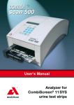
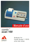
Download Service Manual Analyzer for Combi Screen® 11 SYS urine
Transcript
Service Manual
Analyzer for
Combi Screen® 11 SYS
urine test strips
Service Manual
2
CombiScan 100
State: 30.8.2006, Version: 1.2
CombiScan 100
Service Manual
Contents
1. General information . . . . . . . . . . . . . . . . . . . . . . . . . . . . . . . . . . . . . . . . . . . . . . . . 4
2. Check of operation. . . . . . . . . . . . . . . . . . . . . . . . . . . . . . . . . . . . . . . . . . . . . . . . . 5
3. Check and repair . . . . . . . . . . . . . . . . . . . . . . . . . . . . . . . . . . . . . . . . . . . . . . . . . . 7
3.1 Check and repair of the power supply . . . . . . . . . . . . . . . . . . . . . . . . . . . . . . 7
3.2 Replacement and repair of the LCD . . . . . . . . . . . . . . . . . . . . . . . . . . . . . . . . 8
3.3 Replacement and repair of the printer. . . . . . . . . . . . . . . . . . . . . . . . . . . . . . . 9
3.4 Handling of the driving unit defect. . . . . . . . . . . . . . . . . . . . . . . . . . . . . . . . . 10
3.5 Handling of the optics defect . . . . . . . . . . . . . . . . . . . . . . . . . . . . . . . . . . . . 11
3.6 Repair of the push button panel and cable defect . . . . . . . . . . . . . . . . . . . . 12
3.7 Handling of SW defect. . . . . . . . . . . . . . . . . . . . . . . . . . . . . . . . . . . . . . . . . . 12
4. Spare parts. . . . . . . . . . . . . . . . . . . . . . . . . . . . . . . . . . . . . . . . . . . . . . . . . . . . . . 13
5. Preparation and required instruments . . . . . . . . . . . . . . . . . . . . . . . . . . . . . . . . . 15
6. Error messages, possible reasons and trouble shooting. . . . . . . . . . . . . . . . . . . 16
7. Assembling instructions . . . . . . . . . . . . . . . . . . . . . . . . . . . . . . . . . . . . . . . . . . . .
7.1 Replacement of the assembled upper housing. . . . . . . . . . . . . . . . . . . . . . .
7.2 LCD replacement. . . . . . . . . . . . . . . . . . . . . . . . . . . . . . . . . . . . . . . . . . . . . .
7.3 Replacement of the push button PCB and the connecting cable . . . . . . . . .
7.4 Replacement of printer and panel . . . . . . . . . . . . . . . . . . . . . . . . . . . . . . . . .
7.5 Feeding the printer paper . . . . . . . . . . . . . . . . . . . . . . . . . . . . . . . . . . . . . . .
17
17
20
22
24
26
Contact:
Analyticon Biotechnologies AG
Am Mühlenberg 10
35104 Lichtenfels - Germany
Phone: +49 (0) 64 54 79 91-0
Fax: +49 (0) 64 54 79 91-71
e-mail: [email protected]
www.analyticon.de
3
Service Manual
CombiScan 100
1. General information
This service manual describes the control and repair of the Combi Scan 100. It is
written for use by a well trained service engineer, who is experienced in repairing and
maintaining instruments for diagnostic investigations. The operations, which are described in this manual, should never be carried out by the enduser of the instrument.
The Combi Scan 100 is a precise and costly calibrated optical measurement system.
The listed operations below must be accomplished with special attention and precision. Please take special care to disconnect the device from the power supply if this
is required by the instruction. If spare parts or accessories are needed, it is absolutely
necessary to use only original spare parts for this instrument.
Nevertheless, even a well trained service engineer will not be able to do all operations
to get a defective Combi Scan 100 working again, because for several operations
special equipment is needed. Depending on the problem, it might be necessary to
send the instrument back to Analyticon for repair. More detailed information can be
found in this manual. If a return of the instrument to Analyticon is recommended by
the manual, please contact Analyticon first to agree on the further steps. Never send
the meter back to Analyticon without any written confirmation of Analyticon to do so.
If repair operations are carried out, they are done in the responsibility of the company
who does the repair. If the meter is opened for repair, Analyticon will not take any further warranty for this instrument.
4
CombiScan 100
Service Manual
2. Check of operation
Connect the device to the power
supply
A red LED beside the “START”
button lights up.
No
The power supply feeding of
the device is defected
Check and repair power
supply according section 3.1.
Error message (E1, E3)
Error message description,
section 5.
LCD defect or LCD control
defect
Replacement and repair
of LCD, section 3.2.
No
Printer defect or printer
control defect
Replacement and repair
of the printer, section 3.3.
No
Defect of the driving unit or
the control
Repair of the driving
unit, section 3.4.
No
Printer defect or printer
control defect
Replacement and repair
of the printer, section 3.3.
No
Defective optics or
optics control
Repair of the defect
optics, section 3.5.
No
Defect of the push
button
Repair of the push button
defect, section 3.6.
No
Printer defect or printer
control defect
Replacement and repair
of the printer, section 3.3.
No
Error messages
(E7)
Error message description,
section 5.
Push button defect
Repair of the push button
defect, section 3.6.
Yes
The SW version check number
appears on the LCD, then the
display changes for the main menu
(Worklist, ChkMeas, Menu)
No
No
Yes
Draw paper into the printer (under
the printer cover) (automatic paper
feeding)
Yes
Replace stripholder for a check-strip
holder (with grey strip).
Push ”START” button. The device
starts to measure, and prints out the
result. During the measurement a
white LED will flash, according to the
movement of the strip holder, which
can be seen only from sidewards.
Yes
The printer perfectly prints
(without character error)
Yes
Press button under „Worklist”
(mostleft), the display changes for a
new window (Wl.Next, Wl.Prev, Print)
No
Yes
5
Service Manual
CombiScan 100
No
Press button (mostright) under
„Print”. The stored worklist is
printed. The display will change back
No
to the main menu automatically.
Yes
Push button defect
Repair of the push button
defect, section 3.6.
SW error
SW error handling,
section 3.7.
Error messages
(E7)
Error message description,
section 5.
Push button defect
Repair of the push button
defect, section 3.6.
SW error
SW error SW error handling,
section 3.7.
SW error
SW error handling,
section 3.7.
Error messages
Error message description,
section 5.
SW error
SW error handling,
section 3.7.
No
Problem unsolvable by the
service
The equipment must be
returned for repair.
No
Replacement of the
assembled upper housing.
See section 5.
No
Press button under the
„ChkMeas” (middle). “Check mode
measurement” is diplayd and check
measurement is performed.
The device prints out the result of
the check measurement. „Valid
check” or „Invalid check”.
Then returns to the main menu
automatically.
No
No
Yes
Press the ”START” button. The
display goes back to the main menu.
No
Yes
Press button under „Menu”
(rightmost). Further MENU items
are displayed (Setup, MeasMode,
Memory).
No
Yes
Main units of the device are
operating proper. Different
parameters should be checked
or set (i.e. date, time, language)
according to the user‘s manual.
No
Yes
Visual test: visible damages of the
upper housing, printer cover, plastic
push buttons, plexi plate.
6
CombiScan 100
Service Manual
3. Check and repair
3.1 Check and repair of the power supply
Warning! Never open power supply! If the power supply damaged replace it! Also
replace power cord if any damage is observable!
If there is no visual damage on power supply or
power cord connect the equipment to the power
supply!
CHECK:
1. whether there is a power is on
2. the plug
3. the power cord
4. connections.
5. Measure the output voltage of the equipment!
REPAIR:
1. Set back the line voltage! (Replacement of the fuse!)
2. Another plug must be used!
3. Replacement of the adapter cable!
4. Replacement of the adapter!
If it is less than 7VDC, replace the adapter!
If the defect is still existing and the equipment does
not operate, or such component got damaged,
which cannot be replaced:
the equipment must be returned for repair!
7
Service Manual
CombiScan 100
3.2. Replacement and repair of the LCD
The LCD does not or not properly operate.
The displayed characters are incomplete
CHECK:
1. Check the flex cable of the LCD!
Did it slip out from the socket?
2. Check the LCD
Connect a new LCD without installing it and
check whether the defect is eliminated.
REPAIR
1. Adjust the connection
2. Replace LCD. (see section 7.2.)
If the defect is still exists and the display does not
operate, the LCD control got damaged.
the equipment must be returned for repair!
8
CombiScan 100
Service Manual
3.3. Replacement and repair of the printer
Defects arisen during printing:
• No printing
• Wrong characters are printed
CHECK:
1. Check the printing paper
• Is there paper in the printer?
• Is the paper stuck into the equipment?
2. Check the printer
• Check and move the plugs on the panel
(slipped off or contact defect?
• Check the flexible cable of the printer (did it
slip out?).
• Connect a new printer (section 7.4.) without
installing it, feed the printer by paper and
check whether printing is correct.
REPAIR
1. Repair of the printer paper defect.
Put new paper into the printer and/or insert it
properly
• Take out the stuck paper and insert it properly.
2. Repair of the printer defect.
In case of no socket defect and it cannot be
eliminated by moving it, the printer and the panel
must be replaced.
• Pull out the flexible cables of the printer from
the socket. Check the connector ends (damage,
break, dirt), then plug it again. Check the
operation of the printer.
• If the printing is correct when using the new
printer, replace it.
• If the defect still exists using the new printer,
the equipment must be returned for repair.
9
Service Manual
CombiScan 100
3.4. Handling of the defect driving unit
Driving unit defects.:
• The motor does not operate.
• The strip holder cannot be pushed in.
• It pushes the strip holder out.
• The strip holder is stuck (it moves only inward).
CHECK:
2. Insert a strip holder into the equipment and
connect the power supply to the equipment,
push the „START“ button.
REPAIR:
1. If the defect, arisen during the check or the
operation, does not cease:
• by the replacement of the firmware key (section
7.1.)
• or by the replacement of the strip holder,
• than by a restart
the equipment must be returned for repair!
10
CombiScan 100
Service Manual
3.5. Handling of the optics defect
Optics unit defects.
• The LEDs do not light.
• The CCD does not detect.
• Optocoupler does not operate.
CHECK:
3. Insert a strip holder into the equipment and
connect the power supply, push „START“
button. Watching it from sidewards there
must be a white light flashing up according
to the rhythm of the movement of the strip
holder!
REPAIR:
2. If the defects arisen during the check or the
operation of the equipment do not cease
• by the replacement of firmware key (section 11.)
• then by a restart,
the equipment must be returned for repair!
11
Service Manual
CombiScan 100
3.6. Repair of the push button panel and cable defect
Push button panel and cable defects.
• LED does not light.
• Switches on the PCB do not operate
• Cable is torn, the soldering came off.
CHECK:
4. Insert a strip holder into the equipment and
connect the power supply, push „START“
button. Measurement has to be started.
REPAIR:
5. Replace start- and push button PCB with cable
(UCP-4454-1) with the spare one.
6. If the defect still exists,
the equipment must be returned for repair.
3.7. Handling of SW defect
If defects, arisen during check or operation, do not cease by the replacement of the
firmware key and restart.
The equipment must be returned for repair!
12
CombiScan 100
Service Manual
4. Spare parts
Order Article Denomination
No.
UCP-4451-1 Assembled LCD, with
frame and plastic
shim.
The plastic shim is
only at later models.
Content
Figure
Display, LCD bear
frame
Assembly: section 7.2
UCP-4452-1
Assembled printer,
with panel
Printer, panel, cable
Assembly: section 7.4
UCP-4453-1
Assembled upper
housing
Upper housing, LCD
front panel, printer
cover, push buttons
Assembly: section 7.1
UCP-4454-1
Spare assembled
start- and push
button PCB with
cable
Start-and push button
panel, cables, plugs
Assembly: section 7.3
1ASA7V1A
Power supply type
SA125A-0735U-S
612EPL19
Printer paper
Feeding: section 7.5
13
Service Manual
CombiScan 100
Order Article Denomination
Content
No.
352USBAB
USB cable_type_a-b/1.8 m
14
35200303
Power cord
UCP-4404-1
Assembled strip holder for
CombiScan100
UCP-4405-1
UCP-4414-1
Firmware
Assembled check-strip
holder
UCP-9201-1
UCP-9202-1
User‘s manual
CD
Assembled strip
holder with stuck
test strip
Figure
CombiScan 100
Service Manual
5. Preparation, required instruments, auxiliary material,
labour safety regulations
Cross-grooved screwdriver PH1
Cross-grooved screwdriver PZ1
Straight grooved screwdriver size 4
There are no other labour safety regulations different from the general ones concerning the checking, assembly processes listed in this present Service Manual.
No dangerous material is used.
15
Service Manual
CombiScan 100
6. Error messages, possible reasons and trouble shooting methods
Error Denomination of
code the error
E1
Error in the driving of
the strip holder (“0”
position detection
error).
E3
E4
E5
E6
E7
W1
16
Reasons for the error Trouble shooting
The optical sensor
does not detect the
existence of the
stripholder. Maybe no
stripholder is inserted.
There is no firmware
inserted or firmware
damaged.
Replacement of the strip
holder, if the error is
still existing the device
should be returned for
service.
Insert firmware of the right
Firmware (key-chip)
error.
version into the equipment
to its determined place. If
the error is still existing
the device should be
returned for service.
All connections should
Communication error The serial port/plug
(defect of the serial
or cable are defective be fitted. Try to connect
port or cable).
or the connected unit
to an other device (PC). If
(PC) doesn‘t work.
the error is still existing
the device should be
returned for service.
Load the patient ID block
“Worklist” download Block, longer than 13
error
characters, or patient
up to 13 characters. Check
ID block not loaded up communication with the
to 13 characters
connecting device. If
the error is still existing
the device should be
returned for service.
Data down load from the
Work list memory is
“Worklist full”. The
memory is fully
fully loaded.
memory, clear memory.
loaded.
Printer paper run out
Feed the equipment with
or is missing.
paper. section 7.5.
No data in the
Fill up the memory by
memory to be
some measurements and
try again. If the error is
transferred.
still existing the device
should be returned for
service.
CombiScan 100
Service Manual
7. Assembling instructions
7.1 Replacement of the assembled upper housing (UCP-4453-1)
7.1.1.
Operation
Disconnect power supply.
Remove firmware (under the
printer cover).
Figure
Unscrew the screw
(1 pc PT KA 22x8).
7.1.2.
Turn the equipment upsidedown.
7.1.3.
Unscrew the screws (4 or 5 pcs
PT KA 30x8).
17
Service Manual
7.1.4.
7.1.5.
Operation
Turn back the equipment.
Lift the upper case (upright),
tilt it backward in 180 degree.
Note the position of the cable.
7.1.6.
Unscrew the two screws (PT
KA 25x6) which fix the start
button PCB, pull out the LED
assembled onto the PCB from
the housing.
7.1.7.
Put aside the upper case,
prepare the new one.
Fit LED into the housing (pay
attention to the PCB position),
screw the two screw in (2 pcs
PT KA 25x6).
7.1.8.
18
CombiScan 100
Figure
CombiScan 100
7.1.9.
7.1.10.
7.1.11.
7.1.12.
7.1.13.
Operation
Turn the upper housing onto
the bottom case and holding
it at right angles arrange the
cables (they must not jam
between the two parts).
Service Manual
Figure
Figure according to 7.1.2.
Turn the equipment upside
down.
Screw the screws in (4 or 5 pcs Figure according to point 7.1.3.
PT KA 30x8, 1 pc PT KA 22x8).
Turn the equipment back.
Figure according to point 7.1.1.
Insert the firmware into its
place.
19
Service Manual
CombiScan 100
7.2. Replacement of the LCD (UCP-4451-1)
7.2.1.
7.2.2.
Operation
Disassemble the equipment.
Relase connector fixture
on both end by pressing in
direction as the red arrow
shows.
Pull out the flexibile cable from
the connector.
20
7.2.3.
Unscrew the 2 screws which fix
the button PCB to the frame.
Remove plastic shim.
7.2.4.
Unscrew the screws of the LCD
frame (3 pcs PT KA 25x8.)
Figure
According to points 7.1.1 – 7.1.5.
CombiScan 100
7.2.5.
7.2.6.
7.2.7.
7.2.8.
7.2.9.
Service Manual
Operation
Figure
Replace the frame, assembled
with LCD, fit it to its position.
Figure according to point 7.2.4.
Screw in the 3 pcs screws
which fix the LCD bear frame
(PTKA 25x8).
Figure according to point 7.2.3.
Screw in the 2 pcs screws
which fix the push button panel
to the LCD bear frame (PTKA
25x8)
Connect flexibile cable. First
insert cable into the slot of
the connector. Then fix the
connection by pressing both
end of connector in diraction
shown by the red arrow.
Assemble the equipment.
According to 7.1.9 – 7.1.13
21
Service Manual
7.3
Replacement of the push button PCB and the connecting cable
(UCP-4454-1)
7.3.1.
7.3.2.
7.3.3.
Operation
Figure
Disassemble the equipment.
According to points 7.1.1 – 7.1.6.
Put aside the upper housing.
Unscrew the 2 pcs screw which
fix the push button panel to the
LCD frame.
Remove plastic shim.
7.3.4.
Note the position of the cables.
Disconnect the cable (10p).
(Put aside the panels and the
cables.)
7.3.5.
Connect the connector of the
cable of the spare assembled
push button panels to the
connector of the “main” panel.
Screw in the 2 pcs screws
which fixes the printer panel to
the LCD frame. (2pcs PT KA
25x8)
7.3.6.
22
CombiScan 100
Figure according to point 7.3.4
According to the point 7.3.3
CombiScan 100
7.3.7.
7.3.8.
Operation
Insert the LED of the Start
button into the housing (take
care of the panel position),
screw in the two screws fixing
the panel (2 pcs PT KA 25x6)
Figure
Assemble the equipment.
According to 7.1.9. - 7.1.13.
Service Manual
23
Service Manual
CombiScan 100
7.4. Replacement of printer and panel (UCP-4452-1)
7.4.1.
7.4.2.
24
Operation
Disassemble the equipment
Place the upper housing
behind the lower housing.
7.4.3.
Unscrew the 4 screws which fix
the printer and the PCB, lift the
panel.
7.4.4.
Disconnect both connectors
from the printer PCB. Note the
directions and routing of the
cables! (2p and 16p)
Figure
According to 7.1.1. – 7.1.5.
CombiScan 100
Service Manual
7.4.6.
Operation
Figure
Connect the cables to the
Figure according to point 7.4.4.
spare assembled printer panel.
(2p and 16p)
Place the printer panel onto its
location. Screw in the two short
screws (PTKA 22x6) into the
front holes, then screw in the
two longer screws (PTKA 22x8)
onto the rear.
7.4.7.
Assemble the equipment
7.4.5.
According to the 7.1.9. – 7.1.13.
25
Service Manual
CombiScan 100
7.5. Feeding the printer paper (612EPL19)
7.5.1
7.5.2
Operation
Figure
Open printer cover, insert paper
roll into the holder.
Insert the end of the printer
paper into the slot located at
the rear of the printer.
After it paper feeding goes on
automatically if the device is
turned on.
The edge of the paper must not
be torn or uneven.
7.5.3
26
Close the printer cover, stitch
the end of the paper through
the slot of the cover.


