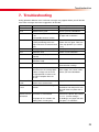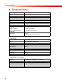
1
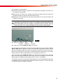
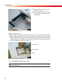
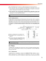
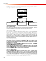
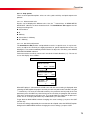
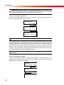
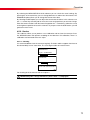
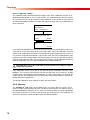
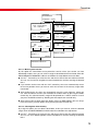
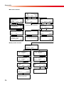
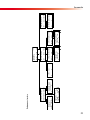
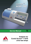
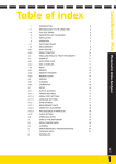
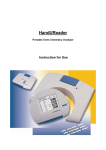
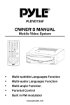
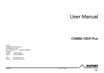
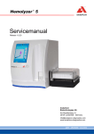
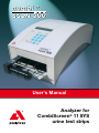
User‘s Manual Analyzer for CombiScreen® 11 SYS urine test strips V4.2.3 revised 3/2009 Contents Contents 1.Introduction........................................................................................... 2 1.1. Methodology of the urine test................................................................................ 2 1.2. The test strips......................................................................................................... 3 1.3. Intended use........................................................................................................... 3 2.Description of the reader..................................................................... 4 2.1. Packing list............................................................................................................. 6 3.Installation............................................................................................. 7 4.Operation............................................................................................... 9 4.1. Switching on/off...................................................................................................... 9 4.2. Overview of the menu system................................................................................ 9 4.3. Worklist................................................................................................................. 10 4.3.1.Add a worklist............................................................................................... 10 4.3.2.Edit a worklist............................................................................................... 10 4.4. Start...................................................................................................................... 11 4.4.1.Mesurement.................................................................................................. 12 4.4.2.Result printout.............................................................................................. 13 4.5. Menu..................................................................................................................... 13 4.5.1.Setup menu.................................................................................................. 13 4.5.1.1. Output settings..................................................................................... 14 4.5.1.1.1. Printer settings............................................................................. 14 4.5.1.1.2. Serial port settings....................................................................... 14 4.5.1.1.3. Language settings........................................................................ 14 4.5.1.2. Strip options......................................................................................... 15 4.5.1.2.1. Measurement units....................................................................... 15 4.5.1.2.2. Sensitivity adjustment.................................................................. 15 4.5.1.2.3. Pad sequence in printout............................................................. 16 4.5.1.3. Clock and date settings........................................................................ 16 4.5.2.Service.......................................................................................................... 17 4.5.2.1. Cleaning................................................................................................ 17 4.5.2.2. Calibration settings............................................................................... 18 4.5.3.Memory......................................................................................................... 18 4.5.3.1. Memory data transfer........................................................................... 19 4.5.3.2. Clearing data from memory.................................................................. 19 4.6. Data download..................................................................................................... 20 5.Care of the instrument........................................................................ 21 5.1. Cleaning of the waste bin..................................................................................... 21 5.2. Cleaning of the conveyor...................................................................................... 21 6.Warnings / Precautions...................................................................... 22 7.Troubleshooting................................................................................... 23 8.Technical data..................................................................................... 24 9.Symbols................................................................................................ 25 Appendix.................................................................................................. 26 1 Introduction 1. Introduction 1.1. Methodology of the urine test The urinalysis is part of the medical diagnosis methods frequently used by medical doctors in laboratories in order to reveal diseases. The most cost-effective device used to screen urine is a reagent test strip. This microchemistry system has been available for many years and allows qualitative or semi-quantitative analysis within one minute by simple but careful observation. The colour change occurring on each test pad of the strip is compared to a colour chart to obtain the result. However, misreading or misinterpreting of results, caused by individual handling habits of the user or different light conditions, may happen. Urine analyzer (urine strip reader) equipment is designed specifically to improve the accuracy and security of urine strip evaluation by using light and photometric reader in order to detect the colour changes on the test strips. The CombiScan® 500 supports test data management and report generation by offering data storage and computerised data processing features. The CombiScan® 500 is a urine analyzer for professional use. The reader is a semi-automatic benchtop instrument designed to read the CombiScreen® 11SYS reagent strips. The operator needs only to feed the equipment by placing the moisturised strip on the conveyor – the rest, as forwarding, reading, evaluating and disposal of the strips is done automatically by the device. The timing (route-length and speed of the conveyor belt) is adequate to the incubation time of the test strip. The CombiScan® 500 analyses the colour and intensity of the light reflected from the reagent surface and reports the results in clinical meaningful units. No further calculation is needed by the user. When a strip is moved into the measuring position under the optical unit, the reflectance of each reagent pad is measured. The light reflected at specific wavelenghts from the test pad depends upon the degree of colour change of the pad, which is related to the concentration of the particular parameter in urine. The intelligent image analyzer software first detects, locates the strip and the pads, then, based on these colour light-wave information the CombiScan® 500 reads the reagent areas and the values are calculated automatically. Results are stored, then printed out by the built-in printer and can optionally be sent to host computer via serial connection. 2 Introduction 1.2. The test strips The base of the urine analysis is the good quality of the urine test strip. These strips have separated pads for each parameter. The test pads contain reagents, which cause colour changes according to the parameter concentration in the urine. The CombiScan® 500 is calibrated to CombiScreen® 11SYS urine test strips and guarantees accurate results all time. The CombiScreen® 11SYS urine test strip contains reagents for testing: Bilirubin Urobilinogen Ketones Ascorbic Acid Glucose Protein Blood pH Nitrite Leukocytes Specific Gravity Besides the CombiScreen® 11SYS, the CombiScreen® 11SYS PLUS can also be used with this instrument. To facilitate reading of the manual, the test strip is always named CombiScreen® 11SYS in this manual. IMPORTANT! Before using the test strip read carefully the CombiScreen® 11 SYS packing insert! The meter can only be used with the CombiScreen® 11 SYS urine test strip! 1.3. Intended use CombiScan® 500 is an instrument for measurement of urine test strips CombiScreen® 11SYS for in-vitro determination of Ascorbic acid, Bilirubin, Blood, Glucose, Ketones, Leukocytes, Nitrite, pH, Protein, Specific Gravity and Urobilinogen from urine. These measurements are used in the evaluation of diabetes, liver diseases, haemolytic diseases, urogenital and kidney disorders or metabolic abnormalities. For professional use, not for self testing. 3 Description of the reader 2. Description of the reader The equipment is designed specifically for use in clinical laboratories. In its basic installation the housing is almost fully closed, its physical appearance including colour meets the requirements raised by medical laboratories. Its throughput is about 500 test strip evaluations/hour. LCD Controll Keys Numeric Keys Function Keys Fig. 1 Front Waste-bin Fig.1 Front view of the CombiScan® 500 urine analyzer Rear Shaft Cylinder 1 Cylinder 2 Due to the CCD-technology, the instrument is able to distinguish between colour changes caused by reaction of the test pad chemistry and non-specific colour development, caused by the sample. Support Front Shaft Fig. 2 Carriage Strip Pumper Belts Fig. 2 Description of the parts for installation 4 The optical system is designed especially for evaluation of urine test strips. The test strip is illuminated by white light and the reflected light from the reagent strip is detected by a colour CCD sensor. The signals are digitalized and this digitalized image is evaluated by the built-in program. Operation is very simple, and doesn’t require any special knowledge or difficult practice. When measurement starts, the front door opens and the conveyor assembled onto a carriage moves into the measuring position. The strip needs to be placed on the conveyor. Both the conveyor and the carriage are driven by a DC motor. Description of the reader The carriage has three positions: Closed: The whole carriage is inside of the housing and the Frontdoor is closed. This is the stand-by or off position. Measurement: The front of the carriage is ejected of the reader housing in order to let the operator place the strip onto the three-belt conveyor. Maintenance: The carriage is fully ejected. In this position you can remove the belts and cylinders for cleaning. CAUTION! The carriage movement is controlled by the reader, never try to move it manually, not even when the reader is in stand-by or turned-off position! If the power shuts down when the carriage is ejected or an error occures, turn the reader off and on. The carriage will find its normal position automatically. Fig. 3 DC connector Keyboard Interface RS232 Serial Port Slot Firmware Fig. 3 Rear view of the CombiScan® 500 urine analyzer The used strips are collected in a waste bin located under the conveyor inside the CombiScan® 500 (capacity: about 150 strips). If the automatic strip-counter reaches 150 you will get a warning message which asks you to empty the waste-bin. To remove the wastebin just push and release its front panel. It will be automatically ejected. Pull it out totally, empty it and insert it back. Slip it gently till it is bumping (see section 5.1.). On the top side of the CombiScan® 500 you can find the built in printer. If you open the printer cover by lifting it’s front side you will get access to the paper roll cave to load printer paper. For loading the printer paper refer to section 3 (Installation). The interface connectors are located on the back panel. The external barcode reader and/ or keyboard can be connected to the keyboard interface connector. The host computer can be connected to the RS232 serial port. 5 Description of the reader 2.1. Packing list 6 CombiScan® 500 instrument 1 pc cylinder 1 1 pc cylinder 2 (with gearwheel) 1 pc belt 6 pcs power adapter 1 pc power cord 1 pc serial cable 1 pc users’ manual 1 pc printer paper 1 roll CD 1 pc (optional) Installation 3. Installation The CombiScan® 500 is shipped in a carton box. Prior to unpacking, clear the area where the instrument is to be operated, a surface of about 30x50 cm will be needed. While handling the package, please be cautious of the shipping marks on the box. Open the box. Cut the tape only, leaving the carton material intact. It is recommended to keep the packing materials for a while as well, in case the instrument needs to be moved to another location or must be shipped to have it been repaired in the manufacturers’ service. Check the packing list, if the shipment is complete (see section 2.1.). If it is complete follow the instruction below otherwise please contact your distributor immediately. Place the CombiScan® 500 to its working position. Optional: Connect the CombiScan® 500 to your computers’ serial port, by using the serial cable, if necessary. Optional: Connect your keyboard or barcode reader optional to the interface connector. Connect the power adapter first to DC connector then to the mains. Switch the reader on by pressing ENTER on the built-in keypad. In a few seconds the actual software version appears for a short moment on the LCD. „CLEAR MEMORY“ appears on the display. Press QUIT. Now you reach the MAIN MENU. Select MENU by pressing the control key below the MENU sign. Select SERVICE by pressing the control key. Select CLEAN by pressing the control key. Now the door opens automatically and the conveyor section moves out until the cleaning position is reached. Front Shaft Install the cylinder 2 (with the gearwheel) onto the rear shaft until the built in magnet fixes it in the proper position (see fig. 4). Rear Shaft Install the cylinder 1 onto the front shaft until the built in magnet fixes it in the proper position (see fig. 4). Strip Bumper Fig. 4 Fig. 4 Installation of the cylinders 7 Installation Install all the three belts onto the cylinders (see fig. 5). Press the OK key. Now the conveyor slips back and the door closes automatically. Fig. 5 Fig. 5 Installation of the belts Open the printer cover. Take the roll of printer paper and insert the roll into its cave. Load the free end of the paper into the feeding slot in a way, that the outer side of the paper roll is facing down while inserting it into the feeding slot (if the paper is inserted in the wrong way, there will be no printout on the paper). The paper will be loaded automatically (see fig. 6). To remove the paper, just pull out from top side. Printer Cover Printer Paper Printer Fig. 6 Fig. 6 Loading the printer paper Now, the CombiScan® 500 is ready to work. Note: Before the first measurement a calibration process should be done (see section 4.5.2.2.)! 8 Operation 4. Operation 4.1. Switching on/off Connect the CombiScan® 500 with the power adapter to a power socket. Press the ENTER button if the instrument is in standby mode. The name and software version of the instrument is displayed on the LCD for a short time. Now, one of the following alternative options will be executed depending on the stored “working history“ of the reader. The strip counter is not equal to zero. This means that measurements were done since the last waste bin emptying. If you empty it now, press the „YES“ control key and the strip counter will be set to zero. If you do not clear the waste bin from used strips now, select „Cancel“. In this case the strip counter will not be reset. If there are measurement results stored in the memory at the day’s first power-on, the programm will offer an option of deleting the memory content. CAUTION! If you select „OK“ all data stored in memory will be erased! Chose this option only if data have been archived, printed out or you are sure you don‘t need them any longer! If the memory is free and the used strip counter is set to zero at the day’s first power on, the MAIN MENU appears on LCD. 2004/08/09 >>004 <<005 WORKLIST 19:19:26 Combi Scan 500 V.4.01.05 START MENU If you want to switch off the reader, just press the QUIT button. Answer YES when the reader asks for confirmation. Now the CombiScan® 500 is in standby mode. 4.2. Overview of the Menu system The equipment is controlled by a multilevel menu system. The bottom line of the four-row LCD indicates the actual selectable menu items – max. 3 at the same time. These menu points can be selected by pressing the control key right below. Without any selection you will get back to the main menu by pressing the QUIT button. 2004/08/09 � 004 � 005 WORKLIST 2004/08/09 19:19:26 MENU/WORKLIST ITEM Nr: 0 EDIT/ADD CLEAR PRINT MANUAL � 001 � 000 SKIP 19:19:26 Combi Scan 500 V.4.01.05 START MENU CombiScan500 STOP 2004/08/09 MENU SETUP SERVICE 19:19:26 MEMORY 9 Operation 4.3. Worklist The worklist is a predefined sequence of samples. The worklist contains maximum 128 patients ID’s in the sequence of planned evaluation. A worklist can be generated through a connected external keyboard or barcode reader. The patient ID is a maximum 13 character long string containing either numeric or alphabetic characters. If the worklist is entered through the internal keyboard, only numeric characters are possible. If you wish to delete an ID from worklist it can be done in the MENU/WORKLIST/CLEAR submenu. 2004/08/09 � 004 � 005 WORKLIST 19:19:26 Combi Scan 500 V.4.01.05 START MENU 2004/08/09 19:19:26 MENU/WORKLIST ITEM Nr:6 EDIT/ADD CLEAR PRINT EDIT/ADD WORKLIST LIST ITEM: 001 EDIT ID: MILLER JOHN � � BACK 2004/08/09 19:19:26 MENU/WORKLIST/CLEAR ITEM ALL CLEAR WORKLIST ITEM: 001 Nr: 6 ID: MILLER JOHN � � CLEAR 4.3.1. Add a worklist The worklist can be entered by the internal keypad, an external keyboard or barcode reader. Connect the keyboard or barcode reader to the keyboard interface connector of the CombiScan® 500 and press the left control key of the CombiScan® 500 to get to the worklist menu. In the EDIT/ADD worklist-submenu, a name or a patient ID of up to 13 characters can be typed or read in. If you have finalized one name or patient ID, press enter to go to the next ID. When using a barcode reader, you automatically jump to next ID after you have entered a new ID. To go back to the main menu press the QUIT button. If you press the BACK control key you will come back to worklist menu, where you can print out the worklist. If you wish to start the measurement of the first ID of the worklist quit the worklist menu and start measurement from main menu. 4.3.2. Edit a worklist A compiled worklist can be edited as well. You can edit the IDs, add new items or remove single items or the whole worklist. Inserting a new item into an existing queue is not allowed. To use the worklist features follow the flowchart shown above. From MAIN MENU you can enter the worklist menue by selecting “WORKLIST”. If there is no existing worklist the ADD text is displayed on the LCD left side, otherwise EDIT. By selecting EDIT/ADD option you can modify the patient ID data and/or enter new items. In the WORKLIST/CLEAR submenu single items or the whole worklist can be deleted, and in WORKLIST/PRINT submenu the worklist can be printed out. After pressing EDIT/ADD control key the worklist appears. Using the arrow keys you can navigate through the worklist. If you want to modify a patient ID, use the DEL function key 10 Operation of the internal keypad to delete the last characters. To confirm the new entered ID press ENTER. The next worklist item will appear. Reaching the last item of the worklist ADD will appear on the display. Now you can enter new items to the list. If the number of worklist elements reaches the limit the “FULL” text will be displayed instead of the patient ID. To get back to MAIN MENU select BACK option and than press the ENTER function key of the keypad. To remove items from the worklist select CLEAR option. In the WORKLIST/CLEAR submenu you can delete the whole worklist by selecting ALL, or just delete individual items by pressing the ITEM control key. There you can select the desired item using the control keys. Pressing OK the item will be deleted. To go back to MAIN MENU press QUIT function key. 4.4. Start The reader can evaluate only the CombiScreen® 11SYS test strips. There is a calibration card enclosed to the strips. Each calibration card has an individual code. This code authorises the reader to read the strip. To read more about calibration see section 4.5.2.2. Users should always follow the appropriate federal, state, and local guidelines concerning the use of external quality control materials. There is no further special operation needed to calibrate the instrument before starting the daily routine urinalysis. It is recommended to use urine controls at least daily to check the system. It is possible to make measurements in sequence of samples or according to prepared worklist. If a worklist is stored in the reader „WORKLIST“ is indicated in the START menu on the left side of the first row of LCD (see below). Otherwise „MANUAL“ is displayed (see below). To learn more about the worklist refer to section 4.3. By selecting START the door will open and the conveyor will move out to be ready for measuring the samples. To stop operation press the STOP control key. The conveyor will stop running and slips back in “off” position and the door will close. The MAIN MENU will be displayed again. IMPORTANT! The reader will only stop operating if the conveyor is empty! The STOP command will only be accepted if the last strip detection and evaluation is over. If there is no strip detected for 5 minutes a STOP function will be executed automatically. During operation the following informations are displayed on the LCD: WORKLIST Combi Scan 500 � 001 MILLER, JOHN � 000 SKIP STOP or MANUAL � 001 � 000 SKIP Combi Scan 500 12345678 STOP 11 Operation 4.4.1. Measurement The day-to-day operation of the CombiScan® 500 is easy, and will be guided by the following lines. Have the urine test sample tubes prepared. Press the START control key. Insert an unused strip into the urine specimen, rinse it at the edge of the container, briefly dap the edge of the test strip on a tissue paper and place it on the conveyor with the test pads upside. Push the strip gently till it bumps against the strip-bumper. The strips must be positioned at right angles to the conveyor (see Fig. 7a, 7b). However, the system is able to compensate slight deviations. From this moment the testing process is controlled automatically by the CombiScan® 500. Fig. 7a Fig. 7b Fig. 7: Positioning of the reagent strip. Fig. 7a shows the right positioning. Fig. 7b shows a wrong position. If you are in „MANUAL“ mode, you can enter a alphanumeric, max. 13 digit patient ID to be assigned to the next strip. You can enter the digits via the built-in numerical keypad or by using a barcode reader or external keyboard. Using the WORKLIST mode the next patient’s ID appears in the second row of the LCD. When a strip has been evaluated, the results are sent to the serial port. If a computer is connected to the reader, the data can be stored and displayed with the Analyticon CombiScanner Data Management software (see also section 4.6.). If the build-in printer is turned on, the results are printed out, too. After dipping the urine strips into the sample they can be placed on the conveyor. In a minimum distance of approximately 3cm to the prior strip. This allows a throughput of about 500 strips per hour. If you would like to skip a patient ID from the worklist, just select the “SKIP” option and the reader will delete the element and jump to the next item of the worklist or sequence number in manual mode. If during the work you reach the preprogrammed measurement counts (defined by the calibration card), a warning message will be printed. In this case you are still allowed to go on measuring an additional 1% of the named counts. Finish your work and perform a calibration process with a new calibration card (see section 4.5.2.2.). If you do not calibrate the instrument, it stops working until a new calibration is performed. After having finished your daily routine press the “STOP” key. The conveyor will stop running. Clean the instrument and emty the waste bin (see section 5.). 12 Operation Note: The following error messages may appear during the measurement process. „The waste bin is full!“ This message is accompanied by a short beep. It means that the waste bin has not been emptied for 150 measurements. Interrupt the measurement process and empty the waste bin, then continue working. “The waste bin is out!“ This message is accompanied by a short beep. It means that the waste bin is not in the right position. Maybe it wasn’t slipped back completely after emptying, or it has been opened accidently. Note: All instructions must be followed thoroughly to get accurate results! 4.4.2. Result printout The printed/sent results contain the following data: device type, date and time, sequence number of the test, patient identifier, result with analyte names, values, units, markings for pathological values and an end line. Before each parameter name the pathological value is marked with an asterisk (*). If one or more result classification limits (see section 4.5.1.2.2. for changing sensitivity) have been changed, the bottom line of result starts and ends with an asterisk (*----*). Each classification range has a name and a unit, corresponding to the analyte. Date Sequence Nr. given by the reader Patient ID Values are displayed in conventional units Pathological values are marked with an asterisk (*). If one or more result classification limits have been changed, the bottom line of result starts and ends with an asterisk (*----*). Note: The printing on thermal paper may fade during storage, or if it is covered with transparent tape. 4.5. Menu The MENU offers the opportunity to adjust the instrument according to individual requirements, and to manage the data in memory. To carry out operations, select the MENU option in the main menu. 4.5.1. Setup menu The SETUP menu is adapted to customize the CombiScan® 500 according to your individual requirements or working methods. By selecting this menu, you can configure the communication with your host computer, the built-in printer and the printout format 13 Operation including the result units, the sensitivity of different pads, etc. To get familiar with these features please follow the flowchart below: 2004/08/09 � 004 � 005 WORKLIST 19:19:26 Combi Scan 500 V.4.01.05 START MENU 2004/08/09 MENU SETUP 19:19:26 SERVICE 2004/08/09 MENU/SETUP OUTPUT STRIP MEMORY 19:19:26 CLOCK 2004/08/09 19:19:26 MENU/SETUP/OUTPUT 2004/08/09 19:19:26 MENU/SETUP/STRIP 2004/08/09 19:19:26 MENU/SETUP/CLOCK PRINTER SERIAL LANGUAGE UNIT SET SENS. PADSEQ 12/24 SEQUENCE 4.5.1.1. Output settings In this submenu you can set the printer, the serial port and select the language. Select the desired function by pressing the buttons below the displayed menu items. 4.5.1.1.1. Printer settings In this submenu you can check and adjust the printer settings. By pressing the ON/OFF key the status of the printer can be changed. In off-position the results will be stored in memory and send to the serial port. In order to secure the permanent printout quality there is a built-in option to adjust the contrast in a range of 0-3 by pressing the CONTRAST control key. In this way you can compensate varying paper quality. Pressing the CONTRAST control key will change the contrast up by one degree. Reaching the highest contrast (+3) the program will return to 0. 4.5.1.1.2. Serial port settings Setting up the serial line is needed only if the CombiScan® 500 is connected to a computer. Connect the serial cable to the computer only, if the reader is switched off. The following protocols can be selected: PC unidirectional for use of the CombiScan® 500 with a host computer with the CombiScanner Data Management software installed. All other protocols (Labureader, MT1, MT2, CL) are bidirectional protocols. They are needed if the CombiScan® 500 is used in a network environment. For more information about using the CombiScan® 500 in a network contact your distributor. 4.5.1.1.3. Language settings Basically CombiScan® 500 supports five languages: English, German, Hungarian, French, and Spanish. Selecting this submenu use the keys to select the desired language. Press the OK control key to confirm the selected language. In the printout, Chinese characters can be selected instead of normal characters. If you want to print out the parameter name in Chinese characters press the “1” numeric key of the keypad. In the same way you can disable this function. The current setting is displayed on the LCD. 14 Operation 4.5.1.2. Strip options There are three possible options to be set: units, pad sensitivity and pad sequence on printout. 4.5.1.2.1. Measurement units Results can be displayed in different units. Use the control keys in MENU/SETUP/ STRIP/UNIT submenu to select the desired unit. The CombiScan® 500 supports the following measuring units: Conventional SI Arbitrary Conventional + Arbitrary SI + Arbitrary 4.5.1.2.2. Sensitivity adjustment The CombiScan® 500 provides semiquantitative results. In special cases, it may be necessary to adjust the sensitivity of single parameters to special requirements of the user, although it is not recommended by ANALYTICON. To adjust the sensitivity, enter MENU/ SETUP/STRIP/SENS submenu. Pad measurement sensitivity can be set in two levels in both directions (+/-). The set values on the display are as follows: – – 0 – 0 0 0 + 0 + + 2004/08/09 19:19:26 MENU/SETUP/STRIP UNIT SENS. PADSEQ. PAD SENSITIVITY DEFAULT/USER DEFINE DEFAULT SET PAD SENSITIVITY PAD NAME: BIL SENSITIVITY: 0 QUIT NEXT When SET option is selected the first PAD name with the actual setting is displayed. After selecting the SET option the proper sensitivity of each test pad can be selected, using the control keys. To enter the selected sensitivity of a parameter and to jump to the next parameter, press the NEXT key. After having set the sensitivity, the program will automatically return to the previous function menu. It is not possible to escape until all pad sensitivities are set. To skip a pad without any modifications just select NEXT. To get back to MAIN MENU without changing the actual settings, just press the QUIT function key. To reset the settings adjusted by the manufacturer for all pads select the DEFAULT option. Going back to MAIN MENU without changing the actual settings, just press QUIT. 15 Operation IMPORTANT! The adjustment of the pad sensitivity effects the results of the measurement! When the reader is adjusted different from manufacturer setting it will be indicated by asterisks in the footer of the printout! 4.5.1.2.3. Pad sequence in printout By default, the reader prints out the result in the sequence of the pads physical position but it is also possible to customize the layout. 2004/08/09 19:19:26 MENU/SETUP/STRIP UNIT SENS. PADSEQ. PAD PRINTING SEQUENCE DEFAULT/USER DEFINE DEFAULT SET QUIT PAD PRINTING SEQUENCE REPORT LINE: 01 PAD NAME: BIL NEXT This setup option effects only the printout and data transfer! If the PADSEQ option is selected, you can restore either the default sequence or set up your own sequence by selecting the SET option. Selecting SET you can choose pads in a desired sequence of the printout lines. In the second row the line number is displayed and the third line indicates the actual parameter name. Using the control keys you can perform changes. Pressing the NEXT option will display the next printout line. If you select “End rep.” only the previously selected parameters will be printed out. When the last line is reached, the program returns to PADSEQ submenu. NOTE: You can not define empty printout lines or the same parameter twice or more times. 4.5.1.3. Clock and date settings The built-in digital clock enables to store the date and time of the measurement. It is working even if the reader is turned off or the power supply is not connected. The reader supports different date and time formats. 2004/08/09 MENU/SETUP OUTPUT 19:19:26 STRIP CLOCK 2004/08/09 19:19:26 MENU/SETUP/CLOCK SET 12/24 SEQUENCE 2004/08/09 19:19:26 ENTER NEW DATE & TIME >>> 16 � � Operation By selecting the MENU/SETUP/CLOCK submenu you can check the actual settings. By pressing the 12/24 control key you can change between 12 and 24 hour time format. The SEQUENCE option allows you to change the format of the date. By selecting the SET option you can adjust the correct date and time. In this submenu use the >>> control key function pad to move the cursor to the position you want to change. Enter the correct numbers with the internal keypad or the control keys. Move the cursor to the rightmost position to leave this submenu. If you press now the QUIT button, you will get back to main menu. 4.5.2. Service This submenu allows you to perform a new calibration and to clean the conveyor. Press the SERVICE button and operate according to the flowchart. For calibration, there is a calibration card enclosed to the test strips. 4.5.2.1. Cleaning It is recommended to clean the conveyor regularly. The belts and the support shaft have to be cleaned daily or even more often, in case of high number of measurements. 2004/08/09 MENU/SERVICE CLEAN 19:19:26 CALIBRATION PLEASE WAIT... CLEAN THE CONVEYOR BELT! OK For cleaning of the instrument refer to chapter 5. NOTE: During the carriage movement „Please wait…“ is displayed. 17 Operation 4.5.2.2. Calibration settings The calibration card is delivered with the reagent strips. Each calibration card has an individual barcode printed on it. This code contains test strip related data and the number of measurements that can be carried out after calibration. If the number of measurement exceeds the predefined number, the reader will stop measuring, and a new calibration has to be carried out. 2004/08/09 MENU/SERVICE CLEAN 19:19:26 CALIBRATION PLACE CALIBRATION CARD, OR ENTER 1ST BARCODE! MANUAL CANCEL MANUAL CALIBRATION Code: CANCEL If you select CALIBRATION, the conveyor will move to measurement position, but the conveyor will run faster than it does in the measuring modus. Place the calibration card with the bar code upside on the conveyor. It must be placed at right angles to the conveyor in a way, that the angle with the barcode is close to the meter. Place the card behind the strip bumper close to the carriage. Before reaching the optical unit the conveyor will slow down and the sensor reads the code. The conveyor starts to move in reverse direction delivering back the calibration card. The stored calibration data will be printed out. CAUTION! Don‘t throw the calibration card away before the package of strips is completely consumed! If the calibration wasn‘t successful or you want to do the calibration manually, select MANUAL. The conveyor will move back into the housing. Now you can enter the 16 digit number which is printed below the first barcode. As soon as all numbers are entered, the code evaluation and calibration process takes place automatically. Details of stored calibration data will be printed out. To interrupt calibration select CANCEL or press the QUIT button. 4.5.3. Memory The CombiScan® 500 stores the last 999 results in memory. With the results, the sequence number, entered patient ID, time and date of measurement are stored as well. In this MENU/MEMORY submenu you can clear results from memory or transfer stored data to the built in printer or to a device connected to the serial port (i.e. host computer). To achieve the functions mentioned above follow the flowchart below. 18 Operation 2004/08/09 MENU/MEMORY TRANSFER 19:19:26 CLEAR TRANSFER REPORTS � 036 1234567890123 040 2004/08/11 � � OK CLEAR MEMORY � 036 1234567890123 040 2004/08/11 � � OK TRANSFER REPORTS 036 4110100135674 � 040 2004/08/11 � � OK CLEAR MEMORY 036 4110100135674 � 040 2004/08/11 � � OK TRANSFER REPORTS 036 040 PRINT SEND CLEAR MEMORY 036 040 OK BACK TRANSFER IN PROGRESS... REPORT: 5 BACK MEMORY CLEAR... CANCEL TRANSFER COMPLETE! 4.5.3.1. Memory data transfer By this option the stored data can be printed or send to a host (see section 4.5. Data download). In both cases you can select a range of stored data to be transferred. Enter the MENU/MEMORY/TRANSFER submenu and follow the steps below to transfer data: Use the control keys to select the first and the last item of the row to be transferred. You can use the numeric keypad or external keyboard as well for entering the desired items. If you confirm the first item with the “OK” control key the curser automatically moves to the next position where you have to enter the last item of the memory range to be transferred. After confirming the last item you automatically reach the next submenu, where you can select the device to which you would like to send the data. By pressing the PRINT control key, the selected memory range will be printed out. It will be send to a host if you press the SEND control key. Sending the data require few seconds only. After transmission has been done the display returns to MAIN MENU. You can always leave the memory transfer option when pressing the QUIT function key. 4.5.3.2. Clearing data from memory By using this option you can delete stored data. At first you have to select the desired range. Enter the MENU/MEMORY/CLEAR submenu and follow the steps below: Use the control keys to select the first and the last item of the row to be transferred. You can use the in-build keypad or external keyboard as well for entering the desired items. 19 Operation If you confirm the first item with the “OK” control key the curser automatically moves to the next position where you have to enter the last item of the file to be deleted. After confirming the last item you automatically reach the next submenu, where you can start deleting by pressing the “OK” control key. If you press the “BACK” control key you will return to the previous menu, where you can modify the selected range. After clearing data from memory the CombiScan® 500 returns to MAIN MENU. You can always leave the memory clear option by pressing the QUIT key. 4.6. Data download The results of measurements can be downloaded to a host computer by using the CombiScanner Data Management software. You can find the software on the CD which is delivered together with the instrument. IMPORTANT! The data will be stored on a computer only if the measurement refers to a patient ID which has been added to the worklist (see section 4.3.1.)! System requirements: Hardware: Processor: Pentium III 300Mhz Memory: 256 MB RAM Hard disk: 300 MB HDD Monitor: 1024*768 color Software: Windows XP, Windows 2000 or Windows 98 Microsoft Internet Explorer 5.01 or higher Installation: 1.Install the CombiScanner Data Management software on your computer. Please carefully read the readme.txt on CD first and follow the steps for software installation. 2.Switch off the CombiScan® 500 and connect it with a serial cable to the host computer. Then switch on the instrument again. 3.Adjust the CombiScan® 500 as follows: MENU/SETUP/OUTPUT/SERIAL/PROTOCOL to PC unidir. with a baud rate of 9600. 4.Open the CombiScanner Data Management program and follow the instructions in Help menu (User’s guide). See also chapter 4.5.3.1. “Memory data transfer”. Make sure that the baud rate of the selected port of the computer is adjusted to 9600. 20 Care of the instruments 5. Care of the instrument Operation of the CombiScan® 500 does not require any special maintenance. Only the cover, waste bin and conveyor of the instrument have to be cleaned and disinfected regularly. It should be done always after severe contamination, at least daily. Cleaning should be performed with a wet cloth and/or alcohol. 5.1. Cleaning of the waste bin The used strips are collected in the waste bin (max capacity approx.150 strips), which is located under the front door of the conveyor (see fig. 1). As soon as the automatic strip counter has reached 150, the demand to empty the waste bin appears on the LCD. To open the waste bin, slightly push the front side under the conveyor. The waste bin will move out automatically. Now you can take out the case, empty the strips and clean and disinfect the bin with water and alcohol or disinfetant, respectively. Move the waste bin back into the CombiScan® 500 and push it in carefully until it locks in place with a “click”. 5.2. Cleaning of the conveyor It is recommended to clean the conveyor regularly. Cleaning of the driving cylinders is necessary weekly or if contaminations are visible on the cylinders and carriage. The belts and the support shaft have to be cleaned daily or even more often, in case of high number of measurements. Please clean the conveyor as follows: Press the „CLEAN“ control key in the MENU/SERVICE submenu to bring the conveyor in cleaning position. Remove all three belts and if necessary also the cylinders. Clean the shafts and support by using a wet cloth. Clean the pieces either under running water or alcohol or disinfetant. Dry them completly and make sure that the inside of the cylinders is dry before putting them back onto the shafts. After the cleaning process is finished replace the belts and cylinders and press “OK” The display return to „SERVICE“ menu. To get back to „MAIN MENU“, press the QUIT function key. NOTE. During the carriage movement „Please wait…“ is displayed. 21 Warnings / Precautions 6. Warnings / Precautions The CombiScan® 500 must be used in the manner described and specified in this manual in order to provide the saftety and performance standards specified. The instrument is calibrated for CombiScreen® 11SYS test strips. With other CombiScreen test strips or with test trips of other manufacturers, wrong results will be obtained. In order to establish a final diagnosis and prescribe an appropriate therapy, the results obtained with CombiScan® 500 should be verified with other medical and diagnostic results. To check the performance of the system (instrument+test strips) and to ensure reliable results, it is recommended to use control solutions regularly and to record the results. Especially in the following situations, the use of urine controls is highly recommended: a)at the beginning of the daily routine measurements b)if a new bottle of test strips is opened c)if test results are in doubt d)if operators are trained on the system Urine samples should be handled as a potentially infectious liquid. The equipment which comes into contact with urine, should be disinfected thoroughly after having finished working. Always apply safe laboratory practices when operating the CombiScan® 500 The CombiScan® 500 is an electrical device. Take care that no liquids like water, urine or disinfectants enter the instrument, because this may damage the device or may lead to a dangerous situation for the user. Do not open the housing of the CombiScan® 500 when connected to power supply. In case of problems, call your distributor. Protect the instrument from extreme temperatures or high atmospheric humidity, and keep it out of bright light! For measuring, keep the specifications concerning temperature (15 – 30°C) and relative atmospheric humidity (<85%). 22 Troubleshooting 7. Troubleshooting During operation different errors and error messages may appear. Below you will find the list of error messages and some suggestions what to do: Error Error source Solve the problem E-11----E-17 Hardware error. Contact your local distributor E-18 CMOS memory error Contact your local distributor E-19 Hardware error (Firmware ERROR Upgrade with an invalid firmware. E-19 Try again with a valid one Incompatible firmware version E-21..E-22 Improper test performance due to false positioning of the test strip or because of contaminated belts. Clean the conveyer belts and perform the test again. Take care of the strip position (see section 4.4.2.). E-25 Missing strip or improper strip Use a proper test strip E-31 Calibration error Perform a new calibration E-33 Barcode error (improper barcode entered) Enter a valid barcode E-41 Validity calibration error (expired calibration card) Perform a new calibration E-51 Data communication error Check connection cable or the communication settings E-60 Carriage mechanical error. Some obstruction on the carriage path, and the carriage can not reach the right position. Incorrect control signal reception from the sensor. Disconnect and reconnect the power supply. If the error stands, contact your local distributor. “The waste bin The waste bin has not been emp- Empty the waste bin. is full” tied for 150 measurements. “The waste bin The waste bin is not in the right is out” position. Move the waste bin back into the CombiScan 500 and push it carefully until it locks in place with a “click”. Results are not The Printer is switched off. printed out Switch on the printer. See section 4.5.1.1.1. „Printer settings“. The paper roll is inserted in the feeding slot in a wrong way. For loading a new paper roll refer to chapter 3 “Installation”. 23 Technical data 8. Technical data methodology reflectance photometer detection CCD image processing max. throughput 500 strip/hour memory last 999 results display 4 x 24 character LCD printer 57 mm thermal printer (2 lines/sec) size 480 x 305 x 190 mm weight 10 kg external power-adapter 7,5 V DC / 3A Interfaces: RS232 serial port host communication AT/PC keyboard interface (DIN5 pole) keyboard, barcode reader environment 15–30°C < 85% rel. atmospheric humidity Factory settings: Date YYYY / MM / DD Time HH / MM / SS (24-hour mode) Printer ON Sensitivity Default Pad Sequence Default Unit Conv Protocol PC unidir. Speed 9600 Language English Memory Cleared List of spareparts / consumables: 24 A93100 CombiScreen 11SYS (pack size 100 pcs.) A94100 CombiScreen 11SYS Plus (pack size 100 pcs.) A93010 Paper for thermal printer (57 mm x 25 m) 56175x03 Rubber belt (1 pc.) 1ASA7V1A Power adapter Symbols 10. Symbols In vitro diagnosticum Warning Read package insert SN Serial number Manufacturer This product is conform to the directive 98/79EG dated 27.10.1998 For members of the European Union only: According to Guideline 2002/96/EC (WEEE), this instrument must be recycled profes sionally. Please return it to your distributor at the end of the economic lifetime. Tested to comply with FCC standards For home or office use ANALYTICON BIOTECHNOLOGIES AG 35104 Lichtenfels Germany Phone: +49.64 54.79 91-0 Fax: +49.64 54.79 91-30 [email protected] www.analyticon-diagnostics.com 25 Appendix Main menu structure 2004/08/09 � 004 � 005 WORKLIST 19:19:26 Combi Scan 500 V.4.01.05 START MENU 2004/08/09 19:19:26 MENU/WORKLIST ITEM Nr: 0 EDIT/ADD CLEAR PRINT MANUAL � 001 � 000 SKIP EDIT/ADD WORKLIST LIST ITEM: 001 EDIT ID: MILLER JOHN � � BACK see Setup menu structure 2004/08/09 19:19:26 MENU/WORKLIST/CLEAR ITEM CombiScan500 STOP SETUP SERVICE 2004/08/09 MENU/SERVICE CLEAN CLEAN THE CONVEYOR BELT! 2004/08/09 MENU/MEMORY CLEAR CLEAR MEMORY � 036 1234567890123 040 2004/08/11 � � OK TRANSFER REPORTS 036 4110100135674 � 040 2004/08/11 � � OK CLEAR MEMORY 036 4110100135674 � 040 2004/08/11 � � OK TRANSFER REPORTS 036 040 PRINT SEND CLEAR MEMORY 036 040 OK CANCEL TRANSFER COMPLETE! 26 19:19:26 TRANSFER REPORTS � 036 1234567890123 040 2004/08/11 � � OK REPORT: 5 CANCEL CANCEL Memory menu structure TRANSFER IN PROGRESS... 19:19:26 MANUAL CALIBRATION Code: OK CLEAR BACK MEMORY CALIBRATION MANUAL TRANSFER 19:19:26 PLACE CALIBRATION CARD, OR ENTER 1ST BARCODE PLEASE WAIT... ALL CLEAR WORKLIST ITEM: 001 Nr: 6 ID: MILLER JOHN � � 2004/08/09 MENU MEMORY CLEAR... BACK OK LANGUAGE SETUP LANGUAGE: English (1) CHINA Prn: OFF � � SERIAL PORT SETUP PROTOCOL: PC unidir. CHKSUM: BAUD: 9600 PROTOCOL CHKSUM BAUD PRINTER SETUP PRINTER: OFF CONTRAST: +0 ON/OFF CONTRAST OK REPORT UNITS UNITS: Conv. � � OK PADSEQ. SET PAD SENSITIVITY PAD NAME: BIL SENSITIVITY: 0 � � DEFAULT NEXT QUIT PAD SENSITIVITY DEFAULT/USER DEFINE SENS. UNIT CLOCK PRINTER SERIAL LANGUAGE STRIP 19:19:26 2004/08/09 19:19:26 MENU/SETUP/STRIP OUTPUT 2004/08/09 MENU/SETUP 2004/08/09 19:19:26 MENU/SETUP/OUTPUT Setup menu structure SET QUIT PAD PRINTING SEQUENCE REPORT LINE: 01 PAD NAME: Cmp � � NEXT DEFAULT PAD PRINTING SEQUENCE DEFAULT/USER DEFINE 12/24 SEQUENCE >>> � � 2004/08/09 19:19:26 ENTER NEW DATE & TIME SET 2004/08/09 19:19:26 MENU/SETUP/CLOCK Appendix 27 Appendix Table of results English Bilirubin BIL Conv. SI Arbitrary Urobilinogen Conv. UBG SI Arbitrary Ketones Conv. KET SI Arbitrary Ascorbic Conv. acid SI ASC Arbitrary Glucose Conv. GLU SI Arbitrary Protein Conv. PRO SI Arbitrary Blood Conv. BLD SI Arbitrary pH Conv. pH SI pH Arbitrary Nitrite Conv. NIT SI Arbitrary Leucocytes Conv. LEU SI Arbitrary Conv. Specific SI gravity Arbitrary SG 28 neg neg neg norm norm norm neg neg neg neg neg neg norm norm norm neg neg neg neg neg neg 5 5 5 neg neg neg neg neg neg 1.000 1.000 1.000 1 15 + 2 35 + 10 1 (+) 20 0,2 + 50 2,8 + 30 0,3 + 10 10 + 6 6 6 pos pos pos 25 25 + 1.005 1.005 1.005 2 35 ++ 4 70 ++ 25 2,5 + 40 0,4 ++ 100 5,6 ++ 100 1,0 ++ 50 50 ++ 7 7 7 4 70 +++ 8 140 +++ 100 10 ++ 250 14 +++ 500 5,0 +++ 300 300 +++ 8 8 8 75 75 ++ 1.010 1.010 1.010 500 500 +++ 1.015 1.015 1.015 mg/dl µmol/l 12 200 ++++ 300 30 +++ mg/dl µmol/l mg/dl mmol/l mg/dl g/l 500 28 ++++ 1000 56 5+ mg/dl mmol/l mg/dl g/l Ery/µl Ery/µl 9 9 9 Leu/µl Leu/µl 1.020 1.020 1.020 1.025 1.025 1.025 1.030 1.030 1.030 Appendix Table of results Chinese Conv. SI Arbitrary 尿胆原 Conv. SI Arbitrary 酮体 Conv. SI Arbitrary 维生素C Conv. SI Arbitrary 尿糖 Conv. SI Arbitrary 尿蛋白 Conv. SI Arbitrary 潜血 Conv. SI Arbitrary pH Conv. SI Arbitrary 亚硝酸盐 Conv. SI Arbitrary 白细胞 Conv. SI Arbitrary 比重 Conv. SI Arbitrary 胆红素 norm norm norm norm norm norm 5 5 5 1.000 1.000 1.000 1 15 + 2 35 + 10 1 (+) 20 0,2 + 50 2,8 + 15 0,15 (+) 10 10 + 6 6 6 + + + 25 25 + 1.005 1.005 1.005 2 35 ++ 4 70 ++ 25 2,5 + 40 0,4 ++ 100 5,6 ++ 30 0,3 + 50 50 ++ 7 7 7 4 70 +++ 8 140 +++ 100 10 ++ 250 14 +++ 100 1,0 ++ 300 300 +++ 8 8 8 75 75 ++ 1.010 1.010 1.010 500 500 +++ 1.015 1.015 1.015 mg/dl µmol/l 12 200 ++++ 300 30 +++ mg/dl µmol/l mg/dl mmol/l mg/dl g/l 500 28 ++++ 500 5,0 +++ 1000 56 5+ mg/dl mmol/l mg/dl g/l Ery/µl Ery/µl 9 9 9 Leu/µl Leu/µl 1.020 1.020 1.020 1.025 1.025 1.025 1.030 1.030 1.030 29 Appendix Performance data Detection Limit Parameter Detection Limit * Ascorbic acid 15 mg/dl Bilirubin 0,6 mg/dl Blood 6-8 Ery/µL (as Hb) Glucose 40-50 mg/dl Ketones 4-6 mg/dl Leucocytes 10-15 Leu/ul Nitrite 0,1 mg/dl Protein 20 mg/dl Urobilinogen 1,5 mg/dl * Since the concentration of normal urine constituents may vary between different samples, the detection limit also may show variations. Agreement to Reference Comparison 1 Comparison 2 Comparison 3 Comparison 4 Parameter same colour block +/–1 colour block same colour block +/–1 colour block same colour block +/–1 colour block same colour block +/–1 colour block Ascorbic acid 84,8% 100% 84,8% 100% – – 100% 100% Bilirubin 68,8% 100% 93,8% 100% 86,7% 99,6% 100% 100% Blood 92,0% 100% 98,2% 100% 90,7% 100% 100% 100% Glucose 86,6% 100% 89,3% 100% 90,7% 97,8% 93,6% 100% Ketones 83,0% 100% 93,8% 99,1% 92,9% 99,1% 100% 100% Leucocytes 83,0% 98,2% 91,1% 100% 84,1% 99,1% 98,4% 100% Nitrite 99,1% 100% 96,4% 100% 94,7% 100% 100% 100% pH 90,2% 100% 60,7% 99,1% 64,2% 100% 100% 100% Protein 86,6% 100% 94,6% 100% 82,3% 97,8% 100% 100% Spec. gravity 60,7% 96,4% 30,4% 82,1% 33,6% 81,4% 94,7% 100% Urobilinogen 90,4% 97,6% 83,0% 100% 89,8% 99,1% 100% 100% For clinical utility, test principles, expected values, limitations, reagent compositions of he test pads, storage of test strips and special notes / instructions concerning test strips pleaser refer to the package insert of the CombiScreen test strips. 30