1
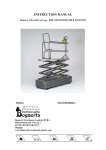
SERVICE MANUAL
SPEEDROLLER
• CE DECLARATIONS
• LOG BOOK
• USER MANUAL
Edition : May 2011
Main components
1
1
2
3
4
5
6
7
8
9
10
11
12
2
3
4
8
5
12
7
9
10
11
6
drive
wind roller with hood (optional)
door panel
aluminium hinge profile
window section
bottom beam
side guide with brush guide
control box
spiral cable
photocell
reflector
CE plug
Contents
Read this first!
Improper use
Warranty terms
Product description
Operation and use
Faults
Maintenance
EU Certificate of Conformity / installation company’s certificate
Delivery checklist
Work performed
Annexes
page
2
2
2
3
4
5
6
7
8
9-12
Exploded drawing / parts list
Order specifications
Electrical diagram(s)
Installation guide
SPEEDROLLER
1
•
•
•
•
•
•
•
•
•
•
•
•
•
•
•
•
2
Read this first!
Read through the whole user manual before using the product.
An electrically-driven door may only be used after it has been issued with a
Certificate of Conformity.
This manual describes the use of a door that has been installed and configured by an
authorised dealer or a suitably qualified engineer.
It is intended for the day-to-day user of the door and must be kept in the immediate
vicinity of the door.
Instruct users how to operate the door.
Do not allow third parties (e.g. visitors) to operate the door.
This product has been designed and manufactured in accordance with the ISO 9001
quality system.
The manufacturer accepts no liability for damage and/or injury caused by failing to
follow the instructions in this manual.
Have the door repaired, maintained and removed by qualified engineers only.
The type plate contains information you will need when you contact your dealer (it
can be found on one of the side guides and on the control box).
The product may only be modified or added to by the supplier.
Warranty conditions
Metaalunie terms and conditions
General terms and conditions of delivery and payment issued by Metaalunie (the Dutch
organisation for small and medium-sized enterprises in the metal industry), referred to as
METAALUNIE TERMS AND CONDITIONS, formerly SMECOMA TERMS AND CONDITIONS, filed with the Registry of the Court of Rotterdam on 1 January 2001.
Issued by Metaalunie
Postbus 2600
3430 GA Nieuwegein
Improper use!
Never place objects against the door panel, against the roller or in the guides.
Never attach any components to the door panel which could increase its weight.
Never use the door as a hoist.
Never climb on the door panel.
Never open and close the door using any other switches than those fitted for that purpose.
Gebruikshandleiding / User manual / Gebrauchsanweisung
Product description
The Novoferm Speedroller is an electrically driven fast action roller door
for use in industrial and commercial buildings. It can be used for energy
saving, draught exclusion and climate control.
Specification, construction
The Novoferm Speedroller is a door without balance springs, consisting of a door panel
that is rolled up by an electrically driven roller above the opening. The door panel is
made of horizontal sections composed of reinforced PVC sheet, linked together by
means of aluminium reinforcement profiles. The door panel is fitted with a transparent
PVC vision section at a height of between approx. 1200 and 2200 mm. The closing edge
of the door panel consists of an aluminium beam with a rubber seal. U-shaped channels
with brush draught seals guide the door panel at the sides. The side guides and the
bearing plates form a unit on which the roller and the drive are mounted.
Materials
The side guides are made of set Sendzimir galvanised steel channels fitted with brush
draught seals that can be removed for installation and maintenance. The horizontal roller
is made of steel. The bottom beam is made of aluminium. The door panel is made of 1.2
mm thick, polyester-reinforced PVC. It is available in blue, orange, yellow or black and is
fitted as standard with a vision section.
Drive
The drive unit consists of an electric motor/gearbox unit and a built-in anti-roll-off device.
The roller is driven directly.
Controls
The control system incorporates a variety of functions such as:
• controllable open position duration (dead man mode)
• service and operating mode
• LED indicator for monitoring the various functions
• choice of permanently open or permanently closed.
SPEEDROLLER
Operation
The control box has two push buttons (open/close) as standard and an emergency stop
switch. The power can be switched off completely by disconnecting the CE plug. Various
actuators can be used: pull switch, key switch, push button, photocell, radar, induction
loop detection or remote control with a transmitter and a receiver. Other types of actuator
on request.
•
•
•
•
•
•
•
•
•
•
•
•
•
•
•
Safety devices
in the event of a power failure the door can be cranked open manually with the crank
supplied.
the bottom beam is fitted with a self-testing safety edge which stops the or immediately causes it to re-open if an obstacle is encountered during closure. This safety
device is moisture-proof.
the side guide channels are fitted as standard with a safety photocell and a reflector
(250 mm from the floor). The door will not close if the beam is broken.
the drive is fitted as standard with an anti-roll-off device.
Fittings/Options/Accessories
door panel 3 mm thick, transparent, blue or orange
plastic rain hood over drive/roller or both
side guide channels and hood painted in choice of RAL colour
aluminium ‘Break Away’ end units in bottom beam (crash resistant)
other electrical supply specifications besides 3N~400V/50Hz/16A
electrical components IP65
frequency inverter control:
opening speed ........................................................................................approx. 1.5 m/s
closing speed........................................................................................approx. 0.75 m/s
actuation using push buttons, pull switches, photocells, radar, induction loop or remote control
half-height stop (for pedestrian access)
interlock switching in combination with another door
traffic light switching (red/green or red and green)
3
•
•
Mounting structure requirements and connection
the power supply must be present within 500 mm of the control box
required installation space as indicated in the installation guide.
Technical specifications
Dimensions
•
•
•
•
•
•
•
•
maximum width.................................................................................................4000 mm
maximum height ...............................................................................................5000 mm
max. wind resistance.......................................................................................5 Beaufort
space required, non-drive side (roller height).....................................................160 mm
space required, drive side ..................................................................................300 mm
space required for installation, drive side ...................................................min. 550 mm
space required, side guide channels ..................................................................110 mm
headroom............................................................................................................575 mm
•
•
•
mains voltage...................................................................................3N~400V/50Hz/16A
degree of protection .................................................................................................IP54
power consumption.........................................................................................max. 2 kW
•
opening and closing speed ........................................................................approx. 1 m/s
Technical specifications of electric motor
Performance
Operating and using the door
Push buttons [i] and [m] on the door of the control box
Push button [i] has two different functions:
timer function
If push button [i] is pressed briefly (less than 1.5 seconds), the door opens and closes
automatically after the set open position delay.
Summer setting
When push button [i] is pressed, the door remains open. The door can be closed by
pressing push button [m].
Reset after safety edge protection actuated
After safety edge protection is actuated, reset by pressing push button [m].
STOP button
Use the STOP button to stop the door in any position. An external UP/STOP/DOWN
push button box can be connected to the control box (optional).
Operating the timer
The door opens when the timer input is activated. A timer starts running as soon as the
door is fully open. The door closes automatically at the end of the set time. The open
position delay is set by means of a potentiometer on the PCB. The timer can be operated
with the following controls: push buttons, pull switches, photocells, radar, radio receiver
with remote control, induction loop detector.
Setting the timer
The time is set with potentiometer P2 (on the control board in the control box). Turn it
clockwise to shorten the open position delay and anti-clockwise to increase it.
4
Gebruikshandleiding / User manual / Gebrauchsanweisung
Door open/door closed control
When the door open/door closed input is activated with the door closed, the door opens.
When the door open/door closed input is activated with the door open, the door closes.
The door-open/door-closed feature can be operated with the following controls: push buttons, pull switches, radio receiver with remote control
Emergency operation in case of a power failure
Make sure you are standing on a sufficiently firm surface next to
the drive.
Take the drive crank and insert it into the drive from underneath. Release the motor
brake (depress the handle at the top of the drive) and crank the door open or closed.
Faults
Faults in standard version
Faults you can fix yourself: standard door version:
The door panel has come out of the guides
• Disconnect the power plug
• Stop the door and rehang the curtain and bottom beam in the guide channel (lift on
one side and rehang). Then open and close the door in a controlled manner (1) by
about 0.5 m at a time.
(1) To do this, press the ‘Up’ or ‘Down’ buttons and the ‘Stop’ button alternately.
The door is completely unresponsive
• Check that it is connected to the mains power
Faults in the timer control box
The door does not respond to connected controls
• Is the power on? (Yellow LED on the box is on)
The door no longer closes
• Check the power supply and the safety photocell setting. The door will not close
when the red LED on the box is on (see also 7.2).
Faults you CANNOT fix yourself:
Have the following information to hand before you contact your maintenance company:
• the serial number (s/n) located on the type plate (you will find this on one of the side
guides or on the control box (if applicable).
SPEEDROLLER
5
Maintenance
•
•
•
•
•
•
•
•
•
•
6
General
Lubrication points
all rotation points are self-lubricating so they are maintenance-free.
in extreme conditions (aggressive environment), we recommend lubricating all rotation points once every six months (or as necessary).
Daily
remove dirt and obstacles that may impede the door’s operation.
Weekly
Check the drive for leaks
Check the door for damage
Check that the door is operating properly
Monthly
Check the operation of the motor brake (this must ‘click’ audibly when the door is
opened and closed)
Annually
The operation of the door and its structural condition must be checked once per year
by a qualified engineer. A maintenance contract can be taken out for this purpose.
Cleaning the door panel
The door panel is made of PVC. Do not use any corrosive substances; only use
water, neutral soap or a special door panel cleaner.
NB!
All other forms of maintenance must be carried out by a suitably qualified engineer.
Gebruikshandleiding / User manual / Gebrauchsanweisung
EU Declaration of Conformity to EN 13241-1
In accordance with EN 13241-1 Industrial, commercial and garage doors and gates Product Standard Annex 2A
Novoferm Nederland BV
Industrieweg 9
4181 CA Waardenburg
The Netherlands
Hereby declares that the Novoferm SPEEDROLLER series fast action roller doors
• Satisfy all the relevant requirements of the EC Construction Products Directive
(89/106/EEC) and, in combination with the factory-specified GFA drive,
• Satisfy all relevant requirements of:
• EC Construction Products Directive (89/106/EEC)
• EC Machinery Directive (98/37/EEC)
• Low Voltage Electrical Equipment Directive (73/23/EEC)
• EMC Directive (89/336/EEC)
The following harmonised standard has been applied:
• EN 13241-1 Industrial, commercial and garage doors and gates - Product Standard
• Conformity has been verified by the following notified body:
RWTÜV Systems GmbH
Notified Body 0044
Langemarckstrasse 20
D 45141 Essen
Waardenburg, January 2011
Signature:
R. Schackmann
Managing Director, Novoferm Nederland BV
SPEEDROLLER
Installation company’s declaration
We declare that we have complied with the manufacturer’s instructions.
Company stamp
Installation company
:
Postcode/Place
:
Street
Phone/fax
Delivery
:
:
Place
:
Date
:
Location
Name of engineer
Signature of engineer
:
:
:
7
Bottom beam
Delivery checklist
Condition of bottom beam channel......................
Location of the door
Guides .................................................................
Guide
Draught seal ........................................................
Operational on
Drive
Attachment of bearing consoles ..........................
Push buttons on box............................................
Condition of door panel .......................................
Attachment to bottom beam ................................
OK/faulty
Controls
Push button* ........................................................
Attachment of tension belts .................................
OK/faulty
OK/faulty
Return pulley for tension belt...............................
Tension belts .......................................................
Tension belt flange ..............................................
Rain cover*
Attachment...........................................................
Maintenance sticker.............................................
Type plate............................................................
Safety devices
Safety edge protection.........................................
OK/faulty
OK/faulty
OK/faulty
Safety photocell ...................................................
* if applicable
Photocell + reflector * ..........................................
Radar * ................................................................
Induction loop *....................................................
Condition of door panel hinges............................
Hand-held transmitter *........................................
8
Tensioning and balancing system *
OK/faulty
Pull switch* ..........................................................
Welds in door panel.............................................
Section clamps ....................................................
OK/faulty
Stop switch ..........................................................
General cabling ...................................................
Door panel earthling ............................................
Various
Motor brake .........................................................
Control box
Explosion-safe*
Seal tightness ......................................................
Leaks ...................................................................
End terminals (settings).......................................
Attachment to roller .............................................
OK/faulty
Motor attachment.................................................
Checked by
Door panel
OK/faulty
Column attachment .............................................
Attachment of roller caps.....................................
Key switch *.........................................................
power conductor, intermediate hinge ..................
Floor rubber .........................................................
Break away * .......................................................
Installation/maintenance checklist
OK/faulty
Receiver * ............................................................
Gebruikshandleiding / User manual / Gebrauchsanweisung
Work performed
Date
work
SPEEDROLLER
performed by
Work performed
Date
work
performed by
9
Work performed
Date
10
work
performed by
Work performed
Date
work
performed by
Gebruikshandleiding / User manual / Gebrauchsanweisung
Work performed
Date
work
SPEEDROLLER
performed by
Work performed
Date
work
performed by
11