1
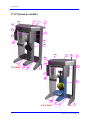
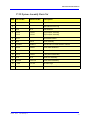
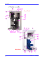
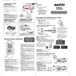
17-19 & 9-17 3D Scanners Service Manual Cone Beam Volumetric Tomography and Panoramic Dental Imaging Systems Service Manual IMPORTANT! . . . X-RAY PROTECTION X-ray equipment may cause injury if used improperly. The instructions contained in this manual must be read and followed when installingthis device. The device provides a high degree of protection from unnecessary X-radiation. However, no practical design can provide complete protection, nor prevent operators from exposing themselves or others to unnecessary radiation. It is important that you become fully acquainted with applicable government radiation protection regulations. Many provisions of these regulations are based on the recommendations of the National Council on Radiation Protection and Measurements. Recommendations for dental X-ray protection are published in NCRP Report Number 35 available from NCRP Publications, 7910 Woodmont Ave., Suite 800, Bethesda, MD 20814, or at www.ncrp.com. Personal radiation monitoring and protective devices are available. You are urged to use them to protect against unnecessary X-radiation exposure. 990410 Rev C 2012 February 15 Table of Contents TABLE OF CONTENTS Chapter 1 - Troubleshooting and Corrective Action Chapter 2 - Calibration Panel Calibration .............................................................................................2-1 Collimators Calibration ...................................................................................2-3 Geometry Calibration (17-19 Models) .............................................................2-4 Geometry Calibration (9-17 Models) ...............................................................2-8 Diagnosing Blurry Image/Failed Reconstruction Due to Bad Geometric Calibration Values ...............................................................2-11 Chapter 3 - Illustrated Parts Breakdown 17-19 System Assemblies .................................................................................3-2 17-19 System Assembly Parts List .......................................................................................... 3-3 17-19 Overhead Assembly ................................................................................3-4 17-19 Overhead Assembly Parts List ...................................................................................... 3-5 17-19 Rotation Drive Assembly .......................................................................3-6 17-19 Rotation Drive Assembly Parts List ............................................................................. 3-7 17-19 X-Ray Source Assembly .........................................................................3-8 17-19 X-Ray Source Assembly Parts List ............................................................................... 3-9 17-19 Flip Receptor Panel Assembly (109-0 or K109-0) ..............................3-10 17-19 Flip Receptor Panel Assembly Parts List (109-0 or K109-0) .................................... 3-11 17-19 Flip Receptor Panel Assembly (133-0 or K133-0) ..............................3-12 17-19 Flip Receptor Panel Assembly Parts List (133-0 or K133-0)) ................................... 3-13 17-19 Chair Assembly ....................................................................................3-14 17-19 Chair Assembly Parts List .......................................................................................... 3-15 17-19 Upper Chair Assembly .........................................................................3-16 17-19 Upper Chair Assembly Parts List ............................................................................... 3-17 9-17 System Assembly ....................................................................................3-18 9-17 System Assembly Parts List .......................................................................................... 3-20 9-17 Overhead Assembly ................................................................................3-21 9-17 Overhead Assembly Parts List ...................................................................................... 3-22 990410 Rev C 2012 February 15 -iii Service Manual 9-17 Rotation Drive Assembly .......................................................................3-23 9-17 Rotation Drive Assembly Parts List ............................................................................. 3-24 9-17 X-Ray Source Assembly .........................................................................3-25 9-17 X-Ray Source Assembly Parts List ............................................................................... 3-26 9-17 Receptor Panel Assembly ......................................................................3-27 9-17 Receptor Panel Assembly Parts List ............................................................................ 3-28 9-17 Chair Assembly ......................................................................................3-29 9-17 Chair Assembly Parts List ............................................................................................ 3-30 9-17 Upper Chair Assembly ...........................................................................3-31 9-17 Upper Chair Assembly Parts List ................................................................................. 3-32 Chapter 4 - IEC IC Command Codes Home Commands .............................................................................................4-1 Movement Commands .....................................................................................4-1 Read Commands ..............................................................................................4-2 X-Ray Commands ............................................................................................4-5 Miscellaneous Commands ...............................................................................4-5 Chapter 5 - VisionQ/Vision Release Notes Chapter 6 - VDE 0751-1 Safety Checks (Germany Only) Safety Checks ...................................................................................................6-1 Visual Inspection .............................................................................................6-2 Safety Tests .......................................................................................................6-2 Test Equipment/Forms Required ........................................................................................... 6-2 Procedure ................................................................................................................................ 6-3 Test Results Form ............................................................................................6-9 Chapter 7 - System Schematics -iv 990410 Rev C 2012 February 15 Chapter 1 Troubleshooting and Corrective Action Error and Probable Cause Corrective Action Chair will not go up or down Loose cable or connection Check all cable connections; check laser function; check laser & up/down together; check chair linear actuator function. Stall detected while overhead rotates Improper gear mesh Check for proper gear mesh between the overhead drive gear and the large overhead gear. No communication between PC & iCAT Ethernet cable or network card loose Ping NIC, Embedded Controller & Panel; check ethernet cable between PC and back of machine; replace ethernet cable. iCAT not powering up Breaker switch turned OFF Check white breaker switch on top rear of iCAT machine - ensure that it is in the "ON" position. X-ray not firing Loose cable or connetion Check all cable connections leading from the x-ray power supply to the x-ray tube head. Fault light is lit - machine not responsive E-stop engaged Check patient e-stop for engagement, turn clockwise to release; check e-stop on/off box for engagement, turn clockwise to release. Ready light is blinking - unable to scan Door interlock switch not engaged Check door interlock switch for proper engagement, if door is open, close door; if handheld "dead-man" switch - engage properly. Warning system light not illuminating during x-ray No power to warning system Check power supply to external warning system (not supplied by ISI); check all wiring to warning system and cable provided. Acquisition PC not booting Bad or unseated RAM Check RAM one by one to ensure PC boot; check power from computer power supply; check motherboard. One side of image is dark after scan Shutter not responding, staying closed Check collimator calibration for any "Slope" values = "0.0"; remove cover over collimators - locate shutter "test" button on Beam Limiter Control PCB, check for loose connections on shutters, replace chip set w/ spare located on shutter assy. 990410 Rev C 2012 February 15 1-1 Service Manual 1-2 990410 Rev C 2012 February 15 Chapter 2 Calibration The Panel, Collimators, and Geometry Calibrations can be conducted by the Owner / Operator of the device or service technicians. It is recommended that the Panel Calibration be performed once a week. Panel Calibration The Panel Calibration is performed for both Portrait and Landscape positions. The entire calibration takes approximately 8 to 10 minutes to complete. The process performs a multi-mode calibration as listed below: 17-19 Models: • Mode 0 (4 x 4) Landscape • Mode 1 (2 x 2) Landscape • Mode 2 (2 x 2) PAN (Landscape) • Mode 3 (4 x 4) Portrait • Mode 4 (2 x 2) Portrait • Mode 5 (1 x 1) PAN (Landscape, not supported) 9-17 Models: 990410 Rev C 2012 February 15 • Mode 0 (4 x 4) Landscape • Mode 1 (2 x 2) Landscape • Mode 2 (1 x 1) PAN (Landscape, not supported) • Mode 3 (2 x 2) PAN (Landscape) • Mode 4 (not supported) • Mode 5 (4 x 4) Portrait • Mode 6 (2 x 2) Portrait 2-1 Service Manual To run the Panel Calibration: 1. Ensure room temperature is in the range of 50 to 95oF (10 to 35oC). 2. From the desktop, double click the Calibration icon. The Calibration screen is displayed. 3. Click the Calibrate button (top) in the Panel field. WARNING The X-ray device may be dangerous to the Patient and operator if you do not observe and follow the operating instructions. Do not operate this system unless you have received training to perform a procedure. A window is displayed “Remove all objects from the field of view and click OK to start X-ray exposure.” 4. Click OK. 5. When prompted, press the Scan button on the Control Box. An audible alarm is sounded and the X-ray ON light is illuminated during radiation exposure. 2-2 990410 Rev C 2012 February 15 Calibration 6. The progress of the scan is displayed on the Progress bar at the bottom of the Acquire window. You will be prompted to press the Scan button several times as the calibration progresses. “Panel Calibration Complete” is displayed when the process is finished. Click OK. Collimators Calibration It is recommended to perform the Collimators Calibration once a week to ensure optimal image quality. This calibration is also necessary if a mechanical adjustment is made to the Beam Limiter or if image quality has degraded. The Collimator Calibration runs in both Portrait and Landscape positions and takes less than 3 minutes to complete. CAUTION The FOV Collimation tool is for German regulatory compliance only. Do NOT use this tool unless you are qualified to do so. A Panel calibration must be performed prior to a Collimators calibration. NOTE: 7. In the Collimations field, ensure Collimator calibration is selected on the Calibrate tab. 8. Click the Calibrate button in the Collimations field. A window is displayed: “Starting Collimator Calibration Remove all objects from the field of view and click OK to start X-ray exposure.” WARNING The X-ray device may be dangerous to the Patient and operator if you do not observe and follow the operating instructions. Do not operate this system unless you have received training to perform a procedure. 990410 Rev C 2012 February 15 2-3 Service Manual 9. Click OK to start the X-ray exposure. 10. On the Control Box, press Scan when prompted. An audible alarm is sounded and the X-ray ON light is illuminated during radiation exposure. 11. The scan starts in the Landscape and continues into the Portrait mode, displaying three screen shots in both modes. 12. Click OK when calibration completes (less than 3 minutes) Geometry Calibration (17-19 Models) It is recommended to perform the Geometry Calibration once a year to ensure optimal image quality or if the image quality is degraded. The Panel Calibration must be performed prior to this. The Geometry Calibration runs in both Portrait and Landscape positions and takes about 12 to 15 minutes to complete. Perform Geometry Calibration: 13. Mount the Phantom Platform and center the BB Phantom on the platform using the alignment holes on the bottom of phantom. (shown below). 2-4 990410 Rev C 2012 February 15 Calibration 14. Ensure that the BB Phantom is level. Use shims or pieces of paper under the phantom to level it if necessary. 15. Align the BB Phantom crosshair slits with the laser cross beams. For an accurate alignment, the laser beams should penetrate though the phantom crosshair slits and appear on the receptor panel. 16. Click the Preview button which is located at the bottom of the Calibration screen. WARNING The X-ray device may be dangerous to the Patient and operator if you do not observe and follow the operating instructions. Do not operate this system unless you have received training to perform a procedure. 17. The ready window is displayed, click OK. 18. On the Control Box, press Scan when prompted. An audible alarm is sounded and the X-ray light illuminates during radiation exposure. 19. The BB Phantom image is displayed (shown below). Back (Volume Center) Front (Volume Center) 20. Ensure that the phantom is centered, level, and all BBs (dots) appear in the Field of View. If required, make adjustments and click Preview again. Repeat as required. 990410 Rev C 2012 February 15 2-5 Service Manual Height adjustments are made by raising or lowering the phantom platform. BBs should not touch the top or bottom lines. To reposition the phantom right or left on the Preview screen, use the Back / Front feature. 21. When the BB Phantom is centered and level, click the Calibrate button on the Geometry panel (bottom). 22. Select both the Landscape and Portrait calibration modes. WARNING The X-ray device may be dangerous to the Patient and operator if you do not observe and follow the operating instructions. Do not operate this system unless you have received training to perform a procedure. 23. Click OK to start the X-ray exposure. 24. On the Control Box, press Scan when prompted. An audible alarm is sounded and the X-ray ON light is illuminated during radiation exposure. 2-6 990410 Rev C 2012 February 15 Calibration 25. The calibration starts with the Landscape Scan. LANDSCAPE SCAN PORTRAIT SCAN Metal Platform Support (below FOV) NOTE: Ensure that the metal platform support is below the Field of View (as shown above.) 26. At the start of the scan, red circles are displayed around each BB. At this point, check data (above green progress bar), to ensure the following is displayed: Beads detected = 24, Beads valid = 24 27. At the prompt, press Scan on the Control Box, to start the Portrait Scan. 28. During the Portrait Scan, ensure the following is displayed: Beads detected = 20, Beads valid = 20 NOTE: Check to ensure that all beads are intact on the BB Phantom, if the calibration did not detect a bead at a certain location. 29. Click OK when the completion window is displayed and restart Vision software. Failure to restart Vision software at this point may result in a system failure. 990410 Rev C 2012 February 15 2-7 Service Manual Geometry Calibration (9-17 Models) It is recommended to perform the Geometry Calibration once a year to ensure optimal image quality or if the image quality is degraded. The Panel Calibration must be performed prior to this. The Geometry Calibration runs in both Portrait and Landscape positions and takes about 12 to 15 minutes to complete. Perform Geometry Calibration: 1. Use the Back / Front feature to ensure the Panel is set to the back. 2. Place BB Phantom on a piece of foam and center the phantom on the platform. 3. Ensure that the BB Phantom is level. Use shims or pieces of paper under the phantom to level it if necessary. 4. Center the BB Phantom (left to right) using the Front Laser. 5. Align the BB Phantom crosshair slits so that the laser beams penetrate through the phantom crosshair slits and appear on the receptor panel. 6. 2-8 Click the Preview button which is located at the bottom of the Calibration screen. 990410 Rev C 2012 February 15 Calibration WARNING The X-ray device may be dangerous to the Patient and operator if you do not observe and follow the operating instructions. Do not operate this system unless you have received training to perform a procedure. 7. The ready window is displayed, click OK. 8. On the Control Box, press Scan when prompted. An audible alarm is sounded and the X-ray light illuminates during radiation exposure. 9. The BB Phantom image is displayed (shown below). Back (Volume Center) Front (Volume Center) 10. Ensure that the phantom is centered, level, and all BBs (dots) appear in the Field of View. If required, make adjustments and click Preview again. Repeat as required. Height adjustments are made by raising or lowering the phantom platform. BBs should not touch the top or bottom FOV. 11. When the BB Phantom is centered and level, click the Calibrate button on the Geometry panel (bottom). 12. Select both the Landscape and Portrait calibrate modes. 990410 Rev C 2012 February 15 2-9 Service Manual WARNING The X-ray device may be dangerous to the Patient and operator if you do not observe and follow the operating instructions. Do not operate this system unless you have received training to perform a procedure. 13. Click OK to start the X-ray exposure. 14. On the Control Box, press Scan when prompted. An audible alarm is sounded and the X-ray ON light is illuminated during radiation exposure. 15. The calibration starts with the Landscape Scan. LANDSCAPE SCAN PORTRAIT SCAN Metal Platform Support (below FOV) NOTE: Ensure that the metal platform support is below the Field of View (as shown above.) 16. At the start of the scan, red circles are displayed around each BB. At this point, check data (above green progress bar), to ensure the following is displayed: Beads detected = 12, Beads valid = 12 17. At the prompt, press Scan on the Control Box, to start the Portrait Scan. 18. During the Portrait Scan, ensure the following is displayed: Beads detected = 8, Beads valid = 8 NOTE: Check to ensure that all beads are intact on the BB Phantom, if the calibration did not detect a bead at a certain location. 2-10 990410 Rev C 2012 February 15 Calibration 19. Click OK when the completion window is displayed and restart Vision software. Failure to restart Vision software at this point may result in a system failure. Diagnosing Blurry Image/Failed Reconstruction Due to Bad Geometric Calibration Values If an image is blurred or doubled, or reconstruction will not complete successfully, perform the following. 1. From the desktop, double click the Calibration icon. The Calibration screen is displayed. 2. Check the following values in the Geometry section. a. Valid values typically fall within the following ranges: • Source-Object distance = 500 (+/- 30) • Source-Detector distance = 700 (+/- 30) • Scan Angle should always be close to 360 b. Bad values will be significantly different from these due to a failed geometric calibration. Re-run Portrait and/or Landscape Geometric Calibration to achieve acceptable values. Example: Good Values 990410 Rev C 2012 February 15 Example: Bad Values 2-11 Service Manual 2-12 990410 Rev C 2012 February 15 Chapter 3 Illustrated Parts Breakdown WARNING High voltage is present in the device. Remove power from device before removing covers or cables. To avoid personal injury from electrical shock, do not operate the system with any covers open or cables removed. This chapter is used to provided replacement part numbers. Ensure power is removed before servicing the device. The following Assemblies are illustrated. Model 17-19 • 17-19 System Assemblies • 17-19 Overhead Assembly • 17-19 Rotation Drive Assembly • 17-19 X-Ray Source Assembly • 17-19 Flip Receptor Panel Assembly (109-0 or K109-0) • 17-19 Flip Receptor Panel Assembly (133-0 or K133-0) • 17-19 Chair Assembly • 17-19 Upper Chair Assembly Model 9-17 990410 Rev C 2012 February 15 • 9-17 System Assembly • 9-17 Overhead Assembly • 9-17 Rotation Drive Assembly • 9-17 X-Ray Source Assembly • 9-17 Receptor Panel Assembly • 9-17 Chair Assembly • 9-17 Upper Chair Assembly 3-1 Service Manual 17-19 System Assemblies 1 14 2 3 13 12 4 11 5 10 6 14 1 2 3 13 12 7 ISI Model 9 4 8 7 11 10 6 7 KaVo Model 3-2 9 8 7 990410 Rev C 2012 February 15 Illustrated Parts Breakdown 17-19 System Assembly Parts List Item 1 ISI Part No. KaVo Part No. Description 102-4 K102-4 Upper Cover 2 BHCS #8-32 x 3/8 Long 3 32-0 32-0 Wall Stabilizer 4 109-0 K109-0 Flip Receptor Assembly 133-0 K133-0 Flip Receptor Assembly 5 101-7 6 20-0 K20-0 Chair Assembly 7 1000031 1000217 IEC #IL8-6B x 3 HX-BC Bottom Chamfer 8 534-0 G534-0 Lower Plate Weldment 9 1000108 1000216 Bottom Chamfer/Leveler 10 106-0 K106-0 X-Ray Source Assembly 11 15-0 15-0 Laser Line Assembly 12 102-3-0 K102-3-0 Lower Cover Assembly 13 1312 K1312 IS i-CAT Logo 14 1302 K1302 Resident Indicator Panel 990410 Rev C 2012 February 15 Rear Scatter Shield 3-3 Service Manual 17-19 Overhead Assembly 31 1 2 3 30 4 5 6 7 29 28 27 26 25 8 24 23 22 21 20 9 19 15 18 15 17 15 16 14 10 13 12 3-4 11 990410 Rev C 2012 February 15 Illustrated Parts Breakdown 17-19 Overhead Assembly Parts List Item ISI Part No, KaVo Part No, Description 1 1000032 1000032 24V Power Supply 2 1000455 1000455 Hook and Loop Fastener 3 #10-32 Nut 4 1000111 1000111 15V Receptor Power Supply 5 1000455 1000455 Hook and Loop Fastener 6 #10-32 Nut 7 1507 1507 Limit Switches (set) 8 9-0 9-0 Spindle Assembly 9 11-0 11-0 Rotation Drive 10 1025-0 1025-0 Network Switch and Power Cable 11 1000455 1000455 Hook and Loop Fastener 12 1701-0 1701-0 Toroid Isolation Transformer 13 14 990410 SHCS 5/16-18 x 1 Long 1015-0-1 K1015-0-1 Power Bracket Assembly 15 1000176 1000176 Buss #HTB-84M 16 1000010 1000010 10A Fuse Digi-Key #F985-ND 17 1000005 1000005 2.5A Fuse Digi-Key #F979-ND 18 1000011 1000011 1/4 A Fuse Digi-Key #F939-ND 19 1255 1255 115VAC Circuit Breaker 1256 1256 230VAC Circuit Breaker 1257 1257 200VAC Circuit Breaker 1258 1258 100VAC Circuit Breaker 20 1310 1310 Fuse Label (not shown) 21 1570 1570 Line Choke 22 102-16 102-16 Stepper Motor Assembly - 17 Frame 23 1557 1557 Ethernet Panel Mount Cable 24 1203 1203 i-CAT System Board 25 1210 1210 i-CAT Computer Board 26 1526 1526 Warning System External Cable Assembly 27 1523 1523 Door Interlock External Cable Assembly 28 1519 1519 Control Box External Cable Assembly 29 1521 1521 Chair External Cable Assembly 30 1000-0 1000-0 X-Ray Power Supply 31 1541 1541 Overhead Fan (pair) Rev C 2012 February 15 3-5 Service Manual 17-19 Rotation Drive Assembly 1 2 3 4 8 15 5 6 9 10 7 11 12 13 14 3-6 990410 Rev C 2012 February 15 Illustrated Parts Breakdown 17-19 Rotation Drive Assembly Parts List Item 990410 ISI/KaVo Part No. Description 1 SHCS #10-24 x 5/8 Long 2 Split Washer #10 3 11-5 Drive Gear 4 11-3 Gear Encoder Disk 5 11-4 Gear Clamp 6 11-2 Rotation Motor Bracket 7 1000027 Al. Round Spacer 8 1205 Gear Encoder 9 Split Washer #6 10 SHCS #6-32 x 1/2 Long 11 11-6 Stepper Motor 12 120110 Thomson Micron #NTR23-025 13 Split Washer #10 14 SHCS #10-24 x 1/2 Long 15 SHCS #10-24 x 3/4 Long Rev C 2012 February 15 3-7 Service Manual 17-19 X-Ray Source Assembly 1 2 6 3 4 8 9 10 5 15 3-8 7 16 17 18 11 12 13 14 19 990410 Rev C 2012 February 15 Illustrated Parts Breakdown 17-19 X-Ray Source Assembly Parts List Item 1 ISI Part No. KaVo Part No. Description 106-7-0 K106-7-0 Rear X-Ray Source Cover 2 BHCS #8-32 x 1/2 Long 3 SHCS 1/4-20 x 1 Long 4 Split Washer 1/4 5 35-0 35-0 Tube Head 6 1539 1539 Cross Laser Assembly 7 106-24 106-24 Cross Laser Mirror 8 BHCS #6-32 x 1/4 Long 9 Split Washer #10 10 SHCS #10-24 x 3/8 Long 11 147-0 147-0 Beam Limiter 12 1305 K1305 Patient Align Panel 13 106-6-0 K106-6-0 Front X-Ray Source Cover Assembly 14 1308-0 1308-0 Beam Limiter Panel 15 1206 1206 Beam Limiter Control PCB 16 1000211 1000211 #6-32 x 1/2 Long Standoff McMaster #91 17 106-8 106-8 Beam Limiter Board Shield 18 Split Washer #6 19 SHCS #6-32 x 1/4 Long 990410 Rev C 2012 February 15 3-9 Service Manual 17-19 Flip Receptor Panel Assembly (109-0 or K109-0) 7 Panel Side 6 2 3 4 5 1 8 11 12 13 14 15 16 10 9 17 18 19 Panel Drive Side 20 21 23 3-10 22 24 990410 Rev C 2012 February 15 Illustrated Parts Breakdown 17-19 Flip Receptor Panel Assembly Parts List (109-0 or K109-0) Item ISI Part No. KaVo Part No. Description 1 109-14 K109-14 Panel Cover 2 800186 800184 Receptor Panel 3 SHCS #8-32 x 3/4 Long 4 Split Washer #8-4 5 1549 1549 Flip Receptor Fan 6 109-11 109-11 Cover Spring 7 BHCS #6-32 x 1/4 8 105-5-0 K105-5-0 Rear Receptor Cover Assembly 9 109-12 109-12 Stop Screw 10 109-0-2 109-0-2 Drive Screw Assembly 11 SHCS M3 x 8mm Long 12 109-2 109-2 Flip Stepper Motor 13 109-31 109-31 Idler 14 109-17 109-17 Cable Shield 15 Split Washer #10 16 SHCS #10-32 x 5/8 Long 17 1000189 1000189 18 19 Spring Extension 109-18 109-18 20 21 109-16 109-16 Belt Key Flat Head Screw #8-32 x 3/8 Long 1550 1550 24 990410 Spring Bushing Shoulder Screw 1/4 Diameter x 1” Long x #10-32 22 23 Belt McMaster #6484K511 Flip Receptor Limit Switch Assembly SHCS #4-40 x 5/8 Long Rev C 2012 February 15 3-11 Service Manual 17-19 Flip Receptor Panel Assembly (133-0 or K133-0) Panel Side 4 2 3 1 5 8 9 10 11 12 13 6 7 14 15 Panel Drive Side 16 18 3-12 20 17 19 990410 Rev C 2012 February 15 Illustrated Parts Breakdown 17-19 Flip Receptor Panel Assembly Parts List (133-0 or K133-0)) Item ISI Part No. KaVo Part No. Description 1 133-14 K133-14 Panel Cover, Varian 2520D 2 800186 800186 Receptor Panel 3 133-2 133-2 Mounting Plate, Receptor 2520D 4 Flat Soc. Hd. M5 5 105-5-0 K105-5-0 Rear Receptor Cover Assy. 6 109-12 109-12 Stop Screw 7 109-0-2 109-0-2 Drive Screw Assembly 8 SHCS M3 x 8mm Long 9 109-2 109-2 Flip Stepper Motor 10 109-31 109-31 Idler 11 109-17 109-17 Cable Shield 12 Split Washer #10 13 SHCS #10-32 x 5/8 Long 14 1000189 1000189 Belt McMaster #6484K511 15 1585 1585 Receptor Fan Assembly 16 109-16 109-16 Belt Key 17 18 Flat Head Screw #8-32 x 3/8 Long 1550 1550 Flip Receptor Limit Switch Assembly 19 SHCS #4-40 x 5/8 Long 20 SHCS #10-32 x 3 1/2 Long 990410 Rev C 2012 February 15 3-13 Service Manual 17-19 Chair Assembly 1 See Upper Chair Assembly 2 3 4 5 35 34 29 30 31 32 9 33 28 10 7 8 6 12 11 13 14 13 22 15 20 23 24 25 16 17 21 19 18 26 27 3-14 990410 Rev C 2012 February 15 Illustrated Parts Breakdown 17-19 Chair Assembly Parts List Item ISI Part No. KaVo Part No. Description 1 1020-0 1020-0 Chair Receptacle Plate Assembly 2 1204 1204 Patient Alignment Board 3 1516 1516 Patient E-Stop External Cable 4 5 Wheel Chair External Cable (removed in later machines) 1522 1522 Chair Junction Cable 6 SHCS 1/4-20 x 5/8 Long 7 1/4 Split Washer 8 505-5 505-5 Rail 9 25-2 K25-2 Back Plate 10 SHCS #6-32 x 1 Long 11 #6 Split Washer 12 Wheel Chair Switch (removed in later machines) 13 1000029 1000029 McMASTER # 97245A688 14 1000028 1000028 MAGNETIC #ECO50-025MM1B0-000 15 23-1 23-1 Wheel 16 23-2 23-2 Wheel Axle 17 SHCS 1/4-20 x 1/2 Long 18 1/4 Split Washer 19 508-0 508-0 Actuator Plate 20 23-3 23-3 Receptacle Flange 21 21-0 G21-0 Seat Assembly 22 23 24 25 1309-3 1.009.2374 21-2 1000457 1309-3 1.009.4972 Chair Installation Label Seat Pad, Bottom 21-2 Seat Frame 1000457 Plastic Spacers 26 M6 Split Washer 27 SHCS M6 x 45mm Long PHP ZN 28 1.009.2375 1.009.4974 Seat Pad, Back 29 23-6 23-6 Back Rest Adapter 30 1/4 Split Washer 31 SHCS M6 x 20mm Long 32 23-5 23-5 33 Seat Back Support SHCS 1/.4-20 x 1/2 Long 34 1309-2 1309-2 Chair Warning Label 2 35 1309-1 1309-1 Chair Warning Label 1 990410 Rev C 2012 February 15 3-15 Service Manual 17-19 Upper Chair Assembly 1 2 3 4 51 5 6 7 8 50 49 9 48 47 10 46 45 11 43 44 42 12 41 40 13 39 38 16 14 17 15 18 37 25 24 26 19 27 20 23 21 22 28 29 36 35 33 3-16 30 34 31 32 990410 Rev C 2012 February 15 Illustrated Parts Breakdown 17-19 Upper Chair Assembly Parts List Item 1 2 3 4 5 6 7 8 9 10 11 12 13 14 15 16 17 18 19 20 21 22 23 24 25 26 27 28 29 30 31 32 33 34 35 36 37 38 39 40 41 42 43 44 45 46 47 48 49 50 51 990410 Rev C ISI/KaVo Part No. Description 22-4 22-2 Clamp Knob Support Plate Nylon Flat Washer 5/16 ID - 3/4 OD Clamp Plate SS 5/16-18 x 1.25 Long SHCS 1/4 - 20 x 5/8 Long Flat Washer 1/4 Slider Block SHCS #8-32 x 1/2 Long Roller Plate Flat Head 1/4-20 x 1/2 Long Left Cap Plate Right Cap Plate Split Washer 1/4 SHCS 1/4-20 x 5/8 Long Dual-Vee #W1 Split Washer #10 SHCS #10-32 x 5/8 Long SHCS 1/4-20 x 1 1/4 Long Split Washer 1/4 Flat Washer 1/4 Hinge Bar Bunting #BM4071 Tee Nut Magnet Plate SHCS #10-24 x 1/4 Long Gate Label Upper Guide BHCS #6-32 x 1/4 Long Lower Guide SHCS #6-32 x 1/2 Long 3/8 Spring Plunger McMaster Carr #8499A85 SHCS 1/4-20 x 5/8 Long Slide Block Dowel Pin 1/4 x 1 Long Gate Gate Pivot Pin Thumb Screw Clamp Button Chin Rest Guide Shoulder Screw 1/8 Diameter x 5/16 Long x #4-40 Century Spring #70464 Bite Tip Clamp Button Glide SHCS #10-32 x 3/4 Long Clamp Handle Bronze Bushing .375 ID x .625 OD x .50 Long Clamp Washer Lock Shaft J.W. Winko #6TCC3/E Arm 22-3 22-1 22-10 22-5 22-6 240360 K24-1 1000045 24-4 24-3 1314 26-11 K26-10 1000181 26-9 K24-2 24-6 26-4 26-3 26-1 310242 26-2 22-8 K22-11 22-12 22-9 1000047 K22-7 2012 February 15 3-17 Service Manual 9-17 System Assembly 13 1 2 3 Gendex Model 12 4 11 5 10 6 3 7 9 8 7 1 13 2 12 4 5 11 6 10 KaVo Model 7 3-18 8 9 990410 Rev C 7 2012 February 15 Illustrated Parts Breakdown 3 1 13 2 12 4 5 11 10 6 ISI Model 7 990410 Rev C 2012 February 15 8 9 7 3-19 Service Manual 9-17 System Assembly Parts List Item Gendex Part No. KaVo Part No. ISI Part No. Description 1 G150-4-0 G150-4-0 G150-4-0 Upper Cover 2 3-20 BHCS #8-32 x 3/8 Long 3 32-0 32-0 32-0 Wall Stabilizer (not shown) 4 G138-0 K138-0 1.008.8080 Flip Receptor Assembly 5 G101-7 K101-7 G101-7 Rear Scatter Shield 6 20-0 K20-0 20-0 Chair Assembly 7 1000031 1000031 1000031 IEC #IL8-6B x 3 HX-BC Bottom Chamfer 8 G534-0 G534-0 G534-0 Lower Plate Weldment 9 1000108 1000108 1000108 IEC #IL8-6B x 2 HX-BC Bottom Chamfer 10 G140-0 K140-0 1.008.8082 X-Ray Source Assembly 11 15-0 15-0 15-0 Laser Line Assembly 12 G150-3 K150-3 1.008.8091 Lower Cover 13 1302 K1302 1302 Resident Indicator Panel 990410 Rev C 2012 February 15 Illustrated Parts Breakdown 9-17 Overhead Assembly 31 1 2 3 30 4 5 6 7 29 28 27 26 25 8 24 23 22 21 20 9 19 15 18 15 17 15 16 14 10 13 11 12 990410 Rev C 2012 February 15 3-21 Service Manual 9-17 Overhead Assembly Parts List Item Gendex/ISI/KaVo Part No. Description 1 1000032 24V Power Supply 2 1000455 Hook and Loop Fastener 3 #10-32 Nut 4 1000236 Integrated Power Design (Receptor Power Supply) 5 1000455 Hook and Loop Fastener 6 #10-32 Nut 7 1507 Limit Switches (set) 8 9-0 Spindle Assembly 9 11-0 Rotation Drive 10 1025-0 Network Switch and Power Cable 11 1000455 Hook and Loop Fastener 12 1701-0 Toroid Isolation Transformer 13 14 3-22 SHCS 5/16-18 x 1 Long K1015-0 Power Bracket Assembly 15 1000176 Buss #HTB-84M 16 1000010 10A Fuse Digi-Key #F985-ND 17 1000005 2.5A Fuse Digi-Key #F979-ND 18 1000011 1/4 A Fuse Digi-Key #F939-ND 19 1255 115VAC Circuit Breaker 1256 230VAC Circuit Breaker 1257 200VAC Circuit Breaker 1258 100VAC Circuit Breaker 20 1310 Fuse Label (not shown) 21 1570 Line Choke 22 102-16 Stepper Motor Assembly - 17 Frame 23 1557 Ethernet Panel Mount Cable 24 1203 i-CAT System Board 25 1210 i-CAT Computer Board (Embedded Board) 26 1526 Warning System External Cable Assembly 27 1523 Door Interlock External Cable Assembly 28 1519 Control Box External Cable Assembly 29 1521 Chair External Cable Assembly 30 1000-0 X-Ray Power Supply 31 1541 Overhead Fan (pair) 990410 Rev C 2012 February 15 Illustrated Parts Breakdown 9-17 Rotation Drive Assembly 1 2 3 4 8 15 5 6 9 10 7 11 12 13 14 990410 Rev C 2012 February 15 3-23 Service Manual 9-17 Rotation Drive Assembly Parts List Item 3-24 Gendex/ISI/ KaVo Part No. Description 1 SHCS #10-24 x 5/8 Long 2 Split Washer #10 3 11-5 Drive Gear 4 11-3 Gear Encoder Disk 5 11-4 Gear Clamp 6 11-2 Rotation Motor Bracket 7 1000027 Al. Round Spacer 8 1205 Gear Encoder 9 Split Washer #6 10 SHCS #6-32 x 1/2 Long 11 11-6 Stepper Motor 12 120110 Thomson Micron #NTR23-025 13 Split Washer #10 14 SHCS #10-24 x 1/2 Long 15 SHCS #10-24 x 3/4 Long 990410 Rev C 2012 February 15 Illustrated Parts Breakdown 9-17 X-Ray Source Assembly 1 2 6 3 4 Rev C 8 9 10 5 15 990410 7 2012 February 15 16 17 18 11 12 13 14 19 3-25 Service Manual 9-17 X-Ray Source Assembly Parts List Item 1 Gendex Part No. KaVo Part No. ISI Part No. Description G140-7 K140-7 1.008.8090 Rear X-Ray Source Cover 2 BHCS #8-32 x 1/2 Long 3 SHCS 1/4-20 X 1 Long 4 Split Washer 1/4 5 35-0 35-0 35-0 Tube Head 6 16-0 16-0 16-0 Cross Laser Assembly 7 106-24 106-24 106-24 Cross Laser Mirror 8 BHCS #6-32 x 1/4 Long 9 Split Washer #10 10 SHCS #10-24 x 3/8 Long 11 147-0 147-0 147-0 Beam Limiter Asst 12 G1305 K1305 1305 Patient Alignment Panel 13 G140-2 K140-2-0 G140-2 Front X-Ray Source Cover 14 1308-0 1308-0 1308-0 Beam Limiter Panel 15 1206 1206 1206 Beam Limiter Control PCB 16 1000211 1000211 1000211 #6-32 x 1/2 Long Standoff McMaster #91 17 106-8 106-8 106-8 Beam Limiter Board Shield 18 Split Washer #6 19 SHCS #6-32 x 1/4 Long 3-26 990410 Rev C 2012 February 15 Illustrated Parts Breakdown 9-17 Receptor Panel Assembly Drive Side 1 2 20 3 21 4 22 5 6 7 8 9 10 11 12 18 13 19 17 16 15 14 Receptor Side 23 24 25 26 990410 Rev C 2012 February 15 27 28 29 3-27 Service Manual 9-17 Receptor Panel Assembly Parts List Item Gendex Part No. KaVo Part No. ISI Part No. Description 1 G138-20 K138-20 1.008.8081 Rear Cover 2 3 BHCS #8-32 x 1/2 1000237 1000237 1000237 Camera Card Pleora #PT1000-Cl4-E 4 SHCS #6-32 x 3/8 Long 5 Split Washer #6 6 Flat Washer #6 7 138-3 138-3 138-3 Shift Motor 8 SHCS M3 x 8mm Long 9 Split Washer M3 10 Nut #8-32 (shift motor) 11 1000259 1000259 1000259 Spring McMaster #94135K13 12 138-11 138-11 138-11 Plunger 13 310243 310243 310243 Century Spring #70602 14 SHCS #10-32 x 5/8 Long 15 Split Washer #10 16 138-10 138-10 138-10 Plunger Block 17 1000188 1000188 1000188 McMaster # 8511A24 18 Shoulder Screw 1/4 Diameter x 1 1/4 Long x #10-32 19 1000257 1000257 1000257 Century Spring #71126 20 1550 1550 1550 Flip Receptor Limit Switch 21 SHCS #4-40 x 3/4 Long 22 Split Washer #4 23 G138-18 G138-18 G138-18 Panel Cover 24 800170 or 800172 800170 or 800172 800172 1313 Receptor 25 SHCS M5 x 10mm 26 Split Washer M5 27 BHCS 3/8-16 x 3/4 28 29 3-28 240361 240361 240361 Dual Vee #W2 Shim Washer 3/8 ID x .02 Thick 990410 Rev C 2012 February 15 Illustrated Parts Breakdown 9-17 Chair Assembly 1 See Upper Chair Assembly 2 3 4 5 34 29 30 31 32 9 33 28 10 7 8 11 6 12 13 14 13 22 15 20 23 24 25 16 17 21 19 18 26 27 990410 Rev C 2012 February 15 3-29 Service Manual 9-17 Chair Assembly Parts List Item Gendex Part No. KaVo Part No. ISI Part No. Description 1 1020-0 1020-0 1020-0 Chair Receptacle Plate Assembly 2 1204 1204 1204 Patient Alignment Board 3 1516 1516 1516 Patient E-Stop External Cable 4 5 Wheel Chair External Cable (removed from later machines) 1522 1522 1522 6 SHCS 1/4-20 x 5/8 Long 7 1/4 Split Washer 8 505-5 505-5 505-5 Rail 9 K25-2 K25-2 K25-2 Back Plate 10 SHCS #6-32 x 1 Long 11 #6 Split Washer 12 Wheel Chair Switch (removed from later machines) 13 1000029 1000029 1000029 McMASTER # 97245A688 14 1000028 1000028 1000028 MAGNETIC #ECO50-025MM1B0-000 15 23-1 23-1 23-1 Wheel 16 23-2 23-2 23-2 Wheel Axle 17 SHCS 1/4-20 x 1/2 Long 18 1/4 Split Washer 19 508-0 508-0 508-0 Actuator Plate 20 23-3 23-3 23-3 Receptacle Flange 21 21-0 G21-0 21-0 Seat Assembly 22 1309-3 1309-3 1309-3 23 1.009.2374 1.009.4972 1.009.2374 24 25 21-2 1000457 21-2 1000457 Chair Installation Label Seat Pad, Bottom 21-2 Seat Frame 1000457 Plastic Spacer 26 M6 Split Washer 27 M6 x 45mm Long PHP Zn 28 1.009.2375 1.009.4974 1.009.2375 Seat Pad, Back 29 23-6 23-6 23-6 Back Rest Adapter 30 1/4 Split Washer 31 SHCS M6 x 20mm Long 32 23-5 23-5 23-5 33 34 3-30 Chair Junction Cable Seat Back Support SHCS 1/.4-20 x 1/2 Long 1309-2 1309-2 1309-2 Chair Warning Label 2 990410 Rev C 2012 February 15 Illustrated Parts Breakdown 9-17 Upper Chair Assembly 1 2 3 4 51 5 6 7 8 50 49 9 48 47 10 46 45 11 43 44 42 12 41 40 13 39 38 16 14 17 15 18 37 25 24 26 19 27 20 23 21 22 28 29 36 35 33 990410 Rev C 30 34 2012 February 15 31 32 3-31 Service Manual 9-17 Upper Chair Assembly Parts List Item 1 2 3 4 5 6 7 8 9 10 11 12 13 14 15 16 17 18 19 20 21 22 23 24 25 26 27 28 29 30 31 32 33 34 35 36 37 38 39 40 41 42 43 44 45 46 47 48 49 50 51 3-32 Gendex/ISI/KaVo Part No. Description 22-4 22-2 Clamp Knob Support Plate Nylon Flat Washer 5/16 ID - 3/4 OD Clamp Plate SS 5/16-18 x 1.25 Long SHCS 1/4 - 20 x 5/8 Long Flat Washer 1/4 Slider Block SHCS #8-32 x 1/2 Long Roller Plate Flat Head 1/4-20 x 1/2 Long Left Cap Plate Right Cap Plate Split Washer 1/4 SHCS 1/4-20 x 5/8 Long Dual-Vee #W1 Split Washer #10 SHCS #10-32 x 5/8 Long SHCS 1/4-20 x 1 1/4 Long Split Washer 1/4 Flat Washer 1/4 Hinge Bar Bunting #BM4071 Tee Nut Magnet Plate SHCS #10-24 x 1/4 Long Gate Label Upper Guide BHCS #6-32 x 1/4 Long Lower Guide SHCS #6-32 x 1/2 Long 3/8 Spring Plunger McMaster Carr #8499A85 SHCS 1/4-20 x 5/8 Long Slide Block Dowel Pin 1/4 x 1 Long Gate Gate Pivot Pin Thumb Screw Clamp Button Chin Rest Guide Shoulder Screw 1/8 Diameter x 5/16 Long x #4-40 Century Spring #70464 Bite Tip Clamp Button Glide SHCS #10-32 x 3/4 Long Clamp Handle Bronze Bushing .375 ID x .625 OD x .50 Long Clamp Washer Lock Shaft J.W. Winko #6TCC3/E Arm 22-3 22-1 22-10 22-5 22-6 240360 K24-1 1000045 24-4 24-3 1314 26-11 26-10 1000181 K26-9 K24-2 24-6 26-4 26-3 26-1 310242 26-2 22-8 K22-11 22-12 22-9 1000047 K22-7 990410 Rev C 2012 February 15 Chapter 4 IEC IC Command Codes Home Commands HB Home Beam Limiter (HB = 0, 0, 0, 0 All four shutters completely open) HFR Homes gantry and sets position to 100000 HP Homes gantry and sets position to 1500 HSR Quick home check if the machine is already homed Movement Commands MB Move Beam Limiter right left top bottom Enter command as MB X X X X where X is: (right left and bottom shutters range: 0 – 2600) (top shutter range: 0 – 3300) Example: MB 700 700 3000 1500 MP Move Platform [target] [speed] Enter command as MP X X where X is: (target range: 1500 – 100000, speed range: 1000 – 54000) Example: MP 1500 1500 MPM Target Speed. Enter command as MPM X X where X is: Target or Position: between 0 - 90 mm (home position is zero - absolute) Speed: between 1000-54000 Example: MPM 20 1500 MPP Position type, moves receptor panel’s position. Enter command as MPP X X where X is: Position: 0 or 1 (Landscape or Portrait/Halfbeam) Type: 0 or 1 (Platinum or Nano) Example: MPP 1 0 990410 Rev C 2012 February 15 4-1 Service Manual MR Target Speed. Enter command as MR X X where X is: Target: between 35000 - 733333 Speed: between 1000 - 65000 Example: MR 35000 1000 MRD Target Speed. Enter command as MRD X X where X is: Target: between -40 - 430 degrees (home position is equal to zero degrees - absolute) Type: between 1000 - 65000 Example: MRD 180 1000 Read Commands RB Read beam position returns right left top bottom shutter positions RD Read Door Status: 1 -Open and 0 -Closed RE Read Exception Register Exceptions 1 Emergency Stop activated 2 Stall Detected 4 X-ray Tube Short 8 X-ray Watchdog Timeout 16 Linux Watchdog Error 32 X-ray Fault from X-ray Controller 64 Platform needs to be Homed 128 Rotation needs to be Homed 256 Beam Limiter Not Initialized 512 Machine is Turned Off 1024 Door Interlock was Opened During an X-ray Exposure 2048 Ethernet Cable Communication Failed During an X-ray Exposure 4096 The Panel Position error - both limit switches are reading high or low 4-2 990410 Rev C 2012 February 15 IEC IC Command Codes RI Read Input Register to the RI Read Input Command - returns the 21 bit input register with the following definition: 1 Emergency Stop 2 Machine On Switch 4 Machine Off Switch 8 Scan Enable Button Status 16 Error from X-ray Controller 32 Encoder Direction 64 Rotation Optical Switch Status 128 Rotation Limit Switch 256 Rotation Start of Travel Status 512 Rotation End of Travel Status 1024 Platform Start of Travel Status 2048 Platform End of Travel Status 4096 Door Signal 8192 Panel Horizontal (Landscape) 16384 Panel Vertical (Portrait) 32768 Machine Power Status 65536 Right Shutter Limit Switch 131072 Left Shutter Limit Switch 262144 Top Shutter Limit Switch 524288 Bottom Shutter Limit Switch 1048576 Moving Signal for Panel Flip Motion 2097152 Moving Signal for Rotation Motion 4194304 Moving Signal for Platform Motion RMS Read usage time of selected item Returns xxxxdxxhxxmxxs 0 Beam Limiter Motors 1 Embedded Board 2 Panel 3 Platform Motor 4 24V Power Supply 5 Rotation Motor 6 X-ray 7 Flipper Motor RP 990410 Rev C 2012 February 15 Read Platform position 4-3 Service Manual 4-4 RPP Read Panel Position 0 Error 1 Landscape mode 2 Portrait mode 3 Error RR Read Rotation position. RX Read X-ray Setup See SX command for argument description. 0 = 120KV Range 1 = 90 KV Range If no parameter is entered, then the command assumes 0. SP Sets platform position - Sets the counts of the platform. Must be less than 65000. SR Sets rotation position - Sets the counts of the rotation. Must be less than 733333. SX Set X-ray kvp, ma, frame rate, xrayon, xrayoff, panel readout, panel_mode Enter command as SX X1 X2 X3 X4 X5 X6 X7 X8 where X is: X1 specifies kV = 80 - 126 in increments of 2 only. X2 specifies mA = 0-2. 0=3mA, 1=5mA, 2=7mA X3 specifies frame rate = in between 50000000 - 833333 => 50 MHz/frame rate (1-60 frames/sec) X4 specifies X-ray on = typically set to 1 and between 0 - (frame rate - 1) X5 specifies X-ray off => greater than X-ray on and less than (frame rate - 1) 5000 =1 msec (set as needed for desired length) X6 specifies Panel Readout = Typically set the same as the X-ray off (except for continuous X-ray mode) in between 0 - (frame rate - 1) X7 specifies Panel Pulse mode (0 or 1) (if not entered, defaults to 0). 0 - 20 microsecond pulse for panel readout and valid frame. 1 - either a 5msec pulse for valid frame or 3msec for panel readout X8 specifies the tube 0 = 120 KV tube, 1 = 90 KV tube Example: SX 120 1 3333333 1 780000 780000 0 If X7 and X8 are not specified, both are assumed to be zero. 990410 Rev C 2012 February 15 IEC IC Command Codes X-Ray Commands XP Frames Maximum limit capped by the 44 second x-ray watchdog Number of frames: 1 - 1024 Ethernet Watchdog 0 = disabled, 1 = enabled (Number of frames*Frame Rate) <44 seconds Miscellaneous Commands GS CS Read System Information Machine Version, Hardware Version, Software Version Beam Limiter Version, Machine Serial Number Cancel Scan. Cancels a scan. CE Clear Exception Register. Clears all exceptions except for error that require initialization. WSB Enable Scan Button. Enables the scan button to initiate a scan. 990410 Rev C 2012 February 15 4-5 Service Manual 4-6 990410 Rev C 2012 February 15 Chapter 5 VisionQ/Vision Release Notes New Features for 1.9.3 Added DAP information to scan parameters dialog, which is displayed prior to the scan. Preview images are automatically saved as part of the patient’s dataset. InVivo application can be launched from Vision without first loading a study. Vision standalone is now supported in Windows 7 Professional or Ultimate (32-bit or 64-bit modes). New Features for 1.9.2 Vision software translated into Turkish, Chinese, and Russian and new 1.9 features available in all supported languages. New Features for 1.9.1 Added study progress indicators to the Patient Study List which show whether a study is acquiring, reconstructing, transferring, or ready for viewing. Added a Quantum IQ tag to studies on the Patient Study List that have the Quantum IQ filter applied. Added a rotation tag to studies on the Patient Study List that have been volume rotated and reimported into the Patient Database. Added feature to import a study into the Patient Database. Added feature to rescan and update the Patient Database. Added feature to designate a "Fast" computer as the master of the Patient Database. Added feature to support DICOM Storage Commitment on a separate connection in RSSM. Moved option to turn on/off DICOM Auto Send to the main Tools Settings menu. 990410 Rev C 2012 February 15 5-1 Service Manual Added feature to export a rotated CT volume in DICOM format, and optionally reimport it into the Patient Database. Added feature to launch Dolphin 3DTM software with the current study. Added Dose Area Product (DAP) support for Sweden and the Netherlands. Added CT custom collimation protocols to systems with Dose Area Product (DAP) enabled. New Features for 1.9.0 TM Added Quantum IQ feature which smoothes out the noise in the soft tissue of CT images while preserving the detail in bone and other hard materials. Added support for SureSmile customers by improving the HU and Spatial resolution of CT images. Added features to support Dose Area Product (DAP) compliance. Added DICOM Little Endian Implicit Transfer Syntax support for sending/receiving reconstructed CT and PAN DICOM files to/from a DICOM PACS server. Added feature to automatically send reconstructed iPAN images to a DICOM PACS server. New Features for 1.8.1 Added support for Cesium detector panel on GXCB-500, and 3D eXam i scanners. Added features to allow compliance testing for DIN-standards for iPan mode in Germany. Added support for multi-byte languages, allowing support for Japanese and Korean language translations of the software. This feature also adds support for patient and referring physician names with multiple representations (single-byte, ideographic, and phonetic representations). Dutch, Polish, and Czech language translations were also added. 5-2 990410 Rev C 2012 February 15 VisionQ/Vision Release Notes ID Resolved Issues in 1.9.3 1430 1431 DAP measurements refined for 6cm protocols on MFOV. 1439 1444 German translations corrected in Setup screen. 1450 Patient study access time upon startup is much improved due to better sorting algorithms. 1452 Erroneous reporting of firmware version verification failures has been corrected. 1453 1454 Patient study visibility corrected for overnight VisionQ application runs. Patient list entries are no longer duplicated when DOB not provided with patient information via PM/Worklist. When attempting to load an invalid dataset, the user is notified and the application exits. HU baseline data for MFOV Cesium panels has been improved. ID 1362 1380 1410 1414 1415 1417 1418 1419 990410 Rev C Resolved Issues in 1.9.2 Numerous Japanese-language errors have been corrected. The Contour line Setup Dialog (Maxilla or Mandible option) will no longer appear multiple times when the automatic arch feature fails for either of the arches. New installs of acquisition software no longer display a warning message regarding modification of iCATSystem.xml file on first run. Database rebuilds initiated during software upgrades will not encounter insufficient-memory errors under normal conditions. Large database may be upgraded without the need to restart the software. Systems employing backup software which sets the Archive attribute on files and folders will no longer interfere with display of new patients and scans. Interrupted scans will no longer result in the possible reconstruction of scan-data from previous scans. This problem could have resulted in corrupted images or images corresponding to different patients. Collimation shutter positions will now be correct when using custom collimation protocols saved as Quick Picks. CT studies containing invalid data will be displayed in the study-list after an upgrade, but attempts to open one of these studies will result in an error message displayed to the user, and the study will not be loaded. 2012 February 15 5-3 Service Manual ID 1425 1426 ID 593 753 1028 1098 1105 1110 1117 1158 1163 1226 1256 1273 1279 1287 1308 1311 5-4 Resolved Issues in 1.9.2 Corrected vertical field-of-view size for 6 cm scan protocols on GXCB500 and 3DeXam i systems, which were resulting in 8 cm previews and raw-data. Retro-reconstruction will no longer result in intermittent failure to display preview images with loss of QF Toggle functionality after loading raw data. Resolved Issues in 1.9.1 Patients with same Patient ID but differing names or birth dates will now be displayed on the Patient List as separate patients, and only the studies corresponding to the selected patient will be shown on the Study List. HU values on Half-Beam and Laterally Collimated scans are now more accurate. JPEG and TIF images for Reconstruct PAN images are now exported to the correct folder. Crashes and other abnormal behavior during update of the Patient List have been corrected. DICOM Storage Commitment now works on a separate connection in RSSM. Factor of 2 error in HU values on Half-Beam and Laterally Collimated scans has been corrected. Crashes when loading DICOM file with empty pixel spacing in tag (0028,0030) has been corrected. The TMJ axial image no longer gets magnified when using "Fit To Window" on reports. High resolution/large volume custom collimation CT scan vertical collimation settings are now limited to prevent out of memory conditions. An issue where blank images are printed to pdf files from reports has been corrected. Exporting of a 0.125mm CT scan as a single uncompressed DICOM file now functions properly. Sure Smile customers are supported in this software release. Retro-reconstruction of landscape scans now lists the proper allowable reconstruction protocols. MFOV Roll-Off correction values are now correct for the HU QA test. Measurements on the Implant Screen no longer shift vertically in Reports for LFOV Portrait (17cm) scans. The blue vertical cross-section lines representing condyle positions on the TMJ screen are now positioned correctly in Reports. 990410 Rev C 2012 February 15 VisionQ/Vision Release Notes ID 1316 1320 1321 1330 1337 1338 1340 1348 1352 1354 1355 1359 1360 1370 1373 1374 1378 1388 1395 1408 990410 Rev C Resolved Issues in 1.9.1 The tick annotation on report images generated from the Axial Image on the Implant screen is now sized to minimize covering of anatomy. The slice location tag in DICOM files for the 0.125 resolution CT scans now contains the correct value. The image matrix size for MFOV 8.5cm custom protocols now matches the corresponding standard protocols. MFOV 14cm diameter custom 6.6cm CT scan reconstructions no longer fail. Sorting by Referring Physician on the DICOM Modality Worklist Screen in RSQM now works properly. The Station Name is now retrieved from a DICOM Modality Worklist SCP. Factory Quick Picks can no longer be deleted on non-English systems. The speed search text box in the Select Patient Dialog is now always positioned within the screen. Proper preview scans are now displayed on the Acquisition/ Reconstruction Screen after initiating a CT retro-reconstruction. Cancelling a Tru-PAN rendering followed by cancelling the Select Panoramic Method Dialog no longer confines the user to the Preview Screen. Exporting data using the single file selection now preserves proper HU values. Datasets retrieved from GE PACS servers that are adding the sequence to private tag (7fe0,0010) can now be read. A crash in RSQM has been fixed by no longer allowing the user to retrieve a study while another study is being retrieved. Image quality for retro-reconstructions has been improved by using the Air Cal value from the original study if it is available, rather than using the current Air Cal value from the scanner. Arches are no longer recomputed when an Implant screen rotation is performed followed by a switch to the Preview Screen. Rotations on the MPR screen are now maintained in workups. A crash during rotation of the panoramic image on the Implant Screen has been fixed. Adding a BMP or JPEG image to a Report no longer causes an application crash. InVivo launching now works on non-English and 64-bit OS systems. Switching between preview screens during an acquisition now behaves properly and no longer causes an application crash. 2012 February 15 5-5 Service Manual ID 113 150 158 177 225 230 239 273 288 293 316 372 380 382 392 5-6 Known Issues On Implant screen, pressing Alt-F4 does not return to Preview Screen as with TMJ, Ceph, MPR screens. Using the right-click shortcut does not show the Workup menu selection after a scan has been taken. Wrong message displays during Geo Cal. Message “Preparing Geocalibrate preview acquisition” should display instead of “Moving panel to Landscape”. In Reports, changing the size of Image (when Clip option is selected) displays the ruler at wrong position. GXCB-500 Only: Collimation Calibration GUI in Calibrate.exe uses Portrait, Landscape terminology. E-stop button needs to be released to stop multiple dialogs from displaying. Workaround: User must obey the message “E-stop is pressed” dialog box and lift the E-Stop button when trying to enter Acquisition screen. Stopping Geo Cal closes Calibration application. Workaround: Restart Calibration application. iPAN slide bar covering only 980 frames from 1276. Sometimes after burning a CD (single-uncompressed format) with a workup saved, when loading the CD, the workup name appears as NO NAME. Performing a second Geo Cal after a successful first test causes problem. Shutter location not calculated correctly for customizations and defaults are not remembered for Landscape and Portrait Geo Cal. Workaround: Restart the Calibration application to resolve problem. Filter Settings “Reset to Default” fails to reset default setting although right-click check indicates default settings. 3DVR crashes when dragging the slider bar in the Range 4 section when using the Identify feature in Ax Views. Level Up option under top menu has been changed. Related to FR0256. Workaround: Use Screen menu option. GXCB-500 Only: When user goes into the estimate nerve canal feature and confirms canal, if user changes the default matrix size from 5x2 to be either 3x1 or 7x3, errors are displayed. Export CD: CD creation fails when selecting Multi-File DICOM. 990410 Rev C 2012 February 15 VisionQ/Vision Release Notes ID 394 396 413 422 481 482 489 491 496 523 527 534 540 543 547 550 553 990410 Rev C Known Issues Export CD: The data size estimate is identical for compressed and uncompressed. The “Total to Write” size is not accurate when the uncompressed option is selected. When removing data outside of scanfield, 5 to 6 mm of data is removed. 3DVR application: Error message displays after a second data set is opened when a Calculate VRT is performed. When opening the Implant view, part of the axial image is outside the edge of the view. Reports: No print preview option. Relates to FR-0541. Reports: Undo option is grayed out. Relates to FR-0546. In Reports, missing landscape template containing Panoramic data only. Related to FR-0388. GXCB-500 Only. In Reports, variables in a template need to be added in separate boxes in order to be updated properly from case to case, when using the same template for different cases. PAN: Method to lock bite stick vertically does not exist. Previewing continuously within the Calibration application causes the image to flicker between last preview and current one. Chair alignment inaccurate in field. Workaround: Align the placement of the chair using the calibration procedure and the Chair Alignment functionality in the Calibration application. GXCB-500 Only: When capturing a PAN scan, if e-stop button is pressed, incorrect dialog is displayed instructing to “Close door to continue scan message”. If Retry is selected on dialog, application stays in a loop. Workaround: User needs to click on Cancel to clear exception and have proper message displayed related to e-stop button pressed. When autodetecting arches, infrequently blue dots appear but not green line. GXCB-500 Only: New scan is not highlighted after a scan has been taken. The previous loaded CT is highlighted. GXCB-500 Only: VisionQ application does not respond if an implant template is loaded using a lower matrix. GXCB-500 Only: High Resolution Half Scans. Acquisition screen displays a black frame when adjusting W/L during the reconstruction process. GXCB-500 Only: Preview Screen. Coronal view changes from RAD to MIP if user enters Ceph Screen, and then returns to Preview screen. 2012 February 15 5-7 Service Manual ID 578 583 593 600 605 606 611 615 618 624 640 651 661 664 668 5-8 Known Issues GXCB-500 Only: Preview Screen. Axial view RAD projection changes to MIP when moving the height of any arch. GXCB-500 Only: Volume center stays in the Back position for CT, instead of the last position it was set to, when going from iPAN to CT mode. Patient List: If data and/or images are moved from one system to another and the patient ID collides with an existing patient, the new data and/or images will be included in the existing patient's Patient List entry. However, the patient information displayed in the Vision window and any reports generated will be correct since that information is taken directly from the DICOM fields in the files, not the Patient List. Finding the newly added patient under these circumstances can be difficult, since it will appear under the original patient's name. GXCB-500 Only: 3D airway image should display the proper cursor to move image. Zoom, W/L and Pan do not apply. MF and BD display previous loaded CT values when a new scan has been taken. Workaround: Change to the desired Display Format prior to performing the Nerve Canal estimation. Report: An empty Report folder gets created in the path where an iPAN jpeg is saved. Recon BACK_PRJ crash when using two monitors on ACQ. Workaround: Do not use a second monitor on the VisionQ system. Reports: Saved report contains stray characters and missing/misaligned text. Vertical lines displayed in cross-section view of Implant screen. Some viewing parameters are not retained when exiting and re-entering sub-screens. TMJ report does not retain sizing when reopened. GXCB-500 Only: After nerve canal detection, when ST < = 1.0mm on, panoramic arch gets out of place when moving the diagonal control to move arch to see the canal. Workaround: Adjust arch in main Preview window. Incorrect display and crash using reports. Workaround: Select 20 or fewer description / options when adding text to a report. Nerve canal error with a missing link. Interpolation / filtering is not applied automatically when using mouse to scroll through slices in MPR screen. 990410 Rev C 2012 February 15 VisionQ/Vision Release Notes ID 682 685 693 700 703 737 753 879 962 967 Known Issues Nerve Canal question screen text appears when any pervious nerve canal has been done on the dataset. Workaround: Select Yes to remove previous nerve canal detection. Control panel X-ray ready light not in sync with popup window “Push scan button”. Workaround: Wait for popup window prior to pressing scan button for X-ray ready light. GXCB-500 Only: Preview image does not refresh after the E-stop / Door software has been activated during a CT scan. Report/volume slice mapping not unambiguously possible, especially left/right determination. Calibration: Chair alignment feature should work with the platform (panel) set only at home position. Workaround: Move the platform (panel) all the way to the back (home) position prior to performing the chair calibration. Reports: Out of Memory exception on JPEG export. Hounsfield values will not be correct for new 17-19 8x8 protocol released in both iCAT and 3DeXam. HU values will be too low (attributable to bilateral truncation effects). Attempting to run Calibration when there is no network connectivity to the scanner, or the device ID is powered-off, will result in an error message displayed to the user that the device is not powered-on. After dismissing this message, the Calibration application appears to have quit, but is actually still running with no visible indication. Attempting to run Calibration again will result in the error message "Only one instance can be run". Workaround: Use task manager to force the hidden instance to quit, or restart the Acquisition PC to clear this condition. The Distance measurement tool is not as responsive when used on the cross-section views of the Implant screen. Workaround: The mouse button must be held for at least one second before the distance line will be displayed and begin tracking with mouse-movement. Releasing the mouse-button in less than one second will result in a zero-length distance measurement, regardless of mousemovement. The Vision and VisionQ applications may crash when attempting to rotate the axial image in the Implant screen for portrait-mode scans. Workaround: Adjust the rotation of the axial view in the Preview screen before opening the Implant screen. 990410 Rev C 2012 February 15 5-9 Service Manual ID 981 Vision standalone is not compatible with LegacyExporter.msi. 1.7.x software is not compatible with previously released Legacy Exporter plugins. Attempting to use a pre-1.7 Legacy Exporter plugin will result in an invalid menu entry in the plugins menu, displaying square-box characters. 996 Workaround: Contact Technical Support to obtain a new Legacy Exporter plugin for 1.7 software. CD Export: Output to folder duplicates slice offset value. Accessing data files for an existing study is not safe while a CD-export operation is in-progress. This may result in the existence of files with the extension DCM2 left in the study directory. 1011 Workaround: Do not access study data files using any software other than the instance of iCATVision/iCATVisionQ performing the export until the CD-export has completed. iCATVision Implant screen: when cross section is zoomed IN measurements or nerve canal trace don't get displayed on cross section when saving as jpeg. Measurement and nerve-canal overlays are not properly displayed in JPEG images saved from zoomed cross-section views in the Implant screen. 1060 Workaround: Use the corresponding un-zoomed cross section image to create JPEG images. 3-D Model not reflecting the current selection in TMJ screen. The 3D rendering view in the TMJ screen may not match the position of the condyle adjustments if the TMJ screen is exited and re-entered. 1073 Workaround: Re-adjust the condyle control to update the 3D rendering view to match. Add image from external file isn't proper. There are apparent reflections in the image that is displayed in the report. Image files inserted into report templates may show erroneous content at the right and bottom edges of the image. 1088 Workaround: Pad the inserted image with white content at the right and bottom edges to avoid this effect. The reports printed page is not the same as the on screen page when the same size paper is chosen. Margin settings for a report may result in clipped content in printed output. Content positioned close to any of the page-boundaries may be clipped by margin settings when printing. 1121 5-10 Known Issues Workaround: Reposition content away from edges. Landscape pages in Reports do not print out as landscape. Workaround: Change the page orientation to landscape using the printer properties button in the Print Report dialog. 990410 Rev C 2012 February 15 VisionQ/Vision Release Notes ID 1147 1158 1159 1271 1282 1305 1352 1363 1369 1371 1387 1405 1424 990410 Rev C Known Issues The Legacy DICOM Exporter is not localized. This software is only available in English. When a report is generated from the TMJ screen, in some cases the size of the Axial view changes when the user (or the referring dentist) reopens the report. Users should save and verify any TMJ reports, and adjust as necessary. Due to numerical rounding, the condyle angles shown on the TMJ screen may not exactly match those shown on the TMJ report. Since the two images may be drawn on grids of different sizes, the overlay graphics may fall on slightly different pixels, resulting in slightly different angles. Both measurements are correct for their respective images. Discrepancies of up to 0.4 degrees have been seen. Measurements on cross-sections from the implant screen may be clipped in reports. This happens with the Life-Size setting and 5 images per row. Workaround: Use 4 images per row. Patient names containing characters which are not allowed in filenames (i.e. *?\|/<>:") cannot be used in DICOM exporting because the patient name is used in the exported file name. The Study Instance UID sent by an RIS or HIS in DICOM Modality Worklist is not used. Instead, a new Study Instance UID is generated for any studies that are created for the patient. Previews from previous CT scans are sometimes missing on the Acquisition/Reconstruction screen during retro-reconstruction. When a sharp filter is applied to the TMJ screen, the left side data may appear darker or lighter than the right side, and there is no way to independently adjust the Window/Level. When a large rotation is applied to any two orthogonal views on the Preview Screen, a small distortion in the orthogonal views may become visible. Deleted HU measurements may reappear on the Preview Screen Panoramic Image after switching between arches. The irregular or straight line on the MPR screen disappears when switching to the Preview Screen and back to the MPR screen. The Panoramic Image on the Implant Screen is not displayed when selecting Automatic Arch detection after selecting None for a panoramic method. Printing reports containing color images imported from external image files may result in incorrect colors being printed for the imported images. Patient images included in the report from the associated study are unaffected. 2012 February 15 5-11 Service Manual 5-12 990410 Rev C 2012 February 15 Chapter 6 VDE 0751-1 Safety Checks (Germany Only) Safety Checks The safety checks in this chapter must be followed for systems installed in Germany in accordance with VDE 0751-1. Safety checks are required after: • System Repair • Recurrent Maintenance and Interval (2 years) • System Modifications • Initial Installation Qualified personnel must perform these tests. Qualifications include training on the subject, knowledge, experience, and acquaintance with the relevant technologies, standards and local regulations. The personnel assessing the safety must be able to recognize possible consequences and risks arising from non-conforming equipment. Responsibility is accepted for the safety, reliability, and performance of the component suppliers by Imaging Sciences International provided: 990410 Rev C 2012 February 15 • Installations, upgrades, adjustments, changes, or repairs are performed by service technicians trained by ISI or authorized 3rd parties including personnel of authorized distributors. • The system is operated in accordance with the Operators Manual, including care and installation instructions. • After repair, the requirements of VDE 0751-1 for safety testing and visual inspection are performed in full. 6-1 Service Manual Visual Inspection Perform a visual inspection of system and accessories (Reference VDE-0751 IEC 62353 Section 5.2) to include: • Ratings of fuses that are accessible from outside • Safety-related markings and labeling are legible and complete • Integrity of mechanical parts • Absence of any damage or contamination • Required documentation is present and reflects the current revision of the system Safety Tests According to VDE7501-1, the following tests must be performed, and the main switch of the scanner must be turned on during measurement. • Insulation Resistance • Equipment Leakage Current • Patient Leakage Current (Not applicable for this system) • Protective Earth Resistance Test Equipment/Forms Required The following are required to perform the safety tests: • Test Results Form or equivalent • Enclosure Leakage Test Box (see circuit below) • Digital multi-meter with mV scale, Fluke 8600A or equivalent • Tool and Appliance Tester, Megger 235303 or equivalent NOTE: The settings called out in the follow procedure correspond to the above-listed models. If you use different models, you may need to adjust the procedure according to the controls/indicators available on the models used. 6-2 990410 Rev C 2012 February 15 VDE 0751-1 Safety Checks (Germany Only) . Input Impedance Measuring Device Enclosure Leakage Test Circuit Procedure Setup This procedure must be completed in sequence. Before plugging in any equipment, preset switches on appliance tester to: • SUPPLY NEUTRAL – Set to Close • GROUND CHECK / BYPASS – Set to Ground Check • LEAKAGE SENITIVITY – Set to 12mA • TEST MODE – Set to OFF • VOLTAGE CONTROL – Set to Zero Start • Disconnect PC Ethernet cable from back of scanner LEAKAGE SENSITIVITY SUPPLY NEUTRAL GROUND CHECK/ BYPASS TEST MODE 990410 Rev C 2012 February 15 VOLUME CONTROL 6-3 Service Manual Ground Test: 1. Plug in power to appliance tester. • White indicator should be on. • If not, STOP, and refer to the appliance tester manual. 2. Plug in scanner main power cord to appliance tester. 3. Clamp Return cable to scanner. 4. Switch on main breaker at back of scanner. 5. On appliance tester, set TEST MODE switch to GROUND CHECK. • Ground check pass indicator (green) should be lit indicating the test has passed. • If there is no light illuminated, the test has failed. STOP and fix problem. PASS INDICATOR 6. Set GROUND CHECK/BYPASS switch to BYPASS. Tester ground indicator will go out. 7. Remove Return cable from chassis of scanner. 8. Turn TEST MODE to OFF. 9. If test has passed, record pass/fail on Test Results form. Leakage Test (1) NOTE: For Leakage Test (1), take measurements from digital multi-meter. 10. Remove scanner power from appliance tester and back of scanner. 11. Connect enclosure leakage test box cables to: • Cables on the side of enclosure leakage test box. • Black cable to appliance tester ground (handle). • Chassis • Red 6-4 cable to scanner chassis ground. cable is used to probe scanner. 990410 Rev C 2012 February 15 VDE 0751-1 Safety Checks (Germany Only) • Connect power cord, with ground removed, from scanner to appliance tester. 12. Connect the digital multi-meter to the enclosure leakage test box. • Black (lo max) to green (enclosure) on enclosure leakage test box. • Red (V-ohms) to red (leakage) on enclosure leakage test box. 13. Switch GROUND CHECK / BYPASS to BYPASS. 14. Turn TEST MODE to LEAKAGE on appliance tester. 15. Set switches to: • Enclosure leakage test box - S7 Closed S7 • Appliance Tester - SUPPLY NEUTRAL Closed SUPPLY POLARITY SWITCH SUPPLY NEUTRAL 990410 Rev C 2012 February 15 6-5 Service Manual 16. Hold SUPPLY POLARITY switch to NORM. Turn scanner on, then probe scanner and record reading below. 17. Hold SUPPLY POLARITY switch to REV. Turn scanner on, then probe scanner and record reading below. 18. Set enclosure leakage test box and appliance tester switches to: • Enclosure leakage test box - S7 Closed • Appliance Tester - SUPPLY NEUTRAL Open 19. Hold SUPPLY POLARITY switch to NORM. Turn scanner on, then probe scanner and record reading below (machine should not turn on). 20. Hold SUPPLY POLARITY switch to REV. Turn scanner on, then probe scanner and record reading below (machine should not turn on). 21. Set enclosure leakage test box and appliance tester switches to: • Enclosure leakage test box - S7 Open • Appliance Tester - SUPPLY NEUTRAL Closed 22. Hold SUPPLY POLARITY switch to NORM. Turn scanner on, then probe scanner and record reading below. 23. Hold SUPPLY POLARITY switch to REV. Turn scanner on, then probe equipment and record reading below. 24. Turn TEST MODE to OFF. 25. Disconnect the enclosure leakage test box and connect the scanner power cord between appliance tester and scanner. 6-6 Supply Polarity Switch Position S7 Switch Position Supply Neutral Switch Position Limit mV Norm Closed Closed 100 Rev Closed Closed 100 Norm Closed Open 500 Rev Closed Open 500 Norm Open Closed 500 Rev Open Closed 500 Leakage Reading (mV) 990410 Rev C 2012 February 15 VDE 0751-1 Safety Checks (Germany Only) Leakage Test (2) NOTE: For Leakage test (2), take measurement from the appliance tester LEAKAGE TEST meter. 26. Turn TEST MODE to LEAKAGE. 27. Set appliance tester switch to: • SUPPLY NEUTRAL Closed 28. Hold SUPPLY POLARITY switch to NORM. Turn scanner on and record reading below. 29. Hold SUPPLY POLARITY switch to REV. Turn scanner on and record reading below. 30. Set appliance tester switch to: • SUPPLY NEURAL Open 31. Hold SUPPLY POLARITY switch to NORM. Turn scanner on and record reading below (machine should not turn on). 32. Hold SUPPLY POLARITY switch to REV. Turn scanner on and record reading below (machine should not turn on). 33. Record pass/fail results on Test Results form for both leakage tests. Supply Polarity Switch Position Supply Neutral Switch Position Limit mV Norm Closed 0.5 Rev Closed 0.5 Norm Open 1.0 Rev Open 1.0 Leakage Reading (mV) Insulation Withstand Test NOTE: For Insulation Withstand test, take measurement from the appliance tester INSULATION WSTD TEST meter. 34. Insure TEST MODE is OFF. Connect the scanner power cord between the appliance tester and scanner. 35. Set VOLTAGE CONTROL to ZERO START. 36. Set LEAKAGE SENSITIVITY to 12mA. 37. Set TEST MODE switch to INSULATION WITHSTAND. • 990410 Rev C HV ON indicator light should be on. If indicator is not ON, refer to manual. 2012 February 15 6-7 Service Manual 38. Slowly turn the VOLTAGE CONTROL clockwise, set at a value of 1500 volts and maintain it for a period of one minute. During the test, be alert to these indications of failure: • Buzzer sounds and FAILURE indicator lights are on. • Sudden voltage drop; retarded or erratic INSULATION WSTD TEST meter reading. 39. If a failure occurs, set VOLTAGE CONTROL to ZERO START, set TEST MODE switch to OFF and repair scanner. 40. If scanner passes test, record pass/fail and voltage on Test Results form. 41. Turn VOLTAGE CONTROL to zero. Functional Test NOTE: For Functional test, take measurement from the appliance tester FUNCTIONAL TEST meter. 42. Set TEST MODE switch to FUNCTIONAL and turn on scanner. 43. Observe the FUNCTIONAL TEST meter. • If scanner draws more than 2A, turn TEST MODE switch to OFF and repair scanner. • If scanner passes, record pass/fail and amps reading on Test Results form. 44. Unplug scanner from appliance tester. 6-8 990410 Rev C 2012 February 15 VDE 0751-1 Safety Checks (Germany Only) Test Results Form Testing organization: Name of testing person: Responsible organization: Test before putting into service (reference value): Recurrent test: Test after repair: Equipment: ID-Number: Type: Production No./Serial Nr.: Class of protection: I Mains connection: 1 PIE Manufacturer: Applied part type: B II NPS Battery DPS Accessories: Complies: Yes No Test: Measurement equipment: Visual inspection: Measurements: Protective earth resistance (Passes Ground Check) Equipment leakage current (All readings equal to or below limit for Leakage tests 1 and 2) kV Insulation resistance (Passes with no failure indicators) Patient leakage current (Not applicable) Functional test (Passes - equipment operational) amps Deficiency / Note: Overall assessment: No safety or functional deficiencies were detected. No direct risk, deficiencies detected may be corrected on short term. Equipment shall be taken out of operation until deficiencies are corrected. Equipment does not comply: Modification / Exchange of components / Taking out of service - is recommended. Next recurrent test necessary in 6 / 12 / 24 / 36 months Name: 1 990410 Date / Signature: PIE Permanent installed equipment NPS Non-detachable power supply cord DPS Detachable power supply cord Rev C 2012 February 15 6-9 Service Manual 6-10 990410 Rev C 2012 February 15 Chapter 7 System Schematics WARNING High voltage is present in the device. Remove power from device before removing covers or cables. To avoid personal injury from electrical shock, do not operate the system with any covers open or cables removed. This chapter is used to provided system schematics. Ensure power is removed before servicing the device. The following System Schematics are illustrated. 990410 Rev C 2012 February 15 • 17-19 Model (Receptor Assy 133-0 or K133-0) pages 7-3, 7-4, and 7-5 • 17-19 Model (Receptor Assy 109-0 or K109-0) pages 7-6, 7-7, and 7-8 • 9-17 Model - pages 7-9, 7-10, and 7-11 (Receptor Power Cable 1553 / 1554) • 9-17 Model - pages 7-12, 7-13, and 7-14 (Receptor Power Cable 10082607 7-1 7-2 Schematic 17-19 Model Sheet 1 of 3 Receptor Assy 133-0 or K133-0 7-3 Schematic 17-19 Model Sheet 2 of 3 Receptor Assy 133-0 or K133-0 7-4 Schematic 17-19 Model Sheet 3 of 3 Receptor Assy 133-0 or K133-0 7-5 Schematic 17-19 Model Sheet 1 of 3 Receptor Assy 109-0 or K109-0 7-6 Schematic 17-19 Model Sheet 2 of 3 Receptor Assy 109-0 or K109-0 7-7 Schematic 17-19 Model Sheet 3 of 3 Receptor Assy 109-0 or K109-0 7-8 Schematic 9-17 Model Sheet 1 of 3 Receptor Power Cable 1553 / 1554 7-9 Schematic 9-17 Model Sheet 2 of 3 Receptor Power Cable 1553 / 1554 7-10 Schematic 9-17 Model Sheet 3 of 3 Receptor Power Cable 1553 / 1554 7-11 Schematic 9-17 Model Sheet 1 of 3 Receptor Power Cable 10082607 7-12 Schematic 9-17 Model Sheet 2 of 3 Receptor Power Cable 10082607 7-13 Schematic 9-17 Model Sheet 3 of 3 Receptor Power Cable 10082607 7-14 Imaging Sciences International LLC 1910 North Penn Road Hatfield, PA 19440 USA Tel: 1-215-997-5666 Fax: 1-215-997-5665 990410 Rev C 2012 February 15