
1
Service manual
TransForm A
Warning:
Only intended for qualified service personnel.
DOC-3358-2, Current Version
Title:
ID-no.:
Revision:
Date:
TRANSFORM A – Service Manual
DOC-3358-2
10
August-2008
Main issue
chapter 1
chapter 2
chapter 3
chapter 4
chapter 5
new:
corr.:
add.:
update
corr.
The corresponding chapters are new or completely revised.
Passages of the corresponding chapter were corrected; see modification bars.
Passages of the corresponding chapter were added; see modification bars.
This manual refers to following hardware components of TRANSFORM A:
PROCESSOR
OMNIBUS A12
OMNIBUS A18
EXTENDER
AGS-3328-2/-3, AGS-3389-2/-3, AGS-3390-1/-2
AGS-3359-0
AGS-3335-0/-1
EOS-3193-1
Document History
Modifications which result in a new version are indicated by a vertical bar.
Barco – TransForm A – DOC-3358-2 – service manual – Revision 10 – August 2008 _____________________________________________________________________________ ii
Trademarks
Brand and product names mentioned in this manual may be trademarks, registered trademarks or copyrights of
their respective holders. All brand and product names mentioned in this manual serve as comments or examples
and are not to be understood as advertising for the products or their manufacturers.
Copyright © 2004 – 2008 by Barco
Die Weitergabe sowie die Vervielfältigung aller Unterlagen, die von uns überlassen werden, deren Verwertung
und Mitteilung ihres Inhaltes an Dritte ist nicht gestattet, soweit dies nicht ausdrücklich zugestanden ist.
Urheberrechte, insbesondere auch solche an Software, werden nur insoweit übertragen, als es für die Erreichung
des speziellen Vertragszwecks erforderlich ist. Zuwiderhandlungen können zu Schadensersatz verpflichten. Alle
Rechte aus der Erteilung eines Patents oder der Eintragung eines Gebrauchsmusters verbleiben bei uns.
Copyright © 2004 – 2008 by Barco
All rights reserved. No part of this document may be copied, reproduced or translated. It shall not otherwise be
recorded, transmitted or stored in a retrieval system without the prior written consent of Barco.
Guarantee and Compensation
Barco provides a guarantee relating to perfect manufacturing as part of the legally stipulated terms of guarantee.
On receipt, the purchaser must immediately inspect all delivered goods for damage incurred during transport, as
well as for material and manufacturing faults. Barco must be informed immediately in writing of any complaints.
The period of guarantee begins on the date of transfer of risks, in the case of special systems and software on
the date of commissioning, at the latest 30 days after the transfer of risks. In the event of justified notice of
complaint, Barco can repair the fault or provide a replacement at its own discretion within an appropriate period.
If this measure proves to be impossible or unsuccessful, the purchaser can demand a reduction in the purchase
price or cancellation of the contract (redhibition). All other claims, in particular those relating to compensation for
direct or indirect damage, and also damage attributed to the operation of software as well as to other services
provided by Barco, being a component of the system or independent services, will be deemed invalid provided
the damage is not proven to be attributed to the absence of properties guaranteed in writing or due to the intent
or gross negligence on the part of Barco.
If the purchaser or a third party carries out modifications or repairs on good delivered by Barco, or if the goods
are handled incorrectly, in particular if the systems are commissioned or operated incorrectly or if, after the
transfer of risks, the goods are subject to influences not agreed upon in the contract, all guarantee claims of the
purchaser will be rendered invalid. Not included in the guarantee coverage are system failures which are attributed to programs or special electronic circuitry provided by the purchaser, e. g. interfaces. Normal wear as well
as normal maintenance are not subject to the guarantee provided by Barco either.
The environmental conditions as well as the servicing and maintenance regulations specified in this manual must
be complied with by the customer.
Barco – TransForm A – DOC-3358-2 – service manual – Revision 10 – August 2008 ____________________________________________________________________________ iii
Revision sheet
To:
•
Barco Control Rooms GmbH
An der Rossweid 5, D-76229 Karlsruhe
Phone: +49-721-6201-0, Fax: +49-721-6201-298
E-mail: [email protected], Web: www.barcocontrolrooms.com
From:
Date:
Please correct the following points in this documentation (DOC-3358-2):
page
wrong
correct
Barco – TransForm A – DOC-3358-2 – service manual – Revision 10 – August 2008 ____________________________________________________________________________ iv
Contents
1 Introduction......................................................................................................................................... 1-1
1.1 How this manual is organized .....................................................................................................................1-2
1.2 Styles and symbols.......................................................................................................................................1-3
1.3 Safety instructions ........................................................................................................................................1-4
1.3.1 Precautions ..........................................................................................................................................1-4
1.3.2 Servicing...............................................................................................................................................1-4
1.4 Online manual ..............................................................................................................................................1-5
2 Examining............................................................................................................................................ 2-1
2.1 Processor.......................................................................................................................................................2-2
2.1.1 The front of the Processor ...................................................................................................................2-2
2.1.2 The back of the Processor ...................................................................................................................2-3
2.1.3 The side face of the Processor ............................................................................................................2-4
2.1.4 The expansion slots of the Processor .................................................................................................2-4
2.1.5 Opening the top cover of the Processor.............................................................................................2-5
2.2 OmniBus A12 ................................................................................................................................................2-6
2.2.1 The front of the OmniBus A12 ............................................................................................................2-6
2.2.2 The back of the OmniBus A12.............................................................................................................2-7
2.2.3 The side face of the OmniBus A12......................................................................................................2-8
2.2.4 The expansion slots of the OmniBus A12...........................................................................................2-8
2.2.5 Opening the top cover of the OmniBus A12 ......................................................................................2-9
2.3 OmniBus A18 ..............................................................................................................................................2-11
2.3.1 The front of the OmniBus A18 ..........................................................................................................2-11
2.3.2 The back of the OmniBus A18...........................................................................................................2-12
2.3.3 The side face of the OmniBus A18....................................................................................................2-13
2.3.4 Opening the top cover of the OmniBus A18 ....................................................................................2-13
2.3.5 The expansion slots of the OmniBus A18.........................................................................................2-14
2.3.6 Opening the front cover of the OmniBus A18..................................................................................2-15
2.4 Extender......................................................................................................................................................2-16
2.4.1 The front of the Extender ..................................................................................................................2-16
2.4.2 The back of the Extender ..................................................................................................................2-17
2.4.3 The side face of the Extender ...........................................................................................................2-17
2.4.4 The expansion slots of the Extender.................................................................................................2-18
2.4.5 Opening the top cover of the Extender ............................................................................................2-19
3 Maintenance ....................................................................................................................................... 3-1
3.1 Replacing a fan.............................................................................................................................................3-2
3.1.1 Replacing a fan in the OmniBus A18 ..................................................................................................3-2
3.2 Exchanging power modules.........................................................................................................................3-3
3.2.1 Redundant power modules 400W of Processor and Extender ..........................................................3-3
3.2.2 Redundant power modules 650W of Processor .................................................................................3-4
3.2.3 Redundant power modules of the OmniBus A18 ..............................................................................3-6
3.2.4 Redundant power modules of the OmniBus A12 ..............................................................................3-8
Barco – TransForm A – DOC-3358-2 – service manual – Revision 10 – August 2008 _____________________________________________________________________________ v
3.3 Exchanging the filter pad .............................................................................................................................3-9
3.3.1 Filter pad of the Processor ..................................................................................................................3-9
3.3.2 Filter pad of the OmniBus A12 and Extender.....................................................................................3-9
3.3.3 Filter pad of the OmniBus A18............................................................................................................3-9
3.4 RAID on the Processor................................................................................................................................3-10
3.5 Replacing the battery of Processor............................................................................................................3-10
4 Inserting additional hardware............................................................................................................ 4-1
4.1 Inserting additional main memory in the Processor ..................................................................................4-2
4.2 Inserting an additional expansion card .......................................................................................................4-5
4.2.1 Inserting cards into a TransForm A device .........................................................................................4-6
4.3 Combination and plugging rules..................................................................................................................4-8
4.3.1 Functionality considerations................................................................................................................4-8
4.3.2 Plugging order and rules for an OmniBus configuration .................................................................4-10
4.3.3 Plugging order and rules for a Processor configuration ..................................................................4-11
4.3.4 System load within an OmniBus configuration................................................................................4-12
4.3.5 System load within a Processor configuration .................................................................................4-15
4.4 Switching resolution of graphic cards .......................................................................................................4-21
4.5 Required firmware versions.......................................................................................................................4-23
4.5.1 CPU board of OmniBus A18 ...............................................................................................................4-23
4.6 Multiport I/O Card ......................................................................................................................................4-24
5 Trouble shooting ................................................................................................................................. 5-1
5.1 Contact ..........................................................................................................................................................5-1
Barco – TransForm A – DOC-3358-2 – service manual – Revision 10 – August 2008 ____________________________________________________________________________ vi
1 Introduction
This chapter explains the structure of the manual itself and the used typographic styles and symbols. Safety information is provided concerning the operation of computer systems from Barco.
Barco – TransForm A – DOC-3358-2 – service manual – Revision 10 – August 2008 __________________________________________________________________________ 1-1
1.1 How this manual is organized
This manual describes service and maintenance operations for TRANSFORM A - Workstation for Windows and for
TRANSFORM A - X Terminal from Barco (in the following simply referred as TRANSFORM A as long as it is not necessary to distinguish between both types of devices). It is divided into four chapters:
•
Introduction
explains the structure of the manual itself and the used typographic styles and symbols. Safety information is
provided concerning the maintenance of TRANSFORM A from Barco.
•
Examining
describes the housings of TRANSFORM A and access into the housings.
•
Maintenance
describes servicing and maintenance operations for TRANSFORM A.
•
Inserting additional hardware
describes how an extension of the device can be made
•
Troubleshooting
gives advice, how to contact the Barco support.
Chapters, pages, figures and tables are numbered separately. Chapters are indicated by a »point syntax«, e. g.
2.2.3, pages by a »dash syntax«, e. g. 2-1, as figures and tables are, e. g. figure 2-4.
References to the TRANSFORM A user’s manual refer always to the user’s manuals TRANSFORM A - Workstation for
Windows or to the user’s manual TRANSFORM A - X Terminal, depending on the device you have. If there is a reference to only one of these two manuals, then the respective manual is explicitly mentioned.
Barco – TransForm A – DOC-3358-2 – service manual – Revision 10 – August 2008 __________________________________________________________________________ 1-2
1.2 Styles and symbols
The typographic styles and the symbols used in this document have the following meaning:
Bold
Labels, menus and buttons are printed in the Bold font.
Condensed
Links to both other chapters of this manual and to sites in the Internet are printed
condensed. In the on-line version of this manual all hyperlinks appear teal.
Courier
Names of files and parts from programs are printed in the Courier font.
Courier bold
Inputs you are supposed to do from the keyboard are printed in Courier bold font.
ª
Within a piece of programming code this arrow marks a line, that must be made up in two
lines, though meant to be one line.
If you do not heed instructions indicated by this symbol there is a risk of damage to the
equipment!
If you do not heed instructions indicated by this symbol there is a risk of electrical shock and
danger to personal health!
If you do not heed instructions indicated by this symbol there is a risk of damage to parts,
which are sensitive towared electrostatic charge!
If you do not heed instructions indicated by this symbol there is a risk to get harmed by sharp
objects!
If you do not heed instructions indicated by this symbol there is a risk that parts may
explode!
If you do not heed instructions indicated by this symbol there is a risk that hot parts impact
persons or objects!
This symbol marks passages concerning solely the distributed system.
The sheet icon indicates additional notes.
Next to this icon you find further information.
This icon marks tips.
Next to this icon you find important notes.
Barco – TransForm A – DOC-3358-2 – service manual – Revision 10 – August 2008 __________________________________________________________________________ 1-3
1.3 Safety instructions
This section describes safety precautions which must be observed when installing and operating a product from
Barco.
1.3.1 Precautions
Only qualified service personnel may carry out maintenance and service work mentioned in
this service manual!
For your own protection, observe the following safety precautions when installing,
operating and servicing the device:
•
Before servicing the units please read this manual thoroughly and retain it for future reference!
•
Observe all warnings and instructions printed on the devices!
•
Servicing not explicitly mentioned in this manual must never be carried out by unauthorized personnel!
Never open the case of the unit without first disconnecting the power supply cord!
•
To prevent fire or electrical shock hazard, do not expose this unit to rain or moisture!
•
This product should be operated from an AC power source!
•
Check that the voltage and frequency of your power supply match those printed on the device label with the
rated electrical values!
•
If you are not sure of the type of AC power available, consult your dealer or local power company!
•
This product is equipped with a 3-wire grounding plug, a plug having a third (grounding) pin. This plug will
only fit into a grounding-type power outlet. This is a safety feature. If you are unable to insert the plug into
the outlet, contact your electrician to replace your obsolete outlet. Do not defeat the purpose of the grounding-type plug!
•
This equipment must be grounded (earthed) via the supplied 3 conductor AC power cable. (If the supplied
power cable is not the correct one, consult your dealer.)
Due to high touch current, the OmniBus A12 and the OmniBus A18 is intended to be used in
a location having equipotential bonding:
•
The building installation shall provide a means for connection to protective earth.
•
The equipment is to be connected to that means.
•
A service person shall check whether or not the socket outlet from which the equipment is to be powered
provides a connection to the building protective earth. If not, the service person shall arrange for the installation of a protective earthing conductor from the separate protective earthing terminal to the protective earth
wire in the building.
1.3.2 Servicing
Mechanical or electrical modifications others than described in this manual must not be made to the devices.
Barco is not liable for damages resulting from modified devices.
Barco – TransForm A – DOC-3358-2 – service manual – Revision 10 – August 2008 __________________________________________________________________________ 1-4
1.4 Online manual
This manual DOC-3358 can also be found in electronic form. Depending on the operating system of TRANSFORM A
it is located on different CD-ROMs.
•
If you have a TRANSFORM A - Workstation for Windows, you find it on the CD ROM TRANSFORM A Suite CRS3045-C. If autorun is enabled on your computer the start page of the CD comes up. If the CD does not start
automatically, open the file index.htm from the CD by means of the Explorer. Follow the links named
Products -> Windows driver suite for the release of the graphic driver that is installed on TRANSFORM A and
chose the related documentation.
•
If you have a TRANSFORM A - X Terminal, you find the file on the CD ROM TRANSFORM A - Documentation and
Supplement for X Terminal OVT-2686-7. Insert the CD in the CD ROM drive to view the manual. If autorun is
enabled on the computer the start page of the CD comes up automatically.
On a Linux computer you might first need to mount the CD by using the following command
mount /dev/cdrom /mnt/cdrom
and then to open the start page index.html of the CD manually. On this start page you will find a link to the
service manual of TRANSFORM A.
Acrobat Reader can be used to view DOC-3358_08_service.pdf. Adobe® Acrobat® Reader is free and freely
distributable software that lets you view and print Adobe Portable Document Format (PDF) files.
If Acrobat Reader is already installed, the manual can be viewed just by a click on the respective link. Else the
Acrobat Reader must be installed first. The required installation files can also be found on the CD.
Barco – TransForm A – DOC-3358-2 – service manual – Revision 10 – August 2008 __________________________________________________________________________ 1-5
2 Examining
This chapter examines the devices of TRANSFORM A and explains how they should be opened for service or maintenance interaction.
Barco – TransForm A – DOC-3358-2 – service manual – Revision 10 – August 2008 __________________________________________________________________________ 2-1
2.1 Processor
2.1.1 The front of the Processor
1
12
1
2
3
4
5
6
7
8
9
10
11
12
13
2
34 5 6
8
9
10
11
13
air supply
handle of filter mounting
restart button
lock keyboard switch
buzzer reset button: power module failed
(only applicable with redundant power supply)
red LED:
power module failed
(only applicable with redundant power supply)
yellow LED:
hard disk access
green LED:
power on
floppy disk drive (optional)
hard disk drive / RAID 1 subsystem / RAID 5 subsystem / solid state drive
DVD ROM drive
(optional reserved)
power button
Figure 2-1
Front view of PROCESSOR
Barco – TransForm A – DOC-3358-2 – service manual – Revision 10 – August 2008 __________________________________________________________________________ 2-2
2.1.2 The back of the Processor
PROCESSOR with standard power supply (left) and detail of a PROCESSOR with redundant power supply (right):
14
25
35
15 16
26 27 28 29
26 27 28
14
15
16
17
18
19
20
21-24
17
29
18 19 20
14
30 31 32 33 34
31 32a
21-24
36 35
36 35
14 25 39
25 14
14 25
14 25
35 36 35 36
32b
air supply
genlock loop through in
remote power on/off connector / genlock loop through out
external genlock in
models AGS-3328-2/-3 and AGS-3390-1/-2
models AGS-3389
COM2
PCIe ×16 extension cards
PCI extension cards …
PCIe ×1 extension cards
PCI extension cards …
COM2
PCI extension cards like network cards, link interface cards, Barco’s expansion cards etc. (de-
pending on configuration)
25
26
27
28
29
30
31
32
mains connection of individual power module
PS/2 mouse (green jack)
PS/2 keyboard (purple jack)
2×USB
COM1
LPT1 (not on AGS-3390-1/-2)
onboard VGA adapter
onboard LAN adapter with the following LED signals:
left LED
lightens green
a connection exists
right LED
33
34
35
36
39
blinking green
activity
off
10 Mbps connection
lightens green
100 Mbps connection
lightens amber
1000 Mbps connection
2×USB (not on AGS-3390-1/-2)
audio, micro (not on AGS-3390-1/-2)
power switch of individual power module
green LED: individual power module operating
buzzer reset button: power module failed (only applicable with redundant power supply 650W)
Figure2-2
Rear view of the PROCESSOR with standard power supply (left), detail with redundant power supply 650W (middle),
redundant power supply 400 W (right) and details of the rear connection plate of the PROCESSOR AGS-3390-1/-2 (bottom)
Barco – TransForm A – DOC-3358-2 – service manual – Revision 10 – August 2008 __________________________________________________________________________ 2-3
To protect the PROCESSOR from overheating, the air supply openings in the case shall be kept
free of obstructions!
To disconnect the PROCESSOR from the power supply all power cords have to be pulled of the
mains connection [25]. Therefore the back panel has to be easily accessible!
2.1.3 The side face of the Processor
The side of the PROCESSOR looks like this:
1
1
2
2
housing screw
housing screw
Figure 2-3
side view of PROCESSOR
2.1.4 The expansion slots of the Processor
The PROCESSOR AGS-3328-2/-3 and AGS-3390-1/-2 provide each six PCI expansion slots for insertion of PCI expansion cards. Whereas the PROCESSOR AGS-3389 provide four PCI expansion slots for insertion of PCI expansion cards
and three PCI Express expansion slots for insertion of 3rd party expansion cards. The slots are numbered in the
following way, if looking from the back to the PROCESSOR:
PCI
PCI
PCI
PCI
PCI
PCI
1
2
3
4
5
6
or
PCIe
x16
1
PCIe
x1
1
PCIe
x1
2
PCI
PCI
PCI
PCI
PCI
PCI
PCI
PCI
PCI
PCI
1
2
3
4
4
2
3
1
6
5
or
Figure 2-4
Numbering of expansion slots on the back panel of the PROCESSOR:
AGS-3328-2/-3 (left) or AGS-3389 (middle) or AGS-3390-1/-2 (right)
Barco – TransForm A – DOC-3358-2 – service manual – Revision 10 – August 2008 __________________________________________________________________________ 2-4
2.1.5 Opening the top cover of the Processor
Before opening the case, switch off the Processor with the power button on the front!
Disconnect all power plugs! Remove all cables!
The boards of TransForm A contain CMOS components. Do not touch the components, they
could be destroyed!
Loosen the housing screws [1] and [2] shown in Figure 2-3 side view of Processor on both sides of the case. For
these screws as well as for the screws inside of the PROCESSOR you need a size 2 Phillips screwdriver. Some screws
inside the PROCESSOR can be loosen with a 5.5 spanner as well.
Figure 2-5
Screws of the case of the PROCESSOR
Now you can easily remove the top cover.
If you have removed the top cover of the Processor in order to add boards or memory or to
exchange the battery, be sure to replace the cover before powering up again!
Inside of the housing there is a transportation lock, which must also be removed to be able to insert expansion
cards. Loosen the fixation screws [1], [2] and [3] and take out the plate, please refer to the figure below.
Before closing the housing the transportation lock must be readjusted. Therefore first insert the plate, then turn
in the screws but do not tighten them. Push the plate as far towards the cards as possible. Just then tighten the
screws.
1
1, 2 , 3
2
3
fixation screw for transportation lock
Figure 2-6
Transportation lock of the PROCESSOR
Barco – TransForm A – DOC-3358-2 – service manual – Revision 10 – August 2008 __________________________________________________________________________ 2-5
2.2 OmniBus A12
2.2.1 The front of the OmniBus A12
1
2
3
7
1
2
3
4
7
8
5
6
8
ventilation flap with air supply
lock of ventilation flap
On/Off-switch only applicable, if the remote-power on/off connection from the PROCESSOR is
not established
green LED: power on
on
power is switched on
off
5
6
4
power is switched off
buzzer reset button: power module failed
red LED: standby / component failed
on
standby mode: Power applies at the device but it is not switched on.
off
device is switched on, no component failed
or device is off, no power applies
blinking
Component failure detected (e.g. one power module failed, fan failed, overtemperature in the device detected), the LED stops blinking when the component fail disappears.
front flap
lock of front flap
Figure 2-7
Front view of OMNIBUS A12
Please note:
In an OMNIBUS A12 the LED [6] is only blinking if a faulty component is detected in the device. It
does not indicate, if one of the three power modules is removed but the remaining power modules are working well.
It is not an indicator that redundancy is available!
Barco – TransForm A – DOC-3358-2 – service manual – Revision 10 – August 2008 __________________________________________________________________________ 2-6
2.2.2 The back of the OmniBus A12
24
25
23
9
10
11-22
23
26
9
10
11-22
23
24
25
26
link interface card
CPU board
Barco’s expansion cards
ventilation slots
mains connection of power module
LED: power status of power module
permanent red
standby mode: Power applies at the module but the device is not
switched on.
permanent green
power module OK, power output OK
off
power connection is interrupted
connection for equipotential bonding conductor
Figure2-8
Rear view of OMNIBUS A12
To protect the OMNIBUS A12 from overheating, the air supply openings in the case shall be
kept free of obstructions!
To disconnect the OMNIBUS A12 from the power supply all power cords have to be pulled of
the mains connection [24]. Therefore the back panel has to be easily accessible!
Barco – TransForm A – DOC-3358-2 – service manual – Revision 10 – August 2008 __________________________________________________________________________ 2-7
2.2.3 The side face of the OmniBus A12
The side of the OMNIBUS A12 looks like this:
1
1
2
2
housing screw
housing screw
Figure 2-9
side view of OMNIBUS A12
2.2.4 The expansion slots of the OmniBus A12
On the backplane of the OMNIBUS A12 there are 12 PCI slots to insert expansion cards from Barco. The PCI slots of
the OMNIBUS A12 are meant to insert UGX GRAPHIC CARDS, OMNISCALERS, QUAD ANALOG VIDEO CARDS, STREAMING VIDEO
CARDS, DUAL DVI INPUT CARDS, DUAL RGB INPUT CARDS and QUAD SDI VIDEO CARDs.
CPU
board
link
slot
PCI 1
PCI 2
PCI 3
PCI 4
PCI 5
PCI 6
PCI 7
PCI 8
PCI 9 PCI 10 PCI 11 PCI 12
Figure 2-10
numbering of PCI slots on the back panel
Barco recommends certain expansion cards for the use in the OmniBus A12! Using other
cards might cause damage to the OmniBus A12 or might damage the cards themselves! The
described graphic and video capabilities of TransForm A are only available with the original
expansion cards from Barco.
Barco – TransForm A – DOC-3358-2 – service manual – Revision 10 – August 2008 __________________________________________________________________________ 2-8
2.2.5 Opening the top cover of the OmniBus A12
Before opening the case, shut down the TransForm A system then disconnect all power
plugs! Remove all cables!
The boards of TransForm A contain CMOS components. Do not touch the components, they
could be destroyed!
Loosen the housing screws [1] and [2] shown in Figure 2-9 side view of OmniBus A12 on both sides of the case. For
these screws as well as for the screws inside of the OMNIBUS A12 you need a size 2 Phillips screwdriver. Some
screws inside the OMNIBUS A12 can be loosen with a 5.5 spanner as well.
Figure 2-11
Screws of the case of the OMNIBUS A12
Now you can easily remove the top cover.
If you have removed the top cover of the OmniBus A12 in order to add boards, be sure to
replace the cover before powering up again!
Inside the housing there is an elastic hold-down [5] which is combined with an air baffle [6], which must be
removed to be able to insert expansion cards. Loosen the fixation screws [1] and [2] at the air baffle and the
screws [3] and [4] at the elastic hold-down and remove the sheet, please refer to the figure below.
1
2
6
5
3
1, 2
3, 4
5
6
4
fixation screws for air baffle and transportation lock
fixation screws of elastic hold-down
elastic hold down
air baffle
Figure 2-12
Air baffle and elastic hold-down of the OMNIBUS A12
Barco – TransForm A – DOC-3358-2 – service manual – Revision 10 – August 2008 __________________________________________________________________________ 2-9
After removing the sheet you see the transportation lock. It is also fixed with the screws [1] and [2] which you
removed already one step before. Therefore this sheet is now not fixed and you simply can take it out.
Before closing the housing transportation lock, air baffle and elastic hold-down must be readjusted. Therefore
first insert the transportation lock, then turn in the screws [1] and [2] just a little but do not tighten them. Push
the plate as far towards the cards as possible. Then place the air baffle with elastic hold-down on its location.
Take care that the transportation lock remains in its position close to the expansion cards; then turn in the screws
[3] and [4] to the elastic hold-down. After that, tighten the screws [1] and [2].
The air baffle is required to provide sufficient cooling for the device. Don’t forget to readjust
it.
1
1, 2
7
7
2
place for fixation screws of transportation lock and air baffle
transportation lock
Figure 2-13
Transportation lock of the OMNIBUS A12
Barco – TransForm A – DOC-3358-2 – service manual – Revision 10 – August 2008 _________________________________________________________________________ 2-10
2.3 OmniBus A18
2.3.1 The front of the OmniBus A18
4
5
1
1
front cover with ventilation slots
2
LED: operating status
6
2
3
off
power switch [10] on the back switched off; please refer to Figure 2-15 Back of
the OmniBus A18.
- red
power switch [10] switched on, system in stand-by
- green
power switch [10] switched on, OMNIBUS A18 is started, either by the On/Off
push button [3] or via the remote power cable by the PROCESSOR. All power
modules that are currently in the OMNIBUS A18 are working well.
- red blinking
•
Power failure at one power module (only with redundant power supplies)
•
One housing fan runs too slow or not at all
•
Overtemperature at temperature sensors on the backplane or CPU board.
3
push button On/Off
4, 5, 6
housing screws of the front cover
Figure 2-14
Front of the OMNIBUS A18
Please note:
In an OMNIBUS A18 with redundant power supply the LED [2] is also lighting green, if one of the
two power modules is removed but the remaining power module is working well.
It is not an indicator that redundancy is available!
Barco – TransForm A – DOC-3358-2 – service manual – Revision 10 – August 2008 _________________________________________________________________________ 2-11
2.3.2 The back of the OmniBus A18
12
13
14
7a
7b
7c
9b
7a
7b
7c
8
9
10
11
12, 13, 14
10b
8
11
9a
10a
CPU board
link interface card
expansion cards
ventilation slots
power switch (a – standard power module, b – optional redundant power module)
mains connection (a – standard power module, b – optional redundant power module)
connection for equipotential bonding conductor
housing screws for top cover
Figure 2-15
Back of the OMNIBUS A18
To protect the OmniBus A18 from overheating, the air ventilation slots in the case shall be
kept free of obstructions!
To disconnect the OmniBus A18 from the power supply all power cords have to be pulled of
the mains connection [10a] and [10b]. Therefore the back panel has to be easily accessible!
Barco – TransForm A – DOC-3358-2 – service manual – Revision 10 – August 2008 _________________________________________________________________________ 2-12
2.3.3 The side face of the OmniBus A18
15
15
fixation screw for elastic hold-down
Figure 2-16
Position of screws on the side of the OMNIBUS A18
2.3.4 Opening the top cover of the OmniBus A18
Before opening the case, switch off the OmniBus A18 with the power button on the back!
Disconnect all power plugs! Remove all cables!
The boards of all TransForm A devices contain CMOS components. Do not touch the
components, they could be destroyed!
•
Loosen the housing screws [12], [13], [14] on the back of the case shown in Figure 2-15 Back of the OmniBus
A18. For these screws as well as for the screws inside of the OMNIBUS A18 you need a size 2 Phillips screwdriver. Some screws inside the OMNIBUS A18 can be loosened with a 5.5 spanner as well.
Figure 2-17
Screws on the back of the case of the OMNIBUS A18
•
Tear the top cover backwards unless it is not longer fixed to the sides of the housing. Now it can be easily
removed.
•
Across the expansion card an elastic hold-down is mounted. It must also be removed. Therefore carefully
loosen the fixation screw [15] on each side of the OMNIBUS A18 as shown in Figure 2-16 Position of screws on the
side of the OmniBus A18.
Barco – TransForm A – DOC-3358-2 – service manual – Revision 10 – August 2008 _________________________________________________________________________ 2-13
•
Inside of the housing there is a transportation lock, which must also be removed to be able to insert expansion cards. Loosen the fixation screws [1], [2] and [3] and take out the plate, please refer to the figure below.
1
1, 2, 3
2
3
fixation screw for transportation lock
Figure 2-18
Transportation lock of the OMNIBUS A18
•
Before closing the housing the transportation lock must be readjusted. Therefore first insert the plate, then
turn in the screws but do not tighten them. Push the plate as far towards the cards as possible. Just then
tighten the screws.
If you have removed the top cover and elastic hold-down of the OmniBus A18 in order to
add boards, be sure to replace both parts before powering up again!
2.3.5 The expansion slots of the OmniBus A18
On the backplane of the OMNIBUS A18 there are 18 PCI slots to insert expansion cards from Barco. The PCI slots of
the OMNIBUS A18 are meant to insert UGX or AGX GRAPHIC CARDS, OMNISCALERS, QUAD ANALOG VIDEO CARDS, STREAMING
VIDEO CARDS, DUAL DVI INPUT CARDS, DUAL RGB INPUT CARDS and QUAD SDI VIDEO CARDs.
CPU
board
link
slot
PCI 0
PCI 1
PCI 2
PCI 3
PCI 4
PCI 5
PCI 6
PCI 7
PCI 8
PCI 9 PCI 10 PCI 11 PCI 12 PCI 13 PCI 14 PCI 15 PCI 16 PCI 17
Figure 2-19
PCI slots of the OMNIBUS A18
Barco recommends certain expansion cards for the use in the OmniBus A18! Using other
cards might cause damage to the OmniBus A18 or might damage the cards themselves! The
described graphic and video capabilities of TransForm A are only available with the original
expansion cards from Barco.
Barco – TransForm A – DOC-3358-2 – service manual – Revision 10 – August 2008 _________________________________________________________________________ 2-14
2.3.6 Opening the front cover of the OmniBus A18
The front cover provides access to hot-swappable components.
WARNING: Hazardous moving parts! Keep fingers and other body parts away!
Behind the front cover on the upper front there are the fans located. These fans are spinning very
fast. When opening the flap they are no longer powered, nevertheless they need some time to
spin out. During this period they still have the ability to harm you. Do not stick your fingers or objects into the fans!
Be very careful, when opening the flap! The fans are close to the housing screws you loosened
before. Do not stick your fingers into the OMNIBUS A18 to open the flap!
After opening the flap, wait until the fans have stopped spinning before touching anything at the
front of the OMNIBUS A18!
When opening the front cover of the OmniBus A18, the ventilation fans will stop and the
cooling of the device is interrupted as long as the flap is open. Therefore the flap should not
be open longer than 5 minutes, to guarantee at all times sufficient cooling!
•
Remove the three housing screws [4], [5] and [6] on the upper front of the OMNIBUS A18 as shown in Figure
2-14 Front of the OmniBus A18 with a Phillips screwdriver!
•
Open the flap, by turning it downwards and remove it!
•
With the flap removed there is access to the three fans and to the one or two power modules, please see
the figure below:
2a
2b
1a
1a (, 1b)
2, 3, 4
3a
3b
4a
4b
1b
a – securing screw of power module (and optional b – redundant power module)
securing screw of fan 1, 2 and 3
Figure 2-20
Front of OMNIBUS A18, view inside
•
When servicing is done do not forget to readjust the front cover of the OMNIBUS A18 and to tighten the three
housing screws [4], [5] and [6] at the upper side; please refer to Figure 2-14 Front of the OmniBus A18.
Barco – TransForm A – DOC-3358-2 – service manual – Revision 10 – August 2008 _________________________________________________________________________ 2-15
2.4 Extender
2.4.1 The front of the Extender
1
2
3
7
1
2
3
4
6
8
power is switched off
buzzer reset button: power module failed
red LED: power module failed
on
One power module has failed or power connection to a module is interrupted.
off
7
8
5
ventilation flap with air supply
lock of ventilation flap
On/Off-switch
green LED: power on
on
power is switched on
off
5
6
4
device is switched on, power modules OK, power output OK
or device is off, no power applies
front flap
lock of front flap
Figure 2-21
Front view of the EXTENDER
Barco – TransForm A – DOC-3358-2 – service manual – Revision 10 – August 2008 _________________________________________________________________________ 2-16
2.4.2 The back of the Extender
24 23
25 26
9
10-22
23
24
25
26
24 23
9
10-22
23
25 26
link interface card
slots for Barco’s expansion cards
ventilation slots
mains connection
power switch of power modules
green LED: individual power module operating
Figure 2-22
Rear view of EXTENDER
To protect the Extender from overheating, the air supply openings in the case shall be kept
free of obstructions!
To disconnect the Extender from the power supply all power cords have to be pulled of the
mains connection [24]. Therefore the back panel has to be easily accessible!
2.4.3 The side face of the Extender
The side of the EXTENDER looks like this:
1
1
2
2
housing screw
housing screw
Figure 2-23
Side view of EXTENDER
Barco – TransForm A – DOC-3358-2 – service manual – Revision 10 – August 2008 _________________________________________________________________________ 2-17
2.4.4 The expansion slots of the Extender
The EXTENDER provides 13 PCI slots in two PCI segments:
Figure 2-24
Numbering of PCI Slots and Segments on the back panel
This is the logical numbering of the slots. This manual refers to it!
On the backplane of the device another numbering is labeled, which should be ignored!
Barco – TransForm A – DOC-3358-2 – service manual – Revision 10 – August 2008 _________________________________________________________________________ 2-18
2.4.5 Opening the top cover of the Extender
Before opening the case, switch off the Extender with the power button on the front!
Disconnect all power plugs! Remove all cables!
The boards of TransForm A contain CMOS components. Do not touch the components, they
could be destroyed!
Loosen the housing screws [1] and [2] shown in Figure 2-23 Side view of Extender on both sides of the case. For
these screws as well as for the screws inside of the EXTENDER you need a size 2 Phillips screwdriver. Some screws
inside the EXTENDER can be loosen with a 5.5 spanner as well.
Figure 2-25
Screws of the case of the EXTENDER
Now you can easily remove the top cover.
If you have removed the top cover of the Extender in order to add boards, be sure to
replace the cover before powering up again!
Inside of the housing there is a transportation lock, which must also be removed to be able to insert expansion
cards. Loosen the fixation screws [1] and [2] and take out the plate, please refer to the figure below.
Before closing the housing the transportation lock must be readjusted. Therefore first insert the plate, then turn
in the screws but do not tighten them. Push the plate as far towards the cards as possible. Just then tighten the
screws.
1
1, 2
2
fixation screw for transportation lock
Figure 2-26
Transportation lock of the EXTENDER
Barco – TransForm A – DOC-3358-2 – service manual – Revision 10 – August 2008 _________________________________________________________________________ 2-19
3 Maintenance
This chapter provides maintenance instructions for the TRANSFORM A devices.
Barco – TransForm A – DOC-3358-2 – service manual – Revision 10 – August 2008 __________________________________________________________________________ 3-1
3.1 Replacing a fan
3.1.1 Replacing a fan in the OmniBus A18
If a fan is defective the LED operating status [2] at the front changes from green to red and starts blinking. This
LED remains blinking as long as the failure persists; please refer to section 2.3.1 The front of the OmniBus A18. One of
the possible reasons could be that a housing fan has failed. A housing fan can be exchanged during operation of
the OMNIBUS A18. To exchange a fan follow the steps below:
•
Open the front of the OMNIBUS A18 as explained in section 2.3.6 Opening the front cover of the OmniBus A18.
•
After removing the front cover, have a look at the fans. They are still spinning, but the defective fan will spin
too slow or not at all.
•
Wait until all fans have stopped spinning!
•
Open the securing screws [2], [3] or [4] of the defective fan, please see Figure 2-20 Front of OmniBus A18, view
inside.
•
The fan is mechanically stuck to the housing and its power cord is plugged to the power supply. Therefore
first flap the fan slightly to the front and then lift it a little upwards to release it from the fitting. Then place it
in front of the housing in such a way that the cable is not tense, see the figure below:
1
1
2
2
jack of the housing
connector of the fan
Figure 3-1
Removing a fan (left) and detail of the cable connection (right)
•
On the connector of the cable [2] there is a hook. Push this hook, this enables to unplug the connector.
•
Take a new fan and plug the connector into the jack.
•
Reattach the new fan in the fitting and turn it upwards. Take care that you do not clamp the cable between
fan and housing.
•
Tighten the two securing screws of the fan [2], [3] or [4], which you loosened before.
Readjust the front cover at the front of the OMNIBUS A18 and tighten the three housing screws [4], [5] and [6] at
the upper side; please refer to Figure 2-14 Front of the OmniBus A18.
Barco – TransForm A – DOC-3358-2 – service manual – Revision 10 – August 2008 __________________________________________________________________________ 3-2
3.2 Exchanging power modules
3.2.1 Redundant power modules 400W of Processor and Extender
The redundant power modules 400W of the PROCESSOR or the EXTENDER can be connected to two independent
power nets. If one of the two power modules or a power net is failing, you can hear a buzzer alarm that can be
reset by pushing the red buzzer reset button [5] at the front of the device, please refer to Figure 2-1 Front view of
Processor / Figure 2-21 Front view of the Extender. Also the LED power module failed [6] at the front starts to lighten.
This LED lightens as long as the failure persists even if the buzzer reset button has been pressed.
37
25
14
38
14
35
14
25
35
36
37
38
36
air supply
mains connection
power switch
green LED: power module operating
securing screw
handle
Figure 3-2
Power module 400W on the rear of PROCESSOR or EXTENDER for redundant operation
The defective power module or the failing power net can be located by examining the individual LED’s power
module operating [36] on the back of the device. If the green LED on a power module is off even though it is
switched on, the module is either defective and must be re-placed or the power net connected to it has failed.
Exchange of a redundant power module
Take care NOT to remove a power module from the device unless you unplugged its power
cord.
Never touch the contacts on the backside of a power module. There is the danger of being
harmed by residual voltage! Furthermore the operation of the power module might be
impacted by impurities!
Use gloves to remove the power module. The cover of the power module is been used as
heat sink for cooling, usually the temperature is around 50 – 60° Celsius under full
condition!
•
Locate the defective power module by examining the green LED’s [36] on the individual power modules. If
an LED is not lighting even though it is switched on, the respective power module is defective.
•
Turn off the individual power switch [35] of the defective power module!
•
Unplug the power cord from the mains connection [25] of the concerned power module!
•
Loosen the securing screws [37] on the top of the power module!
•
Remove the defective power module by pulling at the handle [38]!
Barco – TransForm A – DOC-3358-2 – service manual – Revision 10 – August 2008 __________________________________________________________________________ 3-3
•
Take a new power module and check that its power switch [35] is switched off.
•
Insert the power module into the system. Take care to insert it in the same orientation like the other module
with the mains connection [25] on the upper side!
•
Tighten the securing screw [37]!
•
Re-plug the power cord into the mains connection [25]!
•
Switch on the power module with the power switch [35]!
•
Check that the green LED [36] starts lighting!
•
Check that the red LED power module failed [6] at the front of the PROCESSOR / EXTENDER stops lighting!
3.2.2 Redundant power modules 650W of Processor
The redundant power modules 650W of the PROCESSOR can be connected to two independent power nets. If one
of the two power modules or a power net is failing, you can hear a buzzer alarm that can be reset by pushing
the red buzzer reset button [5] at the front of the device or at the power module at the back of the device [39],
please refer to Figure 2-1 Front view of Processor / Figure2-2 Rear view of the Processor. Also the LED power module
failed [6] at the front starts to lighten. This LED lightens as long as the failure persists even if the buzzer reset
button has been pressed.
36
35
14
38
14
25
39
37
40
14
25
35
36
37
38
39
40
air supply
mains connection
power switch
green LED: power module operating
securing screw
handle
buzzer reset button: power module failed
cord retaining strain relief
Figure 3-3
Power module on the rear of PROCESSOR or EXTENDER for redundant operation
The defective power module or the failing power net can be located by examining the individual LED’s power
module operating [36] on the back of the device. If the green LED on a power module is off even though it is
switched on, the module is either defective and must be re-placed or the power net connected to it has failed.
Barco – TransForm A – DOC-3358-2 – service manual – Revision 10 – August 2008 __________________________________________________________________________ 3-4
Exchange of a redundant power module
Take care NOT to remove a power module from the device unless you unplugged its power
cord.
Never touch the contacts on the backside of a power module. There is the danger of being
harmed by residual voltage! Furthermore the operation of the power module might be
impacted by impurities!
Use gloves to remove the power module. The cover of the power module is been used as
heat sink for cooling, usually the temperature is around 50 – 60° Celsius under full
condition!
•
Locate the defective power module by examining the green LED’s [36] on the individual power modules. If
an LED is not lighting even though it is switched on, the respective power module is defective.
•
Turn off the individual power switch [35] of the defective power module!
•
Open the cord retaining strain relief [40] and unplug the power cord from the mains connection [25] of the
concerned power module!
•
Loosen the securing screws [37] at the bottom of the power module!
•
Remove the defective power module by pulling at the handle [38]!
•
Take a new power module and check that its power switch [35] is switched off.
•
Insert the power module into the system. Take care to insert it in the same orientation like the other module
with the mains connection [25] on the bottom side!
•
Tighten the securing screw [37]!
•
Re-plug the power cord into the mains connection [25] and fix the cord retaining strain relief [40]!
•
Switch on the power module with the power switch [35]!
•
Check that the green LED [36] starts lighting!
•
Check that the red LED power module failed [6] at the front of the PROCESSOR / EXTENDER stops lighting!
Barco – TransForm A – DOC-3358-2 – service manual – Revision 10 – August 2008 __________________________________________________________________________ 3-5
3.2.3 Redundant power modules of the OmniBus A18
The OMNIBUS A18 with redundant, hot-plug power modules can be connected to two independent power nets. If
one of the two power modules or a power net is failing the LED operating status [2] at the front changes from
green to red and starts blinking. This LED remains blinking as long as the failure persists; please refer to section
2.3.1 The front of the OmniBus A18. One of the possible reasons could be that one power module has failed. Therefore proceed as follows:
•
Open the front cover as explained in section 2.3.6 Opening the front cover of the OmniBus A18.
•
Examine the power modules. They are located at the lower front of the OMNIBUS A18.
1
2
5
1
2
3
4
5
3
5
4
5
securing screw
green LED: Output power good
handle
green LED: Input power good
air supplies
Figure 3-4
Front view of the power module
Each power module has again two LED’s to indicate the power state, the right LED Input power good [4] is lighting, if the connection to the power supply is OK. The left LED Output power good [2] is lighting, if the output
power of the module is OK. The table below lists the different LED status combinations and their meaning:
LED [4]
Input power good
LED [2]
Output power good
Meaning
On
On
On
Off
Off
Off
There is power supplied to the power module and it is working
well.
There is power supplied to the power module. The power module
has a failure and must be replaced.
There is no power supplied to the power module, e.g. the power
net failed or the power cable is not connected.
In rare cases it could be possible that there is a defect at the contacts of the power module. Then it might help to exchange the
power module.
Table 3-1
LED states of the power modules
•
If you detected that one power module must be exchanged, then switch off the power supply by means of
the respective power switch [9a] or [9b] on the back of the OMNIBUS A18, please refer to Figure 2-15 Back of the
OmniBus A18. The LED Input power good [4] should then be off.
•
On the front loosen the securing screw [1] of the defective power module. You need an Allen key size 3/16”
to turn the screw. This Allen key was provided with the system. When the screw is loosened use the handle
[3] to remove the module.
Never touch the contacts on the backside of a power module. There is the danger of being
harmed by residual voltage! Furthermore the operation of the power module might be
impacted by impurities!
Barco – TransForm A – DOC-3358-2 – service manual – Revision 10 – August 2008 __________________________________________________________________________ 3-6
Use gloves to remove the power module. The cover of the power module is been used as
heat sink for cooling, usually the temperature is very high under full condition!
Figure 3-5
Removing the power module
•
Take a new power module and insert it as far as possible into the empty slot. Then screw the securing screw
[1] unless the module fits tight in the housing.
•
On the back of the OMNIBUS A18 switch on the respective power switch and check the LED’s on the power
module. Both LED’s on the power module should lighten.
•
Readjust the front cover at the front of the OMNIBUS A18 and tighten the three housing screws [4], [5] and
[6] at the upper side; please refer to Figure 2-14 Front of the OmniBus A18.
Barco – TransForm A – DOC-3358-2 – service manual – Revision 10 – August 2008 __________________________________________________________________________ 3-7
3.2.4 Redundant power modules of the OmniBus A12
The OMNIBUS A12 with redundant, hot-plug power modules can be connected to three independent power nets. If
one of the three power modules or a power net is failing, you can hear a buzzer alarm that can be reset by pushing the red buzzer reset button [5] at the front of the OMNIBUS A12, please refer to Figure 2-7 Front view of OmniBus
A12. Also the LED standby / component failed [6] at the front starts blinking. This LED remains blinking as long as
the failure persists even if the buzzer reset button has been pressed.
27 25
23
24
23
24
25
27
28
28
air supply
mains connection
LED: power status
unlock-handle-bar
handle
Figure 3-6
Power module on the rear of OMNIBUS A 12
The defective power module or the failing power net can be located by examining the individual LED’s power
status [25] on the back of the device. If the LED of one power module is off or lightens red while the LED’s of the
other two power modules lightens green, then the power module with the non-green LED is either defective and
must be re-placed or the power net connected to it has failed.
Exchange of a redundant power module
Take care NOT to remove a power module from the device unless you unplugged its power
cord.
Never touch the contacts on the backside of a power module. There is the danger of being
harmed by residual voltage! Furthermore the operation of the power module might be
impacted by impurities!
Use gloves to remove the power module. The cover of the power module is been used as
heat sink for cooling, usually the temperature is around 50 – 60° Celsius under full
condition!
•
Locate the defective power module by examining the LED’s [25] on the individual power modules, please
see above.
•
Unplug the power cord from the mains connection [24] of the concerned power module!
•
Push the unlock-handle-bar [27] to the right unless the power module is released, keep it at the right and
remove the defective power module by pulling at the handle [28]!
•
Take a new power module and insert it into the system. Take care to insert it in the same orientation like
the other modules with the mains connection [24] on the left side!
•
Make sure that the unlock-handle-bar [27] engages!
•
Re-plug the power cord into the mains connection [24]!
•
Check that the LED [25] starts to lighten green!
•
Check that the red LED standby / system failed [6] at the front of the OMNIBUS A12 stops to lighten!
Please note: As soon as the defective power module is removed and the remaining two power modules are
working well, this LED will also stop to lighten. It only indicates if a defective component is in the device.
Barco – TransForm A – DOC-3358-2 – service manual – Revision 10 – August 2008 __________________________________________________________________________ 3-8
3.3 Exchanging the filter pad
The filter pads of PROCESSOR and the OMNIBUS devices have to be changed in intervals, depending on the grade of
pollution of the air.
3.3.1 Filter pad of the Processor
On the Processor the air filter is located behind the ventilation slits [1] on the front of the PROCESSOR; please refer
to Figure 2-1 Front view of Processor.
•
Unlock the front cover of the PROCESSOR with the key!
•
Pull the handle of the filter mounting [2] into your direction!
•
Pull out the filter mounting to the right!
•
Remove the old filter pad!
•
Insert a new filter pad!
•
Insert the mounting into the PROCESSOR until the handle engages!
•
Lock the front cover!
As long as the filter pad is not irreversibly blocked, cleaning it with a vacuum cleaner is also an
acceptable method to maintain good air ventilation within the system!
3.3.2 Filter pad of the OmniBus A12 and Extender
On the OMNIBUS A12 and on the Extender the air filter is located behind the ventilation slits [1] on the front of the
device; please refer to Figure 2-7 Front view of OmniBus A12 and to Figure 2-21 Front view of the EXTENDER respectively.
•
Unlock the ventilation flap by turning its lock [2] with the key and open it!
•
Remove the old filter pad!
•
Insert a new filter pad!
•
Turn the ventilation flap upwardly and close it by turning the lock [2]!
As long as the filter pad is not irreversibly blocked, cleaning it with a vacuum cleaner is also an
acceptable method to maintain good air ventilation within the system!
3.3.3 Filter pad of the OmniBus A18
To exchange the filter pad of an OMNIBUS A18 please follow the steps below:
•
Open the front cover as explained in section 2.3.6 Opening the front cover of the OmniBus A18.
•
The filter pad is pined onto the flap. Remove it and pin a new filter in it!
•
Readjust the front cover at the front of the OMNIBUS A18 and tighten the three housing screws [4], [5] and
[6] at the upper side; please refer to Figure 2-14 Front of the OmniBus A18.
As long as the filter pad is not irreversibly blocked, cleaning it with a vacuum cleaner is also an
acceptable method to maintain good air ventilation within the system!
Barco – TransForm A – DOC-3358-2 – service manual – Revision 10 – August 2008 __________________________________________________________________________ 3-9
3.4 RAID on the Processor
The PROCESSOR might be equipped with a RAID 1 or with a RAID 5 hard disk system. An instruction of operation
and servicing of the RAID hard disks can be found in the attached user’s manual of the RAID subsystem. Please
refer also to the TRANSFORM A user’s manual.
3.5 Replacing the battery of Processor
The battery is located inside of the PROCESSOR on the main board.
Risk of explosion, if battery is replaced incorrectly!
The lithium battery may be replaced only with an identical battery or with a type
recommended by the manufacturer!
Do not throw lithium batteries into the household waste. They must be disposed of in
accordance with local regulations concerning special waste!
The battery may explode if mistreated. Do not dispose it of in fire! Do not disassemble it or
attempt to recharge it!
Make sure that you insert the battery the right way round. The plus pole must be on the
top!
•
Open the case as described in Section 2.1.5 Opening the top cover of the Processor!
•
Locate the battery on the main board!
•
Tear back the clamp until the battery lifts up!
Figure 3-7
Battery on the main board of PROCESSOR AGS-3328 (top left), PROCESSOR AGS-3389 (top right) and PROCESSOR AGS-3390-1/-2 (bottom left)
•
Replace the lithium battery by a new one of the identical type. Do not use any other type!
•
Replace the top cover.
Barco – TransForm A – DOC-3358-2 – service manual – Revision 10 – August 2008 _________________________________________________________________________ 3-10
4 Inserting additional hardware
Depending on the configuration the devices of TRANSFORM A can be enhanced with additional hardware parts. This
is in particular additional main memory for the PROCESSOR and PCI expansion cards for the OMNIBUS devices,
PROCESSOR or EXTENDER.
Barco – TransForm A – DOC-3358-2 – service manual – Revision 10 – August 2008 __________________________________________________________________________ 4-1
4.1 Inserting additional main memory in the Processor
Depending on type and configuration of the PROCESSOR it can be enhanced with additional memory.
PROCESSOR type
standard configuration
maximal advisable system memory
(depending on configuration of the system)
AGS-3328-1/-2
2×256 MB DDR RAM
2×512 MB DDR2 RAM
2×1 GB DDR2 FB RAM
2 GB
AGS-3389
AGS-3390-1/-2
3 GB
4 GB
Table 4-1
Before inserting additional main memory Check the feasibility of additional main memory
before starting the procedure, please refer to sections 4.3.4 System load within an OmniBus
configuration and 4.3.5 System load within a Processor configuration respectively.
It is highly recommended to get DIMMs from Barco. Please, refer to section order numbers
of the TransForm A user’s manual. If you use other memory modules Barco cannot
guarantee for proper and stable system function.
Bank 1 Slot A
Bank 2 Slot A
Bank 3 Slot A
Bank 4 Slot A
Slot 1 Channel A
Slot 3 Channel A
Slot 2 Channel B
Slot 4 Channel B
Figure 4-1
Inserting additional memory, AGS-3398 (left) and AGS-3390-1/-2 (right)
Memory modules are made of delicate electronic components that are extremely sensitive
to static electricity. Ordinary amounts of static from your clothes or work environment can
destroy them. Transport memory modules only in the original packaging as delivered from
the manufacturer. Handle them only by the edges. Do not touch the components. Use a
grounded workplace and wear a grounding wrist strap; at least, discharge your body’s static
electricity by touching a grounded surface, e. g., a properly grounded system’s metal
chassis.
Barco – TransForm A – DOC-3358-2 – service manual – Revision 10 – August 2008 __________________________________________________________________________ 4-2
•
Open the case as described in section 2.1.5 Opening the top cover of the Processor!
•
Locate the memory sockets: The 184-pin slots (AGS-3328) and the 240-pin slots (AGS-3389) respectively are
lined up parallel and you will find them near the CPU. The 240-pin slots of AGS-3390-1/-2 are close behind the
rear connection plate. Because the number of pins is different on either side of the breaks, the module will
only fit in the correct orientation.
•
Examine the memory modules before removing from the anti static bag. If there is any visible damage, do
not install the module and contact the manufacturer.
•
Do not remove the memory module from the anti static bag until you are ready to install it. Use a grounded
workplace. Do not lay parts on the anti static bags. Only the insides are anti static.
•
The order of the memory modules must be taken into consideration:
On the mainboard of the models AGS-3328-2/-3 and AGS-3389 there are four sockets. The socket closest to the
CPU is the socket 1 followed by socket 3, socket 2 and socket 4; please see the figure above.
On the model AGS-3389 the slots are in addition marked with a color code. The odd slots (slot 1 and slot 3) are
blue; the even slots (slot 2 and slot 4) are black.
On the model AGS-3390-1/-2 the socket closest to the PCI slots is the socket 1A followed by sockets 1B, 2A, 2B,
3A, 3B, 4A and 4B.
Memory on AGS-3328-1/-2
Fastest memory access is achieved, if always a pair of sockets (socket 1 and 2 and socket 3 and 4) is equipped
with identical memory modules. The table below lists these optimal combinations:
Socket 1
Socket 3
256MB (MEM-3213-5)
Socket 2
Socket 4
256MB (MEM-3213-5)
512MB (MEM-3213-6)
total memory
512 MB
512MB (MEM-3213-6)
1024 MB
256MB (MEM-3213-5)
256MB (MEM-3213-5)
256MB (MEM-3213-5)
256MB (MEM-3213-5)
1024 MB
512MB (MEM-3213-6)
256MB (MEM-3213-5)
512MB (MEM-3213-6)
256MB (MEM-3213-5)
1536 MB
512MB (MEM-3213-6)
512MB (MEM-3213-6)
512MB (MEM-3213-6)
512MB (MEM-3213-6)
2048 MB
Table 4-2
combinations of DDR RAM in the PROCESSOR AGS-3328
Memory on AGS-3389
The maximum system performance is given when the same memory size is used in Channel A and Channel B.
The table below lists these optimal combinations:
Channel A
Socket 1
Socket 3
512MB (MEM-3391-0)
Channel B
Socket 2
Socket 4
512MB (MEM-3391-0)
total memory
1024 MB
512MB (MEM-3391-0)
512MB (MEM-3391-0)
512MB (MEM-3391-0)
512MB (MEM-3391-0)
512MB (MEM-3391-0)
1GB (MEM-3391-1)
512MB (MEM-3391-0)
1GB (MEM-3391-1)
2048 MB
3072 MB
Table 4-3
combinations of DDR2 RAM in the PROCESSOR AGS-3389
With one UGX GRAPHIC CARD used in the PROCESSOR AGS-3389 or the EXTENDER or with an OmniBus configuration a maximal total memory of about 3 GB is reasonable.
With four UGX GRAPHIC CARDS used in the PROCESSOR AGS-3389 or the EXTENDER a total maximal memory of about 2 GB is reasonable.
Inserting more memory will not lead to more RAM in the system due to limited memory address
space of the system.
Barco – TransForm A – DOC-3358-2 – service manual – Revision 10 – August 2008 __________________________________________________________________________ 4-3
Memory on AGS-3390-1/-2
The table below lists the possible memory population:
Bank 1
A
B
Bank 2
A
B
Bank 3
A
1 GB (R9842976)
–
1 GB (R9842976)
–
B
Bank 4
A
B
total memory
1 GB (R9842976)
–
–
–
–
–
2 GB
1 GB (R9842976)
–
1 GB (R9842976)
–
1 GB (R9842976)
–
4 GB
Table 4-4
combinations of DDR RAM in the PROCESSOR AGS-3390-1/-2
•
Orient the memory module so that it faces the same way the old module did. Press the module firmly into
place until it clicks into place and the plastic clips snap into position and fix it.
•
To release the memory module, squeeze both plastic clips outwards until the module lifts up.
•
Replace the top cover, connect the PROCESSOR and restart it.
After the next boot process the additional main memory is addressed and able to operate.
Barco – TransForm A – DOC-3358-2 – service manual – Revision 10 – August 2008 __________________________________________________________________________ 4-4
4.2 Inserting an additional expansion card
On the main board respectively backplane of the TRANSFORM A devices there are PCI slots for inserting Barco’s
expansion cards UGX GRAPHIC CARD, OMNISCALER, QUAD ANALOG VIDEO CARD, DUAL RGB INPUT CARD, DUAL RGB INPUT CARD,
STREAMING VIDEO CARD and QUAD SDI VIDEO CARD as well as network cards to connect to the network (or in a distributed X server to connect to the rendering machines), link interface cards to connect to OMNIBUS devices or
EXTENDERS and Multiport I/O Cards.
The table shows which cards may be inserted into which devices:
number of available PCI slots
Network card NET-2792 or NET-3283
Multiport I/O Card
Link interface card (PROCESSOR – OMNIBUS)
Link interface card (PROCESSOR – EXTENDER)
UGX GRAPHIC CARD
OMNISCALER
QUAD ANALOG VIDEO CARD
DUAL DVI INPUT CARD
DUAL RGB INPUT CARD
STREAMING VIDEO CARD
QUAD SDI VIDEO CARD
PROCESSOR
in OmniBus
configuration
PROCESSOR
in Processor
configuration
OMNIBUS A12 /
OMNIBUS A18 /
EXTENDER
4 (AGS-3389)
6 (AGS-3328 /
AGS-3390-1/-2)
4 (AGS-3389)
6 (AGS-3328 /
AGS-3390-1/-2)
12 / 18 / 13
OK *)
OK
OK
–
–
–
–
–
–
–
–
OK *)
OK
–
OK
OK
OK
OK
OK
OK
OK
OK
–
–
–
–
OK
OK
OK
OK
OK
OK
OK
Table 4-5
Matrix about the usage of cards in the different device types of TRANSFORM A
* network cards NET-3395 in AGS-3389 are inserted in PCIe slots and do not count for the number of PCI slots
Barco recommends certain expansion cards for the use in TransForm A! Please, refer to
section order numbers of the TransForm A user’s manual.
Using other cards might cause damage to the TransForm A device or might damage the
cards themselves! The described graphic and video capabilities of TransForm A are only
available with the original expansion cards from Barco.
The expansion cards are made of delicate electronic components that are extremely
sensitive to static electricity. Ordinary amounts of static from your clothes or work
environment can destroy them. Transport graphic cards only in the original packaging as
delivered from the manufacturer. Handle them only by their edges and their metal
mounting bracket. Do not touch the components nor the edge connectors that plug into the
expansion slots. Use a grounded workplace and wear a grounding wrist strap; at least,
discharge your body’s static electricity by touching a grounded surface, e. g., a properly
grounded system’s metal chassis.
•
Please check first the restrictions given in section 4.3 Combination and plugging rules before inserting or exchanging an expansion card.
Barco – TransForm A – DOC-3358-2 – service manual – Revision 10 – August 2008 __________________________________________________________________________ 4-5
4.2.1 Inserting cards into a TransForm A device
•
Open the case of the device, please see section 2.1.5 Opening the top cover of the Processor, 2.2.5 Opening the top
cover of the OmniBus A12, 2.3.4 Opening the top cover of the OmniBus A18 or 2.4.5 Opening the top cover of the Extender!
•
The PCI slots (and PCIe slots on AGS-3389 respectively) are arranged next to each other close to the backside
of the mainboard.
Figure 4-2
PCI slots on PROCESSORS AGS-3328 (top left), AGS-3389 (top right), AGS-3390-1/-2 (bottom left) and OMNIBUS A18 (bottom right)
•
Remove the bracket on the slot you intend to use. Keep the screw you have to remove and keep the bracket
for possible further use.
•
Examine the card before removing from the anti static bag. If there is any visible damage, do not install the
card and contact Barco.
•
Do not remove the card from the anti static bag until you are ready to install it. Use a grounded workplace.
Do not lay parts on the anti static bag. Only the insides are antistatic.
•
If you are inserting a Multiport I/O Card please check the jumper settings and order of the card first, see
section 4.6 Multiport I/O Card.
•
Carefully align the card’s connectors with the socket and press firmly. The ISA retainer at the end of the card
must be fitted into the respective guide.
In a Processor AGS-3390-1/-2 the guide may be too far away to fit. Instead the transportation lock
serves for this purpose.
Barco – TransForm A – DOC-3358-2 – service manual – Revision 10 – August 2008 __________________________________________________________________________ 4-6
1
2
3
card
bracket
guide at ventilation case / ISA retainer
Figure 4-3
Inserting an expansion card
•
Secure the card on the slot with the screw you removed before.
•
If you have inserted a graphic card you have to select the appropriate resolution with a rotary switch on the
board as described in section 4.4 Switching resolution of graphic cards.
•
Replace the top cover.
•
If you have upgraded a system from AGX GRAPHIC CARDS to UGX GRAPHIC CARDS you have to check the firmware
version of the CPU board, please refer to section 4.5 Required firmware versions
•
CPU board of OmniBus A18.
TransForm A – Workstation for Windows only:
If you enhanced the system with a link interface card to add another OMNIBUS, then automatically
the driver will be installed for this device, please refer to section Installing display drivers for new
cards or an OmniBus device in the user’s manual TRANSFORM A – Workstation for Windows.
If you have upgraded a system from AGX GRAPHIC CARDS to UGX GRAPHIC CARDS first the display driver
of the AGX GRAPHIC CARD must get uninstalled, please refer to section Deinstallation of the display driver
(agxuninst.exe) of the user’s manual TRANSFORM A – Workstation for Windows.
TransForm A – X Terminal only:
After inserting an additional graphic card you have to repeat system configuration as described in
section X.11 configuration in the user’s manual TRANSFORM A – X Terminal.
Barco – TransForm A – DOC-3358-2 – service manual – Revision 10 – August 2008 __________________________________________________________________________ 4-7
4.3 Combination and plugging rules
When extending a system by inserting additional expansion cards into a TRANSFORM A device or by exchanging a
card with a card of different type, the rules for functionality considerations, plugging order and system load below must be considered to see, whether the planned configuration is possible or not.
4.3.1 Functionality considerations
•
AGX and UGX GRAPHIC CARDS may not be used in one system.
•
AGX GRAPHIC CARDS may not be used in an OMNIBUS A12 or a PROCESSOR AGS-3390-1/-2.
•
Graphic cards in different graphic modes:
TransForm A – X Terminal only:
In a distributed system some combinations of graphic cards in different graphic modes are
possible. Please see in the table below which types can be mixed in the respective configuration:
type
monolithic system
distributed system
AGX-digital and AGX-analog
UGX-digital and UGX-analog
no
no
yes (1)
yes (1)
Table 4-6
mixing graphic cards in digital and analog mode
(1) Within one rendering machine only cards with the same mode.
•
OMNISCALER SXGA (AGX-3002) and OMNISCALER UXGA (AGX-3313) can be mixed.
The OMNISCALER exists in two versions. OMNISCALER AGX-3313 is a replacement for the OMNISCALER AGX-3002.
Within one system both types of OMNISCALERS can be used, provided that the requirements given in the table
below are considered:
OmniScaler
maximal resolution / channel
required display driver
AGX-3002
AGX-3313
SXGA (1280×1024 pixels)
UXGA (1600×1200 pixels)
R 3.0 and higher
R 3.3 and higher
Table 4-7
Compatibility matrix of OMNISCALER versions
•
Systems with UGX GRAPHIC CARD and UXGA output must use OMNISCALERS UXGA.
•
A graphic card with digital output transmits the data to an OMNISCALER where the video and RGB integration
takes place per graphic channel. Data is transmitted between a graphic card and an OMNISCALER by means of
the external Dual-DVI to Dual-DVI cable. If no video or RGB sources are intended to be displayed within the
graphic channel the graphic output is directly connected to the display wall without need to connect an OMNISCALER.
•
QUAD ANALOG VIDEO CARD, STREAMING VIDEO CARD, QUAD SDI VIDEO CARD, DUAL RGB INPUT CARD and DUAL RGB INPUT CARD
should in general be used in combination with OMNISCALERS. If they are used in a system without OMNISCALERS,
then there apply some restrictions with respect to standard video display. Please refer to plain video mode in
the user’s manual.
•
If graphic cards in analog output mode are used OMNISCALERS may not be used in the system.
•
In an OmniBus configuration, data of the input cards can only be displayed on the projection modules that
are connected to the OMNIBUS devices, in which these cards are inserted.
Barco – TransForm A – DOC-3358-2 – service manual – Revision 10 – August 2008 __________________________________________________________________________ 4-8
For best display quality of the video and RGB sources, in addition the following should be considered:
•
Video and RGB windows may not exceed the indicated bandwidth, please see section Amount of video and RGB
windows in the user’s manual TRANSFORM A – Workstation for Windows and The input cards in the user’s manual
TRANSFORM A – X Terminal respectively.
In a distributed system up to two OMNIBUS devices may be connected to one rendering Processor.
If using two OMNIBUS devices, only one may be equipped with graphic cards.
Barco – TransForm A – DOC-3358-2 – service manual – Revision 10 – August 2008 __________________________________________________________________________ 4-9
4.3.2 Plugging order and rules for an OmniBus configuration
There are various ways how Barco’s expansion cards can be arranged in the PCI slots of an OMNIBUS A12 or an
OMNIBUS A18. The most important rules are listed below:
These rules are a suggestion for best performance for a standard usage of TRANSFORM A. For special
requirements also some subtle configurations might exist. In case of doubt contact the Barco support; please refer to section 5.1 Contact.
OmniBus A12
•
In an OMNIBUS A12 the number of inserted cards must not exceed 12 expansion cards. The slots are numbered from 1 to 12 looking on the back of the device, please refer also to section 2.2.4 The expansion slots of
the OmniBus A12.
•
First the graphic cards are inserted in consecutive order in the PCI slots with the lowest numbers at the very
left (slot 1, 2, 3, …)
•
Next the OMNISCALERS are inserted. The first OMNISCALER is inserted in the empty slot with the lowest odd
number (e.g. slot 5, if the slots 1, 2 and 3 are already used by graphic cards or slot 1 if no graphic cards are
in this device). More OMNISCALERS are inserted in the following slots with odd numbers.
•
If there are more OMNISCALERS than empty slots with odd numbers, then use also the slots with even numbers
starting with the slot on the right of the first OMNISCALER. (e.g. first OMNISCALER in slot 5, use slot 6 for the first
OMNISCALER in slots with even numbers).
•
Finally the input cards are inserted. The first input card is inserted in the slot with the highest odd number.
Insert further input cards in the slots with the next lower odd numbers. If there is no free slot with odd number left, then continue to insert the input cards into the slots with even numbers starting from the highest
number towards lower numbers.
•
Slot 8 may not be used for a STREAMING VIDEO CARD SVC-2.
•
If using distributed video, it is necessary that the display wall is build of rectangular arrays. That means the
output to the wall of each OMNIBUS A12 that provides distributed video must feed a rectangular array.
OmniBus A18
•
In an OMNIBUS A18 the number of inserted cards must not exceed 18 expansion cards.
•
Cards of the same type are inserted in consecutive order, but not all cards of one type need to be in the
same OMNIBUS A18.
•
The order of the different types of expansion cards in the PCI slots of one OMNIBUS A18 is first graphic cards
then OMNISCALERS and finally input cards (from left to right in rear view).
•
If not all slots are used for plugging in expansion cards, then these empty slots should be located between
graphic cards and OMNISCALERS.
•
Graphic cards can be placed in different OMNIBUS A18 devices than OMNISCALERS and the input cards belonging
to them.
•
If no graphic cards are used in an OMNIBUS A18, then the OMNISCALERS are inserted in the PCI slots with the
lowest numbers at the very left.
•
If using distributed video, it is necessary that the display wall is build of rectangular arrays. That means the
output to the wall of each OMNIBUS A18 that provides distributed video must feed a rectangular array.
•
Also other restrictions may apply. If in doubt contact your authorized service personnel.
Processor
•
A PROCESSOR AGS-3328 or AGS-3390-1/-2 may have up to five link interface cards to connect to five OMNIBUS
devices. A PROCESSOR AGS-3389 may have up to four link interface cards to connect to four OMNIBUS devices.
Barco – TransForm A – DOC-3358-2 – service manual – Revision 10 – August 2008 _________________________________________________________________________ 4-10
4.3.3 Plugging order and rules for a Processor configuration
In a Processor configuration the following rules must be considered:
•
Not more than 6 AGX GRAPHIC CARDS or 3 UGX GRAPHIC CARDS may be inserted into the TRANSFORM A system with
AGS-3328.
•
Up to 4 UGX GRAPHIC CARDS may be inserted into the TRANSFORM A system with AGS-3389.
•
Up to 6 UGX GRAPHIC CARDS may be inserted into the TRANSFORM A system with AGS-3390-1/-2.
If the system consists of a single PROCESSOR in addition the following order applies:
•
The graphic cards are inserted into the PCI slots with the lowest numbers, followed by the OMNISCALERS and
then by the video input cards.
In a Processor configuration, including an EXTENDER in addition the following must be considered:
•
In the PROCESSOR the connection card is inserted in the slot with the lowest PCI number.
•
If there are enough free PCI slots available in the PROCESSOR, then the graphic cards are inserted in the PCI
slots following the connection card. Otherwise the graphic cards are consecutively plugged into the PCI segment 2 of the EXTENDER, starting with the slot with the lowest number.
•
The OMNISCALERS and video input cards are all plugged in the PCI segment 1 of the EXTENDER, starting with the
OMNISCALER in the slots with the lowest numbers followed by the video input cards.
Barco – TransForm A – DOC-3358-2 – service manual – Revision 10 – August 2008 _________________________________________________________________________ 4-11
4.3.4 System load within an OmniBus configuration
Overload calculation
The following calculation must be used when inserting UGX GRAPHIC CARDS, OMNISCALERS, QUAD ANALOG VIDEO CARDS,
DUAL DVI INPUT CARDS, DUAL RGB INPUT CARDS, STREAMING VIDEO CARDS or QUAD SDI VIDEO CARDS or when exchanging copper cables with optical cables.
There are three criteria I1, I2 and M1. I1 and I2 stand for the current that occurs at 3.3 V and 5 V respectively. M1
stands for memory allocated by the system. Each criterion must be valid, to allow the card to be inserted.
The rule is for each criterion the same. For each card there is a value that must be multiplied by the amount how
often it is inserted in the OMNIBUS. The system base load must always be added once. The sum may not exceed
the maximum allowed value for the device, if the configuration shall be allowed.
Component
I1 (3.3 V)
System base load OmniBus A12 AGS-3359-0
System base load OmniBus A18 AGS-3335-0/-1
UGX GRAPHIC CARD
AGX-3281-03
OMNISCALER UXGA
AGX-3313-01
OMNISCALER UXGA
AGX-3313-02
I2 (5 V)
M1
0.90
7.40
1.60
1.40
1.00
0.20
0.90
2.50
3.00
3.20
326
326
324
32
32
2.50
2.21
3.50
2.42
1.60
1.68
4.05
2.84
1.80
1.79
2.84
0.80
1.37
2.80
2.21
1.50
1.58
2.76
2.73
1.90
2.00
2.42
66
66
66
66
66
66
66
66
66
66
66
–
0.36
–
Maximum allowed OmniBus A12 AGS-3359-0:
45.00
50.00
4096
Maximum allowed OmniBus A18 AGS-3335-0/-1:
70.00
50.00
4096
QUAD ANALOG VIDEO CARD
R9842986:
DUAL DVI INPUT CARD
R9842985:
DUAL RGB INPUT CARD
R9842987:
STREAMING VIDEO CARD SVC-2 R9832670:
QUAD SDI VIDEO CARD
R9842979:
STREAMING VIDEO CARD J2K
R9832403
optical cables
R76532x
base board:
mezzanine board:
R765033
R7653691
R765033
R7653691
R765033
R7653691
R765033
R7653691
R765033
R7653691
R7653691
R765043
R765043
R765307
R7653071
R7649721
R7649721
R765303
R765303
R764245
R764245
R765035
Table 4-8
Components values for configuration criteria calculation for OmniBus devices
It is not allowed to configure combinations of cards that do not fulfill the three above
criteria. Otherwise there is the risk to destroy the power supply or to configure the device in
a way it is not operable.
Barco – TransForm A – DOC-3358-2 – service manual – Revision 10 – August 2008 _________________________________________________________________________ 4-12
The following example illustrates how a configuration can be checked. For 3 UGX GRAPHIC CARDS, 6 OMNISCALERS
UXGA, 3 QUAD ANALOG VIDEO CARDS, 3 DUAL DVI INPUT CARDS and 3 STREAMING VIDEO CARDS SVC-2 used together in an
OMNIBUS A18 AGS-3335-0/-1 the following calculation must be made:
+
+
+
+
+
+
+
+
+
+
+
+
+
+
+
System base load
UGX GRAPHIC CARD
OMNISCALER UXGA AGX-3313-01
OMNISCALER UXGA AGX-3313-02
QUAD ANALOG VIDEO CARD with R765033
QUAD ANALOG VIDEO CARD with R7653691
DUAL DVI INPUT CARD with R765033
DUAL DVI INPUT CARD with R7653691
DUAL RGB INPUT CARD with R765033
DUAL RGB INPUT CARD with R7653691
STREAMING VIDEO CARD SVC-2 with R765033
STREAMING VIDEO CARD SVC-2 with R7653691
QUAD SDI VIDEO CARD with R765033
QUAD SDI VIDEO CARD with R7653691
STREAMING VIDEO CARD SVC-J2K w. R7653691
optical cables
=
Maximum allowed
I1 (3.3 V)
I2 (5 V)
M1
Value Amount Result
Value Amount Result
Value Amount Result
7.40
1.60
1.40
1.00
2.50
2.21
3.50
2.42
1.60
1.68
4.05
2.84
1.80
1.79
2.84
–
0.90
2.50
3.00
3.20
0.80
1.37
2.80
2.21
1.50
1.58
2.76
2.73
1.90
2.00
2.42
0.36
326
324
32
32
66
66
66
66
66
66
66
66
66
66
66
–
*
*
*
*
*
*
*
*
*
*
*
*
*
*
*
1
3
6
0
3
0
3
0
0
0
3
0
0
0
0
= 7.4
= 4.8
= 8.4
= 7.5
= 10.5
= 12.2
50.8
70.0
*
*
*
*
*
*
*
*
*
*
*
*
*
*
*
*
1
3
6
0
3
0
3
0
0
0
3
0
0
0
0
12
= 0.9
= 7.5
= 18.0
= 2.4
= 8.4
= 8.3
= 4.4
49.9
50.0
*
*
*
*
*
*
*
*
*
*
*
*
*
*
*
1
3
6
0
3
0
3
0
0
0
3
0
0
0
0
= 326
= 972
= 192
= 198
= 198
= 198
2084
4096
Table 4-9
Calculating the configuration criteria
The results for I1, I2 and M1 are each smaller than the maximum allowed values; the configuration is possible.
Calculation templates
To calculate the ability to insert additional cards into your system, below you find a blank template of a calculation table for the OMNIBUS A12 AGS-3359-0 and the OMNIBUS A18 AGS-3335-0/-1.
Barco – TransForm A – DOC-3358-2 – service manual – Revision 10 – August 2008 _________________________________________________________________________ 4-13
Calculation template for an OMNIBUS A12 AGS-3359-0:
I1 (3.3 V)
+
+
+
+
+
+
+
+
+
+
+
+
+
+
+
System base load
UGX GRAPHIC CARD
OMNISCALER UXGA AGX-3313-01
OMNISCALER UXGA AGX-3313-02
QUAD ANALOG VIDEO CARD with R765033
QUAD ANALOG VIDEO CARD with R7653691
DUAL DVI INPUT CARD with R765033
DUAL DVI INPUT CARD with R7653691
DUAL RGB INPUT CARD with R765033
DUAL RGB INPUT CARD with R7653691
STREAMING VIDEO CARD SVC-2 with R765033
STREAMING VIDEO CARD SVC-2 with R7653691
QUAD SDI VIDEO CARD with R765033
QUAD SDI VIDEO CARD with R7653691
STREAMING VIDEO CARD SVC-J2K w. R7653691
optical cables
I2 (5 V)
M1
Value Amount Result
Value Amount Result
Value Amount Result
0.90
1.60
1.40
1.00
2.50
2.21
3.50
2.42
1.60
1.68
4.05
2.84
1.80
1.79
2.84
–
0.90
2.50
3.00
3.20
0.80
1.37
2.80
2.21
1.50
1.58
2.76
2.73
1.90
2.00
2.42
0.36
326
324
32
32
66
66
66
66
66
66
66
66
66
66
66
–
* 1
*
*
*
*
*
*
*
*
*
*
*
*
*
*
=
Maximum allowed
= 0.9
=
=
=
=
=
=
=
=
=
=
=
=
=
=
* 1
*
*
*
*
*
*
*
*
*
*
*
*
*
*
*
45.0
= 0.9
=
=
=
=
=
=
=
=
=
=
=
=
=
=
=
* 1
*
*
*
*
*
*
*
*
*
*
*
*
*
*
50.0
= 326
=
=
=
=
=
=
=
=
=
=
=
=
=
=
4096
Table 4-10
Calculation template for OMNIBUS A12 AGS-3359-0
Calculation template for an OMNIBUS A18 AGS-3335-0/-1:
I1 (3.3 V)
+
+
+
+
+
+
+
+
+
+
+
+
+
+
+
System base load
UGX GRAPHIC CARD
OMNISCALER UXGA AGX-3313-01
OMNISCALER UXGA AGX-3313-02
QUAD ANALOG VIDEO CARD with R765033
QUAD ANALOG VIDEO CARD with R7653691
DUAL DVI INPUT CARD with R765033
DUAL DVI INPUT CARD with R7653691
DUAL RGB INPUT CARD with R765033
DUAL RGB INPUT CARD with R7653691
STREAMING VIDEO CARD SVC-2 with R765033
STREAMING VIDEO CARD SVC-2 with R7653691
QUAD SDI VIDEO CARD with R765033
QUAD SDI VIDEO CARD with R7653691
STREAMING VIDEO CARD SVC-J2K w. R7653691
optical cables
=
Maximum allowed
I2 (5 V)
M1
Value Amount Result
Value Amount Result
Value Amount Result
7.40
1.60
1.40
1.00
2.50
2.21
3.50
2.42
1.60
1.68
4.05
2.84
1.80
1.79
2.84
–
0.90
2.50
3.00
3.20
0.80
1.37
2.80
2.21
1.50
1.58
2.76
2.73
1.90
2.00
2.42
0.36
326
324
32
32
66
66
66
66
66
66
66
66
66
66
66
–
* 1
*
*
*
*
*
*
*
*
*
*
*
*
*
*
= 7.4
=
=
=
=
=
=
=
=
=
=
=
=
=
=
70.0
* 1
*
*
*
*
*
*
*
*
*
*
*
*
*
*
*
= 0.9
=
=
=
=
=
=
=
=
=
=
=
=
=
=
=
50.0
* 1
*
*
*
*
*
*
*
*
*
*
*
*
*
*
= 326
=
=
=
=
=
=
=
=
=
=
=
=
=
=
4096
Table 4-11
Calculation template for OMNIBUS A18 AGS-3335-0/-1
Barco – TransForm A – DOC-3358-2 – service manual – Revision 10 – August 2008 _________________________________________________________________________ 4-14
4.3.5 System load within a Processor configuration
All calculations below are made with approximated values. Results might differ slightly
from case to case.
Overload calculation
The following calculation must be used when inserting UGX GRAPHIC CARDS, OMNISCALERS, QUAD ANALOG VIDEO CARDS,
DUAL DVI INPUT CARDS, DUAL RGB INPUT CARDS, STREAMING VIDEO CARDS or QUAD SDI VIDEO CARDS or when exchanging copper cables with optical cables.
There are four criteria I1, I2, P1 and M1. I1 and I2 stand for the current that occurs at 3.3 V and 5 V respectively.
P1 is the power used commonly for I1 and I2. M1 stands for memory allocated by the system. Each criterion
must be valid, to allow the card to be inserted.
The criteria I1, I2 and P1 must be valid per device. They are only critical with the EXTENDER EOS-3193-1. The rule is
for each criterion the same. For each card there is a value that must be multiplied by the number how often it is
inserted in the device. The sum may not exceed the maximum allowed value for the device, if the configuration
shall be allowed.
Component
I1 (3.3 V)
UGX GRAPHIC CARD
OMNISCALER UXGA
OMNISCALER UXGA
AGX-3281-03
AGX-3313-01
AGX-3313-02
base board:
I2 (5 V)
P1 (I1*3.3 V
+ I2 * 5 V)
1.60
1.40
1.00
2.50
3.00
3.20
17.78
19.62
20.63
2.50
2.21
3.50
2.42
1.60
1.68
4.05
2.84
1.80
1.79
2.84
0.80
1.37
2.80
2.21
1.50
1.58
2.76
2.73
1.90
2.00
2.42
12.25
14.10
25.55
19.00
12.78
13.42
27.19
23.00
15.44
15.87
21.43
–
0.36
1.80
25.00
35.00
198.00
mezzanine
board:
QUAD ANALOG VIDEO CARD
R9842986:
DUAL DVI INPUT CARD
R9842985:
DUAL RGB INPUT CARD
R9842987:
STREAMING VIDEO CARD SVC-2 R9832670:
QUAD SDI VIDEO CARD
R9842979:
STREAMING VIDEO CARD J2K
R9832403
optical cables
R76532x
Maximum allowed Extender EOS-3193-1:
R765033
R7653691
R765033
R7653691
R765033
R7653691
R765033
R7653691
R765033
R7653691
R7653691
R765043
R765043
R765307
R7653071
R7649721
R7649721
R765303
R765303
R764245
R764245
R765035
Table 4-12
Components values for configuration criteria calculation I1, I2 and P1 for Processor and Extender devices
It is not allowed to configure combinations of cards that do not fulfill the three above
criteria I1, I2 and P1. Otherwise there is the risk to destroy the power supply!
Barco – TransForm A – DOC-3358-2 – service manual – Revision 10 – August 2008 _________________________________________________________________________ 4-15
The criterion M1 considers the complete installation, i.e. PROCESSOR, expansion cards and optional EXTENDER. For
each card there is a value that must be multiplied by the amount how often it is inserted in the device (PROCESSOR
or EXTENDER). Some graphic cards require an extra amount of memory space.
The sum of this calculation has to be subtracted from the maximum value of 4096 MB. The result is the amount
of main memory that can be used in the system.
For a system with a PROCESSOR AGS-3389 or AGS-3390-1/-2 the inserted components and main memory might
exceed 4096 MB, but the main memory which exceeds 4096 MB is not available for the system.
For a system with a Processor AGS-3328 there are at most three UGX Graphic Cards allowed.
Inserting more graphic cards may prevent the system from booting!
TransForm A
complete system including AGS-3389
TransForm A
Processor AGS-3390-1/-2
M1
M1
PROCESSOR base unit
UGX GRAPHIC CARD
2nd UGX Graphic Card extra amount
4th UGX Graphic Card extra amount
6th UGX Graphic Card extra amount
OMNISCALER UXGA AGX-3313-01
OMNISCALER UXGA AGX-3313-02
QUAD ANALOG VIDEO CARD
DUAL DVI INPUT CARD
DUAL RGB INPUT CARD
STREAMING VIDEO CARD SVC-2
QUAD SDI VIDEO CARD
STREAMING VIDEO CARD SVC-J2K
777
256
–
256
–
32
32
66
66
66
66
66
66
768
256
256
–
256
32
32
66
66
66
66
66
66
Maximum memory address space:
4096
4096
Table 4-13
Components values for calculation of criterion M1
Barco – TransForm A – DOC-3358-2 – service manual – Revision 10 – August 2008 _________________________________________________________________________ 4-16
Example
The following example illustrates how a configuration can be checked, assuming a configuration with a PROCESSOR
AGS-3389 and an EXTENDER EOS-3193-1, the PROCESSOR being equipped with one UGX GRAPHIC CARD, the EXTENDER
being equipped with 2 OMNISCALERS UXGA, 1 QUAD ANALOG VIDEO CARD, 1 DUAL RGB INPUT CARD and 2 STREAMING VIDEO
CARDS SVC-2.
For the criterion M1 both, the PROCESSOR and the EXTENDER have to be considered, which means that all Barco extension cards in both devices must be considered. This leads to the following calculation:
M1
Value
Memory address space for system:
PROCESSOR base unit AGS-3389
+ UGX GRAPHIC CARD
+ 4th UGX GRAPHIC CARD extra amount
+ OMNISCALER UXGA AGX-3313-01
+ OMNISCALER UXGA AGX-3313-02
+ QUAD ANALOG VIDEO CARD
+ DUAL DVI INPUT CARD
+ DUAL RGB INPUT CARD
+ STREAMING VIDEO CARD SVC-2
+ QUAD SDI VIDEO CARD
+ STREAMING VIDEO CARD SVC-J2K
777
256
256
32
32
66
66
66
66
66
66
Amount
Result
*
*
*
*
*
*
*
*
*
*
*
=
=
=
=
=
=
=
=
=
=
=
1
1
2
1
1
2
=
Usable address space for main memory
maximum value
- memory address space for system:
=
777
256
64
66
66
132
1361
-
4096
1361
2735
Table 4-14
Calculating the configuration criterion M1 for the whole TRANSFORM A system
This means that 2 GB main memory can completely be used in this system. If inserting more main memory only
about 2.7 GB are used.
Barco – TransForm A – DOC-3358-2 – service manual – Revision 10 – August 2008 _________________________________________________________________________ 4-17
Then we calculate the three criteria I1, I2 and P1 for the EXTENDER only with the above mentioned configuration:
I1 (3.3 V)
+
+
+
+
+
+
+
+
+
+
+
+
+
+
+
UGX GRAPHIC CARD
OMNISCALER UXGA AGX-3313-01
OMNISCALER UXGA AGX-3313-02
QUAD ANALOG VIDEO CARD with R765033
QUAD ANALOG VIDEO CARD with R7653691
DUAL DVI INPUT CARD with R765033
DUAL DVI INPUT CARD with R7653691
DUAL RGB INPUT CARD with R765033
DUAL RGB INPUT CARD with R7653691
STREAMING VIDEO CARD SVC-2 with R765033
STREAMING VIDEO CARD SVC-2 with R7653691
QUAD SDI VIDEO CARD with R765033
QUAD SDI VIDEO CARD with R7653691
STREAMING VIDEO CARD SVC-J2K w. R7653691
optical cables
=
Maximum allowed
I2 (5 V)
P1
(I1*3.3V + I2 * 5V)
Value Amount Result
Value Amount Result
Value Amount Result
1.60
1.40
1.00
2.50
2.21
3.50
2.42
1.60
1.68
4.05
2.84
1.80
1.79
2.84
–
2.50
3.00
3.20
0.80
1.37
2.80
2.21
1.50
1.58
2.76
2.73
1.90
2.00
2.42
0.36
17.78
19.62
20.63
12.25
14.10
25.55
19.00
12.78
13.42
27.19
23.00
15.44
15.87
21.43
*
*
*
*
*
*
*
*
*
*
*
*
*
*
2
1
1
2
=
=
=
=
=
=
=
=
=
=
=
=
=
=
2.8
2.5
1.6
8.1
15.0
25.0
*
*
*
*
*
*
*
*
*
*
*
*
*
*
*
2
1
1
2
=
=
=
=
=
=
=
=
=
=
=
=
=
=
=
6.0
0.8
1.5
5.5
*
*
*
*
*
*
*
*
*
*
*
*
*
*
13.8
35.0
=
2 = 39.24
=
1 = 12.25
=
=
=
1 = 12.78
=
2 = 54.38
=
=
=
=
118.65
198.00
Table 4-15
Calculating the configuration criteria I1, I2 and P1 for an EXTENDER
The results for I1, I2 and P1 are each smaller than the maximum value. The configuration is possible!
Calculation templates
To calculate the ability to insert additional cards into your system below there are three calculation tables given
for the calculation M1 of the complete system and two tables for the calculation of I1, I2 and P1 for EXTENDER EOS3193-1 in a Processor configuration.
Barco – TransForm A – DOC-3358-2 – service manual – Revision 10 – August 2008 _________________________________________________________________________ 4-18
Calculation template for criterion M1 for the complete TRANSFORM A system with AGS-3389 in Processor configuration:
M1
Value
Memory address space for system:
PROCESSOR base unit AGS-3389
+ UGX GRAPHIC CARD
+ 4th UGX GRAPHIC CARD extra amount
+ OMNISCALER UXGA AGX-3313-01
+ OMNISCALER UXGA AGX-3313-02
+ QUAD ANALOG VIDEO CARD
+ DUAL DVI INPUT CARD
+ DUAL RGB INPUT CARD
+ STREAMING VIDEO CARD SVC-2
+ QUAD SDI VIDEO CARD
+ STREAMING VIDEO CARD SVC-J2K
777
256
256
32
32
66
66
66
66
66
66
Amount
Result
*
*
*
*
*
*
*
*
*
*
*
=
=
=
=
=
=
=
=
=
=
=
=
Usable address space for RAM
maximum value
- memory address space for system:
4096
-
=
Table 4-16
Calculation template for M1 for complete TRANSFORM A system with AGS-3389
Calculation template for criterion M1 for the complete TRANSFORM A system with AGS-3390-1/-2 in Processor configuration:
M1
Value
Memory address space for system:
PROCESSOR base unit AGS-3389
+ UGX GRAPHIC CARD
+ 2nd UGX GRAPHIC CARD extra amount
+ 6th UGX GRAPHIC CARD extra amount
+ OMNISCALER UXGA AGX-3313-01
+ OMNISCALER UXGA AGX-3313-02
+ QUAD ANALOG VIDEO CARD
+ DUAL DVI INPUT CARD
+ DUAL RGB INPUT CARD
+ STREAMING VIDEO CARD SVC-2
+ QUAD SDI VIDEO CARD
+ STREAMING VIDEO CARD SVC-J2K
768
256
256
256
32
32
66
66
66
66
66
66
Amount
Result
*
*
*
*
*
*
*
*
*
*
*
*
=
=
=
=
=
=
=
=
=
=
=
=
=
Usable address space for RAM
maximum value
- memory address space for system:
4096
-
=
Table 4-17
Calculation template for M1 for complete TRANSFORM A system with AGS-3390-1/-2
Barco – TransForm A – DOC-3358-2 – service manual – Revision 10 – August 2008 _________________________________________________________________________ 4-19
Calculation template for criterion I1, I2 and P1 for an EXTENDER for redundant operation:
+
+
+
+
+
+
+
+
+
+
+
+
+
+
+
UGX GRAPHIC CARD
OMNISCALER UXGA AGX-3313-01
OMNISCALER UXGA AGX-3313-02
QUAD ANALOG VIDEO CARD with R765033
QUAD ANALOG VIDEO CARD with R7653691
DUAL DVI INPUT CARD with R765033
DUAL DVI INPUT CARD with R7653691
DUAL RGB INPUT CARD with R765033
DUAL RGB INPUT CARD with R7653691
STREAMING VIDEO CARD SVC-2 with R765033
STREAMING VIDEO CARD SVC-2 with R7653691
QUAD SDI VIDEO CARD with R765033
QUAD SDI VIDEO CARD with R7653691
STREAMING VIDEO CARD SVC-J2K w. R7653691
optical cables
=
Maximum allowed
I1 (3.3 V)
I2 (5 V)
P1
(I1*3.3V + I2 * 5V)
Value Amount Result
Value Amount Result
Value Amount Result
1.60
1.40
1.00
2.50
2.21
3.50
2.42
1.60
1.68
4.05
2.84
1.80
1.79
2.84
–
2.50
3.00
3.20
0.80
1.37
2.80
2.21
1.50
1.58
2.76
2.73
1.90
2.00
2.42
0.36
17.78
19.62
20.63
12.25
14.10
25.55
19.00
12.78
13.42
27.19
23.00
15.44
15.87
21.43
*
*
*
*
*
*
*
*
*
*
*
*
*
*
=
=
=
=
=
=
=
=
=
=
=
=
=
=
25.0
*
*
*
*
*
*
*
*
*
*
*
*
*
*
*
=
=
=
=
=
=
=
=
=
=
=
=
=
=
=
35.0
*
*
*
*
*
*
*
*
*
*
*
*
*
*
=
=
=
=
=
=
=
=
=
=
=
=
=
=
198.00
Table 4-18
Calculation template for I1, I2, P1 for an EXTENDER
Barco – TransForm A – DOC-3358-2 – service manual – Revision 10 – August 2008 _________________________________________________________________________ 4-20
4.4 Switching resolution of graphic cards
01
EF 2
89
67 A
345
BCD
Figure 4-4
Rotary switch for selecting appropriate resolution
The appropriate resolution is selected with a rotary switch on the board. The figure above shows this rotary
switch located on top of an inserted graphic card. All cards must be set to the same resolution! The following
table shows the possible settings:
switch
projection module
resolution
DDC active
0
1
OVERVIEW-ML
OVERVIEW-ML
OVERVIEW-MD
OVERVIEW-ME
OVERVIEW-ML
OVERVIEW-MP
ATLAS C4 67” PSI
modules older than Q2/03
OVERVIEW-MP
ATLAS C4 67” poly-silicon engine
OVERVIEW-ME
digital output, 60 Hz VESA timing
OVERVIEW-MP
ATLAS67C4-PSI
modules from Q2/03 and newer
OVERVIEW MDR50/67-DL (1)
ATLAS CS4, S70
digital output via DVI connector
TFT Monitor
LC series
digital output with DDC
connected display device provides DDC information
VGA
SVGA
SVGA
SVGA
XGA
XGA
XGA
640×480
800×600
800×600
800×600
1024×768
1024×768
1024×768
no
no
SVGA
SVGA
SVGA
SXGA
XGA
800×600
800×600
800×600
1280×1024
1024×768
no
SXGA
SXGA
1280×1024
1280×1024
no
no
UXGA 1600×1200@62 Hz
HDTV+ 1920×1200@50 Hz
e.g.
VGA
640×480
SVGA
800×600
XGA
1024×768
WXGA 1280×768
SXGA
1280×1024
SXGA+ 1400×1050
UXGA 1600×1200
HDTV+ 1920×1200
software defined
DDC or software defined (2)
no
no
yes
2
4
5
6
7
8
9
A
B
F
analog output (CRT) without DDC
analog output (CRT) with DDC
connected monitor provides DDC information.
no
no
no
no
no
yes
Table 4-19
selectable resolutions of the UGX and AGX GRAPHIC CARD
(1) For OVERVIEW-MDR50/67-DL usually the switcher position F is selected as it provides DDC information. Nevertheless in a set up where DDC cannot be evaluated, switcher position 8 can be used instead.
(2) TransForm A – Workstation for Windows: DDC defined
TransForm A – X Terminal: software defined
(If DDC information conflicts with the display settings, the X server terminates, displaying a warning)
Barco – TransForm A – DOC-3358-2 – service manual – Revision 10 – August 2008 _________________________________________________________________________ 4-21
For AGX GRAPHIC CARDS switcher position 7 and 8 is only available with BIOS revision FMW-3000-06
or newer, switcher position 9 is only available with BIOS revision FMW-3000-08 or newer and
switcher position A and B is not available.
For UGX GRAPHIC CARD switcher position A and B is only available with BIOS revision FMW-3281-07
or newer and together with OMNISCALER AGX-3313-01 with major revision 03.00.
UGX GRAPHIC CARDS which are inserted in a PROCESSOR AGS-3389 must have BIOS revision FMW-328107 or newer.
The version of the BIOS revision is printed on the microcontroller on the graphic card. The version
of the major revision is printed on the OMNISCALER.
Barco – TransForm A – DOC-3358-2 – service manual – Revision 10 – August 2008 _________________________________________________________________________ 4-22
4.5 Required firmware versions
4.5.1 CPU board of OmniBus A18
If UGX GRAPHIC CARDS are used in an OMNIBUS A18, then the firmware of the CPU board must be version PCX-315303 or higher. To check the firmware version take a look at the label at the side of the CPU board. The printing on
the label looks like this or similar:
XXXXXXXXXXX
X
0.0
X
X 3153-03 X
X
PCX
X
XXXXXXXXXXX
If the firmware is a former release, then it must be upgraded. Please contact the Barco support, see section 5.1
Contact.
Barco – TransForm A – DOC-3358-2 – service manual – Revision 10 – August 2008 _________________________________________________________________________ 4-23
4.6 Multiport I/O Card
The Multiport I/O Card supports two serial devices. Up to three cards can be inserted into one PROCESSOR.
Jumper settings
Before inserting a Multiport I/O Card the jumper on the board has to be set in the correct way. The following
positions for JP1 can be chosen:
pin
max. speed in bps
meaning
2 and 3
1 and 2
921600
115200
recommended, enhanced speed option
compatibility speed for direct port access
Figure 4-5
jumper setting on Multiport I/O Card
Configuration
The configuration script runs automatically after rebooting the PROCESSOR. The devices are named according to the
table below, depending on the number of inserted Multiport I/O Cards, multiple devices are added:
connection
device
(only relevant for TRANSFORM A – X Terminal)
number of Multiport I/O Card
COM3
COM4
COM5
COM6
COM7
COM8
ttyS2
ttyS3
ttyS4
ttyS5
ttyS6
ttyS7
1
1
2
2
3
3
Table 4-20
commands for the installation of additional serial ports
Barco – TransForm A – DOC-3358-2 – service manual – Revision 10 – August 2008 _________________________________________________________________________ 4-24
5 Trouble shooting
5.1 Contact
Hot line
Feel free to contact us if you have any further questions!
•
Barco N.V. Projection Systems - Europe
Noordlaan 5, B-8520 Kuurne
Phone: +32-56-36 82 82, Fax: +32-56-36 82 51
E-mail: [email protected], Web: www.barcocontrolrooms.com
Barco – TransForm A – DOC-3358-2 – service manual – Revision 10 – August 2008 __________________________________________________________________________ 5-1
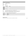


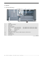
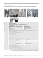
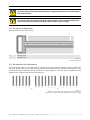
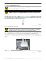
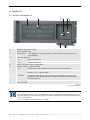
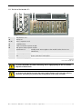
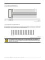
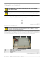
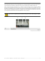
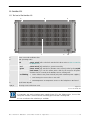
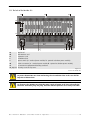
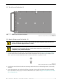
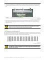
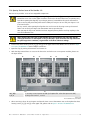
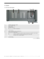
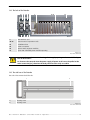
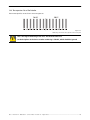
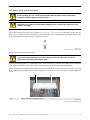

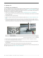
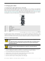
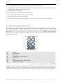
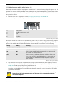
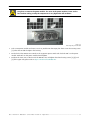
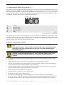
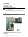

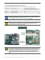
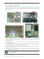
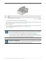

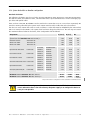
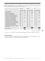
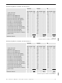
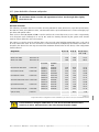
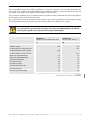
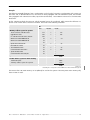
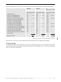
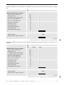
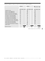
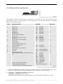


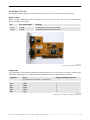


![CAST for PSI user`s manual [v07]](http://vs1.manualzilla.com/store/data/005903758_1-a858c2dfda3ffb28451a6ec48d1cfa02-150x150.png)
![OverView Control Manager user`s manual - operator [v04]](http://vs1.manualzilla.com/store/data/005659468_1-4c522981c7089838b286d7fbb1120c24-150x150.png)

![Multi Input Module for OverView D user`s manual [v07]](http://vs1.manualzilla.com/store/data/005713215_1-e2d53d24a0a93d32e9e353f3f6c133cd-150x150.png)