1
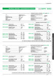
CAP 4 Elettrovalvole e valvole pneumatiche Solenoid and pneumatic valves 4.15 - G 1/2” Intenzionalmente bianca Intentional white elettrovalvola solenoid valve 3/2vie solenoide 22mm G 1/2” 3/2ways 22mm solenoid G 1/2” N.C.+N.A. N.C.+N.O. comando elettropneumatico indiretto riposizionamento a SCELTA SINGLE SOLENOID - INDIRECT PILOT RETURN AT CUSTOMER’S CHOICE COD: MATERIALI MATERIALS AC9 All er lim Po lic tal s Me read th All llic ta me 2 2 Tutto polimero = All polymer Filetti metallici - Corpo polimero = Metallic thread - Polymer body Tutto metallico = All metallic - lic tal s Me read th All er lim Po 3 All llic ta me 2 std = Pilot Pilot 12 0 10 2 1 3 1 Asservita = 10 = External supply N.C. = 10 N.C. = Tipo TYPE 2 0 1 3 12N.A. = N.O. = 10 ritorno return 2 12 12 I II 1 3 std 10 2 1 3 155 - Molla meccanica= Mechanical spring= 10 21 29 g1/2" x 2 1 = = = 30 2 1 3 12 3 4 22 12 4.15 123 109 2 12 Va.c. 3.5 VA= 24 Va.c. 5 VA = 115Va.c. 5 VA = 230Va.c. 5 VA = Opt. Senza bobina Without solenoid 012C 024C 012A 024A 115A 230A comando manuale manual override Standard (con cacciavite) = Standard (with screwdriver) = Comando manuale a Leva = Lever manual override = Q4,3 x 2 22 L 47,5 connettore a parte 15 - connector is not included T - T ipi eLva di riposizionamento ypes of evo00012_ 3_2 nc 1_2 mono mp Ø10_cataLogo OPERATION The solenoid valve can open and close a piping with fluid in presence of an electric piloting signal. USE This 3/2 way solenoid valve allows the interception of fluid or the piloting of single acting cylinders. Its high flow and reliability, make it ideal for the most complex automations. Subject to changes without prior notice g1/2" 2 STD = 0000 FUNZIONAMENTO L’elettrovalvola svolge la funzione di apertura o chiusura di un condotto in presenza di un segnale elettrico di pilotaggio. IMPIEGO La 3/2 vie nasce per l’intercettazione di fluidi e per il comando di cilindri a semplice effetto. L’elevata affidabilità e portata ne fanno la scelta ideale per le più complesse automazioni. Con riserva di modifica senza preavviso 46 24 Vd.c. 3.5 W = 26 AC 12 Vd.c. 6 W = 4 13 DC 69,5 40 23 Voltaggio Voltage 1 3 I Molla Meccanica II Spring Molla Pneumatica Pneumatic Spring N.C. = 12 N.C. = N.A. = 10 N.O. = 2 10 1 3 N.C. = N.C. = 2 10 12 1 3 12 N.A. = N.O. = = A limentazione / Supply 2 = Utilizzo / Output 3 = Scarico / Exhaust 12 = Linea di pilotaggio N.C. / Pilot line N.C. 12 10 1 10 = Linea di pilotaggio N.A. / Pilot line N.O. 2 2 3.15/010 return 1 3 1 3 Fluido Fluid Fissaggio Fixing Attacchi Connections G 1/2” Sistema di commutazione Switching system Spola Portata e diametro nominale (6 bar) Nominal rated flow and diameter (6 bar) Pressione di esercizio Working pressure Tempo commutazione Switching time Tempo disinserzione Unswitching time Temperatura ambiente-fluido Ambient-fluid temperature range -10 ÷ 60ºC Materiale corpo/connessioni Body / thread material Materiale guarnizioni Seals material NBR Durata dell’inserimento ED Lasting of connection ED 100% ED Grado di protezione (con connettore) Protection degree (with connector) IP 65 (DIN 40050) Aria compressa filtrata, lubrificata o non Filtered lubricated or not lubricated air Mediante fori passanti nel corpo ø4 By holes through the body ø4 Peso (senza connettore) Stampato - Printed : Weight 23/03/2007 (without connector) 1I =2÷10 bar 1I =2÷8 bar 1I =25/30 ms - Spool 1500 Nl/min I1I =2÷10 bar I1I =2÷8 bar I1I =25/30 ms 5 ÷ 60ºC - Metallic 0.325 Kg 4.15 / 010 Diagramma di portata nominale - Diagram of normal rated flow Flow Rate p=1 bar [Nl/min] 5000 4000 3000 1= 7 bar 1= 6 bar 1= 5 bar 1000 1= 4 bar 1= 1 bar Pressure [bar] 2 3 4 5 6 7 IO E G Standard coils 30 mm 22 mm DC Power 12 V Cod: AC Power Cod: DC Power A Cod: Power 6 W DA005001 3.5 VA BOB00028 3.5 W DC030100 3.3 VA DC 24 V 3.5 W DA005101 5 VA BOB00045 3.5 W DC030200 3.3 VA DC 2 4 Accessori per valvole 3/2 vie G1/8” - Connettori G A LT A O LT V O ±10% V 1= 2 bar 1 G 1= 3 bar 2000 Bobine elettriche standard - d i sp o n i b i l i 115 V 5 VA DA010803 3.3 VA DC 230 V 5 VA BOB00064 3.3 VA DC 3/2 way g 1/8” valves accessories - Available Connectors DIN 43650 - 22 mm Con LED Standard Type COD: CNK00022 - COD: 0 DIN 4 5 36 With LED CNK000 STD:0÷230V (no led) Led+VDR 12÷24 V Led+VDR 115 V Led+VDR 230 V = = = = 22 18 29 44 NORME DI USO E MANUTENZIONE USE AND MAINTENANCE Questa apparecchiatura rispetta severe specifiche qualitative tuttavia un uso improprio od inadeguato potrebbe comprometterne il funzionamento e decadere la garanzia. NON E’ UN DISPOSITIVO DI SICUREZZA This unit complies with high quality specifications. The incorrect use or misuse of this unit will compromise performance and will invalidate the warranty. THIS UNIT IS NOT A SAFETY DEVICE aTTenzione: prima di ogni operazione assicurarsi che il componente non sia in pressione o sotto tensione. Ristabilire entrambi solo dopo aver controllato l’esattezza delle connessioni. sconsigliaTo usare fileTTaTure coniche su fileT- Warning: before this unit is used and any maintenance work is done please ensure that you have made the correct connections and that the unit is not under electricity and pressurised. Pressure and electric power can be restored when the connections are checked. Tapered Threads noT advisable on polymer Threads TaTure in polimero 4.15 / 011 KPM italy +39.059.698681 Stampato - Printed : 26 / 05 / 2007 Subject to changes without prior notice - Con riserva di modifica senza preavviso Tipo standard elettrovalvola solenoid valve 3/2vie solenoide 22mm G 1/2” 3/2ways 22mm solenoid G 1/2” DOPPIO comando elettropneumatico indiretto DOUBLE SOLENOID - INDIRECT PILOT MATERIALI MATERIALS COD: AC9 All er lim Po lic tal s Me read th All llic ta me 022 Tutto polimero = All polymer Filetti metallici - Corpo polimero = Metallic thread - Polymer body Tutto metallico = All metallic - lic tal s Me read th All er lim Po 3 All llic ta me 2 std = 12 20 10 2 Differenziale = 10 Differential = Pilot Pilot 1 3 12 1 3 12 2 Asservita = External10supply = 21 1 3 12 Va.c. 3.5 VA= 24 Va.c. 5 VA = 115Va.c. 5 VA = 230Va.c. 5 VA = 30 138 L comando manuale manual override g1/2" 26 2 Q4,3 x 2 22 47,5 OPERATION The solenoid valve can open and close a piping with fluid in presence of an electric piloting signal. USE This 3/2 way solenoid valve allows the interception of fluid or the piloting of single acting cylinders. the diffeIn the condition of simultaneous piloting of . rential type switches itself in connettore a parte 46 - connector is not included - Types Tipi di pilotaggio of piloting Differenziale evo00023_eLva 3_2 1_2 biSt Ø10_cataLogo STANDARD Differential I = A limentazione / Supply 2 = Utilizzo / Output 3 = Scarico 1 3 / Exhaust 12 10 = Linea di pilotaggio / Pilot line 10 12 10 1 3 II 3.15/040 1 2 2 12 Subject to changes without prior notice 4.15 167 STD = 0000 Standard (con cacciavite) = Standard (with screwdriver) = Comando manuale a Leva = Lever manual override = 51,5 29 230 FUNZIONAMENTO L’elettrovalvola in presenza di un segnale elettrico di pilotaggio permette l’apertura o la chiusura di un condotto con fluido. IMPIEGO La 3/2 vie nasce per l’intercettazione di fluidi e per il comando di cilindri a semplice effetto. L’elevata affidabilità e portata ne fanno la scelta ideale per le più complesse automazioni. La versione differenziale nella condizione di pilotaggio si commuta in . simultaneo di Con riserva di modifica senza preavviso = = 22 g 1/2 x 2 012A 024A 115A 230A 46 Opt. Senza bobina Without solenoid 012C 024C 4 13 24 Vd.c. 3.5 W = 23 AC 12 Vd.c. 6 W = 69,5 DC 39,5 Voltaggio Voltage 1 3 Fluido Fluid Fissaggio Fixing Attacchi Connections G 1/2” Sistema di commutazione Switching system Spola Portata e diametro nominale (6 bar) Nominal rated flow and diameter (6 bar) Pressione di esercizio Working pressure Tempo commutazione Switching time Tempo disinserzione Unswitching time Temperatura ambiente-fluido Ambient-fluid temperature range -10 ÷ 60ºC Materiale corpo/connessioni Body / thread material Materiale guarnizioni Seals material NBR Durata dell’inserimento ED Lasting of connection ED 100% ED Grado di protezione (con connettore) Protection degree (with connector) IP 65 Aria compressa filtrata, lubrificata o non Filtered lubricated or not lubricated air Mediante fori passanti nel corpo ø4 By holes through the body ø4 Peso (senza connettore) Stampato - Printed : Weight 23/03/2007 (without connector) 1I =2÷10 bar 1I =2÷8 bar 1I =25/30 ms Spool 1500 Nl/min I1I =2÷10 bar I1I =2÷8 bar I1I =25/30 ms 5 ÷ 60ºC Metallic (DIN 40050) 0.322 Kg 4.15 / 020 Diagramma di portata nominale - Diagram of normal rated flow Flow Rate p=1 bar [Nl/min] 5000 4000 3000 1= 7 bar 1= 6 bar 1= 5 bar 1000 1= 4 bar 1= 1 bar Pressure [bar] 2 3 4 5 6 7 IO E G Standard coils 30 mm 22 mm DC Power 12 V Cod: AC Power Cod: DC Power A Cod: Power 6 W DA005001 3.5 VA BOB00028 3.5 W DC030100 3.3 VA DC 24 V 3.5 W DA005101 5 VA BOB00045 3.5 W DC030200 3.3 VA DC 2 4 Accessori per valvole 3/2 vie G1/8” - Connettori G A LT A O LT V O ±10% V 1= 2 bar 1 G 1= 3 bar 2000 Bobine elettriche standard - d i sp o n i b i l i 115 V 5 VA DA010803 3.3 VA DC 230 V 5 VA BOB00064 3.3 VA DC 3/2 way g 1/8” valves accessories - Available Connectors DIN 43650 - 22 mm Con LED Standard Type COD: CNK00022 - COD: 0 DIN 4 5 36 With LED CNK000 STD:0÷230V (no led) Led+VDR 12÷24 V Led+VDR 115 V Led+VDR 230 V = = = = 22 18 29 44 NORME DI USO E MANUTENZIONE USE AND MAINTENANCE Questa apparecchiatura rispetta severe specifiche qualitative tuttavia un uso improprio od inadeguato potrebbe comprometterne il funzionamento e decadere la garanzia. NON E’ UN DISPOSITIVO DI SICUREZZA This unit complies with high quality specifications. The incorrect use or misuse of this unit will compromise performance and will invalidate the warranty. THIS UNIT IS NOT A SAFETY DEVICE aTTenzione: prima di ogni operazione assicurarsi che il componente non sia in pressione o sotto tensione. Ristabilire entrambi solo dopo aver controllato l’esattezza delle connessioni. sconsigliaTo usare fileTTaTure coniche su fileT- Warning: before this unit is used and any maintenance work is done please ensure that you have made the correct connections and that the unit is not under electricity and pressurised. Pressure and electric power can be restored when the connections are checked. Tapered Threads noT advisable on polymer Threads TaTure in polimero 4.15 / 021 KPM italy +39.059.698681 Stampato - Printed : 26 / 05 / 2007 Subject to changes without prior notice - Con riserva di modifica senza preavviso Tipo standard G1/2” G1/2” elettrovalvola 5/2 vie solenoide 22mm solenoid valve 5/2 way 22mm solenoid doppio comando elettropneumatico comando elettropneumatico indiretto indiretto riposizionamento a molla pneumatica SINGLE SOLENOID - INDIRECT PILOT double SOLENOID - INDIRECT pilot PNEUMATIC SPRING RETURN AC MATERIALI MATERIALS COD: All er lim Po lic tal s Me read th All llic ta me 0022 Tutto polimero = All polymer Filetti metallici - Corpo polimero = Metallic thread - Polymer body Tutto metallico = All metallic - lic tal s Me read th All er lim Po 9 All llic ta me 2 std = 12 0 10 2 Differenziale = 10 Differential = Pilot Pilot 1 3 12 1 3 12 2 Asservita = External10supply = 4 1 5 3 115Va.c. 5 VA = 230Va.c. 5 VA = 30 22 = 58 22 L Q4,5 x 2 comando manuale manual override 29 4 36,5 26 27 Q4,3 x 2 22 71,5 15 I OPERATION The 5/2 solenoid valve can open and close 2 distint piping with fluid in presence of an electric piloting signal. USE This 5/2 way solenoid valve allows the direct piloting of double acting cylinders. In the condition of simultaneous piloting of 14 and 12 the differential type switches itself in 14 . II connettore a parte - connector is not included - Types Tipi di pilotaggio Differenziale Differential STANDARD of piloting Alimentazione 12 12 I 551133 12 14 = Supply 2 = Output 5 3 = Exhaust Scarichi = Linea di pilotaggio = 12 14 513 II 1 4 = 3.15/070= 44 22 evg00003_eLva 5_2 1_2 mono mp Ø10_cataLogo 4 2 Utilizzi 14 Subject to changes without prior notice g 1/2" x 2 2 4 13 17 Standard (con cacciavite) = Standard (with screwdriver) = Comando manuale a Leva = Lever manual override = 7 46 STD = 0000 FUNZIONAMENTO L’elettrovalvola 5/2 in presenza di un segnale elettrico di pilotaggio permette l’apertura e la chiusura di 2 condotti distinti. IMPIEGO Questa valvola 5/2 vie permette il pilotaggio diretto di cilindri a doppio effetto. La versione differenziale nella condizione di pilotaggio simultaneo di 14 e 12 si commuta in 14 . Con riserva di modifica senza preavviso 4.15 178 146,5 132 Senza bobina Without solenoid Opt. = g1/2" x 3 012A 024A 115A 230A 15 16,5 12 Va.c. 3.5 VA= 24 Va.c. 5 VA = 012C 024C 13,5 24 Vd.c. 3.5 W = 23 AC 12 Vd.c. 6 W = 69,5 DC 39,5 Voltaggio Voltage 1 3 = Pilot line Fluido Fluid Fissaggio Fixing Attacchi Connections G 1/2” Sistema di commutazione Switching system Spola Portata e diametro nominale (6 bar) Nominal rated flow and diameter (6 bar) 2500 Nl/min Pressione di esercizio Working pressure * Pressione di esercizio con 2.2W * Working pressure with 2.2W Tempo commutazione-disinserzione Switching - Unswitching time Temperatura ambiente-fluido Ambient-fluid temperature range -10 ÷ 60ºC Materiale corpo/connessioni Body / thread material Materiale guarnizioni Seals material NBR Durata dell’inserimento ED Lasting of connection ED 100% ED Grado di protezione (con connettore) Protection degree (with connector) IP 65 Aria compressa filtrata, lubrificata o non Filtered lubricated or not lubricated air Mediante fori passanti nel corpo ø4 By holes through the body ø4 Peso (senza connettore) Stampato - Printed : Weight 23/03/2007 (without connector) Spool 1I =2.5÷10 bar I1I =3÷10 bar 1I =2.5÷8 bar I1I =3÷8 bar =18/23 ms =20/25 ms 5 ÷ 60ºC Metallic (DIN 40050) 0.260 Kg 4.15 / 050 Diagramma di portata nominale - Diagram of normal rated flow Flow Rate 4000 1= 7 bar 1= 6 bar 1= 5 bar 3000 1= 4 bar 1= 1 bar Pressure [bar] 1 3 2 4 5 IO E G 12 V 30 mm 22 mm DC Power AC Cod: Power DC Cod: Power Cod: 6 W DA005001 3.5 VA BOB00028 3.5 W DC030100 3.3 VA DC030600 115 V 5 VA DA010803 3.3 VA DC030900 230 V 5 VA BOB00064 3.3 VA DC031000 3 2 1 O P T I O N A L Montaggio in sottobase manifold Assembly of manifold bases Connettori - Connectors d DIN 43650 - 22 mm 1I 197 COD: 0 65 113,5 DIN 1 I1I IV = = STD:0÷230V (no led) Led+VDR 12÷24 V Led+VDR 115 V Led+VDR 230 V = = = = 22 18 29 44 manifold bases c 3 1 43 CNK000 22 Sottobasi manifold - 44 5 Power 24 V 3.5 W DA005101 5 VA BOB00045 3.5 W DC030200 3.3 VA DC030700 4 g 1/2" x 3 AC Cod: 2 4 7 6 G A LT A O LT V O ±10% V 1= 2 bar 1000 G 1= 3 bar 2000 Standard coils p=1 bar [Nl/min] 5000 Bobine elettriche standard - - Inlet base Base entrata Base chiusura - Closure base COD: SBK00102 47 140 III 1 COD: 128 SBK00103 b 6 Piastra prelievo I - Porting block APERTA - OPEN COD : 32 III 96 32 II Base intermedia - Middle base SBK00105 CHIUSA - CLOSED COD : Iv STK00039 a 4 3 2 1 NORME DI USO E MANUTENZIONE USE AND MAINTENANCE Questa apparecchiatura rispetta severe specifiche qualitative tuttavia un uso improprio od inadeguato potrebbe comprometterne il funzionamento e decadere la garanzia. NON E’ UN DISPOSITIVO DI SICUREZZA This unit complies with high quality specifications. The incorrect use or misuse of this unit will compromise performance and will invalidate the warranty. THIS UNIT IS NOT A SAFETY DEVICE aTTenzione: prima di ogni operazione assicurarsi che il componente non sia in pressione o sotto tensione. Ristabilire entrambi solo dopo aver controllato l’esattezza delle connessioni. sconsigliaTo usare fileTTaTure coniche su fileT- Warning: before this unit is used and any maintenance work is done please ensure that you have made the correct connections and that the unit is not under electricity and pressurised. Pressure and electric power can be restored when the connections are checked. Tapered Threads noT advisable on polymer Threads TaTure in polimero 4.15 / 051 KPM italy +39.059.698681 Stampato - Printed : 12/02/2007 Con riserva di modifica senza preavviso COD: Subject to changes without prior notice SBK00104 Kit per barra DIN - DIN fixing kit G1/2” G1/2” elettrovalvola 5/2 vie solenoide 22mm solenoid valve 5/2 way 22mm solenoid doppio comando comandoelettropneumatico elettropneumatico indiretto indiretto double SOLENOID SOLENOID--INDIRECT INDIRECTpilot pilot MATERIALI MATERIALS 022 AC COD: All er lim Po lic tal s Me read th All llic ta me Tutto polimero = All polymer Filetti metallici - Corpo polimero = Metallic thread - Polymer body Tutto metallico = All metallic - lic tal s Me read th All er lim Po 9 All llic ta me 2 std = 12 20 10 2 Differenziale = 10 Differential = 24 Vd.c. 3.5 W = 12 Va.c. 3.5 VA= 24 Va.c. 5 VA = 115Va.c. 5 VA = 230Va.c. 5 VA = = g1/2" x 3 012A 024A 115A 230A 4.15 STD = 0000 Standard (con cacciavite) = Standard (with screwdriver) = Comando manuale a Leva = Lever manual override = L Q4,5 x 2 29 comando manuale manual override 67 4 g 1/2" x 2 26 2 Q4,3 x 2 27 22 71,5 I OPERATION The 5/2 solenoid valve can open and close 2 distint piping with fluid in presence of an electric piloting signal. USE This 5/2 way solenoid valve allows the direct piloting of double acting cylinders. In the condition of simultaneous piloting of 14 and 12 the differential type switches itself in 14 . connettore a parte - connector is not included Differenziale sul 14 Differential 14 pilot line win STANDARD 4 2 II 46 - Types Tipi di pilotaggio 14 4 2 of piloting Alimentazione = 1 = Supply Utilizzi = 4 2 = Output 3 = Exhaust 3.15/100 = 5 12 14 Ø10_cataLogo 12 evg00004_eLva 5_2 1_2 biSt 513 Subject to changes without prior notice 52,5 254 191 162 FUNZIONAMENTO L’elettrovalvola 5/2 in presenza di un segnale elettrico di pilotaggio permette l’apertura e la chiusura di 2 condotti distinti. IMPIEGO Questa valvola 5/2 vie permette il pilotaggio diretto di cilindri a doppio effetto. La versione differenziale nella condizione di pilotaggio simultaneo di 14 e 12 si commuta in 14 . Con riserva di modifica senza preavviso = 58 46 Opt. Senza bobina Without solenoid 012C 024C 68,5 AC 12 Vd.c. 6 W = 3 39,5 23 Voltaggio Voltage 1 3 DC 1 5 60 30 Asservita = External10supply = 21 13,5 15 16,5 12 2 7 1 3 4 13 17 12 22 Pilot Pilot 1 3 I Scarichi 513 II Linea di pilotaggio = 12 14 = Pilot line Fluido Fluid Fissaggio Fixing Attacchi Connections G 1/2” Sistema di commutazione Switching system Spola Portata e diametro nominale (6 bar) Nominal rated flow and diameter (6 bar) 2500 Nl/min Pressione di esercizio Working pressure * Pressione di esercizio con 2.2W * Working pressure with 2.2W Tempo commutazione-disinserzione Switching - Unswitching time Temperatura ambiente-fluido Ambient-fluid temperature range -10 ÷ 60ºC Materiale corpo/connessioni Body / thread material Materiale guarnizioni Seals material NBR Durata dell’inserimento ED Lasting of connection ED 100% ED Grado di protezione (con connettore) Protection degree (with connector) IP 65 Aria compressa filtrata, lubrificata o non Filtered lubricated or not lubricated air Mediante fori passanti nel corpo ø4 By holes through the body ø4 Peso (senza connettore) Stampato - Printed : Weight 23/03/2007 (without connector) Spool 1I =2.5÷10 bar I1I =3÷10 bar 1I =2.5÷8 bar I1I =3÷8 bar =18/23 ms =20/25 ms 5 ÷ 60ºC Metallic (DIN 40050) 0.364 Kg 4.15 / 060 Diagramma di portata nominale - Diagram of normal rated flow Flow Rate 4000 1= 7 bar 1= 6 bar 1= 5 bar 3000 1= 4 bar 1= 3 bar 2000 1000 Standard coils p=1 bar [Nl/min] 5000 Bobine elettriche standard - 1= 1 bar Pressure [bar] 2 3 4 4 5 6 G IO E G A LT A O LT V O ±10% V 12 V 1= 2 bar 1 G 30 mm 22 mm DC AC Cod: Power Power AC Cod: Power Cod: 24 V 3.5 W DA005101 5 VA BOB00045 3.5 W DC030200 3.3 VA DC030700 115 V 5 VA DA010803 3.3 VA DC030900 230 V 5 VA BOB00064 3.3 VA DC031000 2 4 7 3 2 1 O P T I O N A L Connettori - Connectors DINd 43650 - 22 mm 1I 254 COD: 0 65 112,5 DIN 43 1 I1I IV c 3 1 CNK000 22 STD:0÷230V (no led) Led+VDR 12÷24 V Led+VDR 115 V Led+VDR 230 V Sottobasi manifold - 44 5 Power 6 W DA005001 3.5 VA BOB00028 3.5 W DC030100 3.3 VA DC030600 Montaggio in sottobase manifold Assembly of manifold bases g 1/2" x 3 DC Cod: = = = = 22 18 29 44 manifold bases - Inlet base Base entrata Base chiusura - Closure base COD: SBK00102 = = 47 140 Base intermedia - Middle base III 1 COD: SBK00103 128 II 6 b - Porting block APERTA - OPEN 96 32 Iv 32 Piastra prelievo III COD : SBK00105 CHIUSA - CLOSED COD : STK00039 a 4 3 2 1 NORME DI USO E MANUTENZIONE USE AND MAINTENANCE Questa apparecchiatura rispetta severe specifiche qualitative tuttavia un uso improprio od inadeguato potrebbe comprometterne il funzionamento e decadere la garanzia. NON E’ UN DISPOSITIVO DI SICUREZZA This unit complies with high quality specifications. The incorrect use or misuse of this unit will compromise performance and will invalidate the warranty. THIS UNIT IS NOT A SAFETY DEVICE aTTenzione: prima di ogni operazione assicurarsi che il componente non sia in pressione o sotto tensione. Ristabilire entrambi solo dopo aver controllato l’esattezza delle connessioni. sconsigliaTo usare fileTTaTure coniche su fileT- Warning: before this unit is used and any maintenance work is done please ensure that you have made the correct connections and that the unit is not under electricity and pressurised. Pressure and electric power can be restored when the connections are checked. Tapered Threads noT advisable on polymer Threads TaTure in polimero 4.15 / 061 KPM italy +39.059.698681 Stampato - Printed : 12/02/2007 Con riserva di modifica senza preavviso COD: Subject to changes without prior notice SBK00104 Kit per barra DIN - DIN fixing kit valvola pneumatica Pneumatic valve 3/2vie 3/2way G1/2” G1/2” N.C.+N.A. N.C.+N.O. comando pneumatico riposizionamento a SCELTA pneumatic PILOT RETURN AT CUSTOMER’S CHOICE 20 0000 AC9 CL MATERIALI MATERIALS COD: All er lim Po lic tal s Me read th All llic ta me Tutto polimero = All polymer Filetti metallici - Corpo polimero = Metallic thread - Polymer body Tutto metallico = All metallic - lic tal s Me read th All er lim Po 20 All llic ta me 2 N.C. = 10 N.C. = Tipo TYPE 12 2 12N.A. = N.O. = 12 I 12 II 1 3 std 10 2 1 3 3 3 1 = 0 Molla meccanica= Mechanical spring= 10 A 30 2 = = 10 ritorno return 0 1 3 1 3 21 29 g1/2" x 2 4.15 102,5 46 FUNZIONAMENTO Questa valvola svolge la funzione di apertura o chiusura di un condotto in presenza di un segnale pneumatico di pilotaggio. IMPIEGO La 3/2 vie nasce per l’intercettazione di fluidi e per il comando diretto di cilindri a semplice effetto. Il pilotaggio pneumatico permette un assoluto grado di isolamento elettrico. CARATTERISTICHE -Ideale per ambienti aggressivi. -Montaggio avviene singolarmente attacco rapido Ø4 fast connection Ø4 g1/2" 22 33,5 Con riserva di modifica senza preavviso Subject to changes without prior notice OPERATION This valve can open or close a piping with a pneumatic piloting signal. USE This 3/2 pneumatic valve enables allows the interception of fluid or the direct piloting of single acting cylinders. The pneumatic piloting allows an absolute degree of electric insulation. PERFORMANCES -Design for aggressive or corrosive ambient. -Assembly can be in a singular way. 47,5 15 I II T - T ipi di riposizionamento ypes vpX00002_vaLp 3_2 nc 1_2 mono mp_cataLogo I Molla Meccanica II Spring Molla Pneumatica Pneumatic Spring N.C. = 12 N.C. = N.A. = 10 N.O. = 2 10 2 N.C. = N.C. = 12 10 1 3 1 3 2 2 12 N.A. = N.O. = 10 Fluid of return 3.15/020 1 = A limentazione / Supply 2 = Utilizzo / Output 3 = Scarico / Exhaust 10 = Linea di pilotaggio N.A. / Pilot line N.O. 12 = Linea di pilotaggio N.C. / Pilot line N.C. 12 1 3 1 3 Fluido 4 Q4,3 x 2 13 26 2 Aria compressa filtrata, lubrificata o non Filtered lubricated or not lubricated air Fissaggio Fixing Mediante fori passanti nel corpo ø4 By holes through the body ø4 Attacchi Connections G 1/2” Sistema di commutazione Switching system Spola Spool Portata e diametro nominale Nominal rated flow and diameter 1500 Nl/min Pressione di esercizio Working pressure Pressione di pilotaggio Pilot pressure 0÷10 bar Vedi retro Please turn over Tempo commutazione-disinserzione Switching - Unswitching time Temperatura ambiente-fluido Ambient-fluid temperature range Materiale corpo / filettature Body / threads material Materiale guarnizioni Seals material NBR Peso Weight Stampato - Printed : 28/03/2007 = 15/23 ms -10 ÷ 60ºC = 17/28 ms 5 ÷ 60ºC Metallic 0.285 kg 4.15 / 500 Diagramma di portata nominale - Diagram of normal rated flow Flow Rate 14 p=1 bar [Nl/min] 5000 4000 1= 7 bar 1= 6 bar 1= 5 bar 3000 1= 4 bar 1000 Pressure [bar] 2 2 1.8 1.6 1.4 1.2 1= 1 bar 1 2.8 2.6 2.4 2.2 1= 2 bar 3 4 5 6 7 [bar] 3 1= 3 bar 2000 Pressione di pilotaggio - Pilot pressure 1 0.8 0.6 0.4 0.2 2 4 0 [bar] 1 2 3 4 5 6 7 8 9 10 1 USE AND MAINTENANCE Questa apparecchiatura rispetta severe specifiche qualitative tuttavia un uso improprio od inadeguato potrebbe comprometterne il funzionamento e decadere la garanzia. NON E’ UN DISPOSITIVO DI SICUREZZA This unit complies with high quality specifications. The incorrect use or misuse of this unit will compromise performance and will invalidate the warranty. THIS UNIT IS NOT A SAFETY DEVICE aTTenzione: prima di ogni operazione assicurarsi che il componente non sia in pressione. Ristabilirla solo dopo aver controllato l’esattezza delle connessioni. sconsigliaTo usare fileTTaTure coniche su fileT- Warning: before this unit is used and any maintenance work is done please ensure that you have made the correct connections, and that the unit is not live and pressurised. Pressure can be restored when the connections are checked. Tapered Threads noT advisable on polymer Threads TaTure in polimero 4.15 / 501 Stampato - Printed : 12/02/2007 Con riserva di modifica senza preavviso NORME DI USO E MANUTENZIONE Subject to changes without prior notice O P T I O N A L 3/2vie 3/2ways valvola pneumatica Pneumatic valve G1/2” G1/2” ggio lota i pi NE d loting comando PNEUMATICO diretto S S IO riposizionamento a molla meccanica ASSA PRE RESSURe pi P B LOW PNEUMATIC DIRECT PILOT mechanical spring RETURN AL All er lim Po lic tal s Me read th All llic ta me 20 Tutto polimero = All polymer Filetti metallici - Corpo polimero = Metallic thread - Polymer body Tutto metallico = All metallic Monostabile Monostable = = 684 Bistabile Bistable = = 685 Funzione Function 2 10 12 3/2 N.C. 3/2 N.C. = 0000 3/2 N.A. 3/2 N.O. = 1000 8 lic tal s Me read th All er lim Po All llic ta me 1 3 2 12 10 4.15 1 3 Ø25 1 3 = = 30 Tipo TYPE MATERIALI MATERIALS COD: Q4,3 x 2 FUNZIONAMENTO Questa valvola svolge la funzione di apertura o chiusura di un condotto in presenza di un comando di pilotaggio pneumatico IMPIEGO La 3/2 vie nasce per il comando diretto di attuatori a semplice effetto. L’elevata affidabilità e portata ne fanno la scelta ideale per le più complesse automazioni. CARATTERISTICHE -Pilotaggio anche a bassa pressione 29 46 137 attacco rapido Ø4 fast connection Ø4 47,5 13 22,5 OPERATION This valve can open and close a piping with fluid in presence of a pneumatic piloting. USE This 3/2 way solenoid valve allows the direct piloting of single acting actuators. Its high flow and reliability, make it ideal for the most complex automations. PERFORMANCES -Always reliability in low pressure piloting way 2 g 1/2" 37 Logica - Logic vpd00043_v apn 3_23/2 naN.O. 1_2 1_2 mono baSSa preSS metaL Subject to changes without prior notice 3/2 N.C. 1 2 12 10 1 3 12 / Supply / Output 3 / Exhaust = Scarico 10 = Linea di pilotaggio N.A. / Pilot line N.O. 1 3 12 = Linea di pilotaggio N.C. / Pilot line N.C. Fluid Fluido Aria compressa filtrata, lubrificata o non Filtered lubricated or not lubricated air Fixing Fissaggio Con riserva di modifica senza preavviso 2 10 = A limentazione 2 = Utilizzo Mediante fori passanti nel corpo ø4 By holes through the body ø4 Attacchi Connections G 1/2” Sistema di commutazione Switching system Spola Portata e diametro nominale (6 bar) Nominal rated flow and diameter (6 bar) Pressione di esercizio / pilotaggio Working pressure / piloting 0 ÷ 10 bar / 0.5 bar min Temperatura ambiente-fluido Ambient-fluid temperature range -10 ÷ 60 ºC Materiale corpo / connessioni Body / thread material Materiale guarnizioni Seals material NBR Peso (senza connettore) Stampato - Printed : Weight 01/05/2007 (without connector) Spool 1500 Nl/min 5 ÷ 60 ºC Metallic 0.176 Kg 4.15 / 510 Diagramma di portata nominale - Diagram of normal rated flow Flow Rate p=1 bar [Nl/min] 5000 4000 3000 1= 7 bar 1= 6 bar 1= 5 bar 1= 4 bar 1= 3 bar 2000 1000 USO - USE 1= 2 bar 1= 1 bar Pressure [bar] 1 3 2 4 5 6 7 2 4 Versione BISTABILE - Bistable version Sottobasi manifold - manifold bases - Inlet base Base entrata I1I COD: Base intermedia - Middle base III 1 COD: IV 1 Base chiusura - Closure base COD: Piastra prelievo - Porting block APERTA - OPEN 1 COD : Ø25 = = 30 3 Q4,3 X 2 CHIUSA - CLOSED COD : g 1/2" x 2 29 Kit per barra DIN - DIN fixing kit COD: 46 Flangia fissaggio - Plate mounting COD: 195,5 1 2 2 96 10 12 1 3 = A limentazione / Supply 2 = Utilizzo / Output 3 / Exhaust = Scarico 10 = Linea di pilotaggio N.A. / Pilot line N.O. 12 = Linea di pilotaggio N.C. / Pilot line N.C. vpd00044_v apn 3_2 na 1_2 1_2 biSt baSSa preSS metaL NORME DI USO E MANUTENZIONE USE AND MAINTENANCE Questa apparecchiatura rispetta severe specifiche qualitative tuttavia un uso improprio od inadeguato potrebbe comprometterne il funzionamento e decadere la garanzia. NON E’ UN DISPOSITIVO DI SICUREZZA This unit complies with high quality specifications. The incorrect use or misuse of this unit will compromise performance and will invalidate the warranty. THIS UNIT IS NOT A SAFETY DEVICE aTTenzione: prima di ogni operazione assicurarsi che il componente non sia in pressione. Ristabilirla solo dopo aver controllato l’esattezza delle connessioni. sconsigliaTo usare fileTTaTure coniche su fileT- Warning: before this unit is used and any maintenance work is done please ensure that you have made the correct connections, and that the unit is not live and pressurised. Pressure can be restored when the connections are checked. Tapered Threads noT advisable on polymer Threads TaTure in polimero 4.15 / 511 KPM italy +39.059.698681 Stampato - Printed : 01/05/2007 Subject to changes without prior notice g 1/2" doppio comando PNEUMATICO diretto double PNEUMATIC DIRECT PILOT Con riserva di modifica senza preavviso 13 47,5 22,5 attacco rapido Ø4 fast connection Ø4 Stk00001 valvola pneumatica Pneumatic valve 3/2vie 3/2ways G1/2” G1/2” DOPPIO comando pneumatico DOUBLE pneumatic PILOT 2 0000 0 AC9 CL MATERIALI MATERIALS COD: All er lim Po lic tal s Me read th All llic ta me Tutto polimero = All polymer Filetti metallici - Corpo polimero = Metallic thread - Polymer body Tutto metallico = All metallic - lic tal s Me read th All er lim Po 22 All llic ta me 2 2 1 3 12 1 3 10 = std 0 Differenziale = 10 Differential = 1 3 = = 1 29 g1/2" x 2 30 Pilot Pilot 12 4.15 43 127 Con riserva di modifica senza preavviso Subject to changes without prior notice = = 30 4 22 Q4,3 x 2 33,5 47,5 I 33,5 II - Types T vpX00003_vaLp 3_2 1_2 biSt ipi di pilotaggio Differenziale Differential STANDARD I = A limentazione / Supply 2 = Utilizzo / Output 3 = Scarico 1 3 / Exhaust 12 10 = Linea di pilotaggio / Pilot line Fluid 10 12 10 12 1 3 II 3.15/060 of piloting 1 2 2 Fluido g1/2" 2 17 attacco rapido Ø4 fast connection Ø4 22,5 OPERATION This valve can open or close a piping with a pneumatic piloting signal. USE This 3/2 pneumatic valve enables allows the interception of fluid or the direct piloting of single acting cylinders. The pneumatic piloting allows an absolute degree of electric insulation. PERFORMANCES -Design for aggressive or corrosive ambient. -Assembly can be in a singular way. In the condition of simultaneous piloting of the diffe. rential type switches itself in 46 FUNZIONAMENTO Questa valvola svolge la funzione di apertura o chiusura di un condotto in presenza di un segnale pneumatico di pilotaggio. IMPIEGO La 3/2 vie nasce per l’intercettazione di fluidi e per il comando diretto di cilindri a semplice effetto. Il pilotaggio pneumatico permette un assoluto grado di isolamento elettrico. CARATTERISTICHE -Ideale per ambienti aggressivi. -Montaggio avviene singolarmente La versione differenziale nella condizione di pilotaggio si commuta in . simultaneo di Aria compressa filtrata, lubrificata o non Filtered lubricated or not lubricated air Fissaggio Fixing Mediante fori passanti nel corpo ø4 By holes through the body ø4 Attacchi Connections G 1/2” Sistema di commutazione Switching system Spola Spool Portata e diametro nominale Nominal rated flow and diameter 1500 Nl/min Pressione di esercizio Working pressure Pressione di pilotaggio Pilot pressure 0÷10 bar Vedi retro Please turn over Tempo commutazione-disinserzione Switching - Unswitching time Temperatura ambiente-fluido Ambient-fluid temperature range Materiale corpo / filettature Body / threads material Materiale guarnizioni Seals material NBR Peso Weight Stampato - Printed : 28/03/2007 = 15/23 ms -10 ÷ 60ºC = 17/28 ms 5 ÷ 60ºC Metallic 0.270 kg 4.15 / 520 Diagramma di portata nominale - Diagram of normal rated flow Flow Rate 4000 3000 [bar] p=1 bar [Nl/min] 5000 1= 7 bar 1= 6 bar 1= 5 bar 1= 4 bar 1= 3 bar 2000 1000 Pressione di pilotaggio - Pilot pressure 1= 1 bar Pressure [bar] 2 1.8 1.6 pe ial ty rent Dif fe ype rd t nda Sta 1.4 1.2 1 1= 2 bar 1 2 3 4 5 6 7 0.8 0.4 2 4 12 12 14 0.6 0.2 [bar] 0 1 2 3 4 5 6 7 8 9 10 1 USE AND MAINTENANCE Questa apparecchiatura rispetta severe specifiche qualitative tuttavia un uso improprio od inadeguato potrebbe comprometterne il funzionamento e decadere la garanzia. NON E’ UN DISPOSITIVO DI SICUREZZA This unit complies with high quality specifications. The incorrect use or misuse of this unit will compromise performance and will invalidate the warranty. THIS UNIT IS NOT A SAFETY DEVICE aTTenzione: prima di ogni operazione assicurarsi che il componente non sia in pressione. Ristabilirla solo dopo aver controllato l’esattezza delle connessioni. sconsigliaTo usare fileTTaTure coniche su fileT- Warning: before this unit is used and any maintenance work is done please ensure that you have made the correct connections, and that the unit is not live and pressurised. Pressure can be restored when the connections are checked. Tapered Threads noT advisable on polymer Threads TaTure in polimero 4.15 / 521 Stampato - Printed : 12/02/2007 Con riserva di modifica senza preavviso NORME DI USO E MANUTENZIONE Subject to changes without prior notice O P T I O N A L valvola pneumatica Pneumatic valve 5/2vie 5/2ways G 1/2” G 1/2” comando pneumatico diretto riposizionamento a molla pneumatica DIRECT pneumatic PILOT PNEUMATIC SPRING RETURN MATERIALI MATERIALS ritorno return 12 12 50 AC CM COD: All er lim Po lic tal s Me read th All llic ta me 2 I II 20 0000 Tutto polimero = All polymer Filetti metallici - Corpo polimero = Metallic thread - Polymer body Tutto metallico = All metallic std 10 2 1 3 = - lic tal s Me read th All er lim Po 9 All llic ta me 0 Molla meccanica= 10 Mechanical spring= A 5 1 3 = g1/2" x 3 = 58 22 13,5 15 16,5 30 1 3 4.15 FUNZIONAMENTO Questa valvola svolge la funzione di apertura o chiusura di un condotto in presenza di un segnale pneumatico di pilotaggio. IMPIEGO La 5/2 vie nasce per il comando diretto di cilindri a doppio effetto. Il pilotaggio pneumatico permette un assoluto grado di isolamento elettrico. CARATTERISTICHE -Ideale per ambienti aggressivi. -Montaggio sia su base Manifold che singolarmente. Q4,5 x 2 attacco rapido Ø4 fast connection Ø4 Subject to changes without prior notice g1/2" x 2 26 4 13 17 27 33,5 22 71,5 15 II vpg00001_vaLp 5_2 1_2 mono mp - Types Tipi di riposizionamento 3.15/080 of return Molla Meccanica Molla Pneumatica I Pneumatic Spring II Spring 4 2 14 12 Fluid 2 14 12 513 513 Fluido 2 I 4 Con riserva di modifica senza preavviso 4 30 = = Q4,3 x 2 OPERATION This valve can open or close a piping with a pneumatic piloting signal. USE This 5/2 pneumatic valve enables the direct piloting of double acting cylinders. The pneumatic piloting allows an absolute degree of electric insulation. PERFORMANCES -Design for aggressive or corrosive ambient. -Assembly on Manifold bases or in a singular way. 36,5 29 7 46 126,5 1 = A limentazione / Supply 4 2 = Utilizzo / Output 5 3 = Scarico / Exhaust 14 12 = Linea di pilotaggio / Pilot line Aria compressa filtrata, lubrificata o non Filtered lubricated or not lubricated air Fissaggio Fixing Mediante fori passanti nel corpo ø4,5 By holes through the body ø4,5 Attacchi Connections G1/2” Sistema di commutazione Switching system Spola Spool Portata e diametro nominale Nominal rated flow and diameter Pressione di esercizio Working pressure 0÷10 bar Pressione di pilotaggio Pilot pressure Vedi retro Tempo commutazione-disinserzione Switching - Unswitching time Temperatura ambiente-fluido Ambient-fluid temperature range Materiale corpo / filettature Body / threads material Materiale guarnizioni Seals material NBR Peso Weight Stampato - Printed : 28/03/2007 2500 Nl/min Please turn over =18 ms -10 ÷ 60ºC = 18 ms 5 ÷ 60ºC Metallic 0.230 kg 4.15 / 530 Diagramma di portata nominale - Diagram of normal rated flow Flow Rate p=1 bar [Nl/min] 5000 4000 1= 7 bar 1= 6 bar 1= 5 bar 3000 1= 4 bar 14 1000 [bar] 2 1.8 1.6 1.4 1.2 3 4 4 5 6 7 1 Pressure 1 2 1= 1 bar 0.8 0.6 0.4 0.2 0 2 4 3 [bar] 2.8 2.6 2.4 2.2 1= 2 bar Standard coils 3 1= 3 bar 2000 Bobine elettriche standard - 2 1 Montaggio in sottobase manifold Assembly of manifold bases [bar] 1 2 3 4 5 6 7 8 9 10 1 O P T I O N A L d Sottobasi manifold - 145 - Inlet base Base entrata Base chiusura - Closure base COD: SBK00102 44 90 1 I1I IV manifold bases III 1 Base intermedia - Middle base c COD: g 1/2" x 3 5 1 SBK00103 3 = = 47 Piastra prelievo 140 - Porting block APERTA - OPEN COD : 128 SBK00105 CHIUSA - CLOSED COD : SBK00104 Kit per barra DIN - DIN fixing kit b 32 6 COD: STK00039 Iv Subject to changes without prior notice 32 96 III a 4 3 2 1 NORME DI USO E MANUTENZIONE USE AND MAINTENANCE Questa apparecchiatura rispetta severe specifiche qualitative tuttavia un uso improprio od inadeguato potrebbe comprometterne il funzionamento e decadere la garanzia. NON E’ UN DISPOSITIVO DI SICUREZZA This unit complies with high quality specifications. The incorrect use or misuse of this unit will compromise performance and will invalidate the warranty. THIS UNIT IS NOT A SAFETY DEVICE aTTenzione: prima di ogni operazione assicurarsi che il componente non sia in pressione. Ristabilirla solo dopo aver controllato l’esattezza delle connessioni. sconsigliaTo usare fileTTaTure coniche su fileT- Warning: before this unit is used and any maintenance work is done please ensure that you have made the correct connections, and that the unit is not live and pressurised. Pressure can be restored when the connections are checked. Tapered Threads noT advisable on polymer Threads TaTure in polimero 4.15 / 531 KPM italy +39.059.698681 Stampato - Printed : 12/02/2007 Con riserva di modifica senza preavviso II valvola pneumatica G1/2” Pneumatic valve G1/2” 5/2vie 5/2ways G 1/2” G 1/2” ggio lota i pi NE d loting comando PNEUMATICO diretto S S IO riposizionamento a molla meccanica ASSA PRE RESSURe pi P B LOW PNEUMATIC DIRECT PILOT mechanical spring RETURN AC All er lim Po lic tal s Me read th All llic ta me Tipo TYPE MATERIALI MATERIALS COD: 20 0000 Tutto polimero = All polymer Filetti metallici - Corpo polimero = Metallic thread - Polymer body Tutto metallico = All metallic Monostabile Monostable = = 684 Bistabile Bistable = = 685 8 lic tal s Me read th All er lim Po All llic ta me 15 16,5 Ø25 3 13,5 4.15 1 5 FUNZIONAMENTO Questa valvola svolge la funzione di apertura o chiusura di un 2 condotti distinti in presenza di un comando di pilotaggio. IMPIEGO La 5/2 vie nasce per il comando diretto di attuatori a doppio effetto. L’elevata affidabilità e portata ne fanno la scelta ideale per le più complesse automazioni. Q4,3 x 3 = G 1/2" x 3 = 7,3 46 30 Q4,5 x 2 22,5 58 36,5 29 17 OPERATION This valve can open and close 2 piping with fluid in presence of a mechanical piloting. USE This 5/2 way solenoid valve allows the direct piloting of double acting actuators. Its high flow and reliability, make it ideal for the most complex automations. 13 161 8 4 2 27 71,5 G 1/2 x 2 Logica - Logic Subject to changes without prior notice VPU00018_V APN 5_2 1_2 1_2 MONO BASSA PRESS METAL 4 14 12 513 Fluid Fluido Alimentazione = 1 = Supply Utilizzi = 4 2 = Output Scarichi = 5 3 = Exhaust Linea di pilotaggio = 14 = Pilot line Aria compressa filtrata, lubrificata o non Filtered lubricated or not lubricated air Fixing Fissaggio Con riserva di modifica senza preavviso 2 Mediante fori passanti nel corpo ø4 By holes through the body ø4 Attacchi Connections G 1/2” Sistema di commutazione Switching system Spola Portata e diametro nominale (6 bar) Nominal rated flow and diameter (6 bar) Pressione di esercizio / pilotaggio Working pressure / piloting 0 ÷ 10 bar / 0.5 bar min Temperatura ambiente-fluido Ambient-fluid temperature range -10 ÷ 60 ºC Materiale corpo / connessioni Body / thread material Materiale guarnizioni Seals material NBR Peso (senza connettore) Stampato - Printed : Weight 01/05/2007 (without connector) Spool 2500 Nl/min 5 ÷ 60 ºC Metallic 0.176 Kg 4.15 / 540 Diagramma di portata nominale - Diagram of normal rated flow Flow Rate p=1 bar [Nl/min] 5000 4000 3000 1= 7 bar 1= 6 bar 1= 5 bar 1= 4 bar 1= 3 bar 2000 1000 USO - USE 1= 2 bar 1= 1 bar Pressure [bar] 1 2 3 4 5 6 7 2 4 Versione BISTABILE - Bistable version Sottobasi manifold - 1 1II IV II1 III 1 manifold bases - Inlet base Base entrata - Inlet base Base entrata BaseCOD: chiusura - Closure base COD: SBK00102 Base intermedia - Middle base BaseCOD: intermedia - Middle base III 1 IV 1 BaseCOD: chiusura - Closure base SBK00103 COD: - Porting block Piastra prelievo APERTA - OPEN COD : 13,5 15 16,5 1 3 COD : SBK00104 Kit per barra DIN - DIN fixing kit Ø25 5 Q4,3 x 2 = COD: COD: G 1/2" x 3 = 58 STK00039 Flangia fissaggio - Plate mounting COD: 46 7,3 29 SBK00105 CHIUSA - CLOSED Stk00001 Q4,5 x 2 27 71,5 4 12 14 G 1/2" x 2 513 1 = Supply Alimentazione = Utilizzi = 4 2 = Output Scarichi = 5 3 = Exhaust 2 Linea di pilotaggio= 12 14 = Pilot line NORME DI USO E MANUTENZIONE USE AND MAINTENANCE Questa apparecchiatura rispetta severe specifiche qualitative tuttavia un uso improprio od inadeguato potrebbe comprometterne il funzionamento e decadere la garanzia. NON E’ UN DISPOSITIVO DI SICUREZZA This unit complies with high quality specifications. The incorrect use or misuse of this unit will compromise performance and will invalidate the warranty. THIS UNIT IS NOT A SAFETY DEVICE VPU00019_V APN 5_2 1_2 1_2 BIST BASSA PRESS METAL aTTenzione: prima di ogni operazione assicurarsi che il componente non sia in pressione. Ristabilirla solo dopo aver controllato l’esattezza delle connessioni. sconsigliaTo usare fileTTaTure coniche su fileT- Warning: before this unit is used and any maintenance work is done please ensure that you have made the correct connections, and that the unit is not live and pressurised. Pressure can be restored when the connections are checked. Tapered Threads noT advisable on polymer Threads TaTure in polimero 4.15 / 541 KPM italy +39.059.698681 Stampato - Printed : 01/05/2007 Con riserva di modifica senza preavviso 2 Subject to changes without prior notice doppio comando PNEUMATICO diretto double PNEUMATIC DIRECT PILOT 30 Attacco rapido Ø4 Fast connection Ø4 8 1 22,5 13 17 219,5 valvola pneumatica Pneumatic valve 5/2vie 5/2ways G 1/2” G 1/2” doppio comando pneumatico Double pneumatic pilot MATERIALI MATERIALS All er lim Po lic tal s Me read th All llic ta me 2 ritorno Pilot return Pilot 12 52 AC CM COD: 14 12 I II 20 0000 Tutto polimero = All polymer Filetti metallici - Corpo polimero = Metallic thread - Polymer body Tutto metallico = All metallic 4 - lic tal s Me read th All er lim Po 9 All llic ta me 2 2 513 1 3 std 12= = std 10 0 0 Molla meccanica= 10 Mechanical spring= A 1 3 5 3 g1/2" x 3 = 13,5 15 16,5 30 1 = 58 44 4.15 151 Con riserva di modifica senza preavviso Subject to changes without prior notice OPERATION This valve can open or close a piping with a pneumatic piloting signal. USE This 5/2 pneumatic valve enables the direct piloting of double acting cylinders. The pneumatic piloting allows an absolute degree of electric insulation. PERFORMANCES -Design for aggressive or corrosive ambient. -Assembly on Manifold bases or in a singular way. -In the condition of simultaneous piloting of the . differential type switches itself in 46 FUNZIONAMENTO Questa valvola svolge la funzione di apertura o chiusura di un condotto in presenza di un segnale pneumatico di pilotaggio. IMPIEGO La 5/2 vie nasce per il comando diretto di cilindri a doppio effetto. Il pilotaggio pneumatico permette un assoluto grado di isolamento elettrico. CARATTERISTICHE -Ideale per ambienti aggressivi. -Montaggio sia su base Manifold che singolarmente. -La versione differenziale nella condizione di pilotaggio si commuta in . simultaneo di 4 g1/2" x 2 2 27 Q4,3 x 2 33,5 4 13 17 26 = = 30 attacco rapido Ø4 fast connection Ø4 22 71,5 33,5 4 I I II II Differential Standard vpg00002_vaLp 5_2 1_2 biSt 4 2 12 14 4 Fluid 2 12 14 513 Fluido 58,5 29 7 Q4,5 x 2 513 1 = A limentazione / Supply 4 2 = Utilizzo / Output 5 3 = Scarico / Exhaust 3.15/110 14 12 = Linea di pilotaggio / Pilot line Aria compressa filtrata, lubrificata o non Filtered lubricated or not lubricated air Fissaggio Fixing Mediante fori passanti nel corpo ø4,5 By holes through the body ø4,5 Attacchi Connections G1/2” Sistema di commutazione Switching system Spola Spool Portata e diametro nominale Nominal rated flow and diameter Pressione di esercizio Working pressure 0÷10 bar Pressione di pilotaggio Pilot pressure Vedi retro Tempo commutazione-disinserzione Switching - Unswitching time Temperatura ambiente-fluido Ambient-fluid temperature range Materiale corpo / filettature Body / threads material Materiale guarnizioni Seals material NBR Peso Weight Stampato - Printed : 28/03/2007 2500 Nl/min Please turn over =18 ms -10 ÷ 60ºC = 18 ms 5 ÷ 60ºC Metallic 0.300 kg 4.15 / 550 Diagramma di portata nominale - Diagram of normal rated flow Flow Rate 4000 3000 2 1= 7 bar 1= 6 bar 1= 5 bar 1000 1= 4 bar 1.4 Pressure [bar] 3 4 4 5 6 7 1.2 1 Sta 12 14 nd 0.6 0.4 0.2 [bar] 0 2 4 3 12 e l typ pe y t ard ntia re Dif fe 0.8 1= 1 bar 2 1.6 1= 2 bar 1 1.8 1= 3 bar 2000 Standard coils [bar] p=1 bar [Nl/min] 5000 Bobine elettriche standard - 2 1 Montaggio in sottobase manifold Assembly of manifold bases 1 2 3 4 5 6 7 8 9 10 1 O P T I O N A L d Sottobasi manifold - 151 - Inlet base Base entrata Base chiusura - Closure base COD: SBK00102 90 1 I1I IV 44 III 1 Base intermedia - Middle base c COD: g 1/2" x 3 5 SBK00103 3 1 = = 47 Piastra prelievo 140 - Porting block APERTA - OPEN COD : SBK00105 CHIUSA - CLOSED 128 COD : SBK00104 - DIN fixing kit b Kit per barra DIN Subject to changes without prior notice STK00039 a 4 3 2 1 NORME DI USO E MANUTENZIONE USE AND MAINTENANCE Questa apparecchiatura rispetta severe specifiche qualitative tuttavia un uso improprio od inadeguato potrebbe comprometterne il funzionamento e decadere la garanzia. NON E’ UN DISPOSITIVO DI SICUREZZA This unit complies with high quality specifications. The incorrect use or misuse of this unit will compromise performance and will invalidate the warranty. THIS UNIT IS NOT A SAFETY DEVICE aTTenzione: prima di ogni operazione assicurarsi che il componente non sia in pressione. Ristabilirla solo dopo aver controllato l’esattezza delle connessioni. sconsigliaTo usare fileTTaTure coniche su fileT- Warning: before this unit is used and any maintenance work is done please ensure that you have made the correct connections, and that the unit is not live and pressurised. Pressure can be restored when the connections are checked. Tapered Threads noT advisable on polymer Threads TaTure in polimero 4.15 / 551 KPM italy +39.059.698681 Stampato - Printed : 12/02/2007 Con riserva di modifica senza preavviso 32 Iv COD: 96 III 32 6 II manifold bases