1
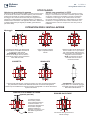
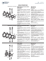
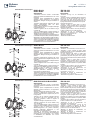
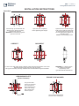
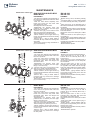
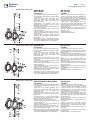
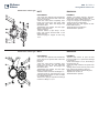
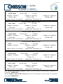
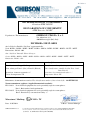
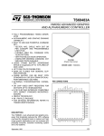
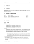
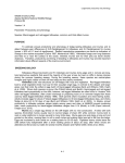
tel fax mail web p. 1 +39 051 835711 +39 051 830344 [email protected] ghibsonvalves.com p. 6 ITA ENG manuale di uso e manutenzione VALVOLE A FARFALLA instruction and maintenance manual BUTTERFLY VALVES p. 11 Certification MANUALE DI USO E MANUTENZIONE VALVOLE A FARFALLA Questo foglio di istruzioni deve essere conservato e consultato dal personale incaricato dell’installazione e della successiva manutenzione ordinaria e straordinaria. -- Prima dell’installazione o della manutenzione intercettare la -- Questo prodotto dovrà essere destinato solo per l’uso per linea a monte e a valle della valvola accertandosi che non ci il quale è stato espressamente prodotto, ogni altro utilizzo sia pressione. si considera potenzialmente pericoloso; in ogni caso il -- Non superare mai la massima pressione e i limiti di produttore non può essere considerato responsabile per temperatura indicati sulla marcatura dell’apparecchio. eventuali danni derivanti da usi non conformi. -- Il produttore non risponde per l’utilizzo improprio del prodotto; -- In caso di danneggiamento della guarnizione di tenuta l’installazione e la manutenzione devono essere effettuate da provvedere tempestivamente alla sostituzione affidandosi a personale specializzato. personale qualificato. --- ---- ISTRUZIONI GENERALI Prima della spedizione le superfici delle guarnizioni di tenuta vengono lubrificate con grassi e/o oli siliconici. Se per usi specifici, ad esempio idrogeno, ossigeno, cloro, ecc. le guarnizioni ed il disco non devono portare traccia di silicone, esso può essere asportato utilizzando opportuni solventi o altri adeguati prodotti per pulire e sgrassare. Prima di installare la valvola pulire la tubazione dallo sporco e dai residui di saldatura al fine di evitare di danneggiare il seggio di tenuta. Assicurarsi che le tubazioni non siano in tensione; in caso di presenza di correnti vaganti è necessario corredare la valvola di dispositivo antistatico. Non usare la valvola come leva per allargare le flange, ne potrebbe conseguire un danno alla sede durante l’installazione o il funzionamento. -- --- In caso di installazione su sistema nuovo, utilizzare la valvola come elemento distanziatore, fare una saldatura a punti di flangia e tubazione e, prima di ultimare la saldatura, rimuovere bulloni e valvola. Non ultimare la saldatura delle flange alla tubatura con la valvola fissata con bulloni tra le flange, perchè ciò porterà ad un serio danneggiamento da calore della sede. Sulle valvole a farfalla è presente una targhetta in cui sono riportati i dati che permettono di identificare il prodotto e le condizioni operative. La targhetta comprende inoltre la dichiarazione CE di conformità e, per le valvole destinate al funzionamento in atmosfera potenzialmente esplosiva, la marcatura specifica di protezione dalle esplosioni in accordo con la Direttiva 94/9/EC (ATEX). Solo per valvole marcate secondo la Direttiva 94/9/EC (ATEX) Le valvole marcate secondo la Direttiva 94/9/EC (ATEX) sono apparecchiature progettate per essere utilizzate, in conformità ai parametri operativi stabiliti, anche in luoghi in cui è probabile che si presentino atmosfere esplosive causate da miscele di aria e gas, vapori o nebbie o da miscele aria/polveri. CLASSIFICAZIONE e ZONE D’UTILIZZO Gruppo Categoria Zone Natura dell’atmosfera Protezione Massima temperatura di superficie II 2 121 Gas Polveri Sicurezza costruttiva “c” TX Nota sulla massima temperatura di superficie: questa non dipende dalla valvola ma solo dalle condizioni operative relative al fluido trasportato. La valvola in sé NON è quindi considerabile come sorgente di innesco. L’utilizzatore dovrà tenere in debito conto questo aspetto tecnico Zona 1 (gas) & 21 (polveri): l’atmosfera esplosiva si può presentare occasionalmente in condizioni di funzionamento normale. ATTENZIONE: per le valvole NON è previsto un funzionamento in luoghi dove l’atmosfera esplosiva è presente sempre, spesso o per lunghi periodi (zona 0). e dovrà adottare le opportune contromisure. Nel caso in cui la valvola (e la tubazione) venga “coimbentata” dovrà essere indicato, da parte dell’installatore, un adeguato tempo di attesa a decorrere dal fermo impianto, prima di procedere alla rimozione della coimbentazione. Marcatura L’utilizzatore dovrà valutare se il fluido intercettato può originare fenomeni di carica elettrostatica. Non è ammesso il verificarsi di compressioni adiabatiche ed onde d’urto: é responsabilità dell’utilizzatore prendere in considerazione questo rischio ed inserire le dovute misure/dispositivi per impedire tale evenienza. Ghibson Italia srl registred office Via Abitazione, 9/3 office & production Via Cassola, 6/9 loc. Monteveglio 40053 Valsamoggia Bologna Italy Cap.Soc. € 51.480,00 i.v. REA 271989 BO Iscr. Reg. Imprese C.F. 03170990372 P.IVA IT 00800571200 Ghibson Valves 2 / 12 10.14 ITA www.ghibsonvalves.com Valvole con guarnizioni in gomma STOCCAGGIO Nel caso le valvole non fossero messe in servizio in breve tempo, si raccomanda di stoccarle in ambienti riparati, puliti ed asciutti. Inoltre il tipo di imballo in scatola contribuisce a facilitare lo stoccaggio. Se la valvola rimane stoccata per lunghi periodi in magazzino o sulla tubazione in attesa di utilizzo, si consiglia di lasciare il disco semichiuso e di applicare sulle sedi in elastomero un adatto lubrificante (olii vegetali per EPDM; grassi siliconici per tutte le altre). Valvole con guarnizioni in PTFE Nel caso le valvole non fossero messe in servizio in breve tempo, si raccomanda di stoccarle in ambienti riparati, puliti ed asciutti. Inoltre il tipo di imballo in scatola contribuisce a facilitare lo stoccaggio. Se la valvola rimane stoccata per lunghi periodi in magazzino o sulla tubazione in attesa di utilizzo, si consiglia di lasciare il disco semichiuso e di effettuare alcune manovre di apertura e chiusura prima di installarla. ISTRUZIONI PER L’INSTALLAZIONE Montaggio Lasciare tra le flange una distanza tale da permettere con facilità l’inserimento e l’estrazione della valvola. ATTENZIONE: l’inserimento della valvola tra le flange deve avvenire in modo tale da evitare che la guarnizione esca dalla sua sede. Prima di serrare le flange, aprire completamente la valvola. CORRETTO Stringere i bulloni finchè le flange non sono a contatto con il corpo valvola. Per evitare perdite i bulloni devono essere serrati a croce applicando un adeguato momento torcente. NOTA: a montaggio avvenuto controllare che non ci siano fuoriuscite di fluido. SBAGLIATO In presenza di fluidi fangosi, montare la valvola con l’asse di rotazione orizzontale per permettere ai sedimenti di defluire liberamente al momento dell’apertura. Questo tipo di installazione è comunque sempre consigliabile con valvole di diametro superiore al DN400. DISPOSITIVO DI MESSA A TERRA (quando previsto) Il conduttore di terra deve essere protetto contro il danneggiamento e il deterioramento. La connessione al dispersore deve essere eseguita mediante saldatura o serraggio con bulloni o con altri sistemi ugualmente efficienti. ATTENZIONE: se è presente una flangia libera con cartella di appoggio, è possibile montare solo valvole tipo BVKA-BLKA-BVKX-BLKX. ERRORE DA EVITARE Non inserire altre guarnizioni tra valvola e flange Ghibson Valves 3 / 12 10.14 ITA www.ghibsonvalves.com MANUTENZIONE Manutenzione valvole tipo: BVKI-BVPD-BLKI-BLPD-BFKI BVKA-BLKA DN 040-300 DN 050-150 SMONTAGGIO MONTAGGIO -Intercettare la linea a monte e a valle della -Sostituire l’o-ring 2 e, se necessario, la valvola da riparare accertandosi che non ci sia boccola 3. pressione. -Bloccare su di una morsa il perno superiore 4 -Chiudere quasi completamente la valvola, in modo che infilandoci sopra il corpo 1 esso allentare i tiranti, rimuoverli e, con opportune sporga internamente 10/15millimetri. attrezzature, allargare le flange ed estrarre la -Inserire la nuova guarnizione 8 sulla parte valvola. di perno sporgente e rimontarla sul corpo -Smontare dalla flangia superiore del corpo aiutandosi col cacciavite. valvola, l’azionamento (leva con disco -Appoggiare il foro col quadro del disco 9 sulla posizionatore o attuatore). parte di perno sporgente, quindi spingere fino -Svitare il tappo inferiore 12 ed estrarre il perno a che il foro opposto non combaci con il foro BVKI-BVPD-BLKI-BLPD-BFKI DN040-300 / BVKAinferiore 10 utilizzando il foro filettato presente di passaggio del perno inferiore (aiutarsi con su di esso. martello morbido) -Togliere la flangia 6 asportando le viti 7. -Inserire il perno inferiore 10 e rimontare il -Con un estrattore sfilare il perno superiore 4 tappo 12 e la guarnizione 11. / BVKA-BLKA D utilizzando il foro filettato presente su BVKI-BVPD-BLKI-BLPD-BFKI di esso. -Posizionare il perno 4,DN040-300 prestando attenzione Togliere anche la boccola 3 e l’o-ring 2. che il quadro terminale s’inserisca BVKI-BVPD-BLKI-BLPD-BFKI DN040-300 / BVKA-BLKA -Togliere il disco 9 aiutandosi eventualmente perfettamente nel disco e che la DN050-150 tacca sul con un martello del tipo morbido, facendo piano opposto sia parallela alla posizione della particolare attenzione a non danneggiare il farfalla. profilo del disco. -Montare la flangia 6. -Togliere la guarnizione di tenuta 8, aiutandosi -Rimontare l’azionamento per scalzarlo dal corpo, con un grosso cacciavite. Manutenzione valvole tipo: BVKI-BVPD-BLKI-BLPD-BFKI DN 350-500 SMONTAGGIO MONTAGGIO -Intercettare la linea a monte e a valle della -Sostituire gli o-ring 6,7,14 e, se necessario, le valvola da riparare accertandosi che non ci sia boccole 2 e 12. pressione. -Bloccare su di una morsa il perno superiore 3 -Chiudere quasi completamente la valvola, in modo che infilandoci sopra il corpo 1 esso allentare i tiranti, rimuoverli e, con opportune sporga internamente 15/20 millimetri. attrezzature,allargare le flange ed estrarre la -Inserire la nuova guarnizione 10 sulla parte di valvola. perno sporgente e rimontarla sul corpo -Smontare dalla flangia superiore del corpo aiutandosi col cacciavite. valvola, l’azionamento. -Appoggiare il foro col quadro del disco 11 -Svitare le viti 16 e togliere la flangia inferiore sulla parte di perno sporgente, quindi spingere 15 ed estrarre il perno inferiore 13 utilizzando fino a che il foro opposto non combaci con il il foro filettato presente su di esso. foro di passaggio del perno inferiore (aiutarsi -Togliere la linguetta 4 e asportando le viti 9 con opportuna attrezzatura) estrarre la flangia 8. -Inserire il perno inferiore 13 e rimontare la -Con un estrattore sfilare il perno superiore 3 flangia 15. utilizzando il foro filettato presente su di esso. -Posizionare il perno 3, prestando attenzione BVKI-BVPD-BLKI-BLPD-BFKI DN350-500 -Togliere il disco 11 aiutandosi eventualmente che il quadro terminale s’inserisca con un martello del tipo morbido, facendo perfettamente nel disco e che la sede della BVKI-BVPD-BLKI-BLPD-BFKI DN350-500 particolare attenzione a non danneggiare il linguetta sul lato opposto sia parallela alla BVKI-BVPD-BLKI-BLPD-BFKI DN350-500 profilo del disco. posizione della farfalla. -Togliere la guarnizione di tenuta 10, -Montare la flangia superiore 8. aiutandosi per scalzarlo dal corpo, con un -Rimontare l’azionamento. grosso cacciavite. Manutenzione valvole tipo: BVKX-BLKX DN 050-100 SMONTAGGIO MONTAGGIO -Intercettare la linea a monte e a valle della -Sostituire l’o-ring 2 e, se necessario, la valvola da riparare accertandosi che non ci boccola 3. sia pressione. -Bloccare su di una morsa il perno superiore -Chiudere quasi completamente la valvola, 4 in modo che infilandoci sopra il corpo 1 allentare i tiranti, rimuoverli e, con opportune esso sporga internamente 10/15millimetri. attrezzature, allargare le flange ed estrarre -Appoggiare il foro col quadro del disco la valvola. 8 sulla parte di perno sporgente, quindi -Smontare dalla flangia superiore del corpo spingere fino a che il foro opposto non valvola, l’azionamento (leva con disco combaci con il foro di passaggio del perno posizionatore o attuatore). inferiore (aiutarsi con martello morbido) -Svitare il tappo inferiore 11 ed estrarre il -Inserire il perno inferiore 9 e rimontare il perno inferiore 9 utilizzando il foro filettato tappo 11 e la guarnizione 10. presente su di esso. -Posizionare il perno 4, prestando ttenzione -Togliere la flangia 6 asportando le viti 7. che il quadro terminale s’inserisca -Con un estrattore sfilare il perno superiore 4 perfettamente nel disco e che la tacca sul utilizzando il foro filettato presente su diDN050-100 esso. piano opposto sia parallela alla posizione BVKX-BLKX Togliere anche la boccola 3 e l’o-ring 2. della farfalla. -Togliere il disco 8 aiutandosi eventualmente -Montare la flangia superiore 6. BVKX-BLKX DN050-100 con un martello del tipo morbido, facendo -Rimontare l’azionamento BVKX-BLKX DN050-100 particolare attenzione a non danneggiare il profilo del disco. Ghibson Valves 4 / 12 10.14 ITA www.ghibsonvalves.com Manutenzione valvole tipo: BVKA-BLKA BVKX-BLKX DN 200-300 DN 125-250 SMONTAGGIO MONTAGGIO -Intercettare la linea a monte e a valle della -Sostituire l’o-ring 2 e, se necessario, la valvola da riparare accertandosi che non ci sia boccola 3. pressione. -Inserire un perno guida(dello stesso diametro -Chiudere quasi completamente la valvola, del perno 4) nel foro inferiore del corpo in allentare i tiranti, rimuoverli e, con opportune modo tale che esso sporga 15/20 mm dal attrezzature, allargare le flange ed estrarre la piano della guarnizione (la parte del perno che valvola. sporge deve essere smussata come la parte -Smontare dalla flangia superiore del corpo terminale del perno 4). valvola, l’azionamento (leva con disco -Inserire il disco 8 sulla parte di perno posizionatore o attuatore). sporgente, quindi spingere fino a che il foro -Svitare il tappo inferiore 13 e togliere la flangia opposto non combaci con il foro di passaggio 6 asportando le viti 7. del perno superiore . -Svitare e togliere le viti 11 con relativi o-ring 9 -Inserire il perno 4 fino a che i fori presenti su Manutenzione / 300combacino con quelli del disco. e rosette 10. valvole tipo BVKA-BLKA DN 200 di esso -Con un estrattore sfilare il BVKX-BLKX perno superioreDN 4 125 -Rimontare le viti 11 sostituendo, se / 200 utilizzandovalvole il foro filettato presente suDN di esso. necessario, le guarnizioni 9 e rimontare il Manutenzione tipo BVKA-BLKA 200 / 300 Togliere anche la boccola 3 e l’o-ring 2.DN 125 / 200 tappo 13 e la guarnizione 12. BVKX-BLKX -Togliere il disco 8 aiutandosi eventualmente con -Montare la flangia 6. un martello del tipo morbido, facendo particolare -Rimontare l’azionamento. attenzione a non danneggiare il profilo del disco. -Essendo la guarnizione vulcanizzata sul corpo Manutenzione tipo BVKA-BLKA DN 200 / 300 valvola,valvole o si procede alla sostituzione dell’intero 125 / 200 corpo vulcanizzato, BVKX-BLKX o lo si mandaDN in GHIBSON per effettuare una nuova vulcanizzazione. Manutenzione valvole tipo: BVKA-BLKA DN 350-500 SMONTAGGIO MONTAGGIO -Intercettare la linea a monte e a valle della -Sostituire , se necessario, le boccole 2 e 13. valvola da riparare accertandosi che non ci sia -Adagiare il corpo valvola sul piano della pressione. pressa ed inserire un perno guida(dello stesso -Chiudere quasi completamente la valvola, diametro del perno 3) allentare i tiranti, rimuoverli e, con opportune nel foro inferiore del corpo in modo tale attrezzature, allargare le flange ed estrarre la che esso sporga 20/30 mm dal piano della valvola. guarnizione (la parte del perno che sporge -Smontare, dalla flangia superiore del corpo deve essere smussata come la parte terminale valvola, l’azionamento e togliere dal perno 3 la del perno 3). linguetta 7. -Inserire il disco 9 sulla parte di perno -Svitare le viti 16 e 8 e togliere la flangia inferiore sporgente, quindi spingere fino a che il foro 15 e la flangia superiore 6. opposto non combaci con il foro di passaggio -Svitare e togliere le viti 12 con relativi o-ring 10 del perno superiore (aiutarsi col pistone della e rosette 11. pressa). Manutenzione valvole tipoil BVKA-BLKA DN 350 / 500il perno 3 fino a che i fori presenti su Manutenzione valvole tipo BVKA-BLKA DN 350 -Con un estrattore sfilare perno superiore 3 / 500 -Inserire utilizzando il foro filettato presente su di esso. di esso combacino con quelli del disco. -Togliere il disco 9 usando una opportuna -Rimontare le viti 12 sostituendo, se attrezzatura(pressa con pistone idraulico), necessario, le guarnizioni 10. facendovalvole particolare attenzione a / non Manutenzione tipo BVKA-BLKA DN 350 500 -Montare la flangia 15 sostituendo, se danneggiare il profilo del disco. necessario, l’o-ring 14. -Essendo la guarnizione vulcanizzata sul corpo -Montare la flangia 6 sostituendo, se valvola, o si procede alla sostituzione dell’intero necessario, gli o-ring 4 e 5 . corpo vulcanizzato, o lo si manda in GHIBSON -Rimontare linguetta 7 e azionamento. per effettuare una nuova vulcanizzazione. Manutenzione valvole tipo: BVKI-BVKA-BLKI-BLKA-BFKI DN 600-800 SMONTAGGIO MONTAGGIO -Intercettare la linea a monte e a valle della -Sostituire , se necessario, le boccole 2 e 13. valvola da riparare accertandosi che non ci sia -Adagiare il corpo valvola sul piano della pressione. pressa ed inserire un perno guida (dello -Chiudere quasi completamente la valvola, stesso diametro del perno 3) nel foro inferiore allentare i tiranti, rimuoverli e, con opportune del corpo in modo tale che esso sporga 20/30 attrezzature, mm dal piano della guarnizione (la parte del allargare le flange ed estrarre la valvola. perno che sporge deve essere smussata -Smontare, dalla flangia superiore del corpo come la parte terminale del perno 3). valvola, l’azionamento e togliere dal perno 3 -Inserire il disco 9 sulla parte di perno la linguetta 5. sporgente, quindi spingere fino a che il foro -Svitare le viti 19, togliere la flangia inferiore opposto non combaci con il foro di passaggio Manutenzione BVKI-BVKA-BLKI-BLKA-BFKI DNsuperiore 600 / 800(aiutarsi col pistone della 18, svitarevalvole le viti tipo 15 e, aiutandosi con una del perno chiave a compasso, svitare il registro di pressa). Manutenzione valvole tipo BVKI-BVKA-BLKI-BLKA-BFKI DN 600 / 800 sostegno 14. -Inserire il perno 3 fino a che i fori presenti su Manutenzione valvole tipo 7BVKI-BVKA-BLKI-BLKA-BFKI 600 / 800 -Togliere la flangia asportando le viti 8. diDN esso combacino con quelli del disco. -Svitare e togliere le viti 11con relativi o-ring -Rimontare le viti 11 sostituendo, se 10 e rosette 12. necessario, le guarnizioni 10. -Con un estrattore sfilare il perno superiore 3 -Sostituire, se necessario, l’o-ring 16 ed utilizzando il foro filettato presente su di esso. avvitare il registro di sotegno 14 fino a -Togliere il disco 9 usando una opportuna battuta e svitarlo 1/2 giro. Bloccarlo in questa attrezzatura(pressa con pistone idraulico), posizione con le viti senza testa 15. facendo particolare attenzione a non -Montare la flangia 18 sostituendo, se danneggiare il profilo del disco. necessario, l’o-ring 17 -Essendo la guarnizione vulcanizzata sul -Montare la flangia 7 sostituendo, se corpo valvola, o si procede alla sostituzione necessario, gli o-ring 4 e 6 . dell’intero corpo vulcanizzato, o lo si manda -Rimontare linguetta 5 e azionamento. in GHIBSON per effettuare una nuova vulcanizzazione. Ghibson Valves Manutenzione valvole tipo: 5 / 12 10.14 ITA www.ghibsonvalves.com BVTT DN050-300 SMONTAGGIO MONTAGGIO -Intercettare la linea a monte e a valle della -Posizionare il nuovo supporto elastico 5 valvola da riparare accertandosi che non ci sulla nuova parte disco-guarnizione-perni 4 pressione. e, se necessario, sostituire le boccole 3. -Chiudere quasi completamente la valvola, -Alloggiare all’esterno del nuovo supporto allentare i tiranti, rimuoverli e, con opportune elastico 5 gli o-ring sostituiti 13 e 14, il attrezzature, allargare le flange ed estrarre supporto 12 e le molle 6. la valvola. -Inserire l’intero gruppo nei semi corpi 7. -Smontare dalla flangia superiore del corpo -Dopo aver parzialmente chiuso il disco valvola, l’azionamento (leva con disco serrare i semi corpi con le viti 8. valvole tipo BVTT DN050-300 posizionatore Manutenzione o attuatore). -Rimontare le boccole 3 e la flangia 2. Manutenzione valvole DN050-300 -Togliere la flangia 2 e le boccole 3. tipo BVTT-Rimontare l’azionamento. -Svitare le viti 8, aprire il corpo 7 in due parti ed estrarre la parte disco-guarnizione-perni 4 e supporto elastico 5. -Togliere le molle 6, il supporto 12 e gli o-ring 13,14. Manutenzione valvole tipo: BVTT DN350-600 SMONTAGGIO MONTAGGIO -Intercettare la linea a monte e a valle della -Posizionare il nuovo supporto elsatico 19 valvola da riparare accertandosi che non ci sulla parte disco 10,guarnizione 2,perni 3 e sia pressione. 4 e, se necessario, -Chiudere quasi completamente la valvola, sostituirele boccole 5. allentare i tiranti, rimuoverli e, con opportune -Alloggiare all’esterno del nuovo supporto attrezzature, allargare le flange ed estrarre elastico 19, gli O-Ring sostituiti 11,13,17, il Manutenzione valvole tipo BVTT DN350-600 la valvola. supporto 9 -Smontare dalla flanga superiore deltipo corpo molle 16. Manutenzione valvole BVTTe le DN350-600 della valvola, l’azionamento. -Inserire l’intero gruppo nei semi corpi 1. -Svitare le viti 18, togliere le flange 6 e 7. -Dopo aver parzialmente chiuso il disco, -Svitare le viti 15, aprire il corpo 1 in due parti serrare i semi corpi con le viti 15. ed estrarre la parte disco 10, guarnizione 2, -Rimontare le boccole 5 e le flange 6,7. perni 3 e 4, supporto elastico 19. -Rimontare le viti 18. -Togliere le molle 16, il supporto 9 e gli -Rimontare l’azionamento. O-Ring 11,13,17. Ghibson Valves ENG 6 / 12 10.14 www.ghibsonvalves.com INSTRUCTION AND MAINTENANCE MANUAL BUTTERFLY VALVES These instructions must be stored and consulted by installers and by personnel doing routine and extraordinary maintenance. -- Before installation or maintenance, cut out the line upstream improperly. Installation and maintenance must be performed and downstream of the valve and make sure there is no by specialised personnel. pressure. -- This product must be used only for its specific intended -- Never exceed the maximum pressure and temperature limits purpose: any other use is potentially dangerous. The marked on the valve. manufacturer will in no case be considered liable for any -- The product must not be modified: any tampering could make damage deriving from improper use.. the device dangerous. -- If the liner becomes damaged, have it replaced immediately -- The manufacturer will not be liable if the product is used by qualified personnel. --- ---- GENERAL INSTRUCTIONS Before shipment, the surfaces of the liners are lubricated with silicone grease and/or oil. If the liner and disc have to be silicone-free for specific uses (for example, hydrogen, oxygen, chlorine, etc.), the silicone can be removed with appropriate solvents or other suitable cleaning and degreasing products. Before installing the valve, clean all dirt and welding residue from the piping to prevent damage to the body seat. Make sure that the piping is current-free. If there is any stray current, equip the valve with an antistatic device. Do not use the valve as a lever to widen the flanges: this may result in damage to the seat during installation or operation. -- --- When installing on a new system, use the valve as a spacing element. Spot-weld the flange and piping and, before completing the weld, remove the bolts and valve. Do not complete welding of the flanges to the piping with the valve bolted between the flanges: this will cause serious heat damage to the seat. On the butterfly valves thre is a marking with data that allow to identify the product and the operational conditions. On the marking thre is moreover the declaration of conformity CE and, for butterfly valves in explosive atmosphere, the specific marking in accordance with con la Directive 94/9/EC (ATEX). Only for valves marked according to Directive 94/9/EC (ATEX) The valves marked according to Directive 94/9/EC (ATEX) are devices designed to be used in accordance with the operational parameters established, even in potentially explosive atmospheres caused by mixtures of air and gases, vapours, mists or dusts. CLASSIFICATION AND ZONES OF USE Group Category Zone Type of atmosphere Protection Maximum surface temperature II 2 121 Gases Dusts Construction safety “c” TX Note on the maximum surface temperature: it does not depend on the valve, but only on the operating conditions related to the fluid transported. The valve itself is therefore NOT to be considered as a source of ignition. The user should consider this technical aspect Zone 1 (gases) & 21 (dusts): explosive atmosphere may occur occasionally in normal operating conditions. CAUTION: valves are NOT intended to function in places where an explosive atmosphere is present always, often or for long periods (zone 0). and take appropriate countermeasures. In case the valve (and the pipe) is “thermally insulated” the installer should indicate the appropriate waiting time from plant shutdown, before proceeding with the removal of the insulation. Marking The user must determine whether the fluid intercepted can cause electrostatic charge. There shall be no occurrence of adiabatic compression and shock waves: it is the user’s responsibility to consider such risk and include the necessary measures/devices to prevent this eventuality. Valves with rubber gasket STORAGE If the valves are not installed immediately, they should be stored in a closed, clean and dry room. The valves are packed in boxes to make storage easier. If the valve remains in the warehouse for a long time, or connected to the piping for an extended period without being used, it is advisable to leave the disk halfway open and apply a suitable lubricant (vegetable oil for EPDM; silicone grease for all others) to the elastomer seats. Valves with PTFE gasket If the valves are not installed immediately, they should be stored in a closed, clean and dry room. The valves are packed in boxes to make storage easier. If the valve remains in the warehouse for a long time, or connected to the piping for an extended period without being used, it is advisable to leave the disk halfway open and then open and close it several times before installation. Ghibson Valves ENG 7 / 12 10.14 www.ghibsonvalves.com INSTALLATION INSTRUCTIONS Assembly Leave enough sp ace between the flanges for the valve to be easily inserted and removed. WARNING: to avoid that the gasket goes out of its seat CORRECT Open the valve completely before tightening the flanges. Tighten the bolt s until the flanges make cont act with the valve body. To prevent leaks, the bolt s must be cross-tightened by applying an adequate torque. NOTE: to avoid leakage of fluid INCORRECT In case of use with muddy fluids, install the valve with horizontal rotation axis so that sediment will flow freely when the valve is opened. This type of assembly is always advisable with valve diameters larger than DN400. GROUNDING PLATE (where foreseen) WARNING: on a pipe as shown it’s possible to assemble only butterfly valve type BVKA-BLKA-BVKX-BLKX. ERROR TO BE AVOIDED The ground cable have to be protected. The connection to the round have to be make with welding, bolt or other other efficient system. Do not insert other gaskets between valve and flanges. Ghibson Valves ENG 8 / 12 10.14 www.ghibsonvalves.com MAINTENANCE Maintenance valves type: BVKI-BVPD-BLKI-BLPD-BFKI BVKA-BLKA DN 040-300 DN 050-150 DISASSEMBLY ASSEMBLY -Cut out the line upstream and downstream of -Replace O-ring 2 and, if necessary, bushing the valve to be repaired and make sure there 3. is no pressure. -Lock upper shaft 4 in a vice so that it extends -Close the valve almost completely, then 10-15 mm internally when body 1 is placed on loosen and remove the stay bolts. With it. appropriate tools, widen -Insert new liner 8 on the extending part of the flanges and remove the valve. the shaft and assemble it on the body with the -Disassemble the operator (lever with screwdriver. positioner disc or actuator) from the upper -Set the square hole of disc 9 on the extending flange of the valve body. part of the shaft, then push until the opposite -Unscrew lower plug 12 and remove lower hole mates with the BVKI-BVPD-BLKI-BLPD-BFKI DN040-300 / BVKAshaft 10 by means of its threaded hole. through hole of the lower shaft (use a rubber -Remove flange 6 by removing screws 7. mallet). -With an extractor, remove upper shaft 4 by -Insert lower shaft 10, then replace plug 12 means of its threaded hole. Remove bushing and packing 11. BVKI-BVPD-BLKI-BLPD-BFKI DN040-300 / BVKA-BLKA D 3 and O-ring 2. -Position shaft 4, paying attention that the end -Remove disc 9, using a rubber mallet if square inserts perfectly in the disc and that the / BVKA-BLKA DN050-150 necessary. Be very carefulBVKI-BVPD-BLKI-BLPD-BFKI not to damage the notch onDN040-300 the disc profile. opposite plane is parallel to the disc position. -Remove liner 8 using a large screwdriver to -Assemble flange 6. pry it out of the body. -Reassemble the operator. Maintenance valves type: BVKI-BVPD-BLKI-BLPD-BFKI DN 350-500 DISASSEMBLY ASSEMBLY -Cut out the line upstream and downstream -Replace O-ring 2 and,if necessary,bushing 3. of the valve to be repaired and make sure -Lock upper shaft 4 in a vice so that it there is no pressure. extends 10-15 mm internally when body 1 -Close the valve almost completely, then is placed on it. loosen and remove the stay bolts. With -Insert new liner 8 on the extending part of appropriate tools, widen the flanges and the shaft and assemble it on the body with remove the valve. the screwdriver. -Disassemble the operator (lever with -Set the square hole of disc 9 on the positioner disc or actuator) from the upper extending part of the shaft, then push until flange of the valve body. the opposite hole mates with the through -Unscrew lower plug 12 and remove lower hole of the lower shaft (use a rubber mallet). shaft 10 by means of its threaded hole. -Insert lower shaft 10, then replace plug 12 -Remove flange 6 by removing screws 7. and packing 11. -With an extractor, remove upper shaft 4 by -Position shaft 4, paying attention that the means of its threaded hole. Remove bushing end square inserts perfectly in the disc and 3 and O-ring 2. that the notch on the BVKI-BVPD-BLKI-BLPD-BFKI DN350-500 -Remove disc 9, using a rubber mallet if opposite plane is parallel to the disc position. necessary. Be very careful not to damage -Assemble flange 6. BVKI-BVPD-BLKI-BLPD-BFKI DN350-500 the disc profile. -Reassemble the operator. BVKI-BVPD-BLKI-BLPD-BFKI DN350-500 -Remove liner 8 using a large screwdriver to pry it out of the body. Maintenance valves type: BVKX-BLKX DN 050-100 DISASSEMBLY ASSEMBLY -Cut out the line upstream and downstream -Replace O-ring 2 and,if necessary,bushing 3. of the valve to be repaired and make sure -Lock upper shaft 4 in a vice so that it there is no pressure. extends 10-15 mm internally when body 1 -Close the valve almost completely, then is placed on it. loosen and remove the stay bolts. With -Set the square hole of disc 8 on the appropriate tools, widen the flanges and extending part of the shaft, then push until remove the valve. the opposite hole mates with the -Disassemble the operator (lever with through hole of the lower shaft (use a rubber positioner disc or actuator) from the upper mallet). flange of the valve body. -Insert lower shaft 9, then replace plug 11 -Unscrew lower plug 11 and remove lower and packing 10. shaft 9 by means of its threaded hole. -Position shaft 4, paying attention that the -Remove flange 6 by removing screws 7. end square inserts perfectly in the disc and -With an extractor, remove upper shaft 4 by that the notch on the means of its threaded hole. Remove bushing opposite plane is parallel to the disc position. 3 and O-ring 2. -Assemble flange 6. BVKX-BLKX DN050-100 -Remove disc 8, using a rubber mallet if -Reassemble the operator necessary. Be very careful not to damage BVKX-BLKX DN050-100 the disc profile. BVKX-BLKX DN050-100 Ghibson Valves ENG 9 / 12 10.14 www.ghibsonvalves.com Maintenance valves type: BVKA-BLKA BVKX-BLKX DN 200-300 DN 125-250 DISASSEMBLY ASSEMBLY -Cut out the line upstream and downstream of -Replace O-ring 2 and,if necessary,bushing 3. the valve to be repaired and make sure there -Insert a guide shaft (the same diameter as is no pressure. shaft 4) into the lower hole of the body so -Close the valve almost completely, then that it extends 15/20 mm from the bushing loosen and remove the stay bolts. With plane (the extending part of the shaft must be appropriate tools, widen the flanges and chamfered like the end of shaft 4). remove the valve. -Insert disc 8 on the extending part of the -Disassemble the operator (lever with shaft, then push until the opposite hole mates positioner disc or actuator) from the upper with the through hole of the upper shaft . flange of the valve body. -Insert shaft 4 until the holes on it mate with -Unscrew lower plug 13 and remove flange 6 those on the disc. by removing screws 7. -Reassemble screws 11, replacing O-rings 9 if -Unscrew and remove screws 11 with O-rings necessary. Replace and reassemble plug 13 Manutenzione tipo BVKA-BLKA DN 200 9 and washersvalvole 10. and/ 300 O-ring 12. -With an extractor, removeBVKX-BLKX upper shaft 4 DN by 125 -Assemble / 200 flange 6. means of valvole its threaded hole. RemoveDN bushing -Reassemble the operator. Manutenzione tipo BVKA-BLKA 200 / 300 3 and O-ring 2. BVKX-BLKX DN 125 / 200 -Remove disc 8, using a rubber mallet if necessary. Be very careful not to damage the disc profile. -Because the liner is vulcanised to the valve Manutenzione valvole tipo BVKA-BLKA DN 200 body / 300 body, either replace the entire vulcanised BVKX-BLKX DN 125 / 200 or send it to GHIBSON for new vulcanising. Maintenance valves type: BVKA-BLKA DN 350-500 DISASSEMBLY ASSEMBLY -Cut out the line upstream and downstream of -Replace bushings 2 and 13 if necessary. the valve to be repaired and make sure there -Set the valve body on the press and insert a is no pressure. guide shaft (the same diameter as shaft 3) into -Close the valve almost completely, then the lower hole loosen and remove the stay bolts. With of the body so that it extends 20/30 mm from appropriate tools, widen the flanges and the bushing plane (the extending part of the remove the valve. shaft must be chamfered like the end of shaf -Disassemble the operator from the upper t 3). flange of the valve body and remove key 7 -Insert disc 9 on the extending part of the from shaft 3. shaft, then push until the opposite hole mates -Unscrew screws 16 and 8. Remove lower with the through flange 15 and upper flange 6. hole of the upper shaft (use the press piston). -Unscrew and remove screws 12 with O-rings -Insert shaft 3 until the holes on it mate with 10 and washers 11. those on the disc. Manutenzione valvole tipo BVKA-BLKA DN 350 / 500 Manutenzione valvole tipo BVKA-BLKA DN 3350 -With an extractor, remove upper shaft by / 500 -Reassemble screws 12, replacing O-rings 10 means of its threaded hole. if necessary. -Remove disc 9 with an appropriate tool -Assemble flange 15 and replace O-ring 14 if (press with hydraulic piston). Be very careful necessary. not to damage the disc profile. DN 350 / 500 -Assemble flange 6 and replace O-ring Manutenzione valvole tipo BVKA-BLKA -Because the liner is vulcanised to the valve body, either replace the entire vulcanised body or send it to GHIBSON for new vulcanising. Maintenance valves type: BVKI-BVKA-BLKI-BLKA-BFKI DN 600-800 DISASSEMBLY ASSEMBLY -Cut out the line upstream and downstream of -Replace bushings 2 and 13 if necessary. the valve to be repaired and make sure there -Set the valve body on the press and insert is no pressure. a guide shaft (the same diameter as shaft -Close the valve almost completely, then 3) into the lower hole of the body so that it loosen and remove the stay bolts. With extends 20/30 mm from the bushing plane appropriate tools, widen the flanges and (the extending part of the shaf t must be remove the valve. chamfered like the end of shaft 3). -Disassemble the operator from the upper -Insert disc 9 on the extending part of the flange of the valve body and remove key 5 shaft, then push until the opposite hole mates from shaft 3. with the through hole of the upper shaft (use -Unscrew screws 19. Remove lower flange the press piston). Manutenzione valvole tipo15BVKI-BVKA-BLKI-BLKA-BFKI 600 / 800the holes on it mate with 18, unscrew screws and unscrew support -Insert DN shaft 3 until register 14 with a hooktipo spanner. those on the disc. Manutenzione valvole BVKI-BVKA-BLKI-BLKA-BFKI DN 600 / 800 -Remove flange 7 by removing screws 8. -Reassemble screws 11, replacing O-rings 10 Manutenzione valvole tipo BVKI-BVKA-BLKI-BLKA-BFKI DN 600 / 800 -Unscrew and remove screws 11 with O-rings if necessary. 10 and washers 12. -Replace O-ring 16 if necessary. Screw -With an extractor, remove upper shaft 3 by support register 14 fully down, then unscrew means of its threaded hole. it 1/2 turn. Lock it in this position with socket-Remove disc 9 with an appropriate tool head screws 15. (press with hydraulic piston). Be very careful -Assemble flange 18 and replace O-ring 17 if not to damage the disc profile. necessary. -Because the O-ring is vulcanised to the valve -Assemble flange 7 and replace O-rings 4 and body, either replace the entire vulcanised body 6 if necessary. or send it to GHIBSON for new vulcanising. -Reassemble key 5 and the operator. Ghibson Valves Maintenance valves type: ENG 10 / 12 10.14 www.ghibsonvalves.com BVTT DN050-300 DISASSEMBLY ASSEMBLY -Cut out the line upstream and downstream -Position new elastic support 5 disc-linerof the valve to be repaired and make sure shaft 4 and, if necessary, replace bush 3. there is no pressure. -Assemble outside elastic support 5, new -Close the valve almost completely, then o-ring 13-14, support 12 and springs 6. loosen and remove the stay bolts. With -Insert the group in half-bodies 7. appropriate tools, widen the flanges and -Partially close disc, then tighten the halfremove the valve. bodies with screws 8. -Disassemble the operator from the upper -Assemble bush 3 and flange 2. flange of the valve body -Reassemble the operator Manutenzione valvole tipo BVTT DN050-300 -Remove flange 2. Manutenzione valvole BVTT DN050-300 -Unscrew screws 8, open body 7 tipo in two parts, and remove disc-liner-shaft 4 and elastic support 5. -Remove springs 6, support 12 and o-ring 13,14. Maintenance valves type: BVTT DN050-300 DISASSEMBLY ASSEMBLY -Cut out the line upstream and downstream -Replace elstic bases 19 upon the disc of the valve to be repaired and make sure 10,liner 2,shafts 3 e 4 replace the bushings there is no if necessaty 5. pressure. -Insert new O-Rings 11,13,17, the housing 9 -Close the valve almost completley, then and the springs 16. loosen and remove the stay bolts.With -Insert all groups inside the two parts of the Manutenzione BVTT DN350-600 appropiate tools, widen thevalvole flangestipo and body 1. remove the valve. almost closed the two parts of the Manutenzione valvole tipo BVTT-Having DN350-600 -Disassemble the operator from the upper body, close those with the screws 15. flange of the valve body. -Replace the bushes 5 and the flange 6,7. -Unscrew screws 18,remove the flange 6 e 7. -Repleace the screws 18. -Unscrew screws 15, open the body 1 in two -Reassemble the operator. parts and remove the disc 10, liner 2, shafts 3 e 4,elastic bases 19. -Remove the springs 16,pressure bushings 9 and the O-Rings 11,13,17. 11 / 12 10.14 Valvole a Farfalla / Butterfly valves BVPD - BLPD DN 50 ÷ 500 Categoria I / Category I PS 6 bar Categoria II / Category II DN 50 ÷ 100 DN 125 ÷ 350 Table 6, Annex II, Dir. 97/23/EC Categoria III / Category III DN 400 ÷ 500 Gruppo Fluidi / Fluid Group I & II Valvole a Farfalla / Butterfly valves BVKI - BLKI DN 40 ÷ 800 Categoria I / Category I PS 16 bar Categoria II / Category II DN 40 e 50 DN 65 ÷ 200 Table 6, Annex II, Dir. 97/23/EC Categoria III / Category III DN 250 ÷ 800 Gruppo Fluidi / Fluid Group I & II Valvole a Farfalla / Butterfly valves BVKA - BLKA DN 40 ÷ 800 Categoria I / Category I PS 20 bar Categoria II / Category II DN 40 e 50 DN 65 ÷ 150 Table 6, Annex II, Dir. 97/23/EC Categoria III / Category III DN 200 ÷ 800 Gruppo Fluidi / Fluid Group I & II Valvole a Farfalla / Butterfly valves DN 80 ÷ 600 BFKI Categoria I / Category I PS 16 bar Categoria II / Category II DN 80 ÷ 200 – Table 6, Annex II, Dir. 97/23/EC Categoria III / Category III DN 250 ÷ 600 Gruppo Fluidi / Fluid Group I & II Valvole a Farfalla / Butterfly valves BVKX - BLKX DN 50 ÷ 250 Categoria I / Category I PS 25 bar Categoria II / Category II DN 50 ÷ 125 – Table 6, Annex II, Dir. 97/23/EC Categoria III / Category III DN 150 ÷ 250 Gruppo Fluidi / Fluid Group I & II Valvole a Farfalla / Butterfly valves BVTT - BLTT DN 50 ÷ 600 Categoria I / Category I DN 50 ÷ 100 Table 6, Annex II, Dir. 97/23/EC PS 10 bar Categoria II / Category II DN 125 ÷ 350 Categoria III / Category III DN 400 ÷ 600 Gruppo Fluidi / Fluid Group I & II sono conformi alla Direttiva 97/23/CE in quanto sono stati sottoposti alla procedura di valutazione di conformità “MODULO H”. are in compliance with 97/23/EC Directive since have been submitted to the procedure for conformity assessment “MODULE H”. 12 / 12 10.14 DICHIARAZIONE DI CONFORMITA’ Direttiva ATEX 94/9/CE DECLARATION OF CONFORMITY ATEX Directive 94/9/EC GHIBSON ITALIA S. r. l. Il produttore / The manufacturer Via Abitazione, 9/3 40050 Monteveglio (BO) Italy DICHIARA / DECLARES che le Valvole a Farfalla “Soft Seat” appartenenti alle: Serie: BVPD – BLPD – BVKI – BLKI – BVKA – BLKA – BFKI – BVKX – BLKX – BVTT – BLTT Dimensione: DN 40 - 800 that “Soft Seat” Butterfly Valves belong to: Series: BVPD – BLPD – BVKI – BLKI – BVKA – BLKA – BFKI – BVKX – BLKX – BVTT – BLTT Dimension: DN 40 – 800 sono così classificate: are classified as: Classificazione: Gruppo II, Categoria 2 Zone: adatte per Zona 1 (Gas) e Zona 21 (Polveri) Classification: Group II, Category 2 Zone classification: suitable for Gas Zone 1 and Dust Zone 21 Protection: by constructional safety “c” Temperature Classe: TX Protezione: sicurezza costruttiva “c” Classe di temperatura: TX Riferimento documentazione tecnica / The identification number of the technical file: 14 ATEX BVSS Norme armonizzate applicate / Applied harmonized standards: EN 13463-1 Non-electrical equipment for use in potentially explosive atmospheres. Part 1: Basic method and requirements. EN 13463-5 Non-electrical equipment for use in potentially explosive atmospheres. Part 5: Protection by constructional safety “c” Marcatura / Marking: II 2GD c TX Date: 11/07/2014 GHIBSON ITALIA S.r.l. P. Betti - General Manager è conforme ai requisiti della Norma per i sistemi di gestione per la qualità UNI EN ISO 9001:2008 has been found to conform to the quality management system standard UNI EN ISO 9001:2008 (Certificate No.CERT-70805-2010-AQ-ITA-SINCERT) pag. 1