1
Ghibson
Valves
ENG 9 / 12 10.14
www.ghibsonvalves.com
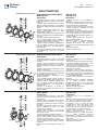
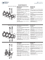
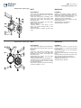
Maintenance valves type:
BVKA-BLKA BVKX-BLKX DN 200-300
DN 125-250
DISASSEMBLY
ASSEMBLY
-Cut out the line upstream and downstream of -Replace O-ring 2 and,if necessary,bushing 3.
the valve to be repaired and make sure there -Insert a guide shaft (the same diameter as
is no pressure.
shaft 4) into the lower hole of the body so
-Close the valve almost completely, then that it extends 15/20 mm from the bushing
loosen and remove the stay bolts. With plane (the extending part of the shaft must be
appropriate tools, widen the flanges and chamfered like the end of shaft 4).
remove the valve.
-Insert disc 8 on the extending part of the
-Disassemble the operator (lever with shaft, then push until the opposite hole mates
positioner disc or actuator) from the upper with the through hole of the upper shaft .
flange of the valve body.
-Insert shaft 4 until the holes on it mate with
-Unscrew lower plug 13 and remove flange 6 those on the disc.
by removing screws 7.
-Reassemble screws 11, replacing O-rings 9 if
-Unscrew and remove screws 11 with O-rings necessary. Replace and reassemble plug 13
Manutenzione
tipo BVKA-BLKA DN 200
9 and washersvalvole
10.
and/ 300
O-ring 12.
-With an extractor, removeBVKX-BLKX
upper shaft 4 DN
by 125
-Assemble
/ 200 flange 6.
means of valvole
its threaded
hole. RemoveDN
bushing
-Reassemble the operator.
Manutenzione
tipo BVKA-BLKA
200 / 300
3 and O-ring 2.
BVKX-BLKX DN 125 / 200
-Remove disc 8, using a rubber mallet if
necessary. Be very careful not to damage the
disc profile.
-Because the liner is vulcanised to the valve
Manutenzione
valvole
tipo BVKA-BLKA
DN 200 body
/ 300
body, either
replace
the entire vulcanised
BVKX-BLKX
DN 125 / 200
or send it to GHIBSON
for new vulcanising.
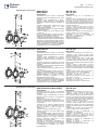
Maintenance valves type:
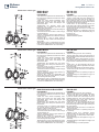
BVKA-BLKA DN 350-500
DISASSEMBLY
ASSEMBLY
-Cut out the line upstream and downstream of -Replace bushings 2 and 13 if necessary.
the valve to be repaired and make sure there -Set the valve body on the press and insert a
is no pressure.
guide shaft (the same diameter as shaft 3) into
-Close the valve almost completely, then the lower hole
loosen and remove the stay bolts. With of the body so that it extends 20/30 mm from
appropriate tools, widen the flanges and the bushing plane (the extending part of the
remove the valve.
shaft must be chamfered like the end of shaf
-Disassemble the operator from the upper t 3).
flange of the valve body and remove key 7 -Insert disc 9 on the extending part of the
from shaft 3.
shaft, then push until the opposite hole mates
-Unscrew screws 16 and 8. Remove lower with the through
flange 15 and upper flange 6.
hole of the upper shaft (use the press piston).
-Unscrew and remove screws 12 with O-rings -Insert shaft 3 until the holes on it mate with
10 and washers 11.
those on the disc.
Manutenzione
valvole
tipo BVKA-BLKA
DN
350
/ 500
Manutenzione
valvole
tipo
BVKA-BLKA
DN 3350
-With an extractor,
remove
upper shaft
by / 500
-Reassemble
screws 12, replacing O-rings 10
means of its threaded hole.
if necessary.
-Remove disc 9 with an appropriate tool -Assemble flange 15 and replace O-ring 14 if
(press with hydraulic piston). Be very careful necessary.
not to damage
the disc
profile. DN 350 / 500 -Assemble flange 6 and replace O-ring
Manutenzione
valvole tipo
BVKA-BLKA
-Because the liner is vulcanised to the valve
body, either replace the entire vulcanised body
or send it to GHIBSON for new vulcanising.
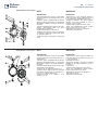
Maintenance valves type:
BVKI-BVKA-BLKI-BLKA-BFKI DN 600-800
DISASSEMBLY
ASSEMBLY
-Cut out the line upstream and downstream of -Replace bushings 2 and 13 if necessary.
the valve to be repaired and make sure there -Set the valve body on the press and insert
is no pressure.
a guide shaft (the same diameter as shaft
-Close the valve almost completely, then 3) into the lower hole of the body so that it
loosen and remove the stay bolts. With extends 20/30 mm from the bushing plane
appropriate tools, widen the flanges and (the extending part of the shaf t must be
remove the valve.
chamfered like the end of shaft 3).
-Disassemble the operator from the upper -Insert disc 9 on the extending part of the
flange of the valve body and remove key 5 shaft, then push until the opposite hole mates
from shaft 3.
with the through hole of the upper shaft (use
-Unscrew screws 19. Remove lower flange the press piston).
Manutenzione
valvole
tipo15BVKI-BVKA-BLKI-BLKA-BFKI
600
/ 800the holes on it mate with
18, unscrew
screws
and unscrew support -Insert DN
shaft
3 until
register 14 with
a hooktipo
spanner.
those on the disc.
Manutenzione
valvole
BVKI-BVKA-BLKI-BLKA-BFKI
DN 600 / 800
-Remove flange 7 by removing screws 8.
-Reassemble screws 11, replacing O-rings 10
Manutenzione
valvole
tipo BVKI-BVKA-BLKI-BLKA-BFKI
DN 600 / 800
-Unscrew
and remove
screws 11 with O-rings if necessary.
10 and washers 12.
-Replace O-ring 16 if necessary. Screw
-With an extractor, remove upper shaft 3 by support register 14 fully down, then unscrew
means of its threaded hole.
it 1/2 turn. Lock it in this position with socket-Remove disc 9 with an appropriate tool head screws 15.
(press with hydraulic piston). Be very careful -Assemble flange 18 and replace O-ring 17 if
not to damage the disc profile.
necessary.
-Because the O-ring is vulcanised to the valve -Assemble flange 7 and replace O-rings 4 and
body, either replace the entire vulcanised body 6 if necessary.
or send it to GHIBSON for new vulcanising.
-Reassemble key 5 and the operator.