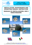
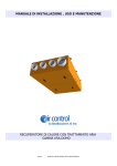
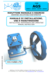
1
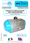
TYPE
ASM512
BOX FINECORSA
LIMIT SWITCHES BOX
Con 2 micro interruttori SPDT / with 2 micro switches SPDT
MANUALE DI INSTALLAZIONE,
USO E MANUTENZIONE
INSTALLATION, MAINTENANCE AND OPERATING
MANUAL INSTRUCTION
II 2 G
BOX FINECORSA
CERTIFICATO S.I.L.2
LIMIT SWITCHE BOX
CERTIFIED S.I.L.2
Ex d IIB T6 IP66 T 85°C
BOX FORNITO NON CABLATO, LE CAMME NECESSITANO DI REGOLAZIONE DOPO CABLATURA
BOX DELIVERED NOT CABLED, CAMS REQUEST REGULATION AFTER CABLED
ADLER SpA – VALVOLE A SFERA
20010 S. STEFANO TICINO (MI) ITALY V.le BORLETTI, 14 Tel. +39/02974842.11 FAX +39/0297271698
E-mail: [email protected] http://www.adlerspa.com
TYPE
ASM512
INDICE / INDEX
1.0
INTRODUZIONE / GENERAL
2.0
ISTRUZIONI PER LA SICUREZZA / WARNING
3.0
CONDIZIONI DI LAVORO E DATI TECNICI / WORKING CONDITIONS AND TECHNICAL DATA
4.0
ISTRUZIONI DI INSTALLAZIONE BOX-FINECORSA / INSTALLATION INSTRUCTION OF BOX-FINECORSA
5.0
ISTRUZIONI DI MANUTENZIONE (SMONTAGGIO E RIMONTAGGIO) / MAINTENANCE INSTRUCTION (DISASSEMBLY AND
ASSEMBLY)
6.0
SCHEMA DI COLLEGAMENTO / WIRING DIAGRAM
7.0
CARATTERISTICHE MICRO-INTERRRUTTORI / MICRO-SWITCHES FEATURES
8.0
STOCCAGGIO A MAGAZZINO / STORAGE
1.0
INTRODUZIONE / GENERAL
Questo manuale d’istruzioni contiene importanti informazioni relative
all’installazione, all’utilizzo, alla manutenzione e allo stoccaggio dei BOX ADLER
ASM512.
Leggere queste istruzioni attentamente e conservarle in caso di necessità.
È importante che l’assemblaggio e il disassemblaggio dei BOX sia effettuato solo
da personale istruito.
2.0
Please read these instructions carefully and save them for future reference.
It’s important that only properly trained personnel disassemble or assemble the
BOX.
ISTRUZIONI PER LA SICUREZZA / WARNING
Per BOX utilizzati in atmosfera potenzialmente esplosiva, assicurarsi che le
parti interne del BOX non vengano mai in contatto con l’atmosfera esterna.
L’utilizzo del BOX al di fuori del range di temperatura previsto può
danneggiare componenti interni ed esterni
L’utilizzo del box in ambiente corrosivo senza adeguate protezioni può
danneggiare componenti interni ed esterni.
Non rimuovere nessun componente quando il box è in funzione.
Prima dell’installazione su una valvola o su un attuatore, assicurarsi che
l’orientamento dell’indicatore di posizione sia corretto.
Se il box è incorporato in un impianto, l’acquirente deve assicurarsi che
vengano rispettate le normative di sicurezza vigenti.
Non toccare il box quando è collegato all’impianto.
Assicurasi che le caratteristiche del collegamento elettrico siano compatibili
con i parametri elettrici di funzionamento del box.
Assicurarsi che il box sia collegato alla messa a terra tramite l’apposita vite.
Verificare la posizione delle cammes prima di mettere in funzione il box.
Assicurarsi che i pressacavi siano ben avvitati per evitare infiltrazioni
all’interno del box.
Assicurarsi che le viti di unione della scatola box e del coperchio siano serrati
a fondo e che l’Oring di tenuta sia in posizione corretta.
Assicurarsi che i cavi elettrici siano ben serrati e completamente inseriti
all’interno della morsettiera ed evitare che ci sia del materiale conduttore non
isolato.
Rispettare lo schema di collegameto dei cavi elettrici come indicato sulla parte
interna del coperchio e riportato al paragrafo 6 del presente documento.
In caso di rimozione dell’indicatore esterno, assicurasi che l’Oring di tenuta sia
posizionato correttamente.
3.0
This instruction manual contains important informations regarding the installation,
operation, maintenance and storage for the ADLER ASM512 BOX.
For use BOX in potentially explosive atmosphere, make sure that the inside of
the box never come in contact with the outer atmosphere.
The use of the box outside the expected range of temperature can damage
internal or external components.
The use of boxes in corrosive environment without adequate protection can
damage internal or external components.
Do not remove any component when the box is running.
Before installation on a valve or an actuator, make sure that the orientation of
the indicator position is correct.
If the box is built in a plant, the buyer must ensure that you comply with
safety regulations in force.
Do not touch the box when it is connected to the plant.
Ensure that the characteristics of the electrical connections are compatible
with the electrical parameters of operation of the box.
Make sure the box is connected to ground by the screw.
Check the position of the cam before you operate the box.
Make sure the cable are securely screwed to prevent infiltration inside the
box.
Make sure the screws merge box and the lid of the box are tightened and that
the Oring seal is in correct place.
Make sure electrical cords are securely locked and fully inserted into the
terminal and ensure that there aren’t materials non-insulated conductor.
Observe the pattern became interrupted electrical cables as indicated on the
inside of the cover and at paragraph 6 of this document.
In case of removal of the externally, ensure that the Oring seal is positioned
correctly
CONDIZIONI DI LAVORO E DATI TECNICI / WORKING CONDITIONS AND TECHNICAL DATA
Tensione operativa:
AC:250V 15A, 125V 15A.
DC:250V 0.3A, 125V 0.6A.
Temperatura operativa
Il range di temperatura operativa per il box è -20°C < T < +85°C.
Tempi operativi
La velocità di movimento dipende dalla velocità di movimento della valvola o
dell’attuatore su cui è installato il box.
Lubrificazione
Tutte le parti in movimento del box vengono consegnate lubrificate a vita.
Costruzione
Il box ADLER ASM è progettato e costruito per applicazione sia interna che
esterna.
Marcatura
Il tipo di box, la classe di protezione, il tipo di interruttori, il voltaggio utilizzabile
sono indicati sull’attuatore stesso.
Connessioni
Foratura inferiore per accoppiamento su valvola o attuatore, secondo norme ISO
5211/DIN 3337. Doppia foratura filettata M20x1,5. Morsettiera multipla a 8
ingressi.
Collaudo
Ogni singolo box viene testato al momento in cui viene assemblato.
Operating Voltage:
AC: 250V 15A, 125V 15A.
DC: 250V 0.3A, 125V 0.6A.
Operating temperature
The operating temperature range for the box is -20 ° C <T <+80 ° C.
Operating time
The speed of movement depends on the speed of movement of the valve or
actuator is installed on the box.
Lubrication
All moving parts in the boxes are delivered lubricated or life.
Construction
The box ADLER ASM is designed and built for application both internally and
externally.
Marking
The type of box, protection class, the type of switches, the voltage used are
indicated on the actuator itself.
Connections
Drilling lower mating valve or actuator, according to ISO 5211/DIN 3337. Double
drilling threaded M20x1,5. Multipoint terminal strip with 8 input.
Testing
Every single box is tested at the time it is assembled.
ADLER SpA – VALVOLE A SFERA
20010 S. STEFANO TICINO (MI) ITALY V.le BORLETTI, 14 Tel. +39/02974842.11 FAX +39/0297271698
E-mail: [email protected] http://www.adlerspa.com
TYPE
ASM512
ADLER SpA – VALVOLE A SFERA
20010 S. STEFANO TICINO (MI) ITALY V.le BORLETTI, 14 Tel. +39/02974842.11 FAX +39/0297271698
E-mail: [email protected] http://www.adlerspa.com
TYPE
ASM512
4.0
ISTRUZIONI DI INSTALLAZIONE DEL BOX / BOX INSTALLATION INSTRUCTION
Il BOX ADLER ASM512 è un apparecchio elettrico per il controllo remoto di valvole
industriali.
Tutte le informazioni tecniche necessarie per l’installazione corretta e sicura del
BOX sulla valvola o sull’attuatore (voltaggi, schema collegamenti elettrici, tipo di
connessioni, temperatura di utilizzo, grado di protezione) sono chiaramente
indicate nella scheda tecnica del BOX ASM512 e all’interno del presente manuale.
Leggere attentamente le informazioni tecniche seguenti prima di procedere con
l’installazione del BOX.
BOX ADLER ASM512 is an electrical device for remote control of industrial valves.
All the technical information necessary for proper installation and safe box on the
valve or actuator (voltage, wiring diagram, type of connections, operating
temperature, degree of protection) are clearly indicated in the datasheet of BOX
ASM512 and inside of this manual.
Carefully read the following technical information before proceeding with the
installation of the BOX.
IMPORTANTI INFORMAZIONI DI SICUREZZA:
Il BOX non deve essere collegato elettricamente durante l’installazione
Durante la connessione del BOX ASM512con l’impianto di alimentazione elettrica
assicurarsi che la tensione nei fili di collegamento sia assente.
Prima del fissaggio del BOX ASM512 su attuatore o su valvola, accertarsi che
entrambi siano correttamente allineati in funzione del senso di rotazione
richiesto.
IMPORTANT SAFETY INFORMATION:
The BOX must not be electrically connected during installation
When connecting the BOX ASM512 with the electrical supply system to ensure
that the tension in the wire connection is absent.
Before mounting the box ASM512 on the actuator or valve, make sure that both
are correctly aligned according to the direction of rotation required.
CONTROLLI E CONNESSIONI:
Il BOX, sulla faccia inferiore, presenta una foratura a norme ISO 5211 (DIN
3337), per il fissaggio del BOX sulla valvola o sull’attuatore tramite la staffa di
fissaggio.
Il BOX ADLER ASM512 ha due forature 1/2” NPT per la connessione dei pressa
cavi.
La trasmissione del movimento dall’attuatore o della valvola al BOX ASM512
avviene mediante accoppiamento meccanico.
CONTROLS AND CONNECTIONS:
The BOX, on the lower side, has a hole to ISO 5211 (DIN 3337), for attaching the
box on the valve or actuator via bracket.
BOX ADLER ASM512 has two holes 1 / 2 "NPT for connection of the press wires.
The transmission of the movement actuator or valve at the box ASM512 is via
mechanical coupling.
5.0
ISTRUZIONI DI MANUTENZIONE (SMONTAGGIO E RIMONTAGGIO) / MAINTENANCE INSTRUCTION (DISASSEMBLY AND
ASSEMBY)
Tramite le informazioni sotto riportate, Adler S.p.A. fornisce all’utilizzatore finale
tutte le informazioni necessarie per una corretta e sicura manutenzione.
La manutenzione dei BOX Adler S.p.A. è permessa solo al personale Adler S.p.A.
o a personale che sia stato opportunamente istruito.
Ogni inosservanza comporterà il decadimento della garanzia!
Per un buon funzionamento del BOX e per garantirne una lunga durata, si
consiglia un piano di manutenzione da effettuare tra 300.000 e 500.000 manovre
per verificare lo stato di usura di O-Ring di tenuta. In caso di usura avanzata si
procederà alla sostituzione.
Il BOX ASM512 deve essere utilizzato nei limiti stabili dalle caratteristiche del
BOX stesso: in caso di condizioni di utilizzo gravose si consiglia di intensificare le
operazioni di controllo delle condizione degli O-Ring di tenuta e della
manutenzione.
Using the information below, Adler S.p.A. supplies the end user all the information
needed for correct and safety maintenance.
Maintenance BOX Adler S.p.A. is allowed only to staff Adler S.p.A. or staff who has
been properly trained.
Any failure to comply will lead to invalidation of the warranty!
For the smooth running of the BOX and to ensure a long life, we recommend a
maintenance plan to be carried out between 300,000 and 500,000 operations to
check the wear of O-ring seal. When worn will proceed to the advanced
replacement.
BOX ASM512 must be used within the limitations of the characteristics of the box
itself: in case of severe conditions of use should be intensified their control of the
condition of the O-ring sealing and maintenance.
ADLER SpA – VALVOLE A SFERA
20010 S. STEFANO TICINO (MI) ITALY V.le BORLETTI, 14 Tel. +39/02974842.11 FAX +39/0297271698
E-mail: [email protected] http://www.adlerspa.com
TYPE
ASM512
SMONTAGGIO / DISASSENBLY
Eseguire lo smontaggio del box SOLO ED ESCLUSIVAMENTE DOPO AVER
TOLTO LA TENSIONE.
Disconnettere il Box dalla valvola o dall’attuatore e scollegare i cavi elettrici
dalla morsettiera e dalla messa a terra.
Disassembly the box ONLY AFTER THE CURRENT SUPPLY HAS BEEN
INTERRUPTED.
Disconnect the Box from the valve or from the actuator and disconnect the
electric wiring from the multipoint strip terminal and from the grounding.
Rimozione dell’indicatore esterno (21)
Rimuovere le viti TPSC M4x8 (22) e l O-Ring di tenuta (20)
Rimozione dell’indicatore interno (19)
Sollevare l’indicatore (19) senza forzare l’accoppiamento di forma con il
perno (24)
Rimozione del coperchio BOX (15)
Svitare le viti TCCC M6x20 (18) e le rondelle (17)
Tenendo fermo il corpo (4) ruotare e tirare leggermente il coperchio (15)
avendo cura di non deformare il perno dell’indicatore (24)
Outer indicator removal (21)
Remove the screws M4x8 TPSC (22) and the sealing O-Ring (20)
Inner indicator removal (19)
Lift the indicator (19) without forcing the shape matching with the shaft
(24).
Box Cover removal (15)
Remove the screws M6x20 TCCC (18) and the washers (17)
Maintaining fixed the body (4), rotate and pull slightly the cover (15), paying
attention to not deforming the shaft (24)
ATTENZIONE: Durante le fasi di smontaggio, è possibile che l’O-Ring di tenuta
del corpo (23) esca dalla propria sede. È necessario verificare che esso sia nella
propria sede in fase di montaggio, in quanto l’errato posizionamento dell’O-Ring
può provocare malfunzionamenti del Box.
WARNING: During the disassembly, it’s possible that the sealing body O-Ring
(23) come out from its seat. Is necessary to check, during the assembly, that the
O-Ring is in the proper position, since a wrong O-Ring position could involve in a
malfunction of the box.
Rimozione della morsettiera (26)
Rimuovere le viti TCCC M2,5x12 (25).
Rimozione dei micro interruttori (6)
Rimuovere le viti TCCC M2,5x40 (9), le rondelle (8) e i distanziali (7)
Rimozione del perno (24)
Rimuovere l’anello elastico (1) con l’apposita pinza a becchi.
Estrarre il perno (24) facendo attenzione a non danneggiare gli O-Ring (5)
Rimozione della cammes (12) e (14)
Estrarre i perni di fissaggio boccole (10)
Sfilare le boccole rotazione cammes (11), prestando attenzione
all’estensione della molla di fissaggio (13)
Rimuovere le cammes (12) e (14)
Multipoint terminal strip removal (26)
Remove the screws TCCC M2,5x12 (25).
Micro-switches removal (6)
Remove the screws TCCC M2,5x40 (9), the washers (8) and the spacers (7)
Shaft removal (24)
Remove the retaining ring (1) using nap-ring pliers.
Draw the shaft (24) paying attention to not damaging the O-Rings (5)
Cams removal (12) and (14)
Draw the cam bushing pins (10)
Draw the rotational cam bushings (11), paying attention to the cam fixing
spring (13) extent.
Remove the cams (12) and (14)
Dopo lo smontaggio verificare lo stato di usura degli O-Ring di
tenuta (5,20,23), in caso si renda necessario sostituirli.
After removing check the wear of O-Ring (5,20,23), if it becomes necessary to
replace them.
5.1
MONTAGGIO / ASSEMBLY
Assemblaggio delle cammes
Montare la boccola di rotazione cammes (11) e fissarla con il perno di
fissaggio (10), inserire la cammes inferiore (12) e la molla (13).
Inserire la cammes superiore (14) e la seconda boccola (11) e bloccarla con
il perno di fissaggio (10).
FARE ATTENZIONE AL SENSO DI INSERIMENTO DELLE CAMMES (VEDI
SCHEMA SOTTORIPORTATO)
Assemblaggio del perno
Inserire l’ O-Ring (5) nella relativo alloggiamento, inserire il perno (24) nel
corpo del BOX esercitando una leggera pressione.
Inserire l’anello elastico (1).
Assemblaggio della morsettiera
Posizionare la morsettiera (26) in corrispondenza dei fori filettati M2,5 ed
inserire le viti TCCC M2,5x12 (25) ed avvitarle a fondo.
Assemblaggio degli micro-switches
Eseguire il collegamento dei fili elettrici ai micro-interruttori (6) rispettando
posizioni e colori come indicato nello schema di collegamento al paragrafo 6
del presente documento.
Posizionare i distanziali (7) tra i due micro-interruttori (6) ed inserire le viti
TCCC M2,5x40 (9).
Posizionare i micro-interruttore e avvitare le viti TCCC M2,5x40 (9) a fondo
facendo attenzione a non danneggiare le leve dei micro-interruttori.
Collegamento elettrico
Eseguire il collegamento dei fili elettrici alla morsettiera (26) rispettando
posizioni e colori come indicato nello schema di collegamento al paragrafo 6.
Collegamento alla messa a terra
Collegare il filo della messa a terra all’apposita vite (27) munita di rondella
(28) e avvitare a fondo.
Assemblaggio del coperchio BOX
Posizionare O-Ring (23) nella cava ricavata sul coperchio (15).
Avvitare le viti TCCC M6x20 (18) con le rondelle (17) a fondo facendo
attenzione a non danneggiare l’O-Ring di tenuta (23).
Assemblaggio indicatori di posizione
Posizionare l’indicatore interno (19) facendo attenzione che segnali il
corretto stato dell’assieme (aperto o chiuso).
Posizionare l’O-Ring di tenuta (20).
Posizionare l’indicatore esterno (21) facendo attenzione che segnali il
corretto stato dell’assieme e serrare le viti TSPC M4x8 (22) a fondo avendo
cura di non rovinare l’O-Ring di tenuta.
Assembly of the cam
Fit the bush rotation cam (11) and secure with the
locking pin (10), insert the bottom cam (12) and spring (13).
Insert the top cam (14) and the second bushing (11) and lock with the
locking pin (10).
TAKE CARE OF THE WAY OF ENTERING CAMES ( SEE THE FOLLOWING
DIAGRAM)..
Assembly pin
Put the 'O-Ring (5) into the slot, insert the pin (24) into body BOX with light
pressure.
Put the retaining ring (1).
Assembly of terminal strip
Place the terminal strip (626 near the holes threaded M2, 5 screws and
insert TCCC M2, 5x12 (25) and tighten them thoroughly.
Assembly of micro-switches
Connect the wires to the micro-switches (6) positions and colors as shown
in the wiring diagram on paragraph 6 of this document.
Place the spacers (7) between the micro-switches (6) and insert the screws
TCCC M2, 5x40 (9).
Place the micro-switch and tighten the screw TCCC M2,5x40 (9) thoroughly
taking care not to damage the levers of micro-switches.
Electrical connection
Connect the wires to the terminal strip (26) positions and colors as shown in
the wiring diagram on paragraph 6 .
Connection to ground
Connect the grounding wire to the appropriate screw (27) equipped with
washer (28) and tighten.
Assembling the BOX cover
Place O-Ring (23) obtained in the slot on the cover (15).
Tighten the screws M6x20 TCCC (18) with washers (17) thoroughly taking
care not to damage the O-Ring (23).
Assembly locators
Place the internal indicator (19) making sure that the correct state assembly
signals (open or closed).
Place the O-Ring (20).
Place the external indication (21) making sure that signals the proper state
assembly and tighten the screws M4x8 TSPC (22) thoroughly taking care not
to damage the O-rings.
ADLER SpA – VALVOLE A SFERA
20010 S. STEFANO TICINO (MI) ITALY V.le BORLETTI, 14 Tel. +39/02974842.11 FAX +39/0297271698
E-mail: [email protected] http://www.adlerspa.com
TYPE
ASM512
ITEM
N°
Q. TY
DESCRIZIONE
DESCRIPTION
MATERIALE
MATERIAL
2
Anello elastico Seeger Ø 8
Retaining Ring, Ø 8
1.2510 – 100MnCrW4
02
1
Boccola inferiore di rotazione
Rotational Lower Bushing
Bronzo
Bronze
03
1
Tappo filettato
Threaded Plug
AISI 304
AISI 304
04
1
Scatola Box
Box Body
Alluminio pressofuso
DieCasting Aluminium
05
3
O-Ring Stelo, Ø 7x 1,78
Shaft O-Ring, Ø 7 x 1,78
NBR 70 Shore A
NBR 70 Shore A
06
2
Micro - Switch SPDT Meccanico
Mechanical SPDT Micro-switch
\
\
07
4
Distanziale
Spacer
ABS
ABS
08
2
Rondella M2,5
M2,5 Washer
Acciaio Inox A2
A2 Stainless Steel
09
2
Vite TCCC M2,5 x 40
Bolt TCCC M2,5 x 40
Acciaio Inox A2
A2 Stainless Steel
10
2
Perno di fissaggio boccola
Cam bushing pin
Bronzo
Bronze
11
1
Boccola rotazione camme
Rotational cams bushing
ABS
ABS
12
1
Camma inferiore
Bottom Cam
ABS giallo
Yellow ABS
13
1
Molla fissaggio camme
Cam fixing spring
Acciaio Inox AISI302
AISI302 Stainless Steel
14
1
Camma superiore
Top Cam
ABS rosso
Red ABS
15
1
Coperchio Box
Box Cover
Alluminio pressofuso
DieCasting Aluminium
16
1
Boccola superiore di rotazione
Rotational Upper Bushing
Bronzo
Bronze
17
4
Rondella M6
M6 Washer
Acciaio Inox A2
A2 Stainless Steel
18
4
Vite TCCC M6 x 20
Bolt TCCC M6x 20
Acciaio Inox A2
A2 Stainless Steel
19
1
Indicatore interno
Inner indicator
ABS rosso - verde
Red - green ABS
20
1
O-ring Cupola indicatore
O-ring Indicator Dome
NBR 70 Shore A
NBR 70 Shore A
21
1
Indicatore esterno
Outer indicator
Policarbonato
Polycarbonate
22
4
Vite TSPC M4 x 8
Bolt TSPC M4 x 8
Acciaio Inox A2
A2 Stainless Steel
23
1
Guarnizione coperchio
Cover O-Ring
NBR 70 Shore A
NBR 70 Shore A
24
4
Perno
Shaft
Acciaio Inox AISI420
AISI420 Stainless Steel
25
2
Vite TCCC M2,5 x 12
Bolt TCCC M2,5 x 12
Acciaio Inox A2
A2 Stainless Steel
26
1
Morsettiera Multipla a 8 vie
8 Ways Multipoint Terminal Strip
PA 6,6 30% GFR +
TBBPA (flame retarder)
27
1
Vite TSPC M4 x 10 (Terra)
Bolt TSPC M4 x 10 (Ground)
Acciaio Inox A2
A2 Stainless Steel
28
1
Rondella M4
M4 Washer
Acciaio Inox A2
A2 Stainless Steel
29
1
Tappo filettato
Threaded Plug
PP giallo
Yellow PP
30
1
O-Ring tappo filettato
Threaded plug O-Ring
NBR 70 Shore A
NBR 70 Shore A
01
ADLER SpA – VALVOLE A SFERA
20010 S. STEFANO TICINO (MI) ITALY V.le BORLETTI, 14 Tel. +39/02974842.11 FAX +39/0297271698
E-mail: [email protected] http://www.adlerspa.com
TYPE
ASM512
SCHEMA DI INSERIMENTO BOCCOLE E CAMMES
WIRING OF ENTERING OF BUSHING AND CAMS
Le cammes devono essere inserite nella posizione corretta
all’interno dell’albero (24) per permettere la trasmissione del
moto rotatorio tra l’albero e le stesse cammes, il cui
posizionamento deve far riferimento alla figura qui indicata
(dentatura verso l’alto per la camma superiore rossa (14) e
dentatura verso il basso per la camma inferiore gialla (12).
Precedentemente al posizionamento delle camme, tra le 2
superfici piane delle 2 deve essere stata inserita la molla di
contrasto (13)
Le boccole zigrinate (11) devono essere inserite esternamente
alla cammes, in modo da avere l’accoppiamento tra la dentatura
esterna della boccola e quella interna della camma. Tale
dentatura permette la regolazione della posizione relativa delle
cammes rispetto alla rotazione albero, e quindi l’angolo di
azionamento dei micro-switches, con incrementi di regolazione
pari a 10°
Le boccole zigrinate (11) devono essere rese solidali con la
rotazione dell’albero (24) mediante i perni (10)
The cams should be assembled properly onto the shaft (24)
axle, to avoid the movement transmission between the shaft
and the cams themselves.
The cams position should be referred to the diagram here shown
(gears on the upper surface for the top red cam (14) and gears
on the lower surface for the bottom yellow cam (12)).
Before the cams positioning, the contrast spring should be
inserted between the 2 flat surfaces of the cams.
The knurled bushings (11) should be assembled externally
respect to the cams, so that is achieved a linkage between the
bushing knurling(on the external surface) and the cam knurling
(on the internal surface). The knurling teeth allow the position
adjustment between the cams and the shaft rotation, therefore
the micro-switches range activation, with adjustment steps of
10°.
The knurled bushings (11) should be fixed with the shaft (24)
rotation by the pins (10)
6.0
SCHEMA DI COLLEGAMENTO / WIRING DIAGRAM
ADLER SpA – VALVOLE A SFERA
20010 S. STEFANO TICINO (MI) ITALY V.le BORLETTI, 14 Tel. +39/02974842.11 FAX +39/0297271698
E-mail: [email protected] http://www.adlerspa.com
TYPE
ASM512
7.0
CARATTERISTICHE DEL MICRO-INTERRUTTORE / MICRO-SWITCHES FEATURES
Condizioni operative:
16-20A 250 VAC
Temperature operative:
-20°C / +125°C
Operazioni elettriche minime:
50.000 cicli.
Operazioni meccaniche minime:
1.000.000 cicli.
Standard applicabili:
UL/CAS - ENEC
Caratteristiche di collegamento:
Micro-interruttore SPDT.
Dimensioni del micro-interruttore:
Vedi schema sotto riportato.
Materiale del micro-interruttore:
Plastico.
Marcatura del micro-interruttore:
Fabbricante, numero di matricola, modello e marcatura CE posta
direttamente sul micro-interruttore.
8.0
Operating conditions:
16-20A 250 VAC
Operating temperature:
-20°C / +125°C
Operations Electrical minimum:
50,000 cycles.
Mechanical operations minimum:
1,000,000 cycles.
Applicable Standards:
UL/CAS - ENEC
Product link:
SPDT micro-switch.
Dimensions of the micro-switch:
See diagram below.
Material from the micro-switch:
Plastic.
Identification of the micro-switch:
Manufacturer, serial number, model and CE marking placed directly on the
micro-switch
STOCCAGGIO A MAGAZZINO / STORAGE
Se per il BOX non è previsto un immediato utilizzo, prevedere le seguenti
precauzioni:
Immagazzinare il BOX in in luogo asciutto e temperatura ambiente.
Non rimuovere i tappi di plastica.
Eseguire delle rotazioni per evitare l’incollaggio delle guarnizioni di tenuta o
deformazioni permanenti delle guarnizioni.
Al momento della messa in servizio assicurarsi che all’interno non si sia
formata umidità.
Al momento della messa in servizio verificare che i fili del collegamento
elettrico siano ancora bloccati sia dentro il micro-interruttore che nella
morsettiera.
If the BOX is not for immediate use, provide the following precautions:
Store the box in a dry place and at room temperature.
Do not remove the plastic plugs.
Perform the rotation to prevent sticking of the seals or permanent
deformation of the gasket.
When commissioning ensure that moisture has formed inside it.
When commissioning check that the wires electrical connection are still stuck
inside the micro-switch in the terminal strip.
ADLER SpA – VALVOLE A SFERA
20010 S. STEFANO TICINO (MI) ITALY V.le BORLETTI, 14 Tel. +39/02974842.11 FAX +39/0297271698
E-mail: [email protected] http://www.adlerspa.com