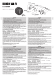
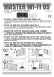
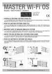
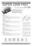
1
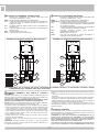
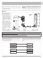
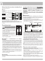
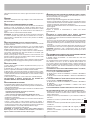
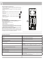
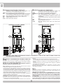
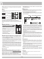
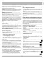
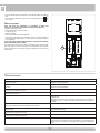
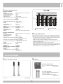
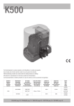
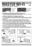
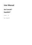
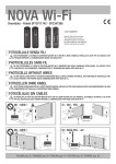
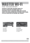
NOVA Wi-Fi
Brevettato - Patent EP10711742 - EP2347398
code ACG8037
Batterie alcaline AA non incluse
Piles alcalines AA non incluses
AA Alkaline batteries not included
AA Akaline-Batterien nicht beiliegend
Baterías alcalinas AA no incluidas
I
FOTOCELLULE SENZA FILI
F
PHOTOCELLULES SANS FIL
G
B
NON POSIZIONARE LA SCHEDA DI GESTIONE MASTER Wi-Fi DIETRO A MURI, PANNELLI METALLICI O ALTRI TIPI DI
OSTACOLI CHE POSSANO IMPEDIRE LA COMUNICAZIONE RADIO CON NOVA Wi-Fi
NE PAS POSITIONNEZ LA FICHE DE GESTION MASTER Wi-Fi DERRIÈRE DES MURS, PANNEAUX MÉTALLIQUES, OU
AUTRES TYPES D’OBSTACLES QUI POURRAIENT COMPROMETTRE LA TRANSMISSION RADIO AVEC NOVA Wi-Fi.
PHOTOCELLS WITHOUT WIRES
DO NOT INSTALL MASTER Wi-Fi RECEIVER CARD BEHIND WALLS, METAL FRAMES OR PANELS, OR OTHER KIND
OF OBSTACLES THAT COULD PREVENT THE PROPER RADIO COMMUNICATION WITH NOVA Wi-Fi.
D
FOTOZELLEN OHNE KABEL
E
S
FOTOCÉLULAS SIN CABLES
NICHT INSTALLIEREN MASTER Wi-Fi KARTE HINTER MAUERN, METALLPLATTEN ODER ANDERE ARTEN VON
HINDERNISSEN, DIE DEN FUNKVERKEHR MIT NOVA Wi-Fi BEEINTRÄCHTIGEN KÖNNEN.
NO INSTALAR LA FICHA DE GESTION MASTER Wi-Fi EN UN LUGAR DETRÁS DE LAS PAREDES, DE PANELES DE
METAL O DE OTRO TIPO DE OBSTÁCULOS QUE PUEDAN IMPEDIR LA COMUNICACIÓN POR RADIO CON NOVA Wi-Fi
NO - NEIN !
SI - OUI - YES - JA !
MASTER Wi-Fi
MASTER Wi-Fi
NO - NEIN !
SI - OUI - YES - JA !
MASTER Wi-Fi
MASTER Wi-Fi
ITALIANO pag. 02 / ENGLISH page 08
I
SETTAGGI E COLLEGAMENTI TRASMETTITORE
SETTAGGI E COLLEGAMENTI RICEVITORE
J6
orsetti per collegamento del contatto pulito della costa
M
meccanica o resistiva (N.C. o N.O.)
SWTX Microinterruttori di abbinamento e identificazione
JP3
Ponticello abilitazione/esclusione costa (di serie ponticello non
inserito per costa non collegata. Chiudere il ponticello se si
collega una costa)
JP4
Ponticello selezione contatto costa N.O./N.C. (impostazione di
fabbrica N.C.)
JP5
Ponticello selezione range di portata 13/25 m (impostazione di
fabbrica 25 M)
BAT
Batterie alcaline 2 x AA 1,5V
DLTX Led verde per verifica funzionamento
J7
orsetti per collegamento del contatto pulito della costa
M
meccanica o resistiva (N.C. o N.O.)
SWRX
Microinterruttori di abbinamento e identificazione
S3 PROG. TX Pulsante per memorizzazione e allineamento
JP6
Ponticello abilitazione/esclusione costa (di serie ponticello
non inserito per costa non collegata. Chiudere il ponticello
se si collega una costa)
JP7
Ponticello a filo selezione funzionamento come fotocellula
o costa (impostazione di fabbrica CHIUSO)
JP8
P onticello selezione contatto costa N.O./N.C.
(impostazione di fabbrica N.C.)
BAT
Batterie alcaline 2 x AA 1,5V
DLRX
Led rosso per segnalare la corretta alimentazione e
l’allineamento del segnale infrarosso
SCHEMA CON POSIZIONI STANDARD DEI PONTICELLI
SCHEMA CON POSIZIONI STANDARD DEI PONTICELLI
BAT
BAT
DLRX
DLTX
JP7
JP5
SWTX
JP3
J6
JP6
JP8
JP4
SWRX
J7
S3
NOTA: O
GNI VOLTA CHE SI ESEGUE UNA NUOVA CONFIGURAZIONE TRAMITE PONTICELLO E’ NECESSARIO TOGLIERE E RIDARE
ALIMENTAZIONE SIA AL TRASMETTITORE CHE AL RICEVITORE.
RIFERIMENTI
AUTOMATICI
NORMATIVI
PER
PORTE
E
L’installatore del dispositivo di sicurezza deve fornire all’utilizzatore finale quanto
segue:
- i dispositivi di sicurezza devono essere fatti conoscere a tutte le persone
appropriate.
- le aree che danno accesso ai dispositivi devono essere tenute libere da ostacoli;
- i requisiti per la pulizia per evitare eventuali accumuli pericolosi di materiale;
- possibili dettagli per una procedura di riavvio da eseguire dopo una fermata di
emergenza o accidentale causata dal sistema di controllo.
La modifica del progetto o della configurazione dell’apparato senza la
consultazione del fabbricante o del suo rappresentante autorizzato può creare
situazioni pericolose.
CANCELLI
L’installatore deve assicurarsi che l’installazione delle fotocellule NOVA Wi-Fi sia
fatta solo in presenza di una ulteriore protezione principale come specificato nella
norma EN12453 al punto 5.5.1. (requisiti generali di protezione).
RIB NON PUÓ CONSIDERARSI RESPONSABILE PER EVENTUALI DANNI
CAUSATI DA UN USO IMPROPRIO, ERRONEO O IRRAGIONEVOLE.
Restrizioni d’uso: Le fotocellule NOVA Wi-Fi non possono essere utilizzate su
apparecchiature escluse dall’applicazione della EN12978, quali:
- apparati di protezione per installazione su porte destinate ad un uso differente
rispetto a quello sulle porte di accessi pedonali e veicolari coperti dalla norma
e il cui principale uso è quello di dare accesso sicuro in luoghi industriali,
commerciali, pubblici o residenziali. Alcuni esempi di esclusioni possono essere:
chiuse e paratie; porte di ascensori; porte di veicoli; porte principalmente usate
per la custodia di animali; tende in tessuto per teatro; barriere ferroviarie;
barriere utilizzate solo per veicoli.
- dispositivi usati solo per il controllo normale e per l’arresto, incluso l’arresto di
emergenza, di porte motorizzate.
- apparati di sicurezza o dispositivi di sicurezza per l’uso su macchine diverse
dalle porte.
ATTENZIONE: Eventuali modifiche del prodotto o della configurazione
dell’apparato non possono essere eseguite senza consultare il fabbricante o il
suo rappresentante autorizzato.
POSSIBILITÁ DI IMPIEGO
Le fotocellule NOVA Wi-Fi comunicano costantemente ed esclusivamente con la
scheda MASTER Wi-Fi e soddisfano completamente i requisiti di una sicurezza
attiva su tutti i tipi di aperture automatiche.
ATTENZIONE: Se viene tolta l’alimentazione del MASTER Wi-Fi per un
periodo di tempo prolungato le coste TOUCH Wi-Fi e le fotocellule NOVA
Wi-Fi esauriranno più velocemente del normale la carica delle loro batterie.
Tenere i MASTER Wi-Fi sempre correttamente alimentati per garantire la
durata di 3 anni delle batterie come dichiarata da RIB.
Se per esempio viene tolta la tensione al cancello tutte le notti, fotocellule e
coste “cercano” ripetutamente il segnale dal MASTER Wi-Fi senza trovarlo
2
I
e quindi la durata delle batterie di questi accessori si riduce a meno di un
anno.
GRAZIE ALLA FUNZIONE SLEEP MODE, A PORTA FERMA LE FOTOCELLULE
SONO SPENTE CONSENTENDO UN RISPARMIO ENERGETICO DELLE
BATTERIE.
Sono prodotte nella versione da parete, da fissare su colonne in ferro o di altro
materiale liscio, o su COLONNINE DI SUPPORTO DEDICATE cod. ACG8039.
LE FOTOCELLULE NOVA Wi-Fi SONO ACCESE SOLO DURANTE
L’AZIONAMENTO DELLA PORTA.
MONTAGGIO
N.B.: Prima di posizionare o
incollare la dima di foratura (cod.
CVA1940) controllare che la
superficie di contatto sia pulita.
- Fissare le basi plastiche CPL1312
sui pilastri o sulle colonnine ad
un’altezza di circa 40÷60 cm dal
suolo e ad una distanza max di 10
cm dalla zona di convogliamento
o schiacciamento o subito dopo
l’ingombro dato da un’eventuale
costa.
- Terminare le regolazioni montare
lo schermo protettivo CPL1311.
- Installare il ricevitore NOVA
Wi-Fi al massimo a 20 metri di
distanza dalla scheda MASTER
Wi-Fi per consentire il corretto
funzionamento radio e in ombra o
in una posizione in cui il sole non
possa battere orizzontalmente
per consentire il corretto
funzionamento del segnale
infrarosso.
BC08037R
- In ogni caso si consiglia di
CPL1311
CPL1312
CPL1940
BC08037T
posizionare le fotocellule alla
stessa altezza e allineate tra loro.
- Per il corretto posizionamento delle fotocellule fare riferimento al manuale di installazione dell’operatore o comunque alla norma EN12445.
IMPORTANTE!
POSIZIONARE IL RICEVITORE DELLA FOTOCELLULA IN VISTA DELLA SCHEDA MASTER Wi-Fi. TRA MASTER Wi-Fi E RICEVITORE NOVA Wi-Fi NON
DEVONO ESSERCI OSTACOLI IN METALLO O IN CEMENTO.
Se non è possibile posizionare il Ricevitore NOVA Wi-Fi in vista della scheda MASTER Wi-Fi per la presenza di ostacoli, installare un’antenna 868 MHz
(cod. ACG5451) a MASTER Wi-Fi in modo da garantire la buona qualità delle trasmissioni radio.
Questi accorgimenti evitano che le batterie del Ricevitore NOVA Wi-Fi si scarichino velocemente.
Le fotocellule NOVA Wi-Fi possono essere installate vicinissime tra di loro
grazie alla funzione di SINCRONISMO.
Il SINCRONISMO è garantito per 2 coppie di fotocellule con microinterruttori
1 ON (1a coppia) e 2 ON (2a coppia).
Eventuali altre 2 coppie di fotocellule possono essere installate, ma
invertite nella loro trasmissione/ricezione rispetto alle 2 coppie precedenti.
Devono essere settate con microinterruttori 3 ON (3a coppia) e 4 ON (4a
coppia).
TX PHOT 1
RX PHOT 1
TX PHOT 2
RX PHOT 2
RX PHOT 3
TX PHOT 3
RX PHOT 4
TX PHOT 4
3
I
NOTA: E’ possibile collegare sia al ricevitore che al trasmettitore delle coste
meccaniche o resistive come riferito nel paragrafo “COLLEGAMENTO DI COSTE
MECCANICHE O RESISTIVE”.
Ogni coppia di fotocellule NOVA Wi-Fi deve essere OBBLIGATORIAMENTE
univocamente identificata mettendo su ON un solo diverso microinterruttore
dei 6 presenti sulla scheda. Esempio: Impostare DIP 1 ON su MASTER Wi-Fi, DIP
1 ON su ricevitore NOVA Wi-Fi e DIP 1 ON su trasmettitore NOVA Wi-Fi.
IDENTIFICARE I CONTENITORI DELLE FOTOCELLULE NOVA Wi-Fi
APPLICANDO L’ADESIVO IN DOTAZIONE ALL’ESTERNO DI OGNI
CONTENITORE.
L’IDENTIFICAZIONE SERVE PERCHE’ POSSA ESSERE VELOCEMENTE
IDENTIFICATA LA FOTOCELLULA QUANDO LE SUE BATTERIE SONO
QUASI SCARICHE.
PORTATA
È possibile decidere la portata delle fotocellule posizionando un jumper sul/sui
trasmettitore/i.
Ponticello JP5 con portata regolata a 13 m
JP5
MEMORIZZAZIONE
Ponticello JP5 con portata regolata a 25 m (impostazione di fabbrica)
Dopo avere eseguito l’allineamento e l’identificazione delle fotocellule NOVA
Wi-Fi, settare i microinterruttori sulla scheda MASTER Wi-Fi per abilitare le
fotocellule da memorizzare (questa operazione può essere eseguita anche dopo
la procedura di memorizzazione).
Per eseguire la memorizzazione seguire la seguente procedura:
- Premere il tasto PROG RX che si trova sulla scheda MASTER Wi-Fi=> il led
bicolore EDGE PHOT 1 rimarrà acceso rosso lampeggiante per 1 minuto (tempo
utile per eseguire la memorizzazione).
JP5
Con JP5 con portata regolata a 13 m le batterie possono durare più di 4 anni.
Con JP5 con portata regolata a 25 m le batterie durano 3 anni.
Queste durate sono previste con 20 manovre al giorno per tutto l’anno.
Dopo aver fissato le basi plastiche delle fotocellule NOVA Wi-Fi, inserire le schede
elettroniche nelle apposite sedi predisposte sulle basi e quindi fissarle con le viti
in dotazione.
PROG RX
LED BICOLORE EDGE PHOT
COLLEGAMENTO BATTERIE
- Inserire le due batterie alcaline tipo AA da 1,5V
facendo attenzione alle polarità (si veda immagine
a lato).
- Nel momento dell’inserimento delle batterie sul
trasmettitore TX NOVA Wi-Fi il led verde si accende
per 10 secondi segnalando il corretto funzionamento.
In seguito il led si spegne per non consumare
inutilmente l’energia delle batterie, ma la trasmissione
del segnale infrarosso è attiva.
- Nel momento dell’inserimento delle batterie sul
ricevitore RX NOVA Wi-Fi il led rosso si accende per
3 secondi segnalando il corretto funzionamento.
- Se il led rosso rimane acceso le fotocellule sono già
correttamente allineate.
- Se il led rosso si spegne, eseguire l’allineamento del segnale infrarosso come
descritto nel paragrafo successivo.
ALLINEAMENTO
INFRAROSSO
E
SINCRONIZZAZIONE
DEL
24V ac/dc
- Premere il tasto PROG TX sul ricevitore con microinterruttore 1 su ON => sul
MASTER Wi-Fi il led bicolore EDGE PHOT 1 da rosso lampeggiante diventa
verde e un tono di buzzer segnala la corretta memorizzazione della fotocellula.
Contemporaneamente si accende lampeggiante rosso il led bicolore EDGE
PHOT 2 per 1 minuto (tempo utile per eseguire la memorizzazione).
Se non vengono memorizzate altre fotocellule lasciare trascorrere un minuto
oppure premere il tasto PROG. RX per 4 volte per terminare la procedura di
memorizzazione (il led EDGE PHOT 2 si spegnerà) => tutti i led EDGE PHOT
devono risultare spenti durante il funzionamento normale.
PER MEMORIZZARE ALTRE FOTOCELLULE NOVA Wi-Fi:
- Premere il tasto PROG. TX sulla fotocellula con microinterruttore 2 su ON =>
sul MASTER Wi-Fi il led bicolore EDGE PHOT 2 da rosso lampeggiante diventa
verde e un tono di buzzer segnala la corretta memorizzazione della fotocellula.
- Eseguire la stessa procedura per eventuali altre fotocellule (fino ad un massimo
di 4).
NOTA: a fine procedura di memorizzazione e dopo aver abilitato i microinterruttori
switch riferiti alle sicurezze memorizzate sul MASTER Wi-Fi, eseguire una
scansione dei led bicolore EDGE PHOT premendo per 6 volte il tasto PROG. RX.
SEGNALE
- Le fotocellule NOVA Wi-Fi vengono confezionate con allineamento centrale,
tuttavia in caso di necessità è possibile eseguire una regolazione dei gruppi ottici
del trasmettitore e del ricevitore (+90°/-90° in orizzontale e +5°/-5° in verticale).
- Premere il tasto S3 PROG. TX presente sul Ricevitore NOVA Wi-Fi per attivarlo
per 3 minuti (tempo necessario ad eseguire l’allineamento fra trasmettitore
e ricevitore). ATTENZIONE: Trascorsi 3 minuti il led rosso si spegne per non
consumare inutilmente l’energia delle batterie, tuttavia è possibile rinnovare il
tempo di altri 3 minuti semplicemente ripremendo il tasto S3 PROG. TX.
- Ad allineamento eseguito il led rosso presente sul Ricevitore NOVA Wi-Fi si deve
accendere fisso indicando la corretta ricezione del segnale infrarosso ricevuto
dal Trasmettitore NOVA Wi-Fi. Se il led rosso lampeggia, ciò significa che il
segnale risulta debole e quindi l’allineamento è da migliorare fino a quando il led
rosso resta acceso fisso.
- Se il trasmettitore ed il ricevitore sono montati ad una distanza inferiore a 13
metri, consigliamo di posizionare il ponticello JP5 come indicato nel paragrafo
“PORTATA” in questo modo si ha un minor consumo delle batterie con
conseguente allungamento della vita delle stesse.
- Montare lo schermo protettivo.
VERIFICA DEL CORRETTO FUNZIONAMENTO
Terminata la procedura di memorizzazione, verificare il corretto funzionamento tra
Fotocellule NOVA Wi-Fi e MASTER Wi-Fi nel seguente modo:
- Premere il tasto S3 PROG. TX presente su un RX NOVA Wi-Fi per attivarne il
led rosso per 3 minuti.
- Verificare che interponendo un ostacolo il led rosso si spenga e che
contemporaneamente sulla scheda MASTER Wi-Fi il corrispondente led EDGE
PHOT si accenda di colore verde per la durata dell’interposizione.
Anche il led DL3 del MASTER Wi-Fi si deve spegnere per segnalare
l’avvenuto corretto scambio del contatto dedicato all’ingresso PHOT sulla
centralina comando motore.
Ripetere la verifica sulle altre fotocellule NOVA Wi-Fi installate.
Eseguire poi una verifica funzionale di tutte le fotocellule installate attivando la
movimentazione dell’automazione e controllando che interponendo un ostacolo
IDENTIFICAZIONE
Ogni coppia di fotocellule NOVA Wi-Fi viene fornita con i microinterruttori in
posizione OFF per evitare il consumo delle batterie quando non viene utilizzata
(se collegate).
4
I
AGGIUNTA DI ALTRE FOTOCELLULE NOVA Wi-Fi (MAX 6 TOTALI)
l’automazione fermi/inverta se in chiusura, oppure fermi/continui ad aprire se in
apertura.
Se dopo l’installazione si decidono di applicare altre fotocellule per aumentare lo
stato di sicurezza della porta, si consiglia di:
- Togliere tensione alla porta.
- Fissare la coppia di fotocellule aggiuntiva nella posizione desiderata.
- Eseguire la programmazione posizionando su ON un microinterruttore diverso
da quello delle altre fotocellule o sicurezze installate e identificarla con l’adesivo
numerato corrispondente (vedi paragrafo “Identificazione”).
- Abilitare sulla scheda MASTER Wi-Fi il microinterruttore relativo alla fotocellula
appena aggiunta.
- Dare tensione alla porta.
Eseguire le procedure di memorizzazione e verifica come indicato
precedentemente.
ANTENNA
L’antenna di comunicazione radio è già collegata su tutti i ricevitori NOVA Wi-Fi.
NON TOCCATELA !!!
VERIFICA DELLA SEGNALAZIONE DI ALLARME
Verificare che staccando una batteria dal ricevitore fotocellula con microinterruttore
(esempio 3 su ON), ed eseguendo un comando di apertura della porta, su
MASTER Wi-Fi si accenda alternativamente verde/rosso il led bicolore 3, mentre
i led DL2 e DL3 si spengono, e che il buzzer emetta un suono alternato per 1
minuto.
Ripetere la verifica su eventuali altre fotocellule installate.
ATTENZIONE: se togliendo la batteria dal ricevitore fotocellula ed eseguendo
un comando di apertura della porta il buzzer su MASTER Wi-Fi non suona, il
microinterruttore 3 su MASTER Wi-Fi si trova su OFF (consenso non abilitato).
Posizionarlo su ON.
PROCEDURA
DI CANCELLAZIONE DELLA SINGOLA SICUREZZA
(FOTOCELLULA O COSTA) IN CASO DI GUASTO O SOSTITUZIONE
Per cancellare una singola sicurezza memorizzata su MASTER Wi-Fi, procedere
nel seguente modo:
- Premere una o più volte il tasto PROG. RX per selezionare il led bicolore EDGE
PHOT, che lampeggia di color verde, corrispondente alla sicurezza da eliminare.
- Selezionata la sicurezza, premere e mantenere premuto il tasto PROG. RX per
10 secondi.
- Al termine dei 10 secondi il led bicolore EDGE PHOT lampeggia per 6 volte
alternativamente di colore rosso e verde, segnalando l’avvenuta cancellazione.
ATTENZIONE: Posizionare in OFF il microinterruttore relativo alla sicurezza
eliminata, poi eseguire una scansione dei led bicolore premendo per 6 volte il
tasto PROG. RX.
STATO DI ATTENZIONE (avviso di sostituzione batterie)
Lo stato di attenzione (WARNING) avverte l’utilizzatore dell’imminente necessità
di sostituire le batterie.
Quando le batterie quasi scariche raggiungono i 2,3V, la fotocellula ricevitore
segnala via radio a MASTER Wi-Fi lo stato di batteria quasi scarica e attiva il
BUZZER di MASTER Wi-Fi con un tono ogni 3 secondi per 1 minuto.
Lo stato di attenzione si rinnova per 1 minuto a fronte di un comando della porta.
Il led bicolore su MASTER Wi-Fi riferito alla fotocellula con le batterie quasi
scariche, si accende fisso di colore rosso.
Durante queste segnalazioni lo stato del sistema è ancora funzionante, ma è
opportuno sostituire al più presto le batterie evitando il blocco funzionale della
porta che avviene al raggiungimento dei 2,0 V.
Il lampeggiatore SPARK Wi-Fi durante lo stato di attenzione cambia la modalità
di lampeggio eseguendo 2 lampeggi ravvicinati seguiti da 2 secondi di pausa.
COLLEGAMENTO DEL CONTATTO PULITO DI COSTE MECCANICHE
O RESISTIVE ALLE FOTOCELLULE NOVA Wi-Fi
E’ possibile collegare ai trasmettitori e ai ricevitori NOVA Wi-Fi delle coste
meccaniche o resistive.
Per i collegamenti delle coste al trasmettitore o ricevitore della fotocellula NOVA
Wi-Fi, utilizzare un cavo da 2 x 0,5 mm2 con diametro esterno massimo di 5
mm. Nel caso si utilizzi un cavo di diametro inferiore, è opportuno verificare che
il passacavo garantisca la NON infiltrazione di acqua, pertanto per mantenere
il grado di protezione IP44 chiudere ermeticamente con silicone le eventuali
aperture intorno al cavo.
LA FUNZIONALITA’ DELLA COSTA CAMBIA IN BASE A DOVE E’ COLLEGATA,
PERTANTO FARE ATTENZIONE A QUANTO SEGUE:
La costa collegata al RICEVITORE NOVA Wi-Fi:
- se attivata mentre il cancello sta CHIUDENDO => INVERTE IL MOVIMENTO
IN APERTURA;
- se attivata mentre il cancello sta APRENDO => INVERTE IL MOVIMENTO IN
CHIUSURA.
IL SUO FUNZIONAMENTO E’ QUINDI QUELLO INDICATO PER UNA COSTA.
La costa collegata al TRASMETTITORE NOVA Wi-Fi: - se attivata mentre il cancello sta CHIUDENDO => INVERTE IL MOVIMENTO
IN APERTURA;
- se attivata mentre il cancello sta APRENDO => FERMA E POI LASCIA
CONTINUARE L’APERTURA.
IL SUO FUNZIONAMENTO E’ QUINDI COME QUELLO DI UNA FOTOCELLULA.
PER COSTE MECCANICHE TOUCH (cod. ACG3015) CON CONTATTO N.C.
- Collegare in serie al contatto N.C. della costa una resistenza da 8,2 KΩ (senza
tale resistenza il sistema non funziona ed entra in allarme - vedere tabella “IN
CASO DI DIFFICOLTA’)
- Collegare ai morsetti J6 per il trasmettitore o J7 per il ricevitore il contatto N.C.
della costa.
STATO DI ALLARME
Lo stato di allarme si attiva con batterie completamente scariche (2,0 V) o con
guasto della fotocellula.
Su MASTER Wi-Fi i led DL2 e DL3 si spengono bloccando l’automazione in
quanto non è garantita la funzionalità di una delle fotocellule installate.
Su MASTER Wi-Fi il led riferito alla fotocellula con batterie scariche o guasta,
lampeggia alternativamente rosso/verde ed il buzzer emette un tono alternato per
1 minuto richiamando l’attenzione dell’utilizzatore che dovrà sostituire le batterie
o riparare la fotocellula.
Lo stato di allarme si rinnova per 1 minuto a fronte di un comando della porta.
PER ESCLUDERE LA SINGOLA FOTOCELLULA DAL SISTEMA Wi-Fi
LEGGERE IL MANUALE DELLA SCHEDA MASTER Wi-Fi.
SOSTITUZIONE DELLE BATTERIE
La durata delle batterie applicate alle fotocellule NOVA Wi-Fi è di circa 3 anni.
- Identificare quale fotocellula ha le batterie scariche guardando i led EDGE-PHOT
sulla scheda MASTER Wi-Fi.
- Identificare tramite il numero della coppia di fotocellule con le batterie scariche
a lato del led bicolore che:
- lampeggia alternativamente rosso/verde (se in allarme)
- acceso rosso fisso (se in attenzione)
- acceso verde fisso (se batteria trasmettitore NOVA Wi-Fi scarica)
- Ricercare sul contenitore delle fotocellule installate l’adesivo con il numero di
identificazione corrispondente.
- Sostituire le batterie sia sul trasmettitore che sul ricevitore facendo attenzione
al rispetto delle polarità.
- Premere il tastino PROG TX della fotocellula ricevitore per riattivare il
funzionamento di MASTER Wi-Fi. Il buzzer a bordo della scheda MASTER Wi-Fi
se attivo si spegne e i led DL2- DL3 (se in allarme) si accendono e il led bicolore
riferito alla fotocellula a cui sono state sostituite le batterie si spegne.
L’automazione è pronta a ripartire in tutta sicurezza.
ATTENZIONE: Vi ricordiamo che le batterie vanno smaltite secondo le
Norme vigenti. In caso di rottamazione delle fotocellule vi ricordiamo di
togliere le batterie e di smaltirle secondo le Norme vigenti.
JP6
- Posizionare sul ricevitore il ponticello JP6 nella seguente posizione per
abilitare la costa:
- Posizionare sul ricevitore il ponticello JP8 nella seguente posizione per gestire
JP8
il contatto N.C.:
- Posizionare sul trasmettitore il ponticello JP3 nella seguente posizione per
abilitare la costa:
JP3
- Posizionare sul trasmettitore il ponticello JP4 nella seguente posizione per
gestire il contatto N.C.:
JP4
5
I
PER COSTE RESISTIVE CON CONTATTO N.O.
- Collegare in parallelo al contatto N.O. della costa una resistenza da 8,2 KΩ
(senza tale resistenza il sistema non funziona ed entra in allarme - vedere tabella
“IN CASO DI DIFFICOLTA’).
- Collegare ai morsetti J6 per il trasmettitore o J7 per il ricevitore il contatto N.O.
della costa.
JP6
- Posizionare sul ricevitore il ponticello JP6 nella seguente posizione per
abilitare la costa:
- Posizionare sul ricevitore il ponticello JP8 nella seguente posizione per gestire
JP8
il contatto N.O.:
- Posizionare sul trasmettitore il ponticello JP3 nella seguente posizione per
JP3
abilitare la costa:
- Posizionare sul trasmettitore il ponticello JP4 nella seguente posizione per
JP4
gestire il contatto N.O.:
FUNZIONE SPECIALE
CON IL RICEVITORE NOVA Wi-Fi E’ POSSIBILE, TRAMITE IL PONTICELLO
JP7, FARE FUNZIONARE LA FOTOCELLULA COME UNA COSTA.
Eseguire la seguente procedura:
- Togliere le batterie sul ricevitore NOVA Wi-Fi.
- Tagliare il ponticello JP7.
- Rimettere le batterie.
- Eseguire la memorizzazione su MASTER Wi-Fi
- Se la fotocellula è già stata precedentemente memorizzata, eseguire una singola
cancellazione della posizione precedentemente memorizzata, e quindi eseguire
la memorizzazione con la nuova configurazione.
A QUESTO PUNTO LE FOTOCELLULE SE INTERCETTATE AGISCONO
COME COSTA SIA IN APERTURA CHE IN CHIUSURA.
Questa funzione serve per proteggere le zone non interessate al transito
veicolare, ma solo pedonale (area in cui scorre la parte mobile del cancello mentre
si sta aprendo o area tra le ante dei battenti e muri laterali verso i quali aprono)
per proteggere le persone in caso di presenza in queste aree.
JP7
IN CASO DI DIFFICOLTA’
SINTOMO
VERIFICA
Il led verde DLTX del trasmettitore non si accende all’inserimento delle
batterie.
- Verificare il corretto inserimento con il rispetto delle polarità, OPPURE
- Sostituire le batterie in quanto scariche
Il led rosso DLRX del ricevitore non si accende all’inserimento delle - Verificare il corretto inserimento con il rispetto delle polarità, OPPURE
batterie.
- Sostituire le batterie in quanto scariche
Il buzzer del MASTER Wi-Fi emette un tono ogni 3 secondi per 1 minuto e
la porta continua a funzionare.
Sostituire al più presto le batterie delle/a fotocellule/a in quanto quasi
scariche.
Il buzzer del MASTER Wi-Fi emette un tono alternato per 1 minuto, e la
porta non si muove.
Sostituire le batterie delle/a fotocellule/a in quanto scariche.
La porta non apre.
- Fotocellula non allineata, impegnata o batterie scariche sul trasmettitore,
OPPURE
- Resistenza da 8,2 kΩ non collegata in serie al contatto N.C. o in parallelo
al contatto N.O. della costa collegata sul trasmettitore o sul ricevitore.
La porta non apre, il buzzer emette un suono alternato e uno dei led
bicolore si accende alternativamente rosso-verde.
Batterie scariche sul ricevitore NOVA Wi-Fi.
La costa collegata al trasmettitore o al ricevitore non agisce come
sicurezza.
Verificate il corretto posizionamento dei ponticelli sul trasmettitore e sul
ricevitore NOVA Wi-Fi.
Premendo la costa con contatto N.O. collegata al ricevitore, il buzzer
emette 5 toni consecutivi.
Il ponticello JP8 e’ configurato come contatto N.C., posizionarlo su N.O.
Premendo la costa con contatto N.C. collegata al ricevitore, il buzzer
emette 5 toni consecutivi.
Il ponticello JP8 e’ configurato come contatto N.O., posizionarlo su N.C.
Le batterie del Ricevitore Nova Wi-Fi si scaricano dopo pochi mesi
- Fissare il circuito del Ricevitore Nova Wi-Fi in vista del quadro MASTER
Wi-Fi, OPPURE
- Installare un’antenna 868 MHz (cod. ACG5451) al MASTER Wi-Fi per
garantire la ricezione del segnale radio.
6
I
CARATTERISTICHE TECNICHE
RICEVITORE NOVA Wi-Fi
- ALIMENTAZIONE
batterie alcaline 2 x AA 1,5V(>2,7Ah)
- ASSORBIMENTO A RIPOSO 5 µA
- ASSORBIMENTO MASSIMO 25 mA
- TIPO DI MODULAZIONE
FSK
- VITA DELLE BATTERIE
circa 3 anni
- TEMPERATURA DI LAVORO -20°C ÷ +60°C
- TEMPO DI ATTIVAZIONE DEL RICEVITORE QUANDO IMPEGNATO
90 ms
- TEMPO DI RIPRISTINO ALLA LIBERAZIONE
90 ms
- COPERCHIO
in policarbonato
- BASE
in ABS
- GRADO DI PROTEZIONE
IP44
- DIMENSIONI
150x45x41
- PESO
0,150 kg
DATI TECNICI SEGNALE RADIOFREQUENZA
- FREQUENZA
868,3 MHz
- SENSIBILITA’
-108 dBm
- POTENZA DI EMISSIONE
<25 mW
- PORTATA
20 m in spazio libero senza antenna
TRASMETTITORE NOVA Wi-Fi
- ALIMENTAZIONE
batterie alcaline 2 x AA 1,5V(>2,7Ah)
- ASSORBIMENTO
3 µA
- TIPO DI MODULAZIONE
FSK
- VITA DELLE BATTERIE
circa 3 anni
- VITA BATTERIE CON JUMPER JP5 IN POSIZIONE PORTATA 13 m
4 anni (con 20 cicli al giorno)
- VITA BATTERIE CON JUMPER JP5 IN POSIZIONE PORTATA 25 m
3 anni (con 20 cicli al giorno)
- TEMPERATURA DI LAVORO -20°C ÷ +60°C
- COPERCHIO
in policarbonato
- BASE
in ABS
- GRADO DI PROTEZIONE
IP44
- DIMENSIONI
150x45x41
- PESO
0,150 kg
DATI TECNICI SEGNALE INFRAROSSO
- LUNGHEZZA D’ONDA
890 nm
- PORTATA
25 m
- DIMENSIONI DELLA ZONA DI RILEVAMENTO
diametro 20 mm
4
Anni
3
2
1
0
20
40
60
80
Cicli giornalieri
durata batterie alcaline
100
durata batterie lithio
MANUTENZIONE PERIODICA
Deve essere effettuata solo da personale autorizzato in accordo con le
regole di sicurezza e con le istruzioni del fabbricante, con frequenza
semestrale.
- I dispositivi di sicurezza devono essere mantenuti in condizioni di lavoro
efficienti e in accordo con le istruzioni del fabbricante.
- Verificare la presenza e la leggibilità della marcatura iniziale.
- Sostituire le batterie quando richiesto dal sistema (si veda tabella “IN
CASO DI DIFFICOLTÀ”).
- Pulire gli schermi di protezione CPL1311 con panno inumidito.
- Sostituire gli schermi di protezione CPL1311, se danneggiati e se
non garantiscono il segnale tra TRASMETTITORE e RICEVITORE;
comunque sostituirli dopo 10 anni.
OPTIONAL
COPPIA COLONNINE NOVA
BATTERIE
BATTERIE ALCALINE AA
4 X 1,5V - con NOVA Wi-Fi durata batterie
3 anni.
cod. ACG9519
BATTERIE LITHIO AA
2 X 1,5V - con NOVA Wi-Fi durata batterie
4 anni (prendere 2 pezzi).
Per temperature estreme -40÷+60°C.
cod. ACG9509
H = 0,5 m cod. ACG8039
7
G
B
TRANSMITTER SETTINGS AND CONNECTIONS
RECEIVER SETTINGS AND CONNECTIONS
J6
erminals for the connection of the clean contact of the
T
mechanical or inductive safety edge (N.C. or N.O.).
SWTX Micro-switches for coordination and identification
JP3
Strip enabling/disabling jumper (standard jumper not inserted for
unconnected strip. Disable the jumper if a strip is connected)
JP4
Strip contact selector jumper N.O./N.C. (factory setting N.C.)
JP5
Range selector jumper 13/25 m (factory setting 25 m)
BAT
Alkaline batteries 2 x AA 1,5V
DLTX Green LED function indicator
J7
erminals for the connection of the clean contact of the
T
mechanical or inductive safety edge (N.C. or N.O.).
SWRX
Micro-switches for coordination and identification
S3 PROG. TX Push-button for memorization and alignment
JP6
Strip enabling/disabling jumper (standard jumper not
inserted for unconnected strip. Disable the jumper if a strip
is connected)
JP7
Jumper wire for photocell or strip selection (factory setting
OFF)
JP8
Strip contact selector jumper N.O./N.C. (factory setting N.C.)
BAT
Alkaline batteries 2 x AA 1,5V
DLRX
Red LED indicating correct power and infrared signal
alignment
STANDARD POSITIONS JUMPERS
STANDARD POSITIONS JUMPERS
BAT
BAT
DLRX
DLTX
JP7
JP5
SWTX
JP3
J6
JP6
JP8
JP4
SWRX
J7
S3
NOTE: E
ACH TIME A NEW JUMPER CONFIGURATION IS USED IT IS NECESSARY TO TURN OFF AND TURN ON POWER TO BOTH THE
TRANSMITTER AND THE RECEIVER.
REFERENCE TO STANDARDS FOR AUTOMATIC GATES AND
following:
- That the safety devices must be made known to all appropriate people.
- That the passages to reach the devices must be kept clear from any obtsacle.
- About the procedures for cleaning so to avoid the dangerous building up of
material.
- The possible details for a restart of the system after an emergency or accidental
stop caused by the control system.
Any modification of the project or, of the configuration of the device, without
discussing it first with the manufacturer or with the local autorized dealer can
cause dangerous situations.
DOORS
The installer must ensure that the installation of the NOVA Wi-Fi photocells is
performed only in the presence of further protection as specified by standard
EN12453 in 5.5.1. (general protection requirements).
RIB MAY NOT BE HELD RESPONSIBLE FOR DAMAGES CAUSED BY
IMPROPER, WRONG OR UNREASONABLE USE.
Usage restrictions: The NOVA Wi-Fi photocells cannot be used on devices
excluded by the application of the EN12978, such as:
- protection devices for the installation on doors used for a different purpose to
those ones used for pedestrian or veheicle access, covered by the norm which
principal intent is that of allowing a safe access to industrial, commercial, public
and commercial sites. Some examples of excluded accesses can be: sluice
gates, dams, lift doors, vehicles’ doors, doors used mainly to restrain animals,
theatre curtains, railways barriers, barriers used only for vehicles.
- Devices used only fo the standard control and for the stopping, including the
emergency stopping, of motorized doors. - Safety systems and safety devices used on machineries different from doors.
ATTENTION: Any possible modification of the device, or of the configuration
of the same cannot be carried out without the clear authorization by the
manufacturer or, by the local authorized dealer. The installer of the safety device must make sure that the end user know the
USES
NOVA Wi-Fi photocells communicate constantly and exclusively with the
MASTER Wi-Fi card and completely meet the active security demands of all
types of automatic opening systems.
WARNING: If you remove the power of the MASTER Wi-Fi for a long time,
the TOUCH Wi-Fi safety strips and the NOVA Wi-Fi photocells will exhaust
faster than normal the charging of their batteries. Keep the MASTER Wi-Fi
always properly fed to ensure a period of three years for the batteries-life,
as stated by RIB.
If for instance, the power to the system is cut off every night, the photocells
and the safety strips will regularly and constantly search for the MASTER
Wi-Fi without finding it. Therefore, the life span of the batteries may be
8
G
B
reduce to less than one year.
NOVA Wi-Fi PHOTOCELLS ARE ONLY ON DURING DOOR OPERATION.
THANKS TO THE SLEEP MODE. WHEN THE DOOR IS NOT MOVING THE
PHOTOCELLS ARE OFF TO ALLOW FOR LONGER BATTERY LIFE.
They are produced in versions for wall mounting, for mounting to columns of iron
or other smooth material, or on dedicated SUPPORT COLUMNS code ACG8039.
MOUNTING
N.B.: Before placing the drilling
template (code CVA1940) make
sure that the contact surface is
clean.
- Affix the plastic bases CPL1312
to the pillars or columns about
40÷60 cm from the ground and
at a maximum distance of 10
cm from the conveyance or
pressure area or immediately
out of range of any protruding
edge.
- After adjustment attach the
protective casing CPL1311.
- Install the NOVA Wi-Fi receiver a
maximum distance of 20 m from
the MASTER Wi-Fi card in
order to allow correct radio
function and in a shaded area
or in a position not exposed to
horizontal sunlight for correct
infrared signal operation.
- In every case it is advisable
to place the photocells at the
same height and in line with
CPL1311
each other.
- For the correct positioning of
the photocells refer to the user installation manual or to standard EN12445.
BC08037R
BC08037T
CPL1312
CPL1940
VERY IMPORTANT!
THE RECEIVER OF THE PHOTOCELLS MUST BE IN CLEAR VIEW OF THE MASTER Wi-Fi BOARD
NO OBSTACLES SUCH AS WALLS, PILLARS OR METAL CABINETS MUST BE PRESENT BETWEEN THE RECEIVER OF THE NOVA Wi-Fi
PHOTOCELLS AND THE MASTER Wi-Fi BOARD.
If it is not possible to avoid that because the obstacles cannot be removed, please install an 868 MHz aerial (code ACG5451) on the MASTER
Wi-Fi and position it so to guarantee a good quality radio communication between the parts.
This solution also prevents the quick discharge of the batteries on the NOVA Wi-Fi.
NOVA Wi-Fi photocells may be installed very close together thanks to
SYNCHRONIZATION.
SYNCHRONIZATION is guaranteed for up to 2 pairs of photocells with
micro-switches 1 ON (1st pair) and 2 ON (2nd pair).
Another 2 pairs of photocells may be installed, with transmission/reception
inverted from that of the 2 previous pairs.
The micro-switches must be set: 3 ON (3rd pair) and 4 ON (4th pair).
TX PHOT 1
RX PHOT 1
TX PHOT 2
RX PHOT 2
RX PHOT 3
TX PHOT 3
RX PHOT 4
TX PHOT 4
9
G
B
NOTE: It is possible to connect both the transmitter and the receiver to mechanical
or resistive strips as shown in the paragraph “CONNECTION OF MECHANICAL
OR RESISTIVE STRIP”.
RANGE
It is possible to adjust the range of the photocells by placing a jumper on the
transmitter(s).
Jumper JP5 with a range of 13 m
JP5
IDENTIFICATION HELPS TO QUICKLY IDENTIFY THE PHOTOCELL WHEN
ITS BATTERIES ARE LOW.
MEMORIZATION
After aligning and identifying the NOVA Wi-Fi photocells, set the micro-switches on
the MASTER Wi-Fi card to enable the photocell to be memorized (this operation
may also be performed after the memorization procedure).
To perform memorization use the following procedure:
- Push the button PROG RX found on the MASTER Wi-Fi=> card. The dualcolored LED EDGE PHOT 1 will flash red for 1 minute (the time necessary to
perform memorization).
PROG RX
Jumper JP5 with a range of 25 m (factory setting)
DUAL-COLORED LED EDGE PHOT
JP5
With JP5 set on 13 m range, the batteries can last more than 4 years.
With JP5 set on 25 m range, the batteries will last 3 years.
That is based on 20 daily complete operations every day of the year.
After affixing the plastic bases of the NOVA Wi-Fi photocells, insert the circuit
boards into the proper places on the bases and attach them with the supplied
screws.
24V ac/dc
BATTERY CONNECTION
- Insert the two AA 1,5V Alkaline batteries checking
that the polarity is correct (see side image).
- Upon insertion of the batteries into the transmitter TX
NOVA Wi-Fi the green LED will light for 10 seconds
indicating that it works correctly. The LED then shuts
off so as not to waste battery energy, but the infrared
signal is active.
- Upon insertion of the batteries into the receiver RX
NOVA Wi-Fi the red LED will light for 3 seconds
indicating that it works correctly.
- If the red LED remains lit then the photocells are
already aligned correctly.
- If the red LED turns off, align the infrared signal as
described in the next paragraph.
ALIGNMENT AND SYNCHRONIZATION OF THE INFRARED SIGNAL
- NOVA Wi-Fi photocells are packaged with central alignment however, if
necessary, it is possible to adjust the optical units of the transmitter and receiver
(+90°/-90° horizontally and +5°/-5° vertically).
- Push the button S3 PROG. TX on the NOVA Wi-Fi receiver to activate it for 3
minutes (the time necessary to perform the alignment between the transmitter
and receiver). ATTENTION: After 3 minutes the red LED shuts off so as not to
waste battery energy, in any case it is possible to restart the 3 minute period
simply by pushing again on the button S3 PROG. TX.
- After performing the alignment the red LED on the NOVA Wi-Fi receiver must
emit a constant light to indicate correct reception of the infrared signal from the
NOVA Wi-Fi transmitter. If the red LED is flashing it means that the signal is weak
and that the alignment must be improved until the red LED emits a constant light.
- If the transmitter and the receiver are mounted at a distance of less than 13
meters, we recommend positioning the jumper JP5 as indicated in the paragraph
“RANGE”. This will provide lower battery consumption and consequently add to
their duration.
- Mount the protective cover.
IDENTIFICATION
Every pair of NOVA Wi-Fi photocells is supplied with the micro-switches in the
OFF position to avoid battery consumption when not in use (if connected).
Every pair of NOVA Wi-Fi photocells must OBLIGATORILY be unequivocally
identified by placing only one of the 6 different micro-switches on the card into the
ON position. Example: set DIP 1 to ON on the MASTER Wi-Fi, DIP 1 to ON on the
NOVA Wi-Fi receiver and DIP 1 to ON on the NOVA Wi-Fi transmitter.
IDENTIFY THE NOVA Wi-Fi PHOTOCELL CONTAINERS BY APPLYING THE
ADHESIVE STRIP ON PROVIDED ON THE OUTSIDE OF EVERY CONTAINER.
- Push the button PROG TX on the receiver with micro-switch 1 set to ON =>
on the MASTER Wi-Fi the dual-colored LED EDGE PHOT 1 flashing red will
turn green and a buzzer will signal that memorization of the photocell has been
done correctly. At the same time the dual-colored LED EDGE PHOT 2 will begin
flashing red for 1 minute (the time necessary to perform memorization).
If there are no other photocells to be memorized let a minute pass or push the
button PROG. RX 4 times to complete the memorization procedure (the LED
EDGE PHOT 2 shuts off) => all of the LEDs EDGE PHOT should be off during
normal operation.
TO MEMORIZE OTHER NOVA Wi-Fi PHOTOCELLS:
- Push the button PROG TX on the receiver with micro-switch 2 set to ON => on
the MASTER Wi-Fi the dual-colored LED EDGE PHOT 2 flashing red will turn
green and a buzzer will signal that memorization of the photocell has been done
correctly.
- Follow the same procedure for any other photocells (up to a maximum of 4).
NOTE: at the end of the memorization procedure and after having enabled the
micro-switches for the safety devices memorized on the MASTER Wi-Fi, run a
scan on the dual-colored LED EDGE PHOT pushing the button PROG. RX 6
times.
SYSTEM CHECK
After finishing the memorization procedure, check the correct working order
between the NOVA Wi-Fi photocells and the MASTER Wi-Fi by doing the following:
- Push the button S3 PROG. TX on a RX NOVA Wi-Fi to activate the red LED for
3 minutes.
- Place an object between them and check that the red LED turns off and that at
the same time on the MASTER Wi-Fi the corresponding LED EDGE PHOT is
on and green while the object is present.
- The LED DL3 of the MASTER Wi-Fi should also turn off indicating the correct
exchange of dedicated contact with the PHOT entry on the motor control panel.
Repeat the process on the other NOVA Wi-Fi photocells installed.
Then perform a system check of all the photocells installed by activating the
movement of the automation and checking that when an object is present the
automation stops/reverses when closing, or stops/continues to open when
opening.
ANTENNA
The radio antenna is already connected to all of the NOVA Wi-Fi receivers.
DO NOT TOUCH IT !!!
ALARM CHECK
Check that by removing a battery from the photocell receiver with a micro-switch
10
G
B
REMOVAL PROCEDURE FOR A SINGLE SAFETY DEVICE (PHOTOCELL OR
(example 3 set to ON), and commanding the door to open, on the MASTER Wi-Fi
the dual-colored LED 3 alternates from red to green, while LEDs DL2 and DL3 turn
off, and the buzzer sound intermittently for 1 minute.
Repeat the process for any other photocells installed.
ATTENTION: if when the battery from the photocell receiver is removed and
commanding the door to open the buzzer on the MASTER Wi-Fi does not sound,
micro-switch 3 on the MASTER Wi-Fi is set to OFF (disabled). Set it to ON.
STRIP) FOR BREAKDOWN OR SUBSTITUTION
In order to remove a single memorized safety device on the MASTER Wi-Fi, use
the following procedure:
- Push the button PROG. RX one or more times to select the dual-color LED
EDGE PHOT which begins flashing green, corresponding to the safety device
to be eliminated.
- After selecting the safety device, push and hold the button PROG. RX for 10
seconds.
- After 10 seconds the dual-color LED EDGE PHOT flashes alternately red and
green 6 times, indicating successful removal.
ATTENTION: Place the micro-switch corresponding to the eliminated safety
device in the OFF position, then scan the dual-color LED pushing the button
PROG. RX 6 times.
WARNING (replace the batteries)
The WARNING tells the user of the immediate need to replace the batteries.
When battery power reaches 2,3V, the photocell receiver signals the MASTER
Wi-Fi via radio of the low battery status and activates the BUZZER of the MASTER
Wi-Fi with a sound every 3 seconds for 1 minute.
The warning is renewed for 1 minute if a command is given to the door.
The dual-colored LED on the MASTER Wi-Fi of the photocell with the low batteries
emits a constant red light.
The system is still operational during these signals, but it is advantageous to
replace the batteries as soon as possible in order to avoid a full stop of the door
operation which happens when the batteries reach 2,0 V.
The SPARK Wi-Fi flashing light changes flash modes during the warning status;
flashing 2 times in quick succession followed by a 2 second pause.
CONNECTION OF THE CLEAN CONTACT OF THE MECHANICAL
OR INDUCTIVE SAFETY EDGES TO THE NOVA Wi-Fi PHOTOCELLS.
It is possible to connect mechanical or resistive strips to NOVA Wi-Fi transmitters
and receivers.
For the connection of the safety edges to the transmitter or receiver of the NOVA
Wi-Fi photocells, a 2 x 0,5 mm2 cable with external diametre of 5 mm must be
used. When using wires and cables of smaller diametre, verify that the cable
conector is thoroughly water tight. However, in order to ensure an IP44 protecion
rating, it can be advisable to seal off with silicone glue any opening that could
allow the passage of water.
ALARM STATUS
The alarm activates when the batteries have been exhausted (2,0 V) or when a
photocell is not working.
On the MASTER Wi-Fi LEDs DL2 and DL3 turn off, stopping the automation due
to the fact that one of the photocells installed is not working properly.
On the MASTER Wi-Fi the LED of the photocell with the low or exhausted battery,
alternates red to green and the buzzer emits an intermittent sound for 1 minute to
alert the user that the batteries or the photocell need attention.
The alarm is renewed for 1 minute if a command is given to the door.
IN ORDER TO REMOVE THE SINGLE PHOTOCELL FROM THE Wi-Fi SYSTEM
READ THE MASTER Wi-Fi CARD MANUAL.
THE OPERATION OF THE STRIP CHANGES ACCORDING TO ITS POSITION,
THEREFORE PAY ATTENTION TO THE FOLLOWING:
The strip connected to the NOVA Wi-Fi RECEIVER:
- if activated while the door is CLOSING => REVERSES THE OPENING
MOVEMENT;
- if activated while the door is OPENING => REVERSES THE CLOSING
MOVEMENT.
IT IS OPERATING AS A STRIP.
The strip connected to the NOVA Wi-Fi TRANSMITTER:
- if activated while the door is CLOSING => REVERSES THE OPENING
MOVEMENT;
- if activated while the door is OPENING => STOPS AND THEN ALLOWS
OPENING TO CONTINUE.
IT IS OPERATING AS A PHOTOCELL.
CHANGING THE BATTERIES
The duration of the batteries used for NOVA Wi-Fi photocells is about 3 years.
- Identify which photocell has the exhausted batteries by looking at the LED
EDGE-PHOT on the MASTER Wi-Fi card.
- Identify through the use of the number of the pair of photocells with the
exhausted batteries on the side of the dual-colored LED that:
- alternately flash red to green (if the alarm is on)
- has a constant red light (if the warning is on)
- has a constant green light (if the NOVA Wi-Fi transmitter batteries are
exhausted)
- Locate the adhesive strip with the corresponding identity number of the
photocells on the outside of the container.
- Replace the batteries of both the transmitter and receiver checking that the
polarity is correct.
- Push the button PROG TX of the photocell receiver to reactivate the MASTER
Wi-Fi. The buzzer on the edge of the MASTER Wi-Fi card turns off and the LED
DL2- DL3 (if the alarm is on) turn on and the dual-colored LED of the photocell
with the replaced batteries turns off.
The automation is now ready to begin safe operation once more.
ATTENTION: Please remember that batteries must be disposed of properly
according to current standards. In case of disposal of the photocells please
remember to remove and dispose of the batteries properly.
FOR MECHANICAL TOUCH STRIPS (code ACG3015) WITH CONTACT N.C.
- Connect in series to the N.C. contact of the strip a resistance of 8,2 KΩ (without
this resistance the series will not work and the alarm will come on - see table
“TROUBLESHOOTING’)
- Connect the strip N.C. contact to the feed terminals J6 for the transmitter or J7
for the receiver.
JP6
- Place the jumper JP6 on the receiver in the following position to enable
the strip:
- Place the jumper JP8 on the receiver in the following position to control the N.C.
JP8
contact:
- Place the jumper JP3 on the transmitter in the following position to enable the
JP3
strip:
- Place the jumper JP4 on the transmitter in the following position to control the
JP4
N.C. contact:
ADDING OTHER NOVA Wi-Fi PHOTOCELLS (UP TO 6 TOTAL)
FOR RESISTIVE STRIPS WITH N.O. CONTACT
- Connect in parallel to the N.O. contact of the strip a resistance of 8,2 KΩ (without
this resistance the series will not work and the alarm will come on - see table
“TROUBLESHOOTING’)
- Connect the strip N.O. contact to the feed terminals J6 for the transmitter or J7
for the receiver.
JP6
- Place the jumper JP6 on the receiver in the following position to enable
the strip:
- Place the jumper JP8 on the receiver in the following position to control the
JP8
N.O. contact:
If after installation the use of further photocells is desired to increase door safety,
it is recommended to:
- Turn off power to the door.
- Place the additional photocells in the desired position.
- Perform the programming by setting to ON a micro-switch different from
that of the other photocells or safety devices installed and identify it with the
corresponding numbered adhesive strip (see paragraph “Identification”).
- Enable the micro-switch of the added photocell on the MASTER Wi-Fi card.
- Return power to the door.
Follow the memorization procedure and system check as indicated previously.
11
G
B
- Place the jumper JP3 on the transmitter in the following position to enable the
JP3
strip:
- Place the jumper JP4 on the transmitter in the following position to control the
JP4
N.O. contact:
SPECIAL FEATURES
WITH THE NOVA Wi-Fi RECEIVER IT IS POSSIBLE TO MAKE THE
PHOTOCELL FUNCTION AS A SENSOR BY USING THE JUMPER JP7.
Perform the following procedure:
- Remove the NOVA Wi-Fi receiver battery.
- Cut the jumper JP7.
- Replace the battery.
- Perform memorization on the MASTER Wi-Fi
- If the photocell has already been memorized, perform a single cancellation of
the previously memorized position, and then proceed to memorize using the
new configuration.
IF THE PHOTOCELLS ARE NOW INTERCEPTED, THEY WORK AS A SENSOR
BOTH IN OPENING AND IN CLOSING.
This function protects the area not used for pedestrian and not vehicular traffic
(the motion area of the door when opening or the area between the door panels
and the side walls to which they open) to protect individuals who may be present
in these areas.
JP7
TROUBLESHOOTING
PROBLEM
CHECK
The green LED DLTX of the transmitter does not come on when the
battery is inserted.
- Check that the polarity of the batteries is correct, OR
- Replace exhausted batteries
The red LED DLRX of the receiver does not come on when the battery is
inserted.
- Check that the polarity of the batteries is correct, OR
- Replace exhausted batteries
The MASTER Wi-Fi buzzer emits a sound every 3 seconds for 1 minute Replace the batteries of the photocell(s) as they are low.
and the door continues to function.
The MASTER Wi-Fi buzzer emits an intermittent sound for 1 minute, and
the door does not move.
Replace the batteries of the photocell(s) as they are low.
The door does not open.
- The photocell is not aligned, stuck or the transmitter has exhausted
batteries, OR
- Resistance of 8,2 kΩ is not connected in series to the N.C. contact or in
parallel to the N.O. contact of the strip connected to the transmitter or
receiver.
The door does not open, the buzzer emits an intermittent sound and one
of the dual-colored LED turns on alternating red to green.
The NOVA Wi-Fi receiver batteries are exhausted.
The sensor connected to the transmitter or receiver does not act as a Check that the jumpers on the NOVA Wi-Fi transmitter or receiver have
safety device.
been positioned correctly.
Pushing the sensor with an N.O. contact connected to the receiver, the
buzzer emits 5 consecutive sounds.
Jumper JP8 is configured as an N.C. contact, place it on N.O.
Pushing the sensor with an N.C. contact connected to the receiver, the
buzzer emits 5 consecutive sounds.
Jumper JP8 is configured as an N.O. contact, place it on N.C.
The batteries of the Nova Wi-Fi Receiver discharge within a few months.
- Install the receiver of the photocells in clear view of the Master Wi-Fi board, OR
- Alternatvely, install an 868 MHz aerial (code ACG5451) on the MASTER Wi-Fi
and position it so to guarantee a good quality radio communication between the
parts
12
G
B
TECHNICAL SPECIFICATIONS
4
3
Years
NOVA Wi-Fi RECEIVER
- POWER
alkaline batteries 2 x AA 1,5V(>2,7Ah)
- ABSORPTION AT REST
5 µA
- MAXIMUM ABSORPTION
25 mA
- MODULATION TYPE
FSK
- BATTERIE LIFE
about 3 years
- TIME OF ACTIVATION OF THE RECEIVER WHEN ENGAGED
90 ms
- TIME OF RESET WHEN DISENGAGED
90 ms
- OPERATING TEMPERATURE -20°C ÷ +60°C
- COVER
in polycarbonate
- BASE
in ABS
- PROTECTION LEVEL
IP44
- DIMENSIONS
150x45x41
- WEIGHT
0,150 kg
RADIO FREQUENCY SIGNAL TECHNICAL DETAILS
- FREQUENCY
868,3 MHz
- SENSITIVITY
-108 dBm
- EMISSION POWER
<25 mW
- RANGE
20 m in open spaces without antenna
NOVA Wi-Fi TRANSMITTER
- POWER
alkaline batteries 2 x AA 1,5V(>2,7Ah)
- POWER ABSORBED
3 µA
- MODULATION TYPE
FSK
- BATTERY LIFE
about 3 years
- BATTERY LIFE WITH JP5 SET ON 13 m RANGE
4 years (with 20 daily cycles)
- BATTERY LIFE WITH JP5 SET ON 25 m RANGE
3 years (with 20 daily cycles)
- OPERATING TEMPERATURE -20°C ÷ +60°C
- COVER
in polycarbonate
- BASE
in ABS
- PROTECTION LEVEL
IP44
- DIMENSIONS
150x45x41
- WEIGHT
0,150 kg
INFRARED SIGNAL TECHNICAL DETAILS
- WAVELENGTH
890 nm
- RANGE
25 m
- DIMENSION OF THE DETECTION AREA
diametre 20 mm
2
1
0
20
40
60
Daily cycles
alkaline batteries life
80
100
lithio batteries life
ROUTINE MAINTENANCE
Must be carried out every six months, only by authorized personnel in
agreement with the safety rules and with the manufacturer’s instructions.
- The safety devices must be kept in efficient working conditions and in
agreement with the manufacturer’s instructions.
- Verify the presence and the possibility to read the initial marking.
- Replace the batteries when requested by the system (see the chart “IN
CASE OF DIFFICULTIES”).
- Clean the protection screens CPL1311 with a wet cloth.
- Replace the protection screens CPL1311 if damanged, and if they do not
guarantee the correct communication between the TRANSMITTER and
the RECEIVER; in any case replace them after 10 years.
ACCESSORIES
BATTERIES
PAIR OF COLUMNS for NOVA
AA ALKALINE BATTERIES
4 X 1,5V - battery life with NOVA Wi-Fi 3
years.
code ACG9519
AA LITHIO BATTERIES
2 X 1,5V - battery life with NOVA Wi-Fi 4
years (buy 2 pieces).
For extreme temperatures -40÷+60°C.
code ACG9509
H = 0,5 m code ACG8039
13
14
15
NOTES
16
NOTES
17
NOTES
18
R.I.B. S.r.l.
25014 Castenedolo - Brescia - Italy
Via Matteotti, 162
Tel. ++39.030.2135811
Fax ++39.030.21358279 - 21358278
www.ribind.it - [email protected]
AZIENDA CON SISTEMA
DI QUALITÀ CERTIFICATO
DA DNV
COMPANY WITH QUALITY
SYSTEM CERTIFIED
BY DNV
DICHIARAZIONE DI CONFORMITÁ - DÉCLARATION DE CONFORMITÉ
DECLARATION OF COMPLIANCE - DECLARACIÓN DE CONFORMIDAD
Dichiariamo sotto la nostra responsabilità che NOVA Wi-Fi è conforme alle seguenti norme e Direttive:
NOVA Wi-Fi se conforme aux normes suivantes:
We declare under our responsibility that NOVA Wi-Fi is conform to the following standards:
Wir erklaeren das NOVA Wi-Fi den folgenden EN-Normen entspricht:
Declaramos bajo nuestra responsabilidad que NOVA Wi-Fi ed conforme a la siguientes normas y disposiciones:
EN 12978
EN 55014-1
EN 55014-2
EN 60335-1
EN 61000-3-2
EN 61000-3-3
2009
2000
1997
2008
2007
1997
EN 61000-6-1
EN 61000-6-2
EN 61000-6-3
EN 61000-6-4
EN 300 220-1 V2.3.1
EN 300 220-2 V2.3.1
2007
2006
2007
2007
(2010-02)
(2010-02)
EN 50371
(2002-03)
EN 301489-1 V1.8.1
(2008)
EN 301489-3 V1.4.1
(2002)
EN 60950-1:2006 + EN 60950-1/A11:2009
Inoltre permette un’installazione a Norme - Permit, en plus, une installation selon les normes suivants
You can also install according to the following rules - Desweiteren genehmigt es eine Installation der folgenden Normen
Además permite una instalación según las Normas:
EN13849-2 2008 - EN 13241-1 2004
Come richiesto dalle seguenti Direttive - Conformément aux Directives
As is provided by the following Directives - Gemaß den folgenden Richtlinien
Tal y como requerido por las siguientes Disposiciones:
89/106/EEC - 1999/5/EC - 2004/108/CE - 2006/95/CE
Il presente prodotto non può funzionare in modo indipendente ed è destinato ad essere incorporato in un impianto costituito da ulteriori elementi.
Rientra perciò nell’Art. 6 paragrafo 2 della Direttiva 2006/42/CE (Macchine) e successive modifiche, per cui segnaliamo il divieto di messa in
servizio prima che l’impianto sia stato dichiarato conforme alle disposizioni della Direttiva.
Le présent dispositif ne peut fonctionner de manière indépendante, étant prévu pour être intégré à une installation constituée d’autres éléments. Aussi
rentre-t-il dans le champ d’application de l’art. 6, paragraphe 2 de la Directive machines 2006/42/CEE et de ses modifications successives. Sa mise
en service est interdite avant que l’installation ait été déclarée conforme aux dispositions prévues par la Directive.
This product can not work alone and was designed to be fitted into a system made up of various other elements. Hence, it falls within Article 6,
Paragraph 2 of the EC-Directive 2006/42 (Machines) and following modifications, to which respect we point out the ban on its putting into service
before being found compliant with what is provided by the Directive.
Dieses Produkt kann nicht allein funktionieren und wurde konstruiert, um in einen von anderen Bestandteilen zusammengesetzten System eingebaut
zu werden. Das Produkt fällt deswegen unter Artikel 6, Paragraph 2 der EWG-Richtlinie 2006/42 (Maschinen) und folgenden.
El presente producto no puede funcionar de manera independiente y está destinado a ser incorporado en un equipo constituido por ulteriores
elementos. Entra por lo tanto en el Art. 6 párrafo 2 de la Directiva 2006/42/CEE (Máquinas) y sucesivas modificaciones, por lo que señalamos la
prohibición de puesta en servicio antes de que el equipo haya sido declarado conforme con las disposiciones de la Directiva.
Legal Representative
(Rasconi Antonio)
19
26/07/2010
NOVA Wi-Fi
TOUCH
RED
BLOCK Wi-Fi
Selettore a chiave via radio
Sélecteur à clé via radio
Key Selector operating by radio
Funkgesteuerter Schlüsselwählschalter
Selector de llave vía radio
Code ACG6098
SPARK Wi-Fi
Lampeggiatore via radio
Clignoteur via radio
Blinker operating by radio
Funkgesteuertes Blinker
Intermitente vía radio
Code ACG7064
Fotocellule via radio
Photocellules via radio
Photocells operating by radio
Funkgesteuerte Fotozellen
Fotocélulas vía radio
Code ACG8037
Cavo di alimentazione.
L’unico cavo necessario.
Fils d’alimentation.
L’unique fil nécessaire.
Power Supply cable.
The only one required.
Netzanschlusskabel. Das
einzige erforderliche Kabel.
Cable de alimentación.
Único cable necesario.
VERTIGO
Fotocellule verticali senza fili
sostitutive della costa.
Photocellules verticales sans fil pour
remplacer la barre palpeuse.
Wireless vertical photocells
substituting the sensitive edge.
Kabellose vertikale Fotozelle ersetzt
die Schaltleisten.
Fotocélulas verticales sin cables para
reemplazar a la costa.
VERTIGO 8 - Code ACG8042
VERTIGO 10 - Code ACG8043
MASTER Wi-Fi
Gestisce via radio tutti gli accessori di comando, protezione
e segnalazione del cancello
Gère par onde radio tous les accessoires de commande,
protection et signal du portail
It manages by radio all command, protection and signalling
devices of the gate
Funksteuerung von allen Torbefehlen, Schutz- und
Signalzubehörteilen
Gestiona vía radio todos los accesorios de mando, protección
y señalización de la cancela
con innesto
embrochable
with connector
mit Verbinder
con conector
con morsettiera
avec bornes à visser
with terminal block
mit Endblockierung
con regleta
Code ACG6094
Code ACG6099
SUN 2CH
SUN CLONE 2CH
Cod. ACG6052
Cod. ACG6056
SUN 4CH
SUN CLONE 4CH
Cod. ACG6054
Cod. ACG6058
TOUCH Wi-Fi
Costa meccanica via radio
Barre palpeuse via radio
Mechanical strip operating by radio
Funkgesteuerte mechanische
Kontaktleiste
Costa mecánica vía radio
Code ACG3016
Questo prodotto è stato completamente progettato e costruito in Italia · Ce produit a été complètement développé et fabriqué en Italie · This product has been completely
developed and built in Italy · Dieses Produkt wurde komplett in Italien entwickelt und hergestellt · Artìculo totalmente proyectado y producido en Italia
25014 CASTENEDOLO (BS) - ITALY
Via Matteotti, 162
Tel. +39.030.2135811
Fax +39.030.21358279
www.ribind.it - [email protected]
Cod. CVA1937 - 27022012 - Rev. 10
NOVA Wi-Fi
Costa meccanica
Barre palpeuse
Mechanical strip
Mechanische
Kontaktleiste
Costa mecánica
Code ACG3015
Trasmettitore radio RED
Transmetteur radio RED
Radio transmitter
Radio RED - Sender
Transmisor radio RED
Code ACG6202