1
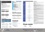
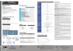
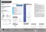
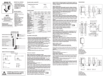
GENERAL DESCRIPTION 8 9 N • Cubic miniaturized photoelectric sensor Background Suppression • Red Hi Power Emission or IR emission • Sensing distance adjustment by trimmer • Output state selectable Lo/Do • Complete protection against electrical damages ELECTRICAL DIAGRAMS OF THE CONNECTIONS 4 3 3 QMRS/0P-0* (PNP output) 1 Bn 2 Wh 1 Bn QMRS/0N-0* (NPN output) + + + Light On + Light On - Dark On - Dark On 4 Bk 2 Wh 4 BkOutput Digital 3 Bu 3 Bu 4 1 Bn 1 Bn 4 Bk Digital 4 BkOutput 2 Wh Digital Output - - + 3 Bu + Light On + - Dark On - 2 Wh 3 Bu - KEY: BN = brown; BK = black; BU = blue 1 Bn 2 Wh 4 Bk 3 Bu DIMENSIONS 1 Bn + + Cable model 2 Wh 2 Wh Double Digital Output Double Digital Output NO 4 Bk 4 Bk NC 3 Bu 1 Bn NO NC - - 3 Bu 1 Bn NC C G L HD H D + S Digital Output0 0 Light On P Dark On N 0 A F 1 Cable 4 Bk exit; 2 Trimmers; Double3Digital Led;Output 4 3Mounting Holes Bu - QMIS/0*-0* 30...200 mm (1) 30...400 mm (1) Sensitivity adjustment Differential travel ≤ 10% Direct diffuse with sens. adj. 100 mm Ripeat accuracy 5% Direct diffuse with sens. adj. 400 mm Light on-Dark on select. yes Direct diffuse with sens. adj. 1,000 mm Operating voltage Ue Direct diffuse with sens. adj. 1,500 mm Ripple 5 m reflex polarized with senisitive adjustment Load current max Emitter with adjustment 20 m (R) or 30 m (IR) receiver without adjustement 30...200 mm (R) or 30...400 mm (IR) background suppression Emitter without check, LO/DO selectable Emitter PNP output - 0 10…30 Vdc ≤ 100 mA 2 V max @ 100 mA Output voltage drop Max output switching current 2 Wh 4 Bk 3 Bu + + 2 Wh 1 Bn 4 Bk 4 Bk Digital Output Digital Output 3 Bu M8 plug model - - 1 Bn + 1 kHz Response time ≤ 100 ms Supply electrical protections Polarity reversal, over voltage pulses Output electrical protection Short circuit (auto reset) , over voltage pulses Plastic housing Storage temperature 2 m cable exit LED indicators Yellow (output state LO/DO) Ambient light immunity 10.000 lux sunlight 3.000 lux incandescent lamp Digital4Output Bk 2 Wh 2 Wh 3 Bu 3 Bu Digital Output M12 pig-tail output M8 3 pin pig tail output Protection degree Housing material M8 4 pin pig tail output Optic material 20 cm cable lenght (pig-tail models) Tightening torque Standard model Weight approx. -25°…+70° C (without freeze) 1 Bn 4 Bk 1 Bn + 4 Bk 2 Wh 1 Bn 2 Wh 4 Bk 3 Bu 3 Bu 1 Bn Digital Output Wh Digital2Output Digital Output - + 4 Bk - + 3 Bu + M12 Pig-tail Output - BK Analog Output - 1 Bn - + + 2 Wh Double Digital Output Double Digital Output 4 Bk 3 Bu 4 Bk Digital Output Italian Sensors Technology - - 3 Bu 3 Bu - - 140 150 160 170 180 190 200 Black 6% -‐25 -‐30 -‐40 Distance (mm) QMRS/0*-0* (Spot dimension) Spot Dimension QMRS 15 5 0 20 40 60 80 100 120 140 160 180 200 -5 -10 Distance (mm) QMIS/0*-0* QMIS 10 PA66 5 0 PMMA -‐5 1 Nm 52 g cable, 10 g M8 connector • Make sure that the supply voltage is correctly settled with a ripple corresponding to the values indicated on the catalogue. • In case the noise produced by the power lines exceed the values foreseen by the CE norm (interference immunity), separate the sensor cables from both the power and high tension lines, and insert it in a grounding metal raceway. Moreover, it is advisable to connect the sensor directly to the supply source and not to other devices. • Avoid contact with organic solvents. • Avoid direct exposition of the receiver to strong light or sun light. • Use a wet cloth to clean the optic and then dry it. Mount the unit using the suitable mounting brackets (supplied), connect and align the sensor following the connection diagrams. Place the object to be detected at the required reading distance, checking that the optic axis is perpendicular to the object surface. NOTE In case of reflecting or flat objects, it could be convenient to recline the sensor of some degrees with respect to the perpendicular. Reproducing the worst possible conditions (for example object with dimensions statistically smaller than the usual ones or with parts darkest than the background), place the object as far as possible from the sensor. Adjust light reception setting on Max. the detection distance. Position the object checking that the red beam (if Red High power emission) strikes it. The reception indicator must be permanently switched on, if it switches off or lights, it is necessary to re-adjust the sensor position. If necessary, clean the optic or check the operating conditions. Set the detection distance, remove the object ; the reception indicator must switch off (position A=MAX ). If not, turn the control knob to Min. until the indicator switches off (e.g. position A ). Turn the control knob to Min.. Place the object again. Turn the control knob to Max. until the reception indicator switches on (e.g. position B). If position B < position A, select middle position C. Check overall function. If function is o.k. the setting procedure is over. If the setting is not o.k. check the operating conditions and re-adjust. If position A ≤ position B, background influence is too high. -‐10 -‐15 -‐20 White 90% (90%) White -‐25 Gray Gray 18% (18%) -‐30 Black Black 6% ( 6%) -‐35 -‐45 -‐50 30 50 70 90 110 130 150 170 190 210 230 250 270 290 310 330 350 370 390 Distance (mm) QMIS/0*-0* (Spot dimension) Spot Dimension QMIS 20 15 10 5 0 20 40 60 80 100 120 140 160 180 200 220 240 260 280 300 320 340 360 380 -5 -10 -15 -20 Distance (mm) WARNING These products are NOT safety sensors and are NOT suitable for use in personnel safety application Declaration of conformity M.D. Micro Detectors S.p.A. con Unico Socio declare under our sole responsibility that these products are in conformity with the following EEC directive: 2004/108/ EC and subsequent amendments Digital Output 4 Bk Supply (-) - BU 4 Supply (+) - BN 1 Bn Supply (-) - BU Supply (+) - BN 130 Gray 18% IP67 (EN60529) ADJUSTMENT Output - BK Analog Output 3 Bu Supply (-) - BU - Analog Output Digital Output 3 Bu 1 Bn 2 Wh 4 Bk Analog Output 2 Wh + 4 M8 3 Pins Pig-tail 1 M12 plug cable exit; 2 Trimmers; 3 Led; 4 Mounting Holes 1 Bn + 120 -‐35 CONNECTIONS AND INSTALLATION Output - BK KEY: 110 -‐40 3 - 100 -30°…+80° C (1) White target kodak 90% reflection 200x200 mm Supply (+) - BN 90 -15 M8 4 pin connector exit 2 80 10 Switching frequency NPN output + 70 PNP or NPN NO or NC Operation temperature range M8 4 Pins 1 Bn 60 White 90% -‐20 ≤ 100 mA Output type 50 -‐10 ≤ 10 μA Leakage current 40 -‐15 ≤ 40 mA ≤ 30 mA 30 -‐5 ≤ 10% No load supply current QMRS 10 5 PLUGS 1 Bn QMRS/0*-0* IR (850 nm) Red (630 nm) 7 m reflex with senisitive adjustment 0.05...1.5 m (R) or 0,05...1,0 m (IR) for transparent objects with adjustment 0.4...4 m for transparent objects with adjustment 20 m (R) or 30 m (IR) emitter + receiver kit with adjustment CHARACTERISTIC CURVES yes (4 turns) Infrared emission VE NO NC VF VG 80 Double Digital Output KEY: A VE 80 QMRS/0*-0* Emission + NO 2 Wh 0 Models Sensing distance mm RED emission Standard model + - Difference (mm) • Installation manual / P Spot dimension (mm) PACK CONTENT Miniaturized cubic photoelectric sensor 12.8x21x31.2 mm 8 0 Difference (mm) QM R I B 7 Installation Manual - CAT8BUT1260402 - ENG - Created: 01/04/2014 QM R Spot dimension (mm) QM BGS CODE DESCRIPTION Italian Sensors Technology società di FINMASI GROUP M.D. Micro Detectors S.p.A. con Unico Socio Strada S. Caterina, 235 - 41122 Modena Italy Tel. +39 059 420411 Fax +39 059 253973 www.microdetectors.com [email protected] 400