Download RID LAMBDA
Transcript
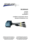
RID LAMBDA Installation and operation manual. Manuale d’installazione e uso. RID (Remote Input Device) modules are optional devices for the expansion of the channels that can be acquired by Stealth GPS-3, Athon XS/XP and DaVinci. I moduli RID (Dispositivo di Ingressi Remoto) sono dispositivi opzionali che consentono l’espansione dei canali acquisibili con Stealth GPS-3, Athon XS/XP e DaVinci. DigiRace-MMX DigiRace-MMX software software For the Data Analysis Per l’analisi dei dati download the scaricare il software DigiRace-MMX software DigiRace-MMX from the Technical Support direttamente dalla pagina di page on our website Supporto Tecnico del sito www.starlane.com www.starlane.com http://www.starlane.com/en_downloads.htm http://www.starlane.com/downloads.htm 1 Contents Contenuti Introduction ................................................................ 3 Functions ............................................................................3 Installation of RID module ........................................... 3 Assembly.............................................................................3 Power supply connection ...................................................4 Module Power On ..............................................................4 Signal connections ..............................................................4 Connecting the engine RPM reading wire ..........................5 Direct electrical connection ...................................5 Introduzione ............................................................... 3 Funzioni ..............................................................................3 Installazione del modulo RID ....................................... 3 Montaggio ..........................................................................3 Collegamento Alimentazione .............................................4 Accensione del modulo ......................................................4 Connessione segnali ...........................................................4 Collegamento del filo di segnale regime motore (RPM).....5 Collegamento elettrico diretto ......................................5 Ignition coil Inductive reading (no electrical connection) ................................................................5 Choosing the main screen............................................ 7 SETTING THE DEVICE ................................................... 7 Checking the firmware version...........................................7 Setting the RPM reading parameters on Stealth GPS-3 .....8 CHANNEL MANAGEMENT ........................................... 9 Distinction between Analog and Digital channels ..............9 Channel setup .....................................................................9 Calibration of analog sensors .............................................9 The calibration screen..................................................10 Calibration of the throttle position sensor (TPS) ..............10 Connecting several RID modules ......................................12 Modifying the CAN BUS address on the RID-LAMBDA module..............................................................................12 Cleaning the surfaces........................................................13 Warranty...........................................................................13 Notes ................................................................................13 Lettura induttiva dalla bobina di accensione (senza connessione elettrica)....................................................5 Scelta della schermata principale ................................ 7 IMPOSTAZIONE DEL DISPOSITIVO................................ 7 Verifica della versione di firmware ....................................7 Impostazione dei parametri di lettura regime motore su Stealth GPS-3 ......................................................................8 GESTIONE DEI CANALI ................................................. 9 Distinzione tra canali Analogici e Digitali ............................9 Impostazione canali ............................................................9 Calibrazione dei sensori analogici.......................................9 La schermata di calibrazione........................................10 Calibrazione del sensore di apertura acceleratore (TPS) ..10 Collegamento di più moduli RID .......................................12 Modifica dell’indirizzo CAN BUS sul modulo RID-LAMBDA12 Pulizia delle superfici ........................................................13 Garanzia ............................................................................13 Note ..................................................................................13 2 Introduction Introduzione Functions Funzioni RID modules are accessory devices connected with Stealth GPS-3, Athon XS/XP and DaVinci devices through the dedicated CAN BUS data line. RIDs are directly supplied by the CAN BUS line cable and their power on and off is controlled by the power on of the main instrument. Each RID module detects signals on connector inputs and transmits them to the instrument storing the data by synchronising them with the position detected by the GPS. All data will be normally downloaded from the instrument and analysed with the DigiRace-MMX software that can be freely downloaded from the site www.starlane.com. I moduli RID sono dispositivi accessori che si collegano ai dispositivi Stealth GPS-3, Athon XS/XP e DaVinci attraverso la linea dati CAN BUS dedicata. I RID ricevono alimentazione direttamente dal cavo della linea CAN BUS ed l’accensione e spegnimento degli stessi sono pilotati dall’accensione dello strumento principale. Ogni modulo RID rileva i segnali sugli ingressi a connettore e li trasmette allo strumento che ne memorizza i dati sincronizzandoli con la posizione rilevata dal GPS. Tutti i dati saranno poi scaricati normalmente dallo strumento e analizzati con il software DigiRace-MMX scaricabile gratuitamente dal sito www.starlane.it. Installation of RID module Installazione del modulo RID Assembly Montaggio RID modules are easily installed into the front fairing or beneath the saddle of a motorcycle or on the floor of a Go Kart or a car. Fasten the RID module by means of the tear Dual Lock system supplied. I moduli RID si installano facilmente nel cupolino o sotto la sella di una moto oppure sul pianale di un Go Kart o di un’auto. Fissare il modulo RID con il sistema Dual Lock a strappo fornito. IMPORTANT: To protect RID module against vibrations, never fix it rigidly to the vehicle and make sure it will never be in contact with any rigid part thereof. IMPORTANTE: Per proteggere il modulo RID dalle vibrazioni, non fissarlo mai in modo rigido al veicolo e controllare che non abbia alcuna parte in contatto con organi rigidi del mezzo. 3 Power supply connection Collegamento Alimentazione RID modules have been designed for series connection between your instrument and its power supply cable by using the POWER SUPPLY -CAN BUS labelled connectors, as it is specified by the wiring diagrams attached to this manual. I moduli RID sono stati progettati per collegarsi in serie tra il vostro strumento e il cavo di alimentazione dello stesso utilizzando i connettori con etichetta POWER SUPPLY -CAN BUS come indicato negli schemi di connessione allegati al presente manuale. ATTENTION!!! For the correct operation of the device you are compelled to connect to ground the black wire 6mm ring (better if directly on the negative pole of battery). Not connecting it can cause malfuncions on data acquisition and the device freezing! ATTENZIONE!!! Per il corretto funzionamento dello strumento è indispensabile collegare a massa il cavo nero con l’occhiello da 6mm (meglio se direttamente al polo negativo della batteria). Il mancato collegamento può causare anomalie nei segnali e il bloccaggio dello strumento! Module Power On Accensione del modulo Once connected the modules will power on and off automatically when the main device is powered on or off. Una volta collegati i moduli RID si accendono e spengono automaticamente all’accensione e spegnimento del dispositivo principale. Attention: Never press the SET button The SET button is needed only to modify the module address on the CAN BUS line. Attenzione: Non premere mai il tasto SET Il tasto SET è utilizzato unicamente per variare l’indirizzo del modulo sulla linea CAN BUS. Signal connections Connessione segnali For the module connection refer to the wiring diagram attached to this manual and observe the instructions here below: Black cable: engine rev signal from the tachometer or the inductive readout of the ignition coil.(see the following section: Connecting the engine RPM reading wire) Yellow cable: Input for a throttle position sensor (TPS) signal available on the vehicle. Per la connessione del modulo riferirsi allo schema di connessione allegato al presente manuale e, nello specifico, seguire le seguenti indicazioni: Cavo nero: segnale dei giri motore proveniente dal contagiri oppure dalla lettura induttiva dalla bobina di accensione. (vedere il seguente paragrafo: Collegamento del filo di segnale regime motore) Cavo giallo: Ingresso per il segnale analogico del sensore posizione farfalla (TPS) disponibile sul veicolo. NOTE: To detect the signal from the original sensors properly, the ground of the instrument shall be also shared by the vehicle. NOTA: Per il corretto rilevamento del segnale dai sensori originali è necessario che la massa dello strumento sia in comune con quella del veicolo. 4 Connecting the engine RPM reading wire Collegamento del filo di segnale regime motore (RPM) Direct electrical connection Collegamento elettrico diretto NOTE: Make sure that the instrument Negative is connected with the vehicle earth. NOTA: Assicurarsi che il negativo dello strumento sia connesso alla massa del veicolo. Option A: Peel and hardwire the black wire directly with the signal wire (0-12 Volt) of the original RPM indicator. Opzione A: Spelare e saldare il filo Nero direttamente al filo di segnale (0-12Volt) del contagiri originale. Attention! On some vehicles the signal of the original speed indicator is not of a 012 Volt type, but it directly comes from the power input wire of one of the ignition coils. This connection would damage the internal RID module circuit. Attenzione! Su alcuni veicoli il segnale del contagiri originale non è di tipo 0-12 Volt ma arriva direttamente dal pilotaggio di potenza di una delle bobine di accensione, tale collegamento danneggerebbe il circuito interno del modulo RID. Ignition coil Inductive reading (no electrical connection) Lettura induttiva dalla bobina di accensione (senza connessione elettrica) Option B1: In the case of Internal Coils built in the cylinder head wind the module black cable with at least 8 turns round the input wires of one of the coils (see Picture, option B1). If the speed readout is not correct, increase the number of turns and check the settings indicated in the paragraph “Setting the RPM reading parameters” in this manual. If there are incorrect instantaneous values, check the Black wire to ensure that it does not receive any interference from the cables of other cylinders, and therefore to make sure that the wire goes through parts of the chassis far from other coils and, if possible, it can be cut to the required length so that it does not receive any undesired signals. Opzione B1: In caso di Bobine Integrate nella testata motore avvolgere il filo nero del modulo con almeno 8 spire attorno ai fili di pilotaggio di una delle bobine (vedere Figura, opzione B1). Se la lettura del regime non è corretta, aumentare il numero delle spire e controllare le impostazioni nel paragrafo “Impostazione dei parametri di lettura regime motore” nel presente manuale . Se si riscontrano valori istantanei non corretti,controllare che il filo Nero non riceva interferenze dai cavi di altri cilindri, verificare quindi che percorra parti del telaio lontane da altre bobine e, se possibile, può essere accorciato alla lunghezza necessaria in modo che non riceva segnali indesiderati. 5 Option B2: In the case of External Coils just put the black cable of the module in contact with the high-voltage coil cable (see figure, option B2) and fasten it by means of two clamps. Opzione B2: In caso di Bobine Esterne sarà sufficiente appoggiare il cavo nero del modulo a contatto con il cavo di alta tensione della bobina (vedere Figura, opzione B2) fissandola con due fascette. Attention! In this kind of installation never remove the BLUE protection cap from the tip of the wire because electric discharges could damage the device. Attenzione! In questo tipo di installazione non rimuovere mai il cappuccio BLU dalla punta del filo perché eventuali scariche elettriche potrebbero danneggiare il dispositivo. Attention! Never connect the RPM reading wire directly to the coil wire to prevent any inadequate voltage irreparably damaging the instrument. Attenzione! Non connettere mai il filo di rilevamento regime motore direttamente ai fili delle bobine poiché le tensioni inadeguate danneggerebbero lo strumento irreparabilmente. IMPORTANT: On Go Karts, Mini and Pocket Bikes and all vehicles with noisy electromagnetic emissions due to the ignition system, it’s necessary to use shielded spark plug caps with internal 5000 ohm resistor. IMPORTANTE: Su Go Kart, Mini moto e Pocket bikes e tutti i veicoli con forti emissioni elettromagnetiche per via del sistema di accensione, è necessario utilizzare cappucci candela schermati con resistenza interna da 5000 ohm. 6 Choosing the main screen Scelta della schermata principale Sia su Stealth GPS-3 che su Athon XS/XP è possibile scegliere la schermata principale desiderata semplicemente premen- On both Stealth GPS-3 and Athon XS/XP you can choose the desired main screen just by pressing the key. do il tasto . While passing on the lap triggers the Laptimer screen will shown for the time set in the Freeze Time setting. Mentre si passa sui traguardi viene mostrata la schermata del cronometro per il tempo impostato alla voce Freeze Time. SETTING THE DEVICE IMPOSTAZIONE DEL DISPOSITIVO Checking the firmware version Verifica della versione di firmware The software installed inside Stealth and Athon and intended to manage all functionalities is referred to as Firmware. Make sure that the Firmware release installed on your device can support RID modules. Access the System Info menu of the device and make sure that the release number next to the Firmware item is: -03.84 or above on Stealth GPS-3 -04.62 or above on Athon XS/XP If the device is complete with a Firmware prior to the one specified, provide for the update by downloading the most recent release from the Technical Support page of the site www.starlane.com and follow the instructions supplied by the device manual for the update. Il software installato all’interno di Stealth e Athon e che ne gestisce tutte le funzionalità ha il nome di Firmware. E’ necessario verificare che il vostro dispositivo abbia installata una versione di Firmware che supporti i moduli RID, Entrare nel menu System Info del dispositivo e verificare che alla voce Firmware sia indicato un numero di versione: -03.84 o superiore su Stealth GPS-3 -04.62 o superiore su Athon XS/XP Se il dispositivo è dotato di Firmware precedente a quello indicato è necessario aggiornarlo scaricando la versione più recente dalla pagina di Supporto Tecnico del sito www.starlane.it e seguire le indicazioni del manuale del dispositivo per effettuare l‘aggiornamento. 7 Setting the RPM reading parameters on Stealth GPS-3 Impostazione dei parametri di lettura regime motore su Stealth GPS-3 Set the number of pulses received for every single revolution of the motor shaft. È necessario impostare il numero di impulsi ricevuti per ogni giro di albero motore. • If the coil should inductively detect the signal on 2-stroke or 4-stroke engines, with no-phased ignition, set the number of pulses to 1. • Se il segnale è rilevato induttivamente dalla bobina su motori 2 tempi o 4 tempi a scintilla persa impostare il numero di impulsi a 1. • If the coil should inductively detect the signal on 4-stroke engines, with phased ignition, set the number of pulses to 0.5. • Se il segnale è rilevato induttivamente dalla bobina su motori 4 tempi con accensione fasata il numero di impulsi deve essere impostato a 0.5. • If the signal is directly detected by the digital signal wire on the original dashboard, set the value according to the system frequency, The correct value is usually 2 on Japanese motor bikes. • Se il segnale è rilevato direttamente dal filo di segnale digitale che va al cruscotto originale il valore va impostato in funzione della frequenza del sistema, di solito su moto giapponesi il valore corretto è 2. Carry out the following operations to set the parameter: Eseguire le seguenti operazioni per impostare il parametro: 8 CHANNEL MANAGEMENT GESTIONE DEI CANALI Distinction between Analog and Digital channels Distinzione tra canali Analogici e Digitali Analog channels shall be understood as all those channels, the value of which will progressively vary according to the quantity acquired. Analog sensors are typically those used to detect quantities, such as temperatures, shifts, pressures, etc. Digital channels typically acquire pulse signals and their value will vary according to the frequency of such pulses. Digital channels are used to acquire signals from phonic wheels mounted on rotary parts, e.g. magnets or bolts on the wheel to detect the speed or the teeth of a flywheel for the engine speed. Per canali Analogici si intendono tutti quelli che hanno una variazione progressiva del valore in funzione della grandezza acquisita, tipicamente i sensori Analogici sono quelli utilizzati per rilevare grandezze quali temperature, spostamenti, pressioni, ecc. I canali Digitali invece acquisiscono tipicamente segnali ad impulsi ed il valore da questi rappresentato è in funzione della frequenza di tali impulsi; vengono quindi utilizzati canali Digitali per acquisire segnali da ruote foniche montate su parti in rotazione; es.: magneti o bulloni sulla ruota per rilevare la velocità o i denti di un volano per il regime motore. Channel setup Impostazione canali Calibration of analog sensors Calibrazione dei sensori analogici The instructions here below are referred to Stealth GPS-3, Athon XS owners can find the instructions on calibration in the manual supplied with the device, in the section “ATHON-XP advanced functions” Le indicazioni che seguono sono relative a Stealth GPS-3, i possessori di Athon XS possono trovare le indicazioni di calibrazione sul manuale in dotazione col dispositivo nella sezione “Funzioni avanzate ATHON-XP” 9 The calibration screen La schermata di calibrazione The following values are shown on the calibration screen: Ax 80.0 = identification of the analog channel (A1 in the example) with the relative instantaneous value converted. Scan = values of the points relative to the instantaneous voltage on the channel. Range = maximum range of the values you wish to assign to the channel. (See here below for a detailed explanation). Min = minimum calibration threshold, in points, from which the signal amplitude starts. (See here below for a detailed explanation). Min = minimum calibration threshold, in points, from which the signal amplitude starts. (See here below for a detailed explanation). Zero = offset value for the zero position of the channel. (See here below for a detailed explanation). Nella schermata di calibrazione sono raffigurati i seguenti valori: Ax 80.0 = identificativo del canale analogico (nell’esempio A1) con il relativo valore istantaneo convertito. Scan = valori dei punti relativo alla tensione istantanea sul canale. Range = campo massimo di estensione dei valori che si vuole attribuire al canale. (Vedi di seguito per spiegazione dettagliata). Min = soglia di calibrazione minima, in punti, da cui parte l’escursione del segnale. (Vedi di seguito per spiegazione dettagliata). Max = soglia di calibrazione massima, in punti, a cui arriva l’escursione del segnale. (Vedi di seguito per spiegazione dettagliata). Zero = valore di offset per la posizione di zero del canale. (Vedi di seguito per spiegazione dettagliata). Calibration of the throttle position sensor (TPS) Calibrazione del sensore di apertura acceleratore (TPS) Access the TPS calibration screen: Range Since the throttle opening is expressed as a percentage by using values between 0% and 100%, the RANGE shall be set to 100. Entrare nella schermata di calibrazione del TPS: Range Poiché l’apertura dell’acceleratore viene espressa in percentuale con valori che vanno da 0% a 100%, il RANGE dovrà essere impostato a 100. Min e Max Una volta definito il RANGE devono essere tarati il minimo e il massimo al fine di allineare la scala 0-100% con l’effettiva corsa Min and Max After having defined the RANGE, calibrate the minimum and maximum value in order to align the 0-100% scale with the actual 10 mechanical stroke of the throttle. Let the throttle closed and acquire the minimum value, as described here below by keeping pressed for 3 seconds the ENTER button on the value field: meccanica dell’acceleratore. Lasciare l’acceleratore in posizione chiusa e acquisire il valore minimo come indicato di seguito mantenendo premuto il tasto ENTER per 3 secondi sulla casella del valore: The value displayed in the Scan field will be set as the new minimum. Now highlight the Max filed and open the throttle completely to acquire the maximum value in the same way by pressing ENTER for 3 seconds. The value displayed in the Scan field will be set as the new maximum. Il valore indicato nella casella Scan sarà quindi impostato come nuovo minimo. Ora posizionatevi sul valore Max e aprite completamente l’acceleratore per acquisire il valore massimo nello stesso modo premendo ENTER per 3 secondi. Il valore indicato nella casella Scan sarà quindi impostato come nuovo massimo. 11 Connecting several RID modules Collegamento di più moduli RID If you wish to increase the number of available channels, you can series-connect up to 4 RID-LAMBDA modules on the CAN BUS line (function available only on DaVinci-R). Every single module has got a specific address, by means of which it is recognised on the CAN BUS line. If you connect more than one module, you are compelled to assign a different address to each module. Qualora si volesse ampliare i canali disponibili è possibile collegare in serie sulla linea CAN BUS fino a 4 moduli RID-LAMBDA (funzione disponibile solo su DaVinci-R). Ogni modulo ha un indirizzo specifico con cui viene riconosciuto sulla linea CAN BUS. In caso si collegassero più moduli è necessario far si che ognuno di questi abbia un differente indirizzo. Modifying the CAN BUS address on the RID-LAMBDA module Modifica dell’indirizzo CAN BUS sul modulo RID-LAMBDA Attention! Never carry out this operation if not necessary. Attenzione! non effettuare tale operazione se non necessaria. 1. Hold down the SET button at least 3 seconds to access the programming mode of the address. Release the key as soon as the LED is fixedly on. The number of LED flashes indicates the current address (e.g. 2 flashes=Address 2), the led repeats the count after a 1-second pause. 1. Tenendo premuto il pulsante SET per almeno 3 secondi si entra in modalità programmazione dell’indirizzo, rilasciare il tasto appena il LED si illumina fisso. Il numero di lampeggi effettuato dal LED indica l’attuale indirizzo (es. 2 lampeggi = Indirizzo 2), dopo una pausa di 1 secondo il led ripete il conteggio. 2. While blinking, press the SET button as many times as the new address value you wish to assign (e.g. 3 times for address 3). 2. Durante il lampeggio premere il pulsante SET tante volte quanto è il valore del nuovo indirizzo che si vuole assegnare (es. 3 volte per indirizzo 3). At the end of the operation, the LED will perform two sequences of the flashes count to confirm that the operation has been successfully carried out and it will restart blinking as in normal operation mode. Power off and on the main device to make the acknowledgement of the new address effective. Al termine dell’operazione il LED eseguirà due volte la sequenza del numero di lampeggi impostato a conferma che l’operazione è andata a buon fine e ritornerà al normale lampeggio operativo. Spegnere e riaccendere il dispositivo principale per rendere effettivo il riconoscimento del nuovo indirizzo. 12 If you just wish to check the address on which the module is set up, follow the procedure at point 1 and count the flashes. After some seconds, it will go back to the operation mode without having changed the address. Se si vuole semplicemente verificare su che indirizzo è impostato un modulo eseguire la procedura al punto 1 e contare i lampeggi. Dopo alcuni secondi tornerà in modalità operativa senza aver variato l’indirizzo. Never set up several devices on the same address, you can set up different addresses up to 10 as a value. Non impostare mai diversi dispositivi sullo stesso indirizzo, è possibile impostare indirizzi diversi fino al valore 10. Cleaning the surfaces Pulizia delle superfici Use a soft cloth wetted with water to clean your RID module. Using alcohol or aggressive detergents might turn the surfaces opaque. Per pulire il vostro modulo RID usate un panno morbido bagnato con acqua, l’uso di alcool o detergenti aggressivi può opacizzare le superfici. Warranty Garanzia RID module is covered by a 12-month warranty for all manufacturing defects. Il modulo RID è coperto da 12 mesi di garanzia sui difetti di fabbricazione. Notes Note IMPORTANT: On Go Karts, Mini Bikes and all vehicles with noisy electromagnetic emissions due to the ignition system, it’s necessary to use shielded spark plug caps with internal 5000 ohm resistor. IMPORTANTE: Su Go Kart, Mini moto e tutti i veicoli con forti emissioni elettromagnetiche per via del sistema di accensione, è necessario utilizzare cappucci candela schermati con resistenza interna da 5000 ohm. RID module is not type-approved for road use. Il modulo RID non è omologato per uso stradale. 13 NOTE: For any update to the present manual please visit the web site: www.starlane.com NOTA: Eventuali aggiornamenti al presente manuale sono disponibili sul sito: www.starlane.it User Guide Version: RIDLMB_002 Versione Manuale: RIDLMB_002 Starlane s.r.l. Via Madonna delle Rose, 70 24061 - Albano S. Alessandro (BG) Italia e-mail: [email protected] http://www.starlane.com 14


