1
U.T.S
ASR
AZIONAMENTO
SBLOCCO
R U O TA
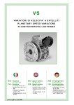
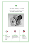
ASR - Riduttori a vite senza fine
tipi RS e RT
C-ASR it Ed01 2007
VARVEL - ASR
AZIONAMENTO SBLOCCO RUOTA
Il dispositivo di sblocco è integrato all’interno di un riduttore a vite senza fine standard delle serie RT o
RS, nelle 28 a 85 e con tutti i rapporti di riduzione, accoppiamenti a motori IEC, alberi uscita, ecc. come
dai relativi cataloghi.
L’innesto è costruito per azionamento con
• comando manuale a volantino;
• comando manuale a leva;
• comando con elettromagnete per comando a distanza.
L’albero di uscita è previsto solo con estremità semplice ed è fornito come standard con le stesse dimensioni dell’albero AS.
L’azionamento può essere eseguito da fermo, durante il funzionamento oppure anche sotto carico con
opportuno dimensionamento delle forze di disinnesto.
Il comando a distanza dell’elettromagnete può essere collegato al motore del riduttore per sbloccaggio
automatico alla mancanza della corrente o alimentato separatamente da una batteria ausiliaria per
sbloccaggio indipendente.
AZIONAMENTI
Leva
Volantino
Elettromagnete
-2-
VARVEL - ASR
VARIANTI COSTRUTTIVE E POSIZIONI DI MONTAGGIO
Varianti di cotruzione
I riduttori con il dispositivo di sbloccaggio ASR sono forniti con la ruota in ghisa sferoidale GS500 - ampiamente dimensionata nella maggioranza delle applicazioni intermittenti per l’azionamento di porte e
cancelli scorrevoli, ma con valori di coppia differenti da quelli riportati nei rispettivi cataloghi MRS-MRT.
Una ruota in bronzo è fornita su richiesta per i casi in cui le coppie o il ciclo di funzionamento richiesti
siano particolarmente severi.
Posizioni di montaggio
Le posizioni di montaggio sono previste in:
• SX - posizione standard
a sinistra visto dal lato motore e-lettrico.
• DX - posizione a richiesta
a destra visto dal lato motore e-lettrico.
Le posizioni di montaggio elencate sono valide per tutte e tre i tipi di azionamento previsti.
I riduttori con il dispositivo di sbloccaggio possono funzionare secondo tutte le posizioni di lavoro previste nei rispettivi cataloghi.
SX
Standard
DX
A richiesta
-3-
VARVEL - ASR
PRINCIPIO DI FUNZIONAMENTO
La trasmissione della coppia fra la ruota e l’albero d’uscita è assicurata da un bloccaggio cava/chiavetta,
che può spostarsi assialmente per permettere il blocco/ sblocco dell’applicazione.
Sbloccaggio
Nella situazione di trasmissione bloccata, la ruota (02) è solidale con l’albero lento (01) per mezzo della
chiavetta (06).
La rotazione del volantino di comando (07) (della leva o la diseccitazione del solenoide) origina lo spostamento dell’albero (03/04) verso l’interno del riduttore, spinge la chiavetta fuori dalla sua sede della
ruota e rende libero l’albero di uscita (01) dalla ruota (02).
Sbloccaggio
Bloccaggio
Nella situazione di trasmissione precedentemente sbloccata, la ruota (02) e l’albero (01) non sono collegati dalla chiavetta (06) e l’albero di uscita è fermo.
La rotazione contraria del volantino di comando (07) (della leva o l’eccitazione del solenoide) origina lo
spostamento dell’albero (03/04) verso l’esterno del riduttore e la molla (11) forza la chiavetta a rientrare automaticamente nella sua cava della ruota dentata.
Bloccaggio
NB - I numeri di riferimento sono elencati nella tabella delle Parti Componenti a pagina 7.
-4-
VARVEL - ASR
TIPI DI INNESTO
Innesto frontale con accoppiamento a chiavetta
Esecuzione standard.
La trasmissione del movimento fra la ruota dentata e l’albero lento si effettua con un accoppiamento a
chiavetta.
Innesto frontale con accoppiamento a denti
Esecuzione a richiesta
La trasmissione del movimento fra la ruota dentata e l’albero lento si effettua con un accoppiamento a
denti.
I tempi d’intervento degli innesti/disinnesti sono ridotti in confronto al tipo con una chiavetta e sono determinati dal numero dei denti.
In generale, sono utilizzati 40 denti per ottenere innesti/disinnesti ogni 8°.
-5-
VARVEL - ASR
DIMENSIONI
RT28
RT40
RT50
RT60
RT70
RT85
A
80
100
120
144
172
206
A1
54
70
80
100
120
140
AA
97
121,5
144
174
205
238
AA1
71
91,5
104
130
153
172
B
53
71
85
100
112
130
B1
44
60
70
85
90
100
C1
31
51
59
70
70
71
C2
30
40
45
50
60
70
D5 ( h6 )
14
19
25
25
28
35
D6
80
80
100
100
100
100
F1
7
7
9
9
11
13
H
40
50
60
72
86
103
H1
57
71,5
84
102
119
135
H2
13
15
20
22
26
33
I
28
40
50
60
70
85
K
57.5
70.5
83-88*
93-94*
117-118*
134-137*
L5
86
100
110
120
120
130
M5
16
21.5
28
28
31
44
N5
5
6
8
8
8
10
S
27,5
38,5
46,5
57
57
67
S1
6
7
8
10
11
14
S2
2,5
2,5
3
3
3
3
V5
M5x10
M8x20
M8x20
M8x20
M8x20
M10x25
Z2
13
13
13 - 18,5
14 - 15
15,5 - 17,5
15,5 - 18,5
* - IEC71-B14 (FRS50) - IEC71-B14 (FRS60) - IEC 80-B14 (FRS70) - IEC 90-B14 (FRS85) - IEC100/112-B14 (FRS110)
Dimensioni non impegnative
-6-
VARVEL - ASR
PART LIST
Item
Description
Item
Description
00
Vite senza fine
13
Spessore
01
Albero lento
14
Boccola
02
Ruota dentata
15
Anello Seeger
03
Albero di comando mobile
16
Paraolio OR
04
Albero di comando fisso
17
Vite
05
Coperchio d’uscita
18
Paraolio
06
Innesto a chiavetta
19
Vite
07
Volantino di comando
20
Leva di comando
08
Albero di comando a leva
21
Vite
09
Coperchio di uscita per leva
22
Vite
10
Chiavetta albero lento
23
Solenoide
11
Molla
24
Vite
12
Spina centraggio chiavetta
-7-
VARVEL - ASR
Estratto delle ISTRUZIONI D’USO E MANUTENZIONE
I riduttori e i variatori di velocità non ricadono nel campo d’applicazione della Direttiva Macchine, art.1(2)
e non possono essere messi in servizio finché la macchina nella quale devono essere incorporati, sia
stata dichiarata conforme all’art. 4(2), all. II(B) delle Direttive Macchine 98/37/CEE/22.6.98 e, solo per
l’Italia, al DL 459/24.7.96.
Installazione
Accertarsi che il gruppo da installare abbia le caratteristiche atte a svolgere la funzione richiesta e che la
posizione di montaggio sia coerente con quanto ordinato. Tali caratteristiche sono deducibili dalla targhetta d’identificazione apposta sul riduttore. Eseguire la verifica della stabilità del montaggio affinché
non si verifichino vibrazioni o sovraccarichi durante il funzionamento.
Funzionamento
Il riduttore può essere collegato per rotazione oraria o antioraria. Arrestare immediatamente il riduttore in
caso di funzionamento difettoso o di rumorosità anomala, rimuovere il difetto o ritornare l’apparecchio
alla fabbrica per un’adeguata revisione. Se la parte difettosa non è sostituita, anche altri componenti possono essere danneggiati con conseguenti ulteriori danneggiamenti e più scarsa possibilità di risalire alle
cause.
Manutenzione
Sebbene i gruppi siano provati con funzionamento senza carico prima della spedizione, è consigliabile
non usarli a carico massimo du-rante le prime 20-30 ore di funzionamento affinché le parti interne possano adattarsi reciprocamente. I riduttori sono spediti già riempiti con olio sintetico a lunga durata e, se occorre sostituire o rabboccare il lubrificante, non mescolare oli a base sintetica con oli a base minerale.
Movimentazione
In caso di sollevamenti con paranco, utilizzare posizioni di aggancio sulla struttura della carcassa, golfari
ove esistenti, fori dei piedi o sulle flange, evitando tutte le parti mobili.
Verniciatura
Qualora il gruppo subisca una verniciatura successiva, è necessario proteggere accuratamente gli anelli
di tenuta, i piani di accoppiamento e gli alberi sporgenti.
Conservazione prolungata a magazzino
Per permanenze maggiori di tre mesi, è consigliata l’applicazione di antiossidanti su alberi esterni e piani
lavorati, e di grasso protettivo sui labbri dei paraolio.
Gestione Ambientale del prodotto
In conformità alla Certificazione Ambientale ISO 14001, sono suggerite le seguenti indicazioni per lo
smaltimento del nostro prodotto:
- gli elementi del gruppo che vengono rottamati devono essere consegnati a centri di raccolta autorizzati
per i materiali metallici;
- gli oli ed i lubrificanti raccolti dal gruppo devono essere smaltiti consegnandoli ai Consorzi Oli esausti;
- gli imballi a corredo dei gruppi (pallet, cartone, carta, plastica, ecc.) vanno avviati per quanto più possibile al recupero/riciclo, consegnandoli a ditte autorizzate per le singole classi di rifiuto.
-8-
ASR
WORMWHEEL
UNLOCK
DEVICE
ASR - Worm Speed Reducers
types RS and RT
C-ASR gb Ed01 2007
VARVEL - ASR
WORM WHEEL UNLOCK DEVICE - SERIE ASR
The unlock device is incorporated inside a standard wormwheel speed reducer of the series RT or RS,
sizes 28 to 85 and all the reduction ratios, IEC motor mountings, output shafts, etc. according to their
specific catalogues.
The clutch is manufactured to be driven
• manually by hand wheel;
• manually by lever;
• electrically by electromagnet for remote control.
The output shaft is made only as single sided spindle and is supplied as standard with the same dimensions of the output shaft AS.
The control can be activated when stand-still, on operation and also on load condi-tions with an adequately sizing of unlocking force.
The electromagnet remote control can be connected to the gearbox motor for an automatic unlocking
at power failure or separately to a separate auxiliary battery for an independent unlock.
DRIVES
Lever
Hand wheel
Electromagnet
-2-
VARVEL - ASR
MANUFACTURING VERSIONS AND POSITIONS
Manufacturing versions
The gear boxes with ASR unlock device are supplied with the wormwheel of spheroidal-graphite cast
iron GS500 - fully dimensioned in the majority of intermittent applications for sliding door and gate driving, but with different torque values from those shown in the relevant catalogues RS and RT.
A bronze wormwheel is supplied on demand for those cases where the requested torque or duty cycle
are particularly severe. .
Manufaacturing positions
The following mounting positions are available:
SX - standard position
left side when looking from electric motor.
DX - on demand position
right side when looking from electric motor.
The above mounting positions are valid for any of the three driving types.
The gearboxes with unlock device can work according to all the installation positions provided for by
the relevant catalogues.
SX
Standard
DX
On demand
-3-
VARVEL - ASR
WORKING PRICIPLE
The torque transmission between worm wheel and output shaft is guaranteed by a key/keyway locking
that can axially shift to allow the consequent application lock/ unlock .
Unlocking
In the blocked transmission situation, the wheel (02) is integral with the output shaft (01) by the means
of the key (06).
The handwheel (07) rotation (lever or solenoid de-energizing) causes the shaft (03/04) shifting towards the gearbox inside, pushes the key out from its keyway in the gear and makes the output shaft
Unlocking
Locking
In the previously unlocked transmission situation, the wheel (02) and the shaft (01) are not connected
by the key (06) and the output shaft is idle.
The counter-rotation of the handwheel (lever or solenoid energizing) origins the shaft (03/04) shifting
towards the gearbox outside and the spring (11) forces the key to automatically re-enter into its keyway of the wormwheel.
Locking
NB - The above reference numbers are traceable in the table of Part List at page 7.
-4-
VARVEL - ASR
CLUTCH TYPES
Key clutch frontal fit
Standard execution.
The motion transmission between the wormwheel and output shaft takes place by a frontal key clutch.
This operation meets the majority of applications with locking/unlocking steps every 180° .
Claw clutch frontal fit
Execution on demand.
The motion transmission between the wormwheel and output shaft takes place by a claw clutch.
Locking/unlocking intervention time is reduced in comparison with one key clutch and the tooth number fixes it accordingly.
Usually, 40 teeth are used to get locking/unlocking every 8°. .
-5-
VARVEL - ASR
DIMENSIONS
RT28
RT40
RT50
RT60
RT70
RT85
A
80
100
120
144
172
206
A1
54
70
80
100
120
140
AA
97
121,5
144
174
205
238
AA1
71
91,5
104
130
153
172
B
53
71
85
100
112
130
B1
44
60
70
85
90
100
C1
31
51
59
70
70
71
C2
30
40
45
50
60
70
D5 ( h6 )
14
19
25
25
28
35
D6
80
80
100
100
100
100
F1
7
7
9
9
11
13
H
40
50
60
72
86
103
H1
57
71,5
84
102
119
135
H2
13
15
20
22
26
33
I
28
40
50
60
70
85
K
57.5
70.5
83-88*
93-94*
117-118*
134-137*
L5
86
100
110
120
120
130
M5
16
21.5
28
28
31
44
N5
5
6
8
8
8
10
S
27,5
38,5
46,5
57
57
67
S1
6
7
8
10
11
14
S2
2,5
2,5
3
3
3
3
V5
M5x10
M8x20
M8x20
M8x20
M8x20
M10x25
Z2
13
13
13 - 18,5
14 - 15
15,5 - 17,5
15,5 - 18,5
* - IEC71-B14 (FRS50) - IEC71-B14 (FRS60) - IEC 80-B14 (FRS70) - IEC 90-B14 (FRS85) - IEC100/112-B14 (FRS110)
Not binding dimensions
-6-
VARVEL - ASR
PART LIST
Item
Description
Item
00
Wormshaft
13
Shim
01
Output shaft
14
Bush
02
Wormwheel
15
Seeger ring
03
Mobile control shaft
16
Oilseal OR
04
Fixed control shaft
17
Screw
05
Output cover
18
Oilseal
06
Key clutch
19
Screw
07
Control handwheel
20
Control lever
08
Lever control shaft
21
Screw
09
Lever output cover
22
Screw
10
Output shaft key
23
Electric solenoid
11
Spring
24
Screw
12
Key centring parallel pin
-7-
Description
VARVEL - ASR
Abstract of OPERATION AND MAINTENANCE INSTRUCTIONS
Variable speed and reduction gearboxes are not part of the field of application of the Machinery Directive, art.1(2),
and they must not be put into service until the machinery into which they are to be incorporated, has been declared
in conformity with the provision of art. 4(2), annex II(B) of Machinery Directives 98/37/CE and for Italy only, of DL
459/96.
The Instructions must be performed by trained and qualified personnel and, in case of Directive Atex, specifically
experienced in potentially explosive zone safety.
Installation
Check if the unit to be installed, is properly selected to perform the required function and that its mounting position
complies with the order. The nameplate reports such information. Check mounting stability to run the unit without
vibrations or overloads.
Running
The unit may be connected for clockwise or counter-clockwise rotation.
The unit must be stopped as soon as defective running or unexpected noise occur, remove the faulty part or return
the unit to the factory for checking. If the faulty part is not replaced, other parts can also be affected, causing more
severe damage and making the identification of initial cause more difficult.
Maintenance
Although the units are no-load run tested in the factory before despatch, it is recommended not to run them at
maximum load for the first 20-30 running hours to allow the proper running in.
The gearboxes are delivered already filled with long-life synthetic oil and, in case of replacement or topping, do not
mix with mineral lubricants.
Handling
Attention, right positioning and stability when handling are essential to avoid subsequent damages in unit operation. When hoisting, use relevant housing locations or eyebolts if provided, or foot or flange holes. Never hoist on
any moving part.
Painting
Carefully protect oil seals, coupling faces and shafts when units are re-painted.
Long-term storage
For storages longer than 3 months, apply anti-oxidants onto shafts and machined surfaces, and protective grease
on oil seal lips.
Storages longer than one year reduce bearing grease lifetime.
Product’s Environmental Management
In conformity with Environmental Certification ISO 14001, we recommend the following to dispose of our products:
- scraped components of the units to deliver to authorized centres for metal object collection;
- oils and lubricants drained from the units to deliver to Exhausted Oil Unions;
- packages (pallets, carton boxes, paper, plastic, etc.) to lead into regeneration/recycling circuits as far as possible,
by delivering separate waste classes to authorized companies.
-8-
RS & RT
RIDUTTORI A VITE SENZA FINE
WORM GE ARBOXES
SCHNECKENGETRIEBE
RS & RT
Riduttori
a vite senza fine
Singola, precoppia e doppia
riduzione
• 7 grandezze RT
• 9 grandezze RS
• Potenze da 0.09 a 15 kW
• Rapporti da 5:1 a 10000:1
• Coppie da 8 a 3020 Nm
-1
(con entrata 1400 min )
C-MRS-MRT it gb de Ed02 2007
RS & RT
Worm
speed reducers
RS & RT
Schneckengetriebe
Single, attachment and double
stage
• 7 sizes RT
• 9 sizes RS
• Powers from 0.09 to 15 kW
• Ratios from 5:1 to 10000:1
• Torques from 8 to 3020 Nm
(with 1400 rpm input)
Ein-, vor- u.
zweistufig
• 7 Größen RT
• 9 Größen RS
• Leistungen von 0.09 bis 15 kW
• Untersetzungen von 5:1 bis
10000:1
• Ausgangsdrehmoment von 8
bis 3020 Nm (mit Eingang
-1
1400 min )
VARVEL - RS & RT
RIDUTTORI SERIE RS E RT
GEARBOXES SERIES RS AND RT
GETRIEBEBAUREIHE RS U. RT
Vite senza fine singolo
Single worm gears
Einstufig Schneckengetriebe
I riduttori delle serie RS e RT, specificatamente concepiti per fissaggio universale,
sono costruiti con carcassa e coperchi in
alluminio pressofuso fino alla grandezza
85 e in ghisa dalla grandezza 110.
Le coppie indicate nelle tabelle di selezione sono coppie di uscita relative alla
grandezza considerata e le potenze sono
riferite a 1440 min-1.
I paraolio entrata in Viton, montati su richiesta, rendono possibili senza problemi
gli azionamenti con motori a 2 poli o motori c.c. a 3000 min-1.
I riduttori sono spediti già riempiti con
lubrificante sintetico a lunga durata (senza
tappi), nelle quantità indicate a pag. 9 e
valide per qualunque posizione di
funzionamento.
I valori delle tabelle di selezione sono intesi per fattore di servizio FS1.0, vale a
dire con funzionamento di 8-10 ore al
giorno, con carico uniforme, avviamenti
inferiori a 6 all’ora e temperatura ambiente
fra 15 e 35 °C.
The worm gearboxes, RS and RT series,
specifically designed for universal mounting, are manufactured with die cast housings and covers in aluminium up to the
size 85 and cast iron from the size 110.
Torques listed in selection tables are output torque values for the specific size, and
motor powers are always referred to 1440
rpm.
Input Viton oil seals, fitted on demand, allow free-trouble operation with 2-pole
standard ac motors or 3000 rpm dc motors.
Gearboxes are delivered filled with synthetic long-life oil (without plugs), in quantities as recommended on page 9, and
valid for all mounting positions.
Selection table data are intended for service factor SF1.0 i.e. 8-10 running hours
per day, uniform load, less than 6 start/
stops per hour, and room temperature
ranging from 15 to 35 °C.
Die Getriebe der Serien RS u. RT, eigens
für die universelle Montageanordnung
entwickelt, haben bis zur Baugröße 85
Gehäuse und Deckel aus AluminiumDruckguß und aus Guß bei Baugröße
110. Die in den Auswahltabellen genannten Drehmomente sind jeweils die Ausgangsdrehmomente der entsprechenden
Baugröße, und die Leistungen beziehen
sich auf eine Nenndrehzahl von 1440
1/min. Wellendichtringe aus Viton, auf
Anfrage auf der Eingangsseite montiert,
ermöglichen einen problemlosen Einsatz
von 2-poligen Motoren oder Gleichstrommotoren bis 3000 1/min im Dauerbetrieb.
Die Getriebe werden ausgeliefert mit
Langzeitschmier-mittelfüllung (ohne zusätzliche Verschluß-schrauben) und sind
für alle Montagepositionen ausreichend
befüllt. Die Tabellenwerte berücksichtigen
einen Betriebsfaktor von FS 1.0, d.h. Betrieb 8-10 Stunden/Tag, gleichmäßige
Belastung, weniger als 6 Schaltvorgängen
(Start und Halt) je Stunde und Umgebungstemperaturen zwischen 15 und 35
°C .
Vite senza fine con precoppia
Helical worm gears
I riduttori delle serie RA eTA, composti da
un riduttore FXA indipendente a una
coppia di ingranaggi montato su un
riduttore standard del tipo FRS o FRT,
forniscono una maggior coppia di uscita ed
un più elevato rendimento degli equivalenti
rapporti del tipo RT.
The gearboxes, RA and TA series, made
up of an independent single stage helical
gearbox FXA fitted to a standard FRS or
FTR gearbox, allow greater output torques
and higher efficiency than the FRS and
FRT gearbox with equivalent ratios.
Schneckengetriebe
stufe
Vite senza fine - doppio stadio
Two stage worm gears
Doppelstufige Schneckengetriebe
I riduttori della serieRS/RS e RT/RT sono
composti di due riduttori della serie RS o
RT e forniscono un’ampia scelta di elevati
rapporti a completamento della serie RA e
TA per ottenere rotazioni alle più basse
velocità.
The gearboxes, RS/RS and RT/RT series,
are made up of two gearboxes RS or RT
and offer a full selection of high reduction
ratios to obtain the very low output
speeds.
AS, AD - Albero di uscita
AS, AD - Output shafts
Die Getriebe der Serie RS/RS u. RT/RT
sind eine Kombination zweier Schneckengetriebe der RS oder RT Baureihe und
bieten eine weitgehende Auswahlmöglichkeit an hohen Untersetzungen und somit
sehr kleinen Abtriebsdrehzahlen.
AS, AD - Ausgangswelle
Tutti i tipi di riduttori sono normalmente
costruiti con albero uscita cavo e, a richiesta, l’albero lento sporgente in acciaio C43
può essere fornito semplice AS o doppio
AD. Su richiesta è disponibile una protezione di sicurezza ASC dell’estremità non
utilizzata dell’albero AS.
All the gearboxes are manufactured with
hollow output shaft as standard version
and, optionally, a single AS or double AD
solid output shaft - made of steel C43 can be supplied.
An ASC safety shield for the opposite side
of a single output shaft AS, is available on
demand.
Alle Getriebe werden in Hohlwellen-Ausführung hergestellt. Als Zubehör können
Einsteckwellen in der Version AS als einseitige Welle oder AD als beidseitige
Welle geliefert werden. Diese Einsteckwellen sind aus C43 Stahl gefertigt. Auf
Anfrage ist auch ein Wellenschutz ASC
als Abdeckung eines Hohlwellenendes
lieferbar.
Braccio di reazione
Torque arms
Drehmomentstütze
I riduttori standard sono forniti normalmente su entrambi i lati con coperchi che
permettono il fissaggio del braccio di reazione, quando essi debbono funzionare
come riduttori pendolari. Il braccio reazione, standard o con boccola antivibrante
in Vulkollan, è costruito in lamiera ad elevato spessore e zincato bianco.
Standard gearboxes are supplied normally
with covers on each side allowing torque
arm fixing when gearboxes have to operate as shaft mounted units.
The torque arm, standard or with Vulkollan
vibration-damping, is made of extra thick
plate and white galvanized.
Die Getriebe werden normalerweise mit
Deckeln auf beiden Abtriebsseiten geliefert, die Bohrungen und Zentrierung für
die Befestigung einer Drehmomentstütze
besitzen, wenn das Getriebe in der Aufsteckversion eingesetzt wird. Die Drehmomentstütze, standard oder mit Dämpfungsbuchse aus Vulkollan, ist aus starkem verzinkten Blech hergestellt.
- 2 -
mit
Stirnradvor-
Die Getriebe der Serien RA u. TA, bestehen
aus einer Kombination eines separaten einstufigen Stirnradgetriebes FXA, mit einem
Standard FRS oder FRT Schneckengetriebe
und erlauben ein größeres Abtriebsdrehmoment bei besserem Wirkungsgrad als einstufige FRS u. FRT- Schneckengetriebe mit
gleicher Übersetzung.
VARVEL - RS & RT
RIDUTTORI SERIE RS E RT
GEARBOXES SERIES RS AND RT
GETRIEBEBAUREIHE RS U. RT
TLI/TLE - Limitatore di coppia
TLI/TLE - Torque limiters
TLI/TLE- Drehmomentbegrenzer
Il dispositivo limitatore di coppia - TLI realizzato all’interno del riduttore e TLE installabile esternamente - permette la regolazione della coppia trasmissibile, la
protezione del motoriduttore in caso
d’ostacolo accidentale, il semplice sblocco
del sistema e la manovra manuale in caso
di mancanza di corrente. Il valore della
coppia di slittamento, tarato in fabbrica, è
regolabile in diminuzione dal valore di
coppia massima a zero e la rotazione
dell’albero di uscita riprende quando la
coppia ridiscende al disotto del valore
prefissato. Le quantità d’olio del limitatore
TLI sono riportate a pagina 32 e 40.
The torque limiter and safeguard device TLI built-in inside the gearbox and TLE
fitted outside - allows easy torque adjustments, full gearbox safeguard against unexpected overload conditions, simple hand
release, and manual operation in case of
power supply failure.
Slipping torque, factory preset, can be
adjusted from the maximum pre-set torque
down to zero, and shaft rotation restarts
automatically as soon as torque value is
lower than the pre-set value.
Oil quantity of torque limiter TLI are listed
at page 32 and 40.
Die TL Einrichtung ermöglicht die Einstellung der übertragbaren Drehmomente,
die Absicherung vom Getriebe gegen
Spitzenbelastungen, die einfache Ausschaltung der Antriebseinheit und die manuelle Bedienung im Falle eines Stromansfalles. Das Rutschmoment ist vom
max. Einstellmoment bis zum Nullwert einstellbar und die Drehbewegung der Abtriebswelle setzt wieder ein, sobald das
Drehmoment wieder kleiner als das eingestellte Moment wird.
Ölmenge: Seite 32 u. 40
SL - Limitatore di giri
SL - Travel limiters
SL-Drehzahlbegrenzer
Il dispositivo SL arresta - per mezzo di fine
corsa interni - il funzionamento del motoriduttore dopo un tempo prefissato. La filettatura standard permette circa 40 giri dell’albero
di uscita. L’escursione dei fine corsa è
regolabile e il tempo di funzionamento varia da
12 a 170 secondi in relazione al rapporto
utilizzato.
The SL travel limiter device stops - by
means of built-in limit switches - the gearbox after a given operation time.
Standard thread allows approx. 40 turns of
the output shaft. Limit switch travel is adjustable and operation time varies upon
the used reduction ratio from min. 12 to
max. 170 seconds.
Die SL-Einrichtung stoppt, mittels eingebauten Wegschalter, das Getriebe nach
einer bestimmten Zeit. Die Standardgewindespindel, ermöglicht ca. 40 Umdrehungen der Ausgangswelle. Die Wegschalter sind einstellbar und die Betriebszeit ist, abhänging von der Untersetzung,
zwischen min. 12” bis max. 170”.
Direttiva ATEX
Directive ATEX
ATEX Richtlinien
I riduttori VARVEL-ATEX, fornibili su
richiesta, sono progettati e costruiti in
accordo alla Direttiva 94/9/CE “Atex” e
sono pertanto idonei alla installazione in
atmosfere potenzialmente esplosive:
• Zone di Gruppo II,
• Categoria 2 (o 3),
• Pericolo di esplosione in presenza di
Gas (Zona 1 o 2),
• Pericolo di esplosione in presenza di
Polveri combustibili (Zona 21 o 22).
The gearboxes VARVEL-ATEX, delivered
on demand, are designed and manufactured according to Directive 94/9/CE “Atex”
and therefore, they are qualified for installation in potentially explosive atmospheres:
• Zones of Group II,
• Category 2 (or 3),
• Explosion hazard with gas presence
(Zone 1 or 2),
• Explosion hazard with combustible dust
presence (Zone 21 or 22).
Die Getriebe Varvel-Atex, ausschließlich
auf Anfrage geliefert, sind entsprechend
den Atex-Richtlinien 94/9/ EG "ATEX“
konstruiert und hergestellt und somit zugelassen für die Installation in potentiell
zündfähigen Atmosphäre:
• Gefahrenbereiche der Gruppe II
• Kategorie 2 (oder 3)
• Explosiongefärdeter Bereich mit Gase
(Gefahrenbereiche 1 oder 2)
• Explosiongefärdeter
Bereich
mit
zündfähigen Stäube (Gefahrenbereiche
La serie VARVEL-ATEX viene identificata The units VARVEL-ATEX are identified by
21 oder 22).
the additional marking
mediante la marcatura supplementare
Die Varvel-Atex Produkte sind mit folgenden zusätzlichen Stempelung verseII 2 GD ck IP66 Tmax=135 °C
II 2 GD ck IP66 Tmax=135 °C
hen:
II 2 GD ck IP66 Tmax=135 °C
- 3 -
VARVEL - RS & RT
RIDUTTORI SERIE RS E RT
GEARBOXES SERIES RS AND RT
GETRIEBEBAUREIHE RS U. RT
SPECIFICHE
GENERALI
GENERAL
SPECIFICATIONS
ALLGEMEINE
EIGENSCHAFTEN
Gamma
Range
Bereich
Grandezze : 9 RS + 7 RT
55 rapporti di riduzione
3020 Nm coppia uscita max
Sizes: 9 RS + 7 RT
55 reduction ratios
3020 Nm max. output torque
Baugrößen: 9 RS + 7 RT
55 Übersetzungen
3020 Nm max. Abtriebsmoment
Dimensionamento
Sizing
Auslegung
Secondo BS721.
Vita media 15.000 ore con fattore
di servizio SF1
According to BS721.
15,000 hrs average lifetime with
service factor SF1
EntsprechendBS721 15T Stunden
Lebensdauer für Verzahnung und
Lagerung bei einem Bfaktor SF1
Carcassa, Coperchi
Housing, Covers
Gehäuse, Flansche
Pressofusione in alluminio
AlSi12Cu2Fe fino grandezza 85 e
ghisa G25 dalla grandezza 110.
Pressure die cast aluminium
AlSi12Cu2Fe till size 85 and cast
iron from size 110.
Aluminium-Druckguss
AlSi12Cu2Fe bis Größe 85 und
G25 vom Größe 110.
Parti dentate
Toothed parts
Verzahnung
Viti in acciaio 20MnCr5 cmt / tmp
con profilo ZK rettificato. Ruote in
bronzo CuSn12 su mozzo in ghisa.
Worms of steel 20MnCr5 CH and
tooth profile ZK ground. Wheels of
bronze CuSn12 on CI hub.
Stahl 20MnCr5 einsatzgehärtet.
Zahnprofil geschliffen. Schneckenrad in Bronze CuSn12 HW Roheisen
Alberi & Linguette
Shafts & Keys
Wellen u. Passfedern
Acciaio C43
Alberi h6 - Fori E8
Linguette secondo DIN6885 B1
Steel C43
Shafts h6 - Bores E8
Keys according to DIN6885 B1
Stahl C43
Wellen h6 – Bohrungen E8
Passfedern nach DIN6885 B1
Cuscinetti
Bearings
Lagerung
Sfere o rulli
secondo grandezza e specifiche
tecniche
Ball- or roller-types
according to sizes and technical
requirements
Kugel- oder Rollenlager
entsprechend den technischen
Vorschriften
Paraolio
Oil seals
Dichtungen
Tipo NB - nitril-butadiene
con secondo labbro parapolvere
secondo DIN 3760
Type NB - nitril-butadiene
with additional anti-dust lip
according to DIN 3760
Typ NB – Nitril-Butadien
mit zusätzlicher Staublippe
entsprechend DIN 3760
Lubrificante
Lubricant
Schmierung
Olio sintetico a lunga durata
Gradazione ISO VG 320
Synthetic long-life oil
Grade ISO VG 320
Synthetisches Getriebeöl ISO VG
320 als Langzeit-Füllung
Verniciatura a forno
Baking painting
Gehäuselackierung
RS/RT ≥110: vernice a polveri
epossidiche, colore std RAL 7012.
RS/RT28-85: alluminio naturale.
RS/RT ≥110: epoxy powder
paint,std colour RAL 7012.
RS/RT28-85: real aluminium.
RS/RT ≥110: Epoxydpulverfarbe
Standardfarbton RAL 7012
RS/RT28-85: Aluminium.
- 4 -
VARVEL - RS & RT
DESIGNAZIONE
DESIGNATION
BEZEICHNUNGEN
DESIGNAZIONE DEL RIDUTTORE
F RT
[../] 40
B3
BEZEICHNUNG GETRIEBE
GEARBOX DESIGNATION
28 IEC71 B14
(OPS, OPP)
OPS= Opzioni standard pag.34-42 - Standard options page 34-42
Standard Optionen Seite 34-42
OPP= Opzioni piè pagina - Options at the foot of the page Optionen siehe Seitenende
B5, B14 = Forma motore - Motor form - Motorbauform
Grandezza motore elettrico - Electric motor frame - Motorbaugroße
Rapporto di riduzione - Reduction ratio - Untersetzungsverhältnis
Forma costruttiva - Mounting form - Montageposition
28, 40, 50, 60, 70, 85, 110, 130, 150 = Grandezza riduttore - Gearbox size - Baugröße
63/, 71/, 80/ = Grandezza precoppia - Helical stage size - Baugröße Vorstufe
28/, 40/, 50/ = Grandezza 1° riduttore - 1st RT/RT gearbox size - Baugröße Getriebe 1.
RS, RA, RS/RS, RT,TA, RT/RT = Tipo riduttore - Gearbox type - Getriebetyp
M = Motoriduttore
- Geared motor
- Getriebemotor
F = Flangia entrata IEC
- IEC input flange
- Eingangsflansch IEC
S = Senza flangia IEC
- Without IEC input flange - Ohne Flansch IEC
… = Senza flangia d’entrata
- Free input shaft
- freie Eingangswelle
DESIGNAZIONE DEL MOTORE
MT
0.37kW 71B
4 B14
BEZEICHNUNG MOTOR
MOTOR DESIGNATION
230/400/50
IP55 F X1
Posizione morsettiera - Terminal box position - Klemmenkastenlage
Cl. F (std) = Classe isolamento - Insulation class - Isolationsklasse
IP55 (std) = Grado protezione - Protection class - Schutzart
Tensione/frequenza - Voltage/frequency - Spannung/Frequenz
Forma costruttiva - Mounting - Bauform
X3
X3
Numero poli - Number of poles - Polzahl
Grandezza IEC motore - IEC motor size - Baugröße Motor
X4
X2
Potenza motore - Motor power - Leistung Motor
MT = Motore trifase
MM = Motore monofase
- Three-phase motor
- Single-phase motor
MA = Motore autofrenante - Brake motor
- Dreiphasen-Motor
- Einphasen-Motor
- Bremsmotor
X2
X4
(std)
X1 (std)
X1
OPZIONI OPP
OPTIONS OPP
OPTIONEN OPP
L’allestimento standard, ove non diversa- Standard fitting side, unless otherwise re- Die Standardausführung, wenn nicht gemente richiesto, è montato sul lato destro quested, is the right side of the gearbox sondert angefragt, wird auf die rechte
visto dall’entrata.
when seen from the input side.
Seite, vom Eingang her betrachtet, montiert.
ACø - Albero cavo non std ø..
ACø - Not std hollow shaft ø..
ACø - Sonderhohlwelle ø..
CS
- Sonderlager Ausgang
CS
- Cuscinetti uscita non std
CS
- Not std output bearings
F
- Flangia uscita F aggiuntiva
F
- Additional output flange F
FL
- zusätzlicher FL Ausgangsflansch
GRI - Gioco ridotto dentatura
GRI - Reduced gearing backlash
GRI - spielarme Verzahnung
GRM - Gioco ridotto montaggio
GRM - Reduced end play
GRM - spielarme Montage
LNS - Lubrificazione non std
LNS - Not std lubrication
LNS - Sonderschmierung
VB
- Schneckenwelle beidseitig
VB
- Vite bisporgente
VB
- NDE worm shaft extension
- 5 -
VARVEL - RS & RT
RS-RA-RS/RS
POSIZIONI DI MONTAGGIO
STANDARD MOUNTING POSITIONS
MONTAGEPOSITION
RS , RA , RS/RS
Uscita - Output - Ausgang
S ( SA )
I ( IA )
B3 (std)
D ( DA )
B3 (std)
PC - PC
B3 (std)
FL ( FA,FB ) & ( PA,PB )
B5 (std)
B5 (std)
B5a
B5i
V5
V5
V5
B5
B8
B8
B8
B5
V6
V6
V6
B5
B5c
B5ci
B6
B6
B6
V1
V1
V1i
B7
B7
B7
V3
V3
V3i
11
12
13
RA
Entrata - Input - Eingang
10 (std)
- 6 -
B5b
B5ai
B5bi
VARVEL - RS & RT
RS/RS
POSIZIONI DI MONTAGGIO
STANDARD MOUNTING POSITIONS
MONTAGEPOSITION
RS/RS
Uscita - Output - Ausgang
S ( SA )
I ( IA )
D ( DA )
11
12
13
14
15
16
17
18
- 7 -
PC ( PA, PB )
FL ( FA, FB )
VARVEL - RS & RT
RT-TA-RT/RT
POSIZIONI DI MONTAGGIO
STANDARD MOUNTING POSITIONS
MONTAGEPOSITION
RT
TA
RT/RT
B3 (std)
B6
B7
B8
V6
F (std)
Fi
10 (std)
11
12
13
20 (std)
21
22
23
24
25
26
27
Uscita
Output
Ausgang
V5
TA
Entrata
Input
Eingang
RT/RT
Entrata
Input
Eingang
- 8 -
VARVEL - RS & RT
FATTORI DI SERVIZIO - PESI & LUBRIFICANTI - CARICHI ENTRATA
SERVICE FACTORS - WEIGHTS & LUBRICANTS - INPUT LOADS
BETRIEBSFAKTOREN - GEWICHTE U. SCHMIERMITTEL - EINGANGSKRÄFTE
FATTORI DI SERVIZIO
SERVICE FACTORS
BETRIEBSFAKTOREN
FS = F1 x F2
RS-RT
- PESI &
LUBRIFICANTI
- WEIGHTS &
LUBRICANTS
- GEWICHTE &
SCHMIERMITTEL
kg
F1
a
b
c
F2
d
3-4h
0.8
1.0
1.5
6
1.0
8 - 10 h
1.0
1.2
1.8
60
1.2
10 - 24 h
1.4
1.6
2.0
120
1.4
a = Carico uniforme
Uniform load
gleichmäßige Belastung
b = Carico variabile
Variable load
variable Belastung
c = Carico ad urti
Shock load
Stoßbelastung
d = Avviamenti/ora
Start/stops per hour
Schaltungen/Stunde
l
RA-TA
kg
l1/l2
RS / RS
RT / RT
kg
l1/l2
28
1.1
0.03
63 / 40
4.0
0.04/0.08
28 / 28
2.5
0.03/0.03
40
2.5
0.08
63 / 50
5.3
0.04/0.13
28 / 40
3.9
0.03/0.08
50
3.8
0.13
63 / 60
8.0
0.04/0.20
28 / 50
5.2
0.03/0.13
60
6.5
0.20
71 / 50
6.6
0.06/0.13
28 / 60
7.9
0.03/0.20
70
9.0
0.35
71 / 60
9.3
0.06/0.20
40 / 70
12.0
0.08/0.35
85
13.5
0.60
71 / 70
11.8
0.06/0.35
40 / 85
16.5
0.08/0.60
110
39.0
1.50
71 / 85
16.3
0.06/0.60
50 / 110
45.0
0.13/1.50
* 130
50.0
2.75
80 / 60
10.5
0.10/0.20
*60 / 130
57.0
0.25/2.75
* 150
80.0
4.40
80 / 70
13.0
0.10/0.35
*70 / 150
90.0
0.35/4.40
80 / 85
17.5
0.10/0.60
80 / 110
43.0
0.10/1.50
100 /110
46.0
0.20/1.50
*100/130
64.0
0.20/2.75
*100/150
\94.0
0.20/4.40
* - Solo, Only , Nur RS
R1
R1
A1
CARICHI RADIALI ENTRATA R1 [daN]
A1
INPUT RADIAL LOADS R1 [daN]
RADIALKRÄFTE EINGANG R1 [daN]
A1 = 0.2 x R1
min-1
2800
1400
900
700
500
300
RS-RT 28
5
7
8
9
10
12
RS-RT 40
11
15
16
17
18
20
RS-RT 50
15
20
22
25
28
30
RS-RT 60
23
30
33
35
37
40
RS-RT 70
26
35
40
44
47
50
RS-RT 85
34
45
52
58
62
70
RS-RT 110
57
75
80
85
92
100
RS 130
70
100
105
110
115
120
RS 150
90
120
125
130
140
150
- 9 -
VARVEL - RS & RT
CARICHI ESTERNI
OUTPUT LOADS
AUSGANGSKRÄFTE
R2
CARICHI RADIALI R2 [daN] CON CUSCINETTI STANDARD
RADIAL LOADS R2 [daN] WITH STANDARD BEARINGS
R2
A2
A2
RADIALKRÄFTE R2 [daN] MIT STANDARDLAGERUNG
A2 = 0.2 x R2
min-1
280
200
140
93
70
50
35
29
25
20
18
14
Brg No.
RS-RT28
---
45
50
55
60
62
70
75
80
90
95
100
16005
RS-RT40
100
100
110
120
135
150
160
170
180
190
200
230
16006
RS-RT50
145
125
145
170
190
200
230
240
260
280
290
320
16008
RS-RT60
225
240
250
290
330
360
390
430
460
500
530
560
RS-RT70
260
270
290
360
390
420
450
520
550
590
630
670
RS-RT85
330
330
370
440
470
540
550
630
660
710
750
830
RS-RT110
---
390
415
520
540
590
570
750
780
800
880
980
RS130
---
500
585
615
650
660
780
880
950
970
1050
1150
6015
RS150
---
650
770
830
880
900
1100
1200
1250
1300
1400
1500
6216
RS: 6008 / RT: 6208
RS: 6009 / RT: 6209
RS: 6010 / RT: 6210
RS: 6012 / RT: 6212
R2
CARICHI RADIALI R2 [daN] CON CUSCINETTI RINFORZATI
RADIAL LOADS R2 [daN] WITH HEAVY DUTY BEARINGS
R2
A2
A2
RADIALKRÄFTE R2 [daN] MIT VERSTÄRKTER LAGERUNG
A2 = 0.2 x R2
min-1
280
200
140
93
70
50
35
29
25
20
18
14
Brg No.
RS-RT28
---
65
75
82
90
93
105
112
120
130
130
130
6005
RS-RT40
140
150
155
165
190
210
225
240
250
260
260
260
32006
RS-RT50
200
175
200
240
260
300
340
360
390
420
420
420
32008
RS-RT60
290
300
320
370
420
480
510
570
610
660
660
660
30208
RS-RT70
335
330
370
450
516
560
610
690
730
790
790
790
RS-RT85
410
420
460
550
630
720
730
840
870
940
940
940
RS-RT110
---
500
540
670
750
800
930
1050
1110
1110
1110
1110
RS130
---
700
790
860
970
990
1170
1290
1420
1450
1450
1450
32015
RS150
---
900
1080
1160
1320
1350
1650
1800
1870
1950
1950
1950
30216
RS:32009 / RT: 30209
RS: 32010 / RT: 30210
- 10 -
RS:32012 / RT: 30212
VARVEL - RS & RT
GRANDEZZE MOTEURI “RS - RT”
MOTOR FRAMES “RS - RT”
BAUGRÖßEN MOTOR “RS - RT”
FRS
FRT
28
40
50
60
70
min-1
i=5
7
10
15
20
28
40
49
56
70
80
100
IEC
280
200
140
93
70
50
35
29
25
20
18
14
56
---
63
---
56
63
71
63
71
80
71
80
90
71
80
90
80
90
---
100/112
---
132
---
90
---
100/112
---
132
---
90
---
100/112
---
132
---
160
---
100
85
100/112
110
130
150
-
90
B5 & B14
B5
B5 & B14
B5
(Giunto G - Coupling G - Kupplung G)
(Giunto G - Coupling G - Kupplung G)
(Foro IEC - IEC bore - Bohrung IEC)
(Foro IEC - IEC bore - Bohrung IEC)
- 11 -
VARVEL - RS & RT
GRANDEZZE MOTORI “RA - TA”
MOTOR FRAMES
“RA - TA”
BAUGRÖßEN MOTOR “RA - TA”
FRA
FTA
IEC
7
10
15
20
28
40
49
56
70
80
100
*
**
**
**
**
**
**
**
**
**
**
**
63/40
56
63/50
B5&B14
---
---
---
---
63/60
63/40
63
63/50
B5&B14
---
---
---
---
63/60
71/50
71
71/60
B5&B14
71/70
71/85
---
---
---
---
---
80/60
80
80/70
B5&B14
80/85
80/110
80/60
90
80/70
B5&B14
80/85
80/110
100/110
100/130
100/150
90
B5&B14
100
B5&B14
90
B5&B14
100
B5&B14
*
**
- Entrata precoppia
- Uscita precoppia & Entrata
FRS/FRT
*
**
- Helical stage input
- Helical stage output & FRS/FRT
input
*
**
- Eingang der Vorstufe
- Ausgang der Vorstufe u. Eingang
der Getriebe FRS/FRT
- ø105 x14
- ø120 x 19
- ø140 x 24
- ø140 x 28
- ø200 x 28
- ø200 x 28 (Foro vite ø38 mm
& Boccola ø38/ø28)
- ø105 x14
- ø120 x 19
- ø140 x 24
- ø140 x 28
- ø200 x 28
- ø200 x 28 (Wormshaft bore ø38 mm
& Adaptador ø38/ø28)
- ø105 x14
- ø120 x 19
- ø140 x 24
- ø140 x 28
- ø200 x 28
- ø200 x 28 (Schneckebohrung ø38 mm
u. Buchse ø38/ø28)
- ø120 x 14
- ø120 x 14
- ø120 x 14
- ø140 x 19
- ø140 x 19
- ø140 x 19
- 12 -
RS-RT (2800 min-1)
VARVEL - RS & RT
TABELLA SELEZIONE
SELECTION TABLE
AUSWAHLTABELLE
RS
RT
i=
RS - RT 28
RS - RT 40
RS - RT 50
RS - RT 60
RS - RT 70
RS - RT 85
RS - RT 110
RS 130
RS 150
5
7
10
15
20
28
40
49
56
70
80
100
min-1
560
400
280
187
140
100
70
57
50
40
35
28
kW
---
0.63
0.49
0.35
0.25
0.23
0.16
0.13
0.12
0.09
0.08
0.04
Nm
---
13
14
14
13
15
14
13
12
11
10
7
eff.
---
0.86
0.83
0.79
0.77
0.69
0.64
0.61
0.54
0.49
0.49
0.46
kW
2.1
1,5
1,2
0,82
0,56
0,49
0,36
0,30
0,26
0,21
0,19
0,15
Nm
32
31
34
34
30
34
32
31
30
29
28
26
eff.
0.89
0,87
0,85
0,81
0,78
0,72
0,66
0,62
0,6
0,57
0,54
0,51
kW
3.8
3,0
2,0
1,5
0,95
0,92
0,63
0,51
0,43
0,33
0,31
0,23
Nm
58
62
59
61
52
66
59
56
53
46
49
40
eff.
0.90
0,88
0,86
0,82
0,8
0,75
0,69
0,66
0,64
0,58
0,58
0,52
kW
5.8
4,4
3,5
2,6
1,9
1,6
1,1
0,72
0,73
0,60
0,52
0,34
Nm
90
93
104
110
108
116
105
85
92
92
85
68
eff.
0.90
0,88
0,87
0,84
0,82
0,76
0,73
0,71
0,66
0,64
0,6
0,58
kW
8.1
5,7
4,3
3,2
2,4
2,2
1,5
1,2
1,0
0,80
0,69
0,54
Nm
126
122
130
139
136
161
155
142
130
120
115
107
eff.
0.91
0,89
0,88
0,85
0,83
0,78
0,74
0,7
0,68
0,63
0,61
0,58
kW
13.0
9,6
7,5
5,3
4,3
3,1
2,4
2,0
1,7
1,3
1,1
0,93
Nm
202
205
225
234
237
235
250
242
229
210
200
190
eff.
0.91
0,89
0,88
0,86
0,8
0,8
0,76
0,72
0,71
0,67
0,64
0,6
kW
---
17,5
14,8
10,7
8,6
7,0
5,0
4,5
3,6
3,1
3,0
2,1
Nm
---
375
445
470
490
530
520
545
490
525
540
450
Eff.
---
0,9
0,88
0,86
0,84
0,79
0,76
0,73
0,71
0,7
0,67
0,62
kW
---
26,3
21,6
15,8
12,2
9,4
7,7
6,0
5,3
3,9
3,3
2,4
Nm
---
565
655
705
715
715
815
740
780
670
620
560
eff.
---
0,9
0,89
0,87
0,86
0,8
0,78
0,74
0,77
0,72
0,68
0,68
kW
---
37,0
29,6
22,8
17,1
13,6
10,7
8,5
6,6
5,5
4,9
3,6
Nm
---
795
900
1015
1005
1065
1170
1090
970
950
915
845
eff.
---
0,9
0,89
0,87
0,86
0,82
0,8
0,77
0,77
0,72
0,68
0,68
- 13 -
RS-RT (1400 min-1)
VARVEL - RS & RT
TABELLA SELEZIONE
SELECTION TABLE
AUSWAHLTABELLE
RS
RT
i=
RS - RT 28
RS - RT 40
RS - RT 50
RS - RT 60
RS - RT 70
RS - RT 85
RS - RT 110
RS 130
RS 150
5
7
10
15
20
28
40
49
56
70
80
100
min-1
280
200
140
93
70
50
35
29
25
20
18
14
kW
---
0,45
0,33
0,23
0,16
0,16
0,10
0,09
0,08
0,06
0,05
0,03
Nm
---
18
18
18
16
20
17
17
15
12
12
8
eff.
---
0.84
0.81
0.77
0.74
0.66
0.62
0.57
0.51
0.45
0.45
0.43
kW
1.5
1,1
0,81
0,55
0,38
0,37
0,25
0,21
0,18
0,14
0,12
0,09
Nm
45
45
46
44
39
48
42
41
38
36
32
29
eff.
0.87
0.85
0.83
0.78
0.75
0.68
0.61
0.58
0.56
0.52
0.50
0.46
kW
2.7
1,8
1,3
0,93
0,63
0,63
0,41
0,37
0,31
0,25
0,20
0,13
Nm
81
75
75
74
65
85
72
76
71
63
58
43
eff.
0.88
0.86
0.84
0.78
0.76
0.71
0.64
0.62
0.60
0.53
0.52
0.47
kW
4.1
2,8
2,3
1,6
1,2
1,0
0,75
0,62
0,54
0,46
0,37
0,25
Nm
125
113
133
130
122
139
135
128
123
122
106
83
eff.
0.89
0.86
0.84
0.81
0.77
0.71
0.66
0.62
0.60
0.55
0.53
0.49
kW
5.7
4,0
3,1
2,2
1,8
1,5
1,2
0,84
0,74
0,58
0,50
0,37
Nm
176
166
180
188
194
216
238
189
180
163
154
130
eff.
0.89
0.88
0.86
0.83
0.81
0.75
0.71
0.67
0.64
0.59
0.56
0.52
kW
9.1
6,2
4,6
3,4
2,9
2,2
1.6
1,4
1,2
0,96
0,86
0,55
Nm
279
259
268
289
322
319
325
316
305
290
280
210
eff.
0.90
0.88
0.86
0.83
0.82
0.76
0.72
0.67
0.68
0.63
0.60
0.56
kW
---
12,5
9,0
6,5
5,7
4,4
3,5
2,7
2,2
2,0
1,5
1,1
Nm
---
525
532
560
647
642
691
631
595
635
525
469
eff.
---
0.88
0.87
0.84
0.83
0.76
0.73
0.71
0.70
0.67
0.66
0.61
kW
---
19,0
15,0
11,0
8,5
7,5
5,5
3,9
3,7
2,7
2,4
1,8
Nm
---
807
890
960
975
1100
1140
950
1005
865
810
750
eff.
---
0.89
0.87
0.85
0.84
0.77
0.76
0.72
0.71
0.67
0.63
0.61
kW
---
24,9
21,0
16,0
12,5
9,5
8,0
5,9
5,1
3,8
3,3
2,6
Nm
---
1060
1260
1410
1430
1435
1680
1440
1420
1230
1170
1120
eff.
---
0.89
0.88
0.86
0.84
0.79
0.77
0.73
0.73
0.68
0.65
0.63
- 14 -
RS-RT (900 min-1)
VARVEL - RS & RT
TABELLA SELEZIONE
SELECTION TABLE
AUSWAHLTABELLE
RS
RT
RS - RT 28
RS - RT 40
RS - RT 50
RS - RT 60
RS - RT 70
RS - RT 85
RS - RT 110
RS 130
RS 150
i=
5
7
10
15
20
28
40
49
56
70
80
100
min-1
180
128
90
60
45
32
23
19
16
13
11
9
kW
---
0,36
0,24
0,18
0,13
0,12
0,08
0,07
0,06
0,04
0,03
0,02
Nm
---
22
20
21
19
22
20
19
16
13
11
8
eff.
---
0.82
0.78
0.72
0.70
0.61
0.56
0.52
0.45
0.43
0.40
0.37
kW
1.2
0,84
0,64
0,44
0,30
0,28
0,19
0,16
0,14
0,12
0,10
0,08
Nm
54
52
54
52
45
52
46
43
41
40
39
36
eff.
0.86
0.83
0.80
0.74
0.70
0.63
0.56
0.52
0.49
0.46
0.44
0.42
kW
2.1
1,5
1,1
0,75
0,52
0,51
0,35
0,28
0,25
0,19
0,17
0,12
Nm
96
95
95
91
79
99
85
81
80
67
67
55
eff.
0.86
0.85
0.81
0.76
0.72
0.65
0.58
056
0.54
0.47
0.46
042
kW
3.2
2,4
1,9
1,4
1,0
0,87
0,56
0,43
0,40
0,32
0,28
0,19
Nm
150
150
163
166
161
175
152
135
130
125
115
94
eff.
0.87
0.85
0.83
0.75
0.76
0.68
0.64
0.61
0.55
0.53
0.480
0.47
kW
4.5
3,2
2,4
1,7
1,3
1,2
0,87
0,64
0,53
0,42
0,38
0,30
Nm
212
202
211
218
207
242
240
205
187
170
160
147
eff.
0.88
0.86
0.83
0.79
0.77
0.70
0.654
0.62
0.59
0.54
0.50
0.46
kW
7.2
5,0
3,9
3,0
2,1
1,8
1,5
1,0
0,83
0,73
0,64
0,51
Nm
338
320
350
378
355
373
410
350
332
300
290
260
eff.
0.88
0.86
0.84
0.80
0.78
0.71
0.66
0.672
0.671
0.55
0.53
0.48
kW
---
9,8
8,0
5,7
4,4
3,7
2,7
2,3
1,9
1,7
1,5
0,94
Nm
---
635
720
745
745
795
780
780
690
765
715
500
eff.
---
0.87
0.85
0.82
0.79
0.73
0.68
0.64
0.62
0.59
0.57
0.50
kW
---
14,9
11,7
8,4
6,5
5,1
4,1
3,1
2,8
2,1
1,8
1,3
Nm
---
975
1070
1115
1115
1145
1215
1095
1145
960
890
805
eff.
---
0.88
0.86
0.83
0.81
0.75
0.70
0.67
0.68
0.63
0.58
0.57
kW
---
20,8
15,9
12,2
9,3
7,3
5,6
4,5
3,3
2,9
2,5
2,0
Nm
---
1360
1470
1635
1625
1660
1740
1600
1370
1390
1290
1230
eff.
---
0.88
0.87
0.84
0.82
0.77
0.73
0.69
0.69
0.64
0.61
0.58
- 15 -
RS-RT (700 min-1)
VARVEL - RS & RT
TABELLA SELEZIONE
SELECTION TABLE
AUSWAHLTABELLE
RS
RT
RS - RT 28
RS - RT 40
RS - RT 50
RS - RT 60
RS - RT 70
RS - RT 85
RS - RT 110
RS 130
RS 150
i=
5
7
10
15
20
28
40
49
56
70
80
100
min-1
140
100
70
47
35
25
18
15
13
10
8.7
7
Kw
---
0,29
0,21
0,14
0,10
0,10
0,06
0,05
0,04
0,03
0,02
0,01
Nm
---
23
23
22
21
24
21
20
17
13
11
8
eff.
---
0.81
0.77
0.71
0.69
0.60
0.55
0.51
0.44
0.40
0.39
0.36
KW
1.00
0,74
0,54
0,39
0,26
0,24
0,17
0,14
0,12
0,10
0,09
0,07
Nm
59
58
58
58
49
55
49
46
45
43
41
38
eff.
0.85
0.82
0.79
0.73
0.68
0.59
0.53
0.50
0.48
0.44
0.42
0.39
KW
1.8
1,4
0,92
0,65
0,44
0,43
0,29
0,24
0,21
0,16
0,15
0,12
Nm
106
110
100
99
86
106
91
87
83
70
72
62
eff.
0.86
0.83
0.80
0.75
0.71
0.64
0.57
0.542
0.52
0.45
0.44
0.39
KW
2.8
2,0
1,6
1,1
0,87
0,73
0,49
0,35
0,34
0,26
0,24
0,17
Nm
165
164
177
178
175
187
165
140
139
128
120
100
eff.
0.87
0.84
0.81
0.77
0.74
0.67
0.62
0.59
0.54
0.51
0.46
0.44
KW
3.9
2,7
2,1
1,4
1,1
1,0
0,71
0,55
0,46
0,36
0,32
0,24
Nm
234
216
233
231
225
256
245
220
197
176
167
150
eff.
0.87
0.85
0.82
0.78
0.75
0.68
0.63
0.60
0.56
0.51
0.48
0.45
KW
6.2
4,6
3,5
2,5
1,9
1,5
1,2
0,93
0,78
0,59
0,56
0,44
Nm
372
370
400
408
388
400
420
379
353
310
305
275
eff.
0.87
0.85
0.83
0.79
0.76
0.69
0.65
0.61
0.59
0.55
0.50
0.46
kW
---
8,5
6,8
4,9
3,9
3,3
2,3
2,0
1,7
1,5
1,2
0,79
Nm
---
700
780
795
815
890
820
840
770
815
720
515
eff.
---
0.86
0.84
0.80
0.77
0.71
0.66
0.62
0.60
0.57
0.55
0.48
kW
---
12,8
10,3
7,4
5,6
4,4
3,6
2,7
2,4
1,8
1,6
1,1
Nm
---
1060
1200
1230
1215
1200
1320
1185
1215
1030
955
855
eff.
---
0.87
0.85
0.81
0.80
0.72
0.68
0.65
0.66
0.61
0.56
0.55
kW
---
18,0
13,7
10,6
8,1
6,2
4,9
3,8
3,0
2,6
2,3
1,7
Nm
---
1475
1610
1805
1780
1790
1890
1710
1535
1500
1425
1275
eff.
---
0.87
0.86
0.83
0.81
0.75
0.71
0.68
0.67
0.61
0.58
0.56
- 16 -
RA-TA i=3.5 (1400 min-1)
VARVEL - RS & RT
TABELLA SELEZIONE
SELECTION TABLE
AUSWAHLTABELLE
SXA
XA63
XA71
XA80
XA100
i=
min-1
3.5
400
6.3
225
8
175
KW
Nm
0.50
12
0.23
10
0.18
9
R2 [N]
390
450
450
KW
Nm
1.1
26
0.52
22
0.37
20
R2 [N]
490
560
560
KW
3.1
1.5
1.1
Nm
R2 [N]
68
610
65
700
60
700
KW
8.7
4.0
2.2
Nm
235
163
136
R2 [N]
1500
2500
2500
i = i1 x i2
25
35
53
70
98
140
172
196
245
280
350
min-1
57
40
27
20
14
10
8
7
6
5
4
i2
7
10
15
20
28
40
49
56
70
80
100
kW
0.55
0.40
0.28
0.20
0.19
0.13
0.11
0.10
0.06
0.05
0.03
Nm
72
72
70
60
70
64
58
56
42
35
25
R2
A2
A2 = 0.2 x R2
Dimensioni: pagina 44
Dimensions: page 44
Abmessungen: Seite 44
i = 3.5
63/40
eff.
0.78
0.75
0.70
0.63
0.56
0.50
0.46
0.44
0.41
0.40
0.35
kW
1.02
0.70
0.50
0.33
0.32
0.21
0.20
0.16
0.11
0.09
0.06
63/50
71/50
Nm
135
127
125
105
125
105
115
100
80
70
50
eff.
0.79
0.76
0.70
0.66
0.59
0.52
0.50
0.46
0.42
0.40
0.35
63/60
71/60
80/60
kW
1.53
1.18
0.83
0.57
0.53
0.33
0.27
0.23
0.19
0.15
0.10
Nm
205
217
215
192
217
177
170
152
145
110
85
71/70
80/70
eff.
0.80
0.77
0.72
0.70
0.61
0.57
0.54
0.49
0.45
0.38
0.36
kW
1.96
1.48
1.08
0.77
0.72
0.50
0.43
0.36
0.30
0.26
0.19
Nm
265
275
285
260
310
270
270
235
225
200
180
eff.
0.81
0.78
0.74
0.71
0.64
0.57
0.54
0.49
0.45
0.41
0.39
kW
3.14
2.39
1.77
1.37
1.11
0.80
0.65
0.58
0.49
0.40
0.26
71/85
80/85
Nm
430
450
475
470
475
445
420
410
390
340
250
eff.
0.82
0.79
0.75
0.72
0.64
0.58
0.55
0.53
0.48
0.44
0.40
kW
6.02
4.63
3.58
2.61
2.18
1.60
1.27
1.12
0.86
0.86
0.54
80/110
100/110
Nm
835
895
950
910
960
950
850
820
750
740
540
eff.
0.83
0.81
0.74
0.73
0.66
0.62
0.57
0.55
0.52
0.45
0.42
kW
7.0
6.8
5.5
3.8
3.1
2.3
1.7
1.5
1.3
1.1
0.8
Nm
975
1320
1495
1350
1430
1380
1300
1250
1200
1080
880
eff.
0.83
0.81
0.77
0.75
0.67
0.63
0.64
0.62
0.60
0.50
0.48
kW
7.9
7.8
7.5
5.7
4.5
3.3
2.7
2.4
1.8
1.6
1.0
Nm
1115
1535
2090
2060
2130
2050
2040
2025
1700
1459
1200
eff.
0.84
0.82
0.79
0.76
0.69
0.66
0.64
0.62
0.60
0.52
0.50
100/130
100/150
- 17 -
RA-TA i=6.3 (1400 min-1)
VARVEL - RS & RT
TABELLA SELEZIONE
SELECTION TABLE
AUSWAHLTABELLE
i = 6.3
63/40
63/50
71/50
63/60
71/60
80/60
71/70
80/70
71/85
80/85
80/110
100/110
100/130
100/150
i = i1 x i2
44
63
95
126
176
252
309
353
441
504
630
min-1
32
22
15
11
8
5.5
4.6
4
3.2
2.8
2.2
i2
7
10
15
20
28
40
49
56
70
80
100
kW
0.35
0.25
0.17
0.12
0.11
0.08
0.06
0.06
0.05
0.04
0.03
Nm
79
78
74
63
69
63
57
55
53
51
46
eff.
0.76
0.72
0.67
0.60
0.52
0.45
0.43
0.39
0.35
0.34
0.31
kW
0.62
0.42
0.30
0.20
0.20
0.14
0.11
0.10
0.09
0.07
0.05
Nm
145
133
130
113
138
115
108
100
92
89
72
eff.
0.78
0.74
0.67
0.63
0.55
0.48
0.45
0.42
0.36
0.36
0.31
kW
0.92
0.74
0.52
0.40
0.35
0.23
0.16
0.16
0.11
0.10
0.08
Nm
218
237
235
230
238
210
160
175
141
130
122
eff.
0.79
0.75
0.70
0.67
0.57
0.53
0.49
0.45
0.42
0.37
0.35
kW
1.2
0.95
0.68
0.50
0.44
0.32
0.26
0.23
0.18
0.17
0.12
Nm
289
310
310
292
320
259
272
254
221
210
190
eff.
0.80
0.76
0.71
0.68
0.60
0.54
0.50
0.46
0.42
0.37
0.36
kW
2.0
1.6
1.1
0.84
0.69
0.53
0.43
0.37
0.28
0.26
0.22
Nm
490
526
516
495
501
500
466
449
391
380
345
eff.
0.80
0.77
0.72
0.69
0.60
0.55
0.51
0.50
0.46
0.42
0.36
kW
4.3
3.2
2.4
1.8
1.6
1.1
1.0
0.80
0.66
0.51
0.32
Nm
1030
1100
1150
1100
1170
1110
1100
995
950
780
550
eff.
0.81
0.79
0.74
0.71
0.63
0.57
0.53
0.52
0.48
0.45
0.39
kW
6.41
4.94
3.72
2.71
2.37
1.65
1.47
1.25
1.02
0.82
0.47
Nm
1600
1700
1800
1700
1800
1700
1700
1600
1600
1300
900
eff.
0.83
0.80
0.75
0.73
0.63
0.60
0.55
0.53
0.52
0.46
0.45
kW
8.41
6.61
5.04
3.77
3.02
2.31
1.82
1.41
1.24
1.09
0.84
Nm
2100
2300
2500
2400
2400
2500
2300
2000
1800
1800
1700
eff.
0.83
0.81
0.77
0.74
0.66
0.63
0.60
0.59
0.81
0.48
0.47
- 18 -
RA-TA i=8 (1400 min-1)
VARVEL - RS & RT
TABELLA SELEZIONE
SELECTION TABLE
AUSWAHLTABELLE
i = i1 x i2
i=8
min-1
i2
kW
63/40
Nm
eff.
kW
63/50
71/50
Nm
eff.
kW
63/60
71/60
80/60
Nm
eff.
kW
71/70
80/70
Nm
eff.
kW
71/85
80/85
Nm
eff.
kW
80/110
100/110
Nm
eff.
kW
100/130
Nm
eff.
kW
100/150
Nm
eff.
56
80
120
160
224
320
392
448
560
640
800
25
18
12
9
6
4
3.5
3
2.5
2.2
1.75
7
10
15
20
28
40
49
56
70
80
100
0.32
0.23
0.16
0.11
0.11
0.08
0.06
0.05
0.03
0.03
0.02
93
89
84
72
85
75
69
59
45
38
27
0.75
0.72
0.65
0.59
0.50
0.44
0.41
0.38
0.36
0.34
0.31
0.58
0.41
0.28
0.20
0.18
0.13
0.10
0.09
0.06
0.05
0.03
170
165
154
130
150
130
120
115
86
73
53
0.77
0.73
0.67
0.61
0.55
0.47
0.45
0.41
0.36
0.37
0.31
0.87
0.68
0.49
0.34
0.31
0.21
0.16
0.15
0.10
0.08
0.05
260
280
275
240
270
235
220
200
155
125
92
0.78
0.75
0.69
0.65
0.57
0.51
0.50
0.43
0.41
0.37
0.35
1.26
0.88
0.63
0.44
0.48
0.28
0.24
0.20
0.16
0.12
0.05
380
365
360
325
440
320
320
275
245
200
145
0.79
0.76
0.70
0.67
0.60
0.53
0.50
0.45
0.41
0.38
0.35
1.76
1.42
1.07
0.85
0.65
0.48
0.40
0.33
0.26
0.20
0.13
530
595
620
620
600
560
550
510
450
360
260
0.79
0.77
0.71
0.67
0.60
0.54
0.52
0.50
0.45
0.41
0.37
3.42
2.75
1.97
1.52
1.29
0.97
0.73
0.64
0.52
0.43
0.27
1045
1170
1180
1160
1200
1180
1020
980
920
850
550
0.80
0.78
0.73
0.70
0.61
0.56
0.52
0.50
0.46
0.45
0.38
3.3
3.0
3.2
2.3
1.8
1.2
1.1
0.9
0.7
0.7
0.5
1000
1240
1840
1765
1760
1700
1660
1600
1435
1330
1160
0.80
0.78
0.73
0.72
0.62
0.58
0.56
0.54
0.51
0.45
0.43
3.7
3.4
3.6
3.4
2.7
2.0
1.7
1.4
1.1
1.0
0.8
1130
1425
2150
2580
2675
2860
2550
2490
2110
1970
1855
0.81
0.79
0.75
0.72
0.63
0.61
0.56
0.57
0.49
0.46
0.45
- 19 -
RS/RS-RT/RT (1400 min-1)
VARVEL - RS & RT
TABELLA SELEZIONE
SELECTION TABLE
AUSWAHLTABELLE
RS/RS
RT/RT
28 / 28
28 / 40
28 / 50
28 / 60
40 / 70
40 / 85
50 /110
RS
60 / 130
RS
70 / 150
i = i1 x i2
420
560
784
1120
1568
2240
2800
4000
5600
8000
10000
min-1
3.3
2.5
1.8
1.25
0.9
0.6
0.5
0.35
0.25
0.17
0.14
i1 =
15
20
28
40
56
56
70
100
100
100
100
i2 =
28
28
28
28
28
40
40
40
56
80
100
W
32
25
21
16
13
9
8
6
3
1.8
1.3
Nm
35
36
36
36
35
30
30
30
16
12
11
eff.
0.38
0.37
0.32
0.30
0.25
0.21
0.20
0.18
0.14
0.12
0.13
W
75
60
46
34
30
22
22
14
11
5
3
Nm
85
85
80
80
80
73
76
70
62
41
25
eff.
0.39
0.37
0.33
0.31
0.25
0.21
0.18
0.18
0.15
0.14
0.12
W
133
106
91
74
60
36
36
28
20
10
6
Nm
150
150
160
175
160
125
131
147
125
78
49
eff.
0.39
0.37
0.33
0.31
0.25
0.22
0.19
0.19
0.16
0.14
0.12
W
197
157
132
91
91
67
54
30
32
16
10
Nm
240
240
245
230
260
245
217
164
195
128
91
eff.
0.42
0.40
0.35
0.33
0.27
0.23
0.21
0.20
0.16
0.14
0.13
W
298
249
198
157
119
86
72
60
42
24
16
Nm
380
400
400
395
380
370
345
360
321
201
154
eff.
0.44
0.42
0.38
0.33
0.30
0.27
0.25
0.22
0.20
0.15
0.14
W
447
372
276
224
180
138
120
90
72
39
26
Nm
595
625
585
625
610
615
595
565
550
373
264
eff.
0.46
0.44
0.40
0.35
0.32
0.28
0.26
0.23
0.20
0.17
0.15
W
865
756
579
453
382
292
235
163
128
82
51
Nm
1190
1300
1300
1280
1350
1340
1210
1070
980
810
560
eff.
0.48
0.45
0.42
0.37
0.33
0.30
0.27
0.24
0.20
0.18
0.16
kW
1.5
1.1
0.75
0.55
0.55
0.37
0.25
0.25
0.25
0.25
0.25
Nm
2015
1930
1670
1530
2015
1830
1410
1770
1850
1420
1225
eff.
0.50
0.46
0.43
0.40
0.35
0.33
0.30
0.27
0.25
0.21
0.20
kW
1.8
1.5
1.1
0.75
0.75
0.55
0.37
0.37
0.25
0.25
0.25
Nm
2570
2830
2570
2460
2850
3020
2325
2875
2670
2135
1995
eff.
0.52
0.50
0.46
0.43
0.39
0.36
0.33
0.31
0.27
0.23
0.22
- 20 -
MRS-MRT (1400 min-1)
VARVEL - RS & RT
TABELLA SELEZIONE
SELECTION TABLE
AUSWAHLTABELLE
min-1
i=
Nm
SF
kg
0.09 kW
MRS-MRT28
200
7
2,4
>3
3,6
MRS-MRT 40
MRS-MRT 28
140
10
3,3
>3
3,6
MRS-MRT 40
18
MRS-MRT 28
93
15
4,7
>3
3,6
MRA-MTA 63/40
15
MRS-MRT 28
70
20
6,1
2,6
3,6
MRS-MRT 40
14
100
MRS-MRT 28
50
28
7,6
2,6
3,6
MRA-MTA 63/40
11
126
MRS-MRT 28
35
40
10
1,7
3,6
MRS-MRT 28 / 40
9,3
150
MRA-MTA 63/40
32
44
14
>3
6,5
MRA-MTA 63/40
8,0
MRS-MRT 28
29
49
11
1,5
3,6
MRS-MRT 28 / 40
MRS-MRT 28
25
56
12
1,3
3,6
MRA-MTA 63/40
0.06 kW
min-1
i=
Nm
SF
kg
20
70
22
1,6
5,1
80
25
1,3
5,1
95
39
1,9
6,6
28
1,0
5,1
46
1,4
6,6
48
1,3
6,5
176
56
1,2
6,6
7,0
200
60
1,3
6,5
5,5
252
70
0,9
6,6
MRA-MTA 63/40
22
63
19
>3
6,5
MRS-MRT 28 / 40
5,0
280
70
1,0
6,5
MRS-MRT 28
20
70
13
0,9
3,6
MRA-MTA 63/50
4,6
309
86
1,3
7,9
MRS-MRT 40
18
80
16
2,0
5,0
MRA-MTA 63/50
4,0
353
91
1,1
7,9
MRA-MTA 63/40
15
95
26
2,8
6,5
MRS-MRT 28 / 50
3,3
420
101
1,5
7,8
MRS-MRT 40
14
100
19
1,5
5,0
MRA-MTA 63/50
3,2
441
97
0,9
7,9
MRA-MTA 63/40
11
126
31
2,0
6,5
MRS-MRT 28 / 50
2,5
560
127
1,2
7,8
MRS-MRT 28 / 28
9,3
150
31
1,1
5,0
MRS-MRT 28 / 50
1,8
784
159
1,0
7,8
MRA-MTA 63/40
8,0
176
37
1,8
6,5
MRS-MRT 28 / 50
1,3
1120
213
0,8
7,8
MRS-MRT 28 / 28
7,0
200
30
0,8
5,0
MRS-MRT 28 / 60
0,9
1568
260
1,0
11
MRA-MTA 63/40
5,5
252
46
1,4
6,5
MRS-MRT 40 / 70
0,6
2240
371
1,0
15
MRS-MRT 28 / 28
5,0
280
35
0,8
5,0
MRS-MRT 40 / 85
0,5
2800
447
1,3
19
MRA-MTA 63/40
4,6
309
54
1,0
6,5
MRS-MRT 40 / 85
0,4
4000
565
1,0
19
MRA-MTA 63/40
4,0
353
56
1,0
6,5
MRS-MRT 40 / 85
0,3
5600
688
0,8
19
MRS-MRT 28/ / 40
3,3
420
67
1,3
6,4
MRA-MTA 63/50
3,2
441
65
1,4
7,8
0,12 kW
min-1
i=
Nm
SF
kg
MRA-MTA 63/50
2,8
504
74
1,2
7,8
MRS-MRT 28
200
7
4,8
>3
4,8
MRS-MRT 28/ / 40
2,5
560
85
1,0
6,4
MRS-MRT 28
140
10
6,6
2,7
4,8
MRA-MTA 63/50
2,2
630
80
0,9
7,8
MRS-MRT 28
93
15
9,5
1,9
4,8
MRS-MRT 28 / 50
1,8
784
106
1,5
7,7
MRS-MRT 28
70
20
12
1,3
4,8
MRS-MRT 28 / 50
1,3
1120
142
1,2
7,7
MRS-MRT 28
50
28
15
1,3
4,8
MRS-MRT 28 / 50
0,9
1560
160
1,0
7,7
MRS-MRT 40
35
40
20
2,1
6,2
MRS-MRT 28 / 60
0,6
2240
211
1,2
10
MRA-MTA 63/40
32
44
27
2,9
7,7
MRS-MRT 28 / 60
0,5
2800
241
0,9
10
MRS-MRT 40
29
49
23
1,8
6,2
MRS-MRT 40 / 70
0,4
4000
360
1,0
15
MRS-MRT 40
25
56
26
1,5
6,2
MRS-MRT 40 / 70
0,3
5600
458
0,7
15
MRA-MTA 63/40
22
63
37
2,1
7,7
MRS-MRT 40 / 85
0,2
8000
557
0,7
19
MRS-MRT 40
20
70
30
1,2
6,2
MRS-MRT 40 / 85
0,1
10000
614
0,4
19
MRS-MRT 40
18
80
33
1,0
6,2
MRA-MTA 63/40
15
95
52
1,4
7,7
7,5
0,09 kW
min-1
i=
Nm
SF
kg
MRS-MRT 50
14
100
38
1,1
MRS-MRT 28
200
7
3,6
>3
3,7
MRA-MTA 63/40
11
126
62
1,0
7,7
MRS-MRT 28
140
10
5,0
>3
3,7
MRS-MRT 28 / 40
9,3
150
64
1,4
7,6
MRS-MRT 28
93
15
7,1
2,5
3,7
MRA-MTA 63/40
8,0
176
75
0,9
7,7
MRS-MRT 28
70
20
9,1
1,8
3,7
MRS-MRT 28 / 40
7,0
200
77
1,0
7,6
MRS-MRT 28
50
28
11
1,8
3,7
MRA-MTA 63//50
5,5
252
99
1,2
9,0
MRS-MRT 28
35
40
15
1,1
3,7
MRS-MRT 28 / 40
5,0
280
94
0,8
7,6
MRA-MTA 63/40
32
44
21
>3
6,6
MRA-MTA 63//50
4,6
309
114
0,9
9,0
MRS-MRT 28
29
49
17
1,0
3,7
MRS-MRT 28 / 50
3,3
420
134
1,2
8,9
MRS-MRT 40
25
56
20
2,1
5,1
MRS-MRT 28 / 50
2,5
560
170
0,9
8,9
MRA-MTA 63/40
22
63
28
2,8
6,6
MRS-MRT 28 / 60
1,8
784
225
1,1
12
- 21 -
MRS-MRT (1400 min-1)
VARVEL - RS & RT
TABELLA SELEZIONE
SELECTION TABLE
AUSWAHLTABELLE
min-1
i=
Nm
SF
kg
0,25 kW
MRS-MRT 28 / 60
1,3
1120
303
0,8
12
MRS-MRT 60
MRS-MRT 40 / 70
0,9
1568
385
1,0
16
MRS-MRT 40 / 85
0,6
2240
513
1,2
20
0,12 kW
min-1
i=
Nm
SF
kg
14
100
88
1,0
12
MRA-MTA 71/60
11
126
144
1,6
15
MRS-MRT 40 / 70
9,3
150
146
1,5
18
15
MRS-MRT 40 / 85
0,5
2800
596
1,0
20
MRA-MTA 71/60
8,0
176
171
1,4
MRS-MRT 40 / 85
0,4
4000
753
0,8
20
MRS-MRT 40 / 70
7,0
200
188
1,5
18
MRA-MTA 71/70
5,5
252
232
1,3
18
0,18 kW
min-1
MRS-MRT 28
MRS-MRT 28
i=
Nm
SF
kg
MRS-MRT 40 / 70
5,0
280
224
1,5
18
200
7
7,2
2,5
5,4
MRA-MTA 71/70
4,6
309
263
1,0
18
140
10
9,9
1,8
5,4
MRA-MTA 71/70
4,0
353
277
0,9
18
MRS-MRT 28
93
15
14
1,3
5,4
MRS-MRT 40 / 70
3,3
420
315
1,2
18
MRS-MRT 28
70
20
18
0,8
5,4
MRS-MRT 40 / 70
2,5
560
401
1,0
18
MRS-MRT 40
50
28
23
2,1
6,8
MRS-MRT 40 / 85
1,8
784
535
1,1
22
MRS-MRT 40
35
40
30
1,4
6,8
MRS-MRT 50 / 110
1,3
1120
707
1,8
46
MRA-MTA 63/40
32
44
41
1,9
8,3
MRS-MRT 50 / 110
0,9
1568
882
1,5
46
MRS-MRT 40
29
49
35
1,2
6,8
MRS-MRT 50 / 110
0,6
2240
1146
1,2
46
MRS-MRT 40
25
56
39
1,0
6,2
MRS-MRT 50 / 110
0,5
2800
1289
0,9
46
MRA-MTA 63/40
22
63
56
1,4
8,3
MRS-MRT 50
20
70
46
1,4
8,1
0,37 kW
min-1
i=
Nm
SF
kg
MRS-MRT 50
18
80
51
1,1
8,1
MRS-MRT 40
280
5
11
>3
8,7
MRA-MTA 63/40
15
95
78
0,9
8,3
MRS-MRT 40
200
7
15
3,0
8,7
MRS-MRT 50
14
100
43
0,8
8,1
MRS-MRT 40
140
10
21
2,2
8,7
MRA-MTA 63/50
11
126
97
1,2
9,6
MRS-MRT 40
93
15
30
1,5
8,7
MRS-MRT 28 / 50
9,3
150
93
1,6
9,5
MRS-MRT 40
70
20
38
1,0
8,7
MRA-MTA 63/50
8,0
176
119
1,2
9,6
MRS-MRT 40
50
28
48
1,0
8,7
MRS-MRT 28 / 50
7,0
200
120
1,1
9,5
MRS-MRT 50
35
40
65
1,1
10
MRS-MRT 28 / 50
5,0
280
141
1,1
9,5
MRA-MTA 71/50
32
44
87
1,7
13
MRS-MRT 28 / 60
3,3
420
217
1,1
12
MRS-MRT 50
29
49
77
1,0
10
MRS-MRT 40 / 70
2,5
560
289
1,4
16
MRS-MRT 60
25
56
85
1,5
13
MRS-MRT 40 / 70
1,8
784
366
1,1
16
MRA-MTA 71/50
22
63
118
1,1
13
MRS-MRT 40 / 85
1,3
1120
481
1,3
21
MRS-MRT 60
20
70
97
1,3
13
MRS-MRT 40 / 85
0,9
1568
616
1,0
21
MRS-MRT 60
18
80
107
1,0
13
MRS-MRT 40 / 85
0,6
2240
770
0,8
21
MRA-MTA 71/60
15
95
168
1,4
16
MRS-MRT 70
14
100
130
1,0
15
0,25 kW
min-1
i=
Nm
SF
kg
MRA-MTA 71/60
11
126
213
1,1
15
MRS-MRT 40
280
5
7,5
>3
8,3
MRS-MRT 40 / 70
9,3
150
217
2,1
18
MRS-MRT 40
200
7
10
>3
8,3
MRA-MTA 71/60
8,0
176
253
0,9
15
MRS-MRT 40
140
10
14
>3
8,3
MRS-MRT 40 / 70
7,0
200
278
1,3
18
MRS-MRT 40
93
15
20
2,2
8,3
MRA-MTA 71/70
5,5
252
343
0,9
18
MRS-MRT 40
70
20
26
1,5
8,3
MRS-MRT 40 / 70
5,0
280
332
1,1
18
MRS-MRT 40
50
28
32
1,5
8,3
MRS-MRT 40 / 85
3,3
420
488
1,2
23
MRS-MRT 40
35
40
42
1,0
8,3
MRS-MRT 40 / 85
2,5
560
622
1,0
23
MRA-MTA 71/50
32
44
59
2,5
12
MRS-MRT 50 / 110
1,3
1120
1046
1,2
47
MRS-MRT 50
29
49
52
1,5
9,6
MRS-MRT 50 / 110
0,9
1568
1306
1,1
47
MRS-MRT 50
25
56
57
1,3
9,6
MRA-MTA 71/50
22
63
80
1,7
12
min-1
i=
Nm
SF
kg
MRS-MRT 50
20
70
63
1,0
9,6
MRS-MRT 40
280
5
16
2,8
10,7
MRS-MRT 60
18
80
72
1,5
12
MRS-MRT 50
200
7
23
>3
12
MRA-MTA 71/50
95
95
109
1,2
12
MRS-MRT 50
140
10
32
2,4
12
0,55 kW
- 22 -
MRS-MRT (1400 min-1)
VARVEL - RS & RT
TABELLA SELEZIONE
SELECTION TABLE
AUSWAHLTABELLE
min-1
i=
Nm
SF
kg
1,1 kW
min-1
i=
Nm
SF
kg
MRS-MRT 50
93
15
44
1,7
12
MRS-MRT 60
200
7
45
2,5
19
MRS-MRT 50
70
20
57
1,1
12
MRS-MRT 60
140
10
63
2,1
19
MRS-MRT 50
50
28
75
1,1
12
MRS-MRT 60
93
15
91
1,4
19
MRS-MRT 60
35
40
99
1,4
15
MRS-MRT 60
70
20
116
1,1
19
MRA-MTA 80/60
32
44
130
1,7
19
MRS-MRT 70
50
28
158
1,4
21
MRS-MRT 60
29
49
114
1,1
15
MRS-MRT 70
35
40
213
1,1
21
MRS-MRT 60
25
56
126
1,0
15
MRA-MTA 80/70
32
44
264
1,1
25
26
0,55 kW
MRA-MTA 80/60
22
63
177
1,2
19
MRS-MRT 85
29
49
246
1,3
MRS-MRT 70
20
70
155
1,1
18
MRS-MRT 85
25
56
286
1,1
26
MRS-MRT 70
18
80
168
1,0
18
MRA-MTA 80/85
22
63
364
1,4
30
MRA-MTA 80/60
15
95
249
1,0
19
MRS-MRT 110
20
70
352
1,8
48
MRS-MRT 85
14
100
210
1,0
22
MRS-MRT 110
18
80
396
1,3
48
MRA-MTA 80/70
11
126
321
1,1
22
MRA-MTA 80/85
15
95
513
1,0
30
MRA-MTA 80/85
8,0
176
396
1,3
26
MRS-MRT 110
14
100
458
1,0
48
MRA-MTA 80/85
5,5
252
520
1,0
26
MRA-MTA 80/110
11
126
671
1,6
52
52
MRA-MTA 8 0/110
4,6
309
614
1,8
49
MRA-MTA 80/110
8,0
176
832
1,4
MRA-MTA 80/110
4,0
353
689
1,4
49
MRA-MTA 80/110
5,5
252
1078
1,0
52
MRS-MRT 50 / 110
3,3
420
756
1,1
49
MRA-MTA 80/110
4,6
309
1229
0,9
52
MRA-MTA 80/110
3,2
441
794
1,2
49
MRA 110/130
3,5
400
1681
1,0
94
MRA-MTA 80/110
2,8
504
851
0,9
49
MRS-MRT 60 / 130
3,3
420
1576
1,3
69
MRS-MRT 50 / 110
2,5
570
962
1,3
49
MRA 110/150
3,0
448
1916
1,3
99
MRS-MRT 50 / 110
1,8
784
1235
1,5
49
MRA 110/150
2,5
560
2059
1,0
99
MRA 110/150
2,2
640
2209
0,9
99
0,75 kW
min-1
i=
Nm
SF
kg
MRS-MRT 70 / 150
1,8
784
2706
0,9
102
MRS-MRT 50
200
5
23
>3
14
MRS-MRT 50
200
7
31
2,4
14
1,5 kW
min-1
i=
Nm
SF
kg
MRS-MRT 50
140
10
43
1,7
14
MRS-MRT 60
280
5
46
2,7
20
MRS-MRT 50
93
15
60
1,2
14
MRS-MRT 60
200
7
62
1,8
20
MRS-MRT 60
70
20
79
1,5
17
MRS-MRT 60
140
10
86
1,5
20
MRS-MRT 60
50
28
102
1,4
17
MRS-MRT 60
93
15
124
1,0
20
MRS-MRT 60
35
40
135
1,0
17
MRS-MRT 70
70
20
166
1,2
23
MRA-MTA 80/60
32
44
178
1,2
20
MRS-MRT 70
50
28
215
1,0
23
MRS-MRT 70
29
49
168
1,1
19
MRS-MRT 85
35
40
295
1,4
27
MRS-MRT 70
25
56
183
1,0
19
MRA-MTA 80 / 85
32
44
360
1,4
31
MRA-MTA 80/60
22
63
242
1,0
20
MRS-MRT 85
29
49
336
0,9
27
MRS-MRT 85
20
70
226
1,3
23
MRS-MRT 110
29
49
356
1,8
50
MRS-MRT 85
18
80
246
1,1
23
MRS-MRT 110
25
56
401
1,5
50
MRA-MTA 8 70
11
126
341
0,9
23
MRA-MTA 80 / 85
22
63
496
1,1
31
MRA-MTA 80/85
8,0
176
540
0,9
27
MRS-MRT 110
20
70
480
1,3
50
MRA-MTA 80/110
5,5
252
735
1,5
50
MRS-MRT 110
18
80
540
1,0
50
MRA-MTA 80/110
4,6
309
838
1,3
50
MRA-MTA 80/110
15
95
719
1,6
54
MRA-MTA 80/110
4,0
353
939
1,1
50
MRS130
14
100
624
1,2
64
MRS-MRT 50 / 110
3,3
420
1031
1,2
50
MRA-MTA 80/110
11
126
915
1,2
54
MRA-MTA 80/110
3,2
441
1083
0,9
50
MRA-MTA 80/110
8,0
176
1135
1,0
54
MRS-MRT 50 / 110
2,5
570
1289
1,0
50
MRA100/130
7,0
200
1269
1,0
71
MRA100/130
6,3
224
1421
1,2
71
1,1 kW
min-1
i=
Nm
SF
kg
MRA100/150
5,0
280
1490
1,1
101
MRS-MRT 60
200
5
34
>3
19
MRA100/150
3,5
400
2292
1,1
101
- 23 -
MRS-MRT (1400 min-1)
VARVEL - RS & RT
TABELLA SELEZIONE
SELECTION TABLE
AUSWAHLTABELLE
min-1
i=
Nm
SF
kg
4kW
3,0
448
2613
1,0
106
2,2 kW
min-1
i=
Nm
SF
kg
MRS-MRT 70
280
5
92
1,9
MRS-MRT 70
200
7
92
1,8
MRS-MRT 70
140
10
129
MRS-MRT 70
93
15
187
MRS-MRT 85
70
20
MRS-MRT 85
50
28
MRS-MRT 110
35
MRS-MRT 110
29
1.5 kW
MRA110/150
min-1
i=
Nm
SF
kg
MRS-MRT 110
70
20
453
1,4
65
MRS-MRT 110
50
28
581
1,1
65
MRS130
35
40
829
1,4
79
28
MRS130
29
49
963
1,0
79
28
MRS130
25
56
1085
0,9
79
1,4
28
MRS150
25
56
1115
1,3
109
1,0
28
20
70
1299
0,9
109
246
1,3
33
MRS150
MRA110/130
20
70
1433
0,9
86
319
1,0
33
MRA110/150
18
80
1724
0,9
116
40
438
1,6
55
MRA110/150
14
98
1845
1,2
116
49
522
1,2
55
MRA110/150
12
120
2456
0,9
116
MRS-MRT 110
25
56
588
1,0
55
MRS-MRT 110
20
70
704
0,9
55
5,5 kW
min-1
i=
Nm
SF
kg
MRS130
18
80
756
1,1
69
MRS-MRT 110
200
7
231
2,3
79
MRS150
MRA100/130
14
100
945
1,2
99
MRS-MRT 110
140
10
326
1,6
79
14
98
985
1,5
78
MRS-MRT 110
93
15
473
1,2
79
MRA100/130
12
125
1369
1,3
78
MRS-MRT 110
70
20
623
1,0
79
MRA100/130
10
140
1324
1,0
78
MRS130
50
28
809
1,4
93
MRA100/130
8,9
160
1729
1,0
78
MRS130
35
40
1141
1,0
93
MRA100/150
7,0
200
1861
1,1
108
MRS150
29
49
1342
1,1
123
MRA100/150
6,3
230
2175
1,2
108
MRA110/130
27
53
1531
1,0
100
MRS150
25
56
1534
0,9
123
i=
Nm
SF
kg
88
3 kW
min-1
i=
Nm
SF
kg
MRS-MRT 70
280
5
91
1,9
30
7,5 kW
min-1
MRS-MRT 70
200
7
126
1,3
30
MRS-MRT 110
200
7
315
1,7
MRS-MRT 70
140
10
176
1,0
30
MRS-MRT 110
140
10
445
1,2
88
MRS-MRT 85
93
15
255
1,1
35
MRS-MRT 110
93
15
645
0,9
88
MRS-MRT 85
70
20
336
1,1
35
MRS130
93
15
652
1,5
102
MRS-MRT 110
50
28
435
1,5
57
MRS 130
70
20
860
1,1
102
MRS-MRT 110
35
40
598
1,2
57
MRS130
50
28
1103
1,0
102
MRS-MRT 110
29
49
712
0,9
57
35
40
1576
1,1
132
MRS130
29
49
722
1,3
71
MRS150
MRA110/130
26
53
1041
,4
109
MRA110/150
25
56
1036
1,1
139
MRS130
25
56
814
1,2
71
MRS150
MRA100/130
20
70
974
1,3
101
20
70
1074
1,3
78
11 kW
min-1
i=
Nm
SF
kg
MRS150
18
80
1064
1,1
101
MRS150
200
7
467
2,3
148
MRA100/130
18
80
1277
1,0
78
MRS150
140
10
660
1,9
148
MRA100/130
14
98
1344
1,1
78
MRS150
93
15
968
1,5
148
MRS150
14
100
1289
0,9
101
MRS150
70
20
1261
1,1
148
MRA100/130
12
120
1793
1,0
78
MRA100/150
10
140
1891
1,1
108
15 kW
min-1
i=
Nm
SF
kg
MRA100/150
8,9
160
2357
1,1
108
MRS150
200
7
637
1,7
158
MRS150
140
10
900
1,4
158
MRS150
93
15
1320
1,1
158
4kW
min-1
i=
Nm
SF
kg
MRS-MRT 85
280
5
122
2.3
43
MRS-MRT 85
200
7
168
1,5
43
MRS-MRT 85
140
10
235
1,1
43
MRS-MRT 110
93
15
344
1,6
65
- 24 -
VARVEL - RS & RT
MOTORI ELETTRICI
ELECTRIC MOTORS
ELEKTROMOTOREN
DIMENSIONI DI INGOMBRO
OVERALL DIMENSIONS
ABMESSUNGEN
IEC
MOTOR
56
63
71
80
90 S / L
100 / 112
132 S / M
160 M / L
D1 ( j6 ) x L1
9 x 20
11 x 23
14 x 30
19 x 40
24 x 50
28 x 60
38 x 80
42 x 110
F2
7
9
9
11
11
14
14
18
F3
M,5
M,5
M,6
M,6
M,8
M,8
M,10
M,12
G2 ( j6 )
80
95
110
130
130
180
230
250
G3 ( j6 )
50
60
70
80
95
110
130
180
M3
10,4
12,8
16,3
21,8
27,3
31,3
41,3
45,3
N3
3
4
5
6
8
8
8
8
R2
100
115
130
165
165
215
265
300
R3
65
75
85
100
115
130
165
215
X
110
123
140
159
176
195 / 219
258
315
Y
168
185
215
238
255 / 280
309 / 328
368 / 405
478 / 522
Y2
120
140
160
200
200
250
300
350
Y3
80
90
105
120
140
160
200
250
Z1
108
110
121
138
149
160 / 172
192
220
Peso
Weights kg
Gewicht
2,5
4,5
6,0
10,0
13,5
21 / 29
43 / 52
68 / 78
Dimensioni non impegnative
- Not binding dimensions
- 25 -
- unverbindliche Abmessungen
VARVEL - RS & RT
RS
DIMENSIONI DI INGOMBRO
OVERALL DIMENSIONS
ABMESSUNGEN
S
I
D
FL
PC
- 26 -
RS
VARVEL - RS & RT
RS
DIMENSIONI DI INGOMBRO
OVERALL DIMENSIONS
ABMESSUNGEN
RS
28
40
50
60
70
85
110
130
150
336
A
70
100
120
138
158
193
250
286
A1
52
70
85
95
120
140
200
235
260
AA
99
138
163
192
221
252
333
400
454
B
78
102
119
136
140
168
200
230
250
162
B1
66
84
99
111
116
140
190
210
C
30
41
49
60
60
61
77,5
90
105
D (H7)
14
19
24
25
28
32
42
48
55
D* (H7)
---
18
25
---
30
35
---
---
---
D2 (h6)
9
11
14
19
19
24
28
38
42
E
34
50
61
70
80
98
125
143
168
F
70
140
160
180
200
200
250
300
350
F1
7
9
11
11
13
14
15
19
G (H8)
40
5,5
95
110
115
130
130
180
230
250
G1 (f8)
42
60
70
70
80
110
130
180
180
H
52
71
85
100
115
135
172
200
230
H1
47
67
78
92
106
117
161
200
224
H2
9
15
17,5
21,5
19
H4
40
50
60
72
86
103
139
159
183
I
28
40
50
60
70
85
110
130
150
K
57,5
70,5
151-153*
165-166*
191-211*
L
20
23
30
40
40
50
60
80
100
M
50
65
75
87
110
123,5
146
166
195
M1
16,3
21,8
27,3
28,3
31,3
M2
10,2
12,5
16
22,5
22,5
27
31
41
45
N1
5
6
8
8
8
10
12
14
16
N2
3
4
5
6
6
8
8
10
12
P
49
82
P1
67
94
83-88*
91,5
100
93-94*
117-118*
26,5
134-137*
25
35,3
45,3
25,5
51,8
38
59,3
116
111
100
150
150
160
102
118
150
200
234
250
P2
19
41
56
51
39
60
55
R
56
115
130
150
165
165
215
265
300
R1
56
83
85
85
100
130
165
215
215
S
32
38
49
57,5
57
56,5
74,5
87
102
S1
6
9
12
12
14
15
17
19
20
S2
-3
2
3
3
5
5
U
2,5
2,5
6
10
9 (4)
9 (4)
11 (4)
13 (4)
13 (4)
15 (8)
15 (8)
19 (8)
V1
M6x6 (4)
M6x9 (4)
M8x12 (4)
M8x15 (8)
M8x18 (8)
M10x20 (8)
M12x21 (8)
M12x24 (8)
M14x30 (8)
V2
M4x10
M4x10
M6x15
M8x20
M8x20
M8x20
M8x20
M10x22
M12x25
10
10
12
2,5
6,5 (4)
6
10
72,5
V
Z
4
42,5
11
14
6
5
14
16
D*
- Foro a richiesta
- Bore on demand
- auf Anfrage
V1
- 90° per RS28
- 90° for RS28
- 90° für RS28
(*)
- IEC71-B14 (FRS50) - IEC71-B14 (FRS60) – IEC 80-B14 (FRS70) – IEC 90-B14 (FRS85)
(*)
- IEC100/112-B14 (FRS110) – IEC 100/112-B5 (FRS130) – IEC 160-B5 (FRS150)
Dimensioni motore: vedi pag, 28
Dimensioni non impegnative
- Motor dimensions: see page 28
- Not binding dimensions
- 27 -
5
18
6
20
- Abmessungen Motor: siehe Seite 28
- unverbindliche Abmessungen
VARVEL - RS & RT
RA
DIMENSIONI DI INGOMBRO
OVERALL DIMENSIONS
ABMESSUNGEN
S
I
FL
D
PC
- 28 -
RA
VARVEL - RS & RT
RA
DIMENSIONI DI INGOMBRO
OVERALL DIMENSIONS
ABMESSUNGEN
RA
63/40
63/50
63/60
71/50
71/60
71/70
71/85
80/60
80/70
80/85
A
A1
100
70
120
85
138
95
120
85
138
95
158
120
193
140
138
95
158
120
193
140
80/110 100/110 100/130 100/150
250
200
250
200
286
235
336
260
AA
138
163
192
163
192
221
252
192
221
252
333
333
400
454
B
102
119
136
119
136
140
168
136
140
168
200
200
230
250
B1
84
99
111
99
111
116
140
111
116
140
162
162
190
210
C
D
41
49
60
49
60
60
61
60
60
61
77,5
77,5
90
105
19
24
25
24
25
28
32
25
28
32
42
42
48
55
D*
18
25
---
25
---
30
35
---
30
35
---
---
---
---
D2
11
11
11
14
14
14
14
19
19
19
19
24
24
24
E
50
61
70
61
70
80
98
70
80
98
125
125
143
168
F
140
160
180
160
180
200
200
180
200
200
250
250
300
350
7
9
11
9
11
11
13
11
11
13
14
14
15
19
95
110
115
110
115
130
130
115
130
130
180
180
230
250
180
F1
G
G1
60
70
70
70
70
80
110
70
80
110
130
130
180
H
71
85
100
85
100
115
135
100
115
135
172
172
200
230
H1
67
78
92
78
92
106
117
92
106
117
161
161
200
224
H2
15
17,5
21,5
17,5
21,5
19
26,5
21,5
19
26,5
25
25
25,5
38
H4
50
60
72
60
72
86
103
72
86
103
139
139
159
189
I
40
50
60
50
60
70
85
60
70
85
110
110
130
150
I2
32
32
32
40
40
40
40
50
50
50
50
63
63
63
K1
153,5
171
177
173
178*
183
188*
209
214*
224
229*
207
232,5
250,5
264,5
328
342
368
L
23
23
23
30
30
30
30
40
40
40
40
50
50
50
M1
21,8
27,3
28,3
27,3
28,3
31,3
35,3
28,3
31,3
35,3
45,3
45,3
51,8
59,3
M2
12,5
12,5
12,5
16
16
16
16
22,5
22,5
22,5
22,5
27
27
27
N1
6
8
8
8
8
8
10
8
8
10
12
12
14
16
N2
4
4
4
5
5
5
5
6
6
6
6
8
8
8
P
82
91,5
116
91,5
116
111
100
116
111
100
150
150
150
160
P1
94
100
102
100
102
118
150
102
118
150
200
200
234
250
P2
41
42,5
56
42,5
56
51
39
56
51
39
72,5
72,5
60
55
R
115
130
150
130
150
165
165
150
165
165
215
215
265
300
R1
83
85
85
85
85
100
130
85
100
130
165
165
215
215
S
38
49
57,5
49
57,5
57
56,5
57,5
57
56,5
74,5
74,5
87
102
S1
9
12
12
12
12
14
15
12
14
15
17
17
19
20
S2
2
2,5
2,5
2,5
2,5
3
3
2,5
3
3
2,5
2,5
5
5
U
V
6
9
(4)
10
9
(4)
10
11
(4)
10
9
(4)
10
11
(4)
12
13
(4)
6
13
(4)
10
11
(4)
12
13
(4)
6
13
(4)
5
15
(8)
5
15
(8)
5
15
(8)
6
19
(8)
V1
M6x9
(4)
M8x12
(4)
M8x15
(8)
M8x12
(4)
M8x15
(8)
M8x18
(8)
M10x2
0 (8)
M8x15
(8)
M8x18
(8)
M10x2
0 (8)
M12x2
1 (8)
M12x2
1 (8)
M12x2
4 (8)
M14x3
0 (8)
V2
M4x10
M4x10
M4x10
M6x15
M6x15
M6x15
M6x15
M8x20
M8x20
M8x20
M8x20
M8x20
M8x20
M8x20
Y1
105
105
105
120
120
120
120
140
140
140
140
140
200
200
Z
10
10
11
10
11
14
14
11
14
14
16
16
18
20
D*
- Foro a richiesta
- Bore on demand
- auf Anfrage
V1
- 90° per RS28
- 90° for RS28
- 90° für RS28
(*)
- IEC71-B14 (FRA 71/….) - IEC100-B5 ( FRA 100/130 ) - IEC100-B5 ( FRA 100/150 )
Dimensioni motore: vedi pag, 28
- Motor dimensions: see page 28
- Abmessungen Motor: siehe Seite 28
Dimensioni non impegnative
- Not binding dimensions
- unverbindliche Abmessungen
- 29 -
VARVEL - RS & RT
RS/RS
DIMENSIONI DI INGOMBRO
OVERALL DIMENSIONS
ABMESSUNGEN
S
I
D
FL
PC
- 30 -
RS/RS
VARVEL - RS & RT
RS/RS
DIMENSIONI DI INGOMBRO
OVERALL DIMENSIONS
ABMESSUNGEN
RS/RS
28/28
28/40
28/50
28/60
40/70
A
70
100
120
138
158
A1
52
70
85
95
120
AA
99
138
163
192
221
B
78
102
119
136
140
B1
66
84
99
111
116
C
30
41
49
60
60
D (H7)
14
19
24
25
28
D* (H7)
--18
25
--30
D2 (h6)
9
9
9
9
11
E
34
50
61
70
80
F
70
140
160
180
200
F1
5,5
7
9
11
11
G (H8)
40
95
110
115
130
G1 (f8)
42
60
70
70
80
H
52
71
85
100
115
H1
47
67
78
92
106
H2
9
15
17,5
21,5
19
H3
40
40
40
40
50
H4
40
50
60
72
86
H5
34
34
34
34
50
H6
47
47
47
47
67
I
28
40
50
60
70
I2
28
28
28
28
40
K
99,5
116
138,5
146
182
K1
57,5
57,5
57,5
57,5
70,5
L
20
20
20
20
23
M
50
50
50
50
65
M1
16,3
21,8
27,3
28,3
31,3
M2
10,2
10,2
10,2
10,2
12,5
N1
5
6
8
8
8
N2
3
3
3
3
4
P
49
82
91,5
116
111
P1
67
94
100
102
118
P2
19
41
42,5
56
51
R
56
115
130
150
165
R1
56
83
85
85
100
S
32
38
49
57,5
57
S1
6
9
12
12
14
S2
-3
2
2,5
2,5
3
S3
30
30
30
30
41
U
4
6
10
10
12
V
6,5 (4)
9 (4)
9 (4)
11 (4)
13 (4)
V1
M6x6 (4)
M6x9 (4)
M8x12 (4)
M8x15 (8)
M8x18 (8)
V2
M4x10
M4x10
M4x10
M4x10
M4x10
Y1
80
80
80
90
115
Z
6
10
10
11
14
D*
- Foro a richiesta
- Bore on demand
V1
- 90° per RS28
- 90° for RS28
(*)
- IEC71-B14 (FRS50) - IEC71-B14 (FRS60) – IEC 80-B14 (FRS70)
Dimensioni motore: vedi pag, 28
- Motor dimensions: see page 28
Dimensioni non impegnative
- Not binding dimensions
- 31 -
40/85
50/110
193
250
140
200
252
333
168
200
140
162
61
77,5
32
42
35
--11
14
98
125
200
250
13
14
130
180
110
130
135
172
117
161
26,5
25
50
60
103
139
50
61
67
78
85
110
40
50
199
246
70,5
83 - 88*
23
30
65
75
35,3
45,3
12,5
16
10
12
4
5
100
150
150
200
39
72,5
165
215
130
165
56,5
74,5
15
17
3
2,5
41
49
6
5
13 (4)
15 (8)
M10x20 (8) M12x21 (8)
M4x10
M6x15
115
110
14
16
- auf Anfrage
- 90° für RS28
60/130
70/150
286
235
400
230
190
90
48
--38
143
300
15
230
180
200
200
25,5
72
159
70
92
130
60
246
93 – 94*
40
87
51,8
22,5
14
6
150
234
60
265
215
87
19
5
60
5
15 (8)
M12x24 (8)
M8x20
180
18
336
260
454
250
210
105
55
--42
168
350
19
250
180
230
224
38
86
189
80
106
150
70
300
117-118*
40
110
59,3
22,5
16
6
160
250
55
300
215
102
20
5
60
6
19 (8)
M14x30 (8)
M8x20
200
20
- Abmessungen Motor: siehe Seite 28
- unverbindliche Abmessungen
VARVEL - RS & RT
RS
DIMENSIONI DI INGOMBRO
OVERALL DIMENSIONS
ABMESSUNGEN
VARIANTI COSTRUTTIVE
ALTERNATIVE MOUNTINGS
AUSFÜHRUNGSVARIANTEN
SA
IA
FA – FB - FR
PA - PB
- 32 -
DA
VARVEL - RS & RT
RS
VARIANTI COSTRUTTIVE
ALTERNATIVE MOUNTINGS
AUSFÜHRUNGSVARIANTEN
RS
DIMENSIONI DI INGOMBRO
OVERALL DIMENSIONS
ABMESSUNGEN
28
40
50
60
70
85
110
130
150
A1
---
52
63
---
---
140
---
---
---
B1
---
81
98,5
---
---
146
---
---
---
F1
---
9
---
---
11
---
---
---
H
---
72
82
---
---
142
---
---
---
F
80
105
125
165
165
---
---
---
---
G (H8)
50
60
70
110
115
---
---
---
---
P
50,5
69
93
90
116
---
---
---
---
R
68
87
90
130
150
---
---
---
---
5
5
10
4,5
---
---
---
---
SA – IA - DA
8,5
FA
U
3,5
V
6,5 (4)
9 (4)
11 (4)
10,5 (4)
11 (4)
---
---
---
---
Z
7
8
10
15
10
---
---
---
---
FB
F
---
120
---
180
---
210
270
---
---
G (H8)
---
80
---
115
---
152
170
---
---
P
---
62
---
86
---
119,5
131,5
---
---
R
---
100
---
150
---
176
230
---
---
U
---
4
---
3,5
---
5
5
---
---
V
---
9 (4)
---
11 (4)
---
11 (4)
13 (4)
---
---
Z
---
9
---
12
---
14
18
---
---
FR
F
---
---
---
---
160
---
---
---
---
G (H8)
---
---
---
---
110
---
---
---
---
P
---
---
---
---
---
---
---
---
R
---
---
---
---
---
---
---
---
U
---
---
---
---
4,5
---
---
---
---
V
---
---
---
---
11 (4)
---
---
---
---
Z
---
---
---
---
14
---
---
---
---
G1 (h8)
---
50
68
75
90
---
---
---
---
P1
---
95
110
104
125
---
---
---
---
R1
---
65
94
90
110
---
---
---
---
S
---
38
49
47,5
55
---
---
---
---
S2
---
2
V1
---
M6x8 (4)
84,5
130
PA
2,5
5,5
M6x12,5(4)
M8x14 (4)
3
---
---
---
---
M8x14 (4)
---
---
---
---
PB
G1 (h8)
---
---
60
---
70
---
---
---
---
P1
---
---
110
---
116
---
---
---
---
R1
---
---
75
---
85
---
---
---
---
S
---
---
49
---
67
---
---
---
---
S2
---
---
---
4
---
---
---
---
V1
---
---
---
M8x14 (4)
---
---
---
---
Dimensioni non impegnative
2,5
M6x12,5(4)
- Not binding dimensions
- 33 -
- unverbindliche Abmessungen
VARVEL - RS & RT
RS
DIMENSIONI DI INGOMBRO
OVERALL DIMENSIONS
ABMESSUNGEN
ACCESSORI
ACCESSORIES
ZUBEHÖRE
ASC
AS
Protezione di sicurezza
per AS
Safety cap for AS
Wellenschutz für AS
AD
BR
SL
BR
BRV
TL
TLI
TLE
Litri /
28
40
50
60
70
85
110
VB
- 34 -
Litres
0.04
0.10
0.13
0.30
0.45
0.75
2.25
VARVEL - RS & RT
RS
ACCESSORI
ACCESSORIES
ZUBEHÖRE
RS
AS & A2
AD
B2
DIMENSIONI DI INGOMBRO
OVERALL DIMENSIONS
ABMESSUNGEN
28
40
50
60
70
85
110
130
150
58
80
95
117
117
119
153
177
207
1
10
10
10
10
10
10
20
20
C
30
41
49
60
60
61
90
105
C2
30
40
45
50
60
70
100
77,5
110
110
D5 (g6)
14
19 (18)
24 (25)
25
28
32 (35)
42
48
55
E
14
22
28
30
34
38
50
58
63
130
130
L6
31
50
55
60
70
80
110
M5
16
21,5
27
28
31
35
45
51,5
59
N5
5
6
8
8
8
10
12
14
16
V5
M5x10
M8x20
M8x20
M8x20
M8x20
M10x25
M10x25
---
---
ASC E3
42
55
62
62
72
90
120
---
---
L7
36
48,5
55,5
68,5
67
77
85
---
---
S
27,5
38,5
46,5
57
57
67
74
---
---
BR & A4
133,5
165
185
230
240
313
388
465
525
BRV C4
33,5
50
60
50
60
75
100
120
125
F4
10,5
10,5
10,5
10,5
10,5
20,5
20,5
26
26
F5
10
10
10
10
10
20
20
25
25
SL
TLE
TLI
F6
7
7
9
9
9
11
13
13
15
G4
42
60
70
70
80
110
130
180
180
I4
80
90
100
150
150
200
250
300
350
R4
56
83
85
85
100
130
165
215
215
S4
4
4
4
6
6
6
6
6
6
S5
15
15
15
20
20
25
25
30
30
L5
97
114
129
137
133
133
151
---
---
P1
67
100
110
102
120
150
200
---
---
S
32
38
49
57,5
57
---
---
D6
52
70
70
70
80
100
100
---
---
E1
10
12
12
15
14
19
24
---
---
E2
28
37
31
40
46
57
71
---
---
L3
30
40
50
50
60
70
80
---
---
L4
94
116
118
128
146
168
201
---
---
M6
70
93
111
125
134
150
181
---
---
*
74,5
D (H7)
14
19
24
25
28
32
42
---
---
D2
40
56
71
71
80
90
125
---
---
---
---
---
---
D3
VB
56,5
14,2 x 20
19,5 x 20,5
24,5 x 28
25,5 x 26
28,5 x 22
32,5 x 27
42,5 x 38,5
L
45
61,5
77
86,5
89
94
109
M1
15,4*
21,8
27,3
27,3*
31,3
35,3
45,3
---
-----
N1 (H9)
5
6
8
8
8
10
12
---
D9
9
11
14
19
19
24
28
38
42
L8
20
23
30
40
40
50
60
80
100
M8
43
55
65
77
84
106,5
145
166
195
M9
10,2
12,5
16
22,5
22,5
27
31
41
45
N9
3
4
5
6
6
8
8
10
12
V8
M4x10
M4x10
M6x15
M8x20
M8x20
M8x20
M8x20
M10x22
M12x25
= Chiavetta ribassata
D5 (,,) = Diametro a richiesta
- Undersized key
- Passfedernut mit geringerer Tiefe
- Diameter on demand
- Durchmesser auf Anfrage
- 35 -
VARVEL - RS & RT
RT
DIMENSIONI DI INGOMBRO
OVERALL DIMENSIONS
ABMESSUNGEN
F, [FV], {FL}
RT
- 36 -
VARVEL - RS & RT
RT
DIMENSIONI DI INGOMBRO
OVERALL DIMENSIONS
ABMESSUNGEN
RT
28
40
50
60
70
85
110
A
80
100
120
144
172
206
255
A1
54
70
80
100
120
140
170
AA
97
121,5
144
174
205
238
295
AA1
71
91,5
104
130
153
172
210
B
53
71
85
100
112
130
144
B1
44
60
70
85
90
100
115
C
30
41
49
60
60
61
77,5
D (H7)
14
19
24
25
28
32
42
---
D* (H7)
---
D2 (h6)
F
F1
18
25
---
30
35
9
11
14
19
19
24
28
80
110 {110}
125 [160] 125}
180 {180}
200
210
270
7
7
9
9
11
13
15
G (H8)
50
60 {60}
70 [110] {70}
115 {115}
130
152
170
G1 (h8)
55
60
70
80
95
110
130
H
40
50
60
72
86
103
127,5
H1
57
71,5
84
102
119
135
167,5
H2
13
15
20
22
26
33
42,5
I
28
40
K
57,5
70,5
L
20
23
30
40
40
50
60
M
50
65
75
87
110
123,5
146
M1
16,3
21,8
27,3
28,3
31,3
M2
10,2
12,5
16
22,5
22,5
27
31
N1
5
6
8
8
8
10
12
N2
3
4
5
6
6
8
8
P
53
P1
75
69 {99}
86
50
60
83-88*
93-94*
70
117-118*
85
134-137*
110
151-153*
35,3
45,3
93 [90,5] {123}
86 {116}
111
111
131
100
110
130
160
200
P2
23
28 {58}
44 [41,5] {74}
25 {56}
51
50
R
68
87 {87}
90 [130] {90}
150,5 {150,5}
165
175
230
53,5
R1
65
75
85
95
115
130
165
S
27,5
38,5
46,5
57
57
67
74
S1
6
7
8
10
11
14
13
S2
2,5
2,5
3
3
3
3
3,5
U
10
4 {4}
5 [11] {5}
6,5 {6,5}
12
6
5
V
7
9 {9}
11 [9] {9}
11 {11}
13
13
14
M8x10 (4)
M8x16 (8)
M8x16 (8)
M10x18 (8)
M10x21 (8)
M8x20
M8x20
M8x20
V1
M6x10 (4)
M6x8,5 (4)
V2
M4x10
M4x10
M6x15
M8x20
Z
7
6 {8}
10 [13] {10}
10 {10}
Z2
13
13
13 - 18,5
14 - 15
14
15,5 - 17,5
16
15,5 - 18,5
D* - Foro a richiesta
- Bore on demand
- Durchmesser auf Anfrage
V1 - 90° per RT28
- 90° for RT28
- 90° nur RT28
18
18-20
(*) - IEC71-B14 (FRT50) - IEC71-B14 (FRT60) – IEC 80-B14 (FRT70) – IEC 90-B14 (FRT85) - IEC100/112-B14 (FRT110)
Dimensioni motore: vedi pag, 24
- Motor dimensions: see page 24
- Abmessungen Motor: siehe Seite 24
Dimensioni non impegnative
- Not binding dimensions
- unverbindliche Abmessungen
- 37 -
VARVEL - RS & RT
TA
DIMENSIONI DI INGOMBRO
OVERALL DIMENSIONS
ABMESSUNGEN
F, [FV], FL}
TA
- 38 -
VARVEL - RS & RT
TA
DIMENSIONI DI INGOMBRO
OVERALL DIMENSIONS
ABMESSUNGEN
TA
63/40
63/50
63/60
71/50
71/60
71/70
71/85
80/60
80/70
80/85
80/110
100/110
A
100
120
144
120
144
172
206
144
172
206
255
255
A1
70
80
100
80
100
120
140
100
120
140
170
170
AA
121,5
144
174
144
174
AA1
B
B1
C
D (H7)
D*
D2
F
F1
G (H8)
G1 (h8)
H
H1
H2
I
I1
K
L
M1
M2
N1
N2
P
P1
P2
R
R1
S
S1
S2
U
V
V1
V3
Y1
Z
Z2
91,5
104
71
85
60
70
41
49
19
24
18
25
11
11
110 {110} 125 [160]
{125}
7
9
60 {60} 70 [110]
{70}
60
70
50
60
71,5
84
15
20
40
50
32
32
153,5
171
23
23
21,8
27,3
12,5
12,5
6
8
4
4
69 {99} 93 [90,5]
--{123}
86
100
28 {58} 44 [41,5]
--{74}
87 {87} 90 [130]
{90}
75
85
38,5
46,5
7
8
2,5
3
4 {4}
5 [11]{5}
11 [9] {9}
9 {9}
M6x8 (4) M8x10 (4)
M4 x 10 M4 x 10
105
105
6 {8} 10 [13] {10}
13
13
130
104
130
100
85
100
85
70
85
60
49
60
25
24
25
--25
--11
14
14
180 {180} 125 [160] 180 {180}
{125}
9
9
9
115 {115} 70 [110] 115 {115}
{70}
80
70
80
72
60
72
102
84
102
22
20
22
60
50
60
32
40
40
177
173-178* 183 188*
23
30
30
28,3
27,3
28,3
12,5
16
16
8
8
8
4
5
5
86 {116} 93 [90,5] 86 {116}
--{123}
--110
100
110
25 {56} 44 [41,5] 25 {56}
--{74}
--150,5
90 [130] 150,5
{150,5}
{90}
{150,5}
95
85
95
57
46,5
57
10
8
10
3
3
3
6,5 {6,5} 5 [11] {5} 6,5 {6,5}
11 [9] {9} 11 {11}
11 {11}
M8x16 (8) M8x10 (4) M8x16 (8)
M4 x 10 M6 x 15 M6 x 15
105
120
120
10 {10} 10 [13] {10} 10 {10}
13
13 - 18,5 13 - 18,5
D*
- Foro a richiesta
V1
- 90° per RT28
(*) - IEC71-B14 (FTA 71/…,)
Dimensioni motore: vedi pag, 24
Dimensioni non impegnative
205
238
174
205
238
295
295
153
112
90
60
28
30
14
200
172
130
100
61
32
35
14
210
130
100
85
60
25
--19
180 {180}
153
112
90
60
28
30
19
200
172
130
100
61
32
35
19
210
210
144
115
77,5
42
--19
270
210
144
115
77,5
42
--24
270
11
130
13
152
9
115 {115}
11
130
13
152
15
170
15
170
95
110
80
95
110
130
130
86
103
72
86
103
127,5
127,5
119
135
102
119
135
167,5
167,5
26
33
22
26
33
42,5
42,5
70
85
60
70
85
110
110
40
40
50
50
50
50
50
209-214* 224 229*
207
232,5
250,5
264,5
328
30
30
40
40
40
40
50
31,3
35,3
28,3
31,3
35,3
45,3
45,3
16
16
22,5
22,5
22,5
22,5
27
8
10
8
8
10
12
12
5
5
6
6
6
6
8
111
111
86 {116}
111
111
131
131
--------------130
160
110
130
160
200
200
51
50
25 {56}
51
50
53,5
53,5
----{56}
--------165
175
150,5
165
175
230
230
{150,5}
115
130
95
115
130
165
165
57
67
57
57
67
74
74
11
14
10
11
14
13
13
3
3
3
3
3
3,5
3,5
12
6
6,5 {6,5}
12
6
5
5
13
13
11 {11}
13
13
14
14
M8x16 (8) M10x18 (8) M8x16 (8) M8x16 (8) M10x18 (8) M10x21 (8) M10x21 (8)
M6 x 15 M6 x 15 M8 x 20 M8 x 20 M8 x 20 M8 x 20 M8 x 20
120
120
140
140
140
140
140
14
16
10 {10}
14
16
18
18
13 - 18,5 13 - 18,5 14 - 15
14 - 15
14 - 15
14 - 15
14 - 15
- Bore on demand
- 90° for RT28
- Durchmesser auf Anfrage
- 90° nur RT28
- Motor dimensions: see page 24
- Not binding dimensions
- Abmessungen Motor: siehe Seite 24
- unverbindliche Abmessungen
- 39 -
VARVEL - RS & RT
RT/RT
DIMENSIONI DI INGOMBRO
OVERALL DIMENSIONS
ABMESSUNGEN
RT/RT
F, [FV], {FL}
- 40 -
VARVEL - RS & RT
RT/RT
DIMENSIONI DI INGOMBRO
OVERALL DIMENSIONS
ABMESSUNGEN
RT/RT
28/28
28/40
28/50
28/60
40/70
40/85
50/110
A
80
100
120
144
172
206
255
A1
54
70
80
100
120
140
170
AA
97
121,5
144
174
205
238
295
AA1
71
91,5
104
130
153
172
210
B
53
71
85
100
112
130
144
B1
44
60
70
85
90
100
115
C
30
41
49
60
60
61
77,5
D (H7)
14
19
24
25
28
32
42
D* (H7)
---
18
25
---
30
35
---
D2 (h6)
9
9
9
9
11
11
14
200
210
270
F
80
F1
7
G (H8)
50
110 {110}
125 [160] {125}
7
180 {180}
9
60 {60}
9
70 [110] {70}
115 {115}
11
13
15
130
152
170
G1 (h8)
55
60
70
80
95
110
130
H
40
50
60
72
86
103
127,5
H1
57
71,5
84
102
119
135
167,5
H2
13
15
20
22
26
33
42,5
H3
40
40
40
40
50
50
60
I
28
40
50
60
70
85
110
I1
28
28
28
28
40
40
50
K
79,5
99,5
141
145,5
143,5
199
203
K1
57,5
57,5
57,5
57,5
70,5
70,5
83 - 88*
L
20
20
20
20
23
23
30
M
50
50
50
50
65
65
75
M1
16,3
21,8
27,3
28,3
31,3
35,3
45,3
M2
10,2
10,2
10,2
10,2
12,5
12,5
16
N1
5
6
8
8
8
10
12
N2
3
P
53
3
3
P1
75
P2
23
28 {58}
R
68
87 {87}
90 [130] {90}
150,5 {150,5}
165
175
230
R1
65
75
85
95
115
130
165
S
27,5
38,5
46,5
57
57
67
74
S1
6
7
8
10
11
14
13
S2
2,5
2,5
3
3
3
3
30
30
41
41
69 {99}
4
4
5
86 {116}
3
111
111
131
100
110
130
160
200
44 [41,5] {74}
25 {56}
51
50
93 [90,5] {123}
86
30
53,5
3,5
S3
30
49
U
10
4 {4}
5 [11] {5}
6,5 {6,5}
12
6
5
V
7
9 {9}
11 [9] {9}
11 {11}
13
13
14
V1
M6x10 (4)
M6x8,5 (4)
M8x10 (4)
M8x16 (8)
M8x16 (8)
M10x18 (8)
M10x21 (8)
V2
M4x10
M4x10
M4x10
M4x10
M4x10
M4x10
M6x15
120
120
120
Y1
80
90
Z
7
6 {8}
90
90
D*
- Foro a richiesta
10 [13] {10}
- Bore on demand
10 {10}
V1
- 90° per RT28
- 90° for RT28
- 90° nur RT28
(*)
- IEC71-B14 (FRT50)
Dimensioni motore: vedi pag, 24
- Motor dimensions: see page 24
- Abmessungen Motor: siehe Seite 24
Dimensioni non impegnative
- Not binding dimensions
- unverbindliche Abmessungen
- 41 -
14
16
- Durchmesser auf Anfrage
18
VARVEL - RS & RT
RT
DIMENSIONI DI INGOMBRO
OVERALL DIMENSIONS
ABMESSUNGEN
ACCESSORI
ACCESSORIES
ZUBEHÖRE
ASC
AS
Protezione di sicurezza
per AS
Safety cap for AS
Wellenschutz für AS
AD
BT
SL
BT
BTV
TL
TLE
TLI
Litri /
28
40
50
60
70
85
110
VB
- 42 -
Litres
0.04
0.10
0.13
0.30
0.45
0.75
2.25
VARVEL - RS & RT
RT
ACCESSORI
ACCESSORIES
ZUBEHÖRE
DIMENSIONI DI INGOMBRO
OVERALL DIMENSIONS
ABMESSUNGEN
RT
28
40
50
60
70
85
110
AS & A2
58
80
95
117
117
119
153
10
AD
B2
1
10
10
10
10
10
C
30
41
49
60
60
61
C2
30
40
45
50
60
70
D5 (g6)
14
19 (18)
24 (25)
25
28
32 (35)
E
14
22
28
30
34
38
50
L6
31
50
55
60
70
80
110
M5
16
21,5
27
28
31
35
45
N5
5
6
8
8
8
10
12
V5
77,5
110
42
M5x10
M8x20
M8x20
M8x20
M8x20
M10x25
M10x25
ASC E3
50
52
62
75
90
100
120
L7
36
48,5
55,5
68,5
67
77
85
S
57
57
67
74
138
168
185
235
295
313
388
C4
38
43
60
55
65
75
100
F4
10,5
10,5
10,5
10,5
10,5
20,5
F5
10
10
10
10
10
20
20
F6
7
7
9
9
9
12
13
130
BT & A4
BTV
SL
TLE
TLI
VB
27,5
38,5
46,5
20,5
G4
55
60
70
80
95
110
I4
80
100
100
150
200
200
250
R4
65
75
85
95
115
130
165
S4
4
4
4
6
6
6
6
S5
15
15
15
20
20
25
25
L5
96
113
123
133
133
139
150
P1
78
90
100
110
130
160
200
S
D6
27,5
38,5
46,5
57
57
67
74
52
70
70
70
80
100
100
E1
10
12
12
15
14
19
24
E2
28
37
31
40
46
57
71
L3
30
40
50
50
60
70
80
L4
94
116
118
128
146
168
201
181
M6
70
93
111
125
134
150
D (H7)
14
19
24
25
28
32
42
D2
40
56
71
71
80
90
125
D3
14,2 x 20
19,5 x 20,5
24,5 x 28
25,5 x 26
28,5 x 22
32,5 x 27
42,5 x 38,5
L
45
61,5
77
86,5
89
94
109
M1
15,4*
21,8
27,3
27,3*
31,3
35,3
45,3
N1 (H9)
5
6
8
8
8
10
12
D9
9
11
14
19
19
24
28
L8
20
23
30
40
40
50
60
M8
43
55
65
77
84
106,5
145
M9
10,2
12,5
16
22,5
22,5
27
31
N9
3
4
5
6
6
8
V8
M4x10
D5 (,,) = Diametro a richiesta
M4x10
M6x15
M8x20
- Diameter on demand
- 43 -
M8x20
M8x20
- Durchmesser auf Anfrage
8
M8x20
VARVEL - RS & RT
XA
DIMENSIONI DI INGOMBRO
OVERALL DIMENSIONS
ABMESSUNGEN
XA
D h7
G
I
J h8
L
O
Q
U
U1
T
V
W
Z
63
14
105
32
70
30
85
83
6,5
M6
2,5
7
32,5
M5x10
71
19
120
40
80
40
100
90
5,5
M6
2,5
7,5
42,5
M8x20
80
24
140
50
95
49,5
115
114
9
M8
2,5
10,5
52
M8x20
100
28
200
63
130
57,5
165
177
10,5
10,5
2,5
12
60
M10 x 22
IEC
56
63
71
80
90 S / L
100
112
Z1
108
110
121
138
149
160
160
X
110
123
140
159
176
195
195
Y
168
185
215
238
255 / 280
309
309
XA
kg
l
63
1.5
0.04
71
2.2
0.06
80
3.0
0.10
100
7.0
0.20
- 44 -
VARVEL - RS & RT
REVERSIBILITÀ E IRREVERSIBILITÀ
BACK-DRIVING AND SELF-LOCKING
UMKEHRBARKEIT UND SELBSTHEMMUNG
Azionando al contrario un riduttore a vite
senza fine con la ruota come organo motore, il rendimento è inferiore a quello di un
azionamento con vite motrice e, agendo sui
dati di progetto, il rendimento può essere ridotto a zero, ottenendo l’irreversibilità dell’ingranamento,
In quest’azionamento al contrario, l’attrito
interno tende a bloccare l’ingranamento e,
quanto maggior coppia è applicata alla
ruota motrice, tanto più l’attrito d’ingranamento aumenta proporzionalmente ostacolando la rotazione,
L’esempio più ovvio è dato dalla frenatura
o dall’abbassamento del carico per inerzia, dove la coppia esterna azionerà al
contrario la vite,
Un riduttore a vite senza fine è considerato irreversibile quando l’angolo d’elica è
inferiore all’angolo d’attrito (arcotangente
del coefficiente d’attrito),
Il contatto sulla dentatura è dinamico anche quando la velocità d’ingranamento è
zero, in quanto le vibrazioni su un ingranaggio non rotante possono originare il
moto nella zona di contatto,
Si consiglia come fattore di sicurezza la
scelta di un angolo d’elica di 3° quale condizione di massima irreversibilità e di 10°
quale condizione di minima irreversibilità,
secondo la tabella delle relazioni fra angolo d’elica ed irreversibilità,
Elica
Lead angle
Spiralwinkel
β > 20°
10° < β < 20°
5° < β < 10°
3° < β <
5°
1° < β <
3°
When back-driving a worm gear set using
the worm wheel as input, the efficiency is
lower than forward-driving and, by varying
the design data, back-drive efficiency can
be reduced to zero obtaining a self-locking, or irreversible, gear set,
When back-driving the worm gear, internal
friction tends to lock the mesh, and the
bigger the applied torque is, the more
mesh friction increases proportionally augmenting the lockage at the same time,
The most obvious example is during braking or slowing-down where the inertial
load will try to back-drive the worm shaft,
A worm gear is intended as a self-locking
unit when the lead angle is less than the
friction angle (arc tangent of friction coefficient),
Tooth contact is dynamic even when the
mesh velocity is zero, as vibrations in a
non-rotating gear set can induce motion in
the tooth contact,
To provide a safety factor, a 3° lead angle
is recommended for full self-locking condition, and 10° lead angle for poor self-locking condition, according to the table of relations between lead angles and self-locking,
Wird das Schneckengetriebe über die
Abtriebswelle angetrieben, ist der Wirkungsgrad des Getriebes schlechter als
bei Antrieb über die Eingangswelle, Dabei
kann in Abhängigkeit von der Verzahnung
der Wirkungsgrad bis Null reduziert sein,
was eine auftretende Selbsthemmung bis
hin zur vollständigen Blockierung zur
Folge hat,
Dieser Fall kann beispielsweise bei Abbremsung oder Senkung einer Last auftreten, wenn die Abtriebswelle durch die
Last angetrieben wird,
Ein Schneckengetriebe wird als selbsthemmend bezeichnet, wenn der Spiralwinkel kleiner ist als der Reibungswinkel
(Arkustangens vom Reibungskoeffizient),
Der Verzahnungseingriff ist dynamisch,
auch wenn die Eingriffsgeschwindigkeit
Null ist, da Vibrationen auf ein nicht drehendes Rad eine Bewegung hervorrufen
können,
Empfohlen wird, als Sicherheitsfaktor, die
Wahl eines Spiralwinkels von 3° als Bedingung einer maximalen Selbst-hemmung und von 10° als Bedingung einer
geringen Selbsthemmung, wie aus der
folgenden Tabelle ersichtlich wird,
Irreversibilità
Self-locking
Selbsthemmung
Reversibilità piena
Full reversibility
Volle Umkehrbarkeit
Reversibilità elevata
High reversibility
Hohe Umkehrbarkeit
Reversibilità buona
Good reversibility
Gute Umkehrbarkeit
Irreversibilità scarsa
Poor self-locking
Schwache Selbsthemmung
Reversibilità scarsa
Poor reversibility
Schwache Umkehrbarkeit
Irreversibilità buona
Good self-locking
Gute Selbsthemmung
Irreversibilità piena
Full self-locking
Volle Selbsthemmung
- 45 -
VARVEL - RS & RT
DATI DI DENTATURA
GEARING DATA
VERZAHNUNGSDATEN
RS/RT
28
RS/RT
40
RS/RT
50
RS/RT
60
RS/RT
70
RS/RT
85
RS/RT
110
RS
130
RS
150
mx
z1
i=
5
7
10
15
20
28
40
49
56
70
80
100
mx
β
z1
---
1,50
23°11’
4
1,40
16°41’
3
1,40
11°18’
2
1,10
10°23’
2
1,50
6°06’
1
1,10
5°14’
1
0,90
4°19’
1
0,75
3°03’
1
0,60
2°27’
1
0,55
2°37’
1
0,45
2°20’
1
mx
β
z1
2,00
30°57’
6
2,10
21°36’
4
2,00
16°41’
3
2,00
11°18’
2
1,50
8°31’
2
2,10
5°39’
1
1,50
4°17’
1
1,25
3°48’
1
1,10
3°25’
1
0,90
3°01’
1
0,80
2°51’
1
0,65
2°38’
1
mx
β
z1
2,50
30°57’
6
2,70
23°52’
4
2,50
16°41’
3
2,50
11°18’
2
1,90
8°59’
2
2,70
6°19’
1
1,90
4°31’
1
1,60
4°14’
1
1,40
3°42’
1
1,10
2°44’
1
1,00
2°51’
1
0,80
2°17’
1
mx
β
z1
3,15
36°32’
6
3,30
25°33’
4
3,10
19°0’
3
3,10
12°55’
2
2,40
11°18’
2
3,30
6°49’
1
2,40
5°42’
1
2,00
5°11’
1
1,70
3°55’
1
1,40
3°38’
1
1,20
2°51’
1
1,00
2°51’
1
mx
β
z1
3,60
34°01’
6
3,90
26°51’
4
3,60
18°38’
3
3,60
12°40’
2
2,80
11°18’
2
3,90
7°12’
1
2,80
5°42’
1
2,30
4°48’
1
2,00
4°05’
1
1,60
3°16’
1
1,40
2°51’
1
1,15
2°38’
1
mx
β
z1
4,40
34°47’
6
4,70
26°05’
4
4,40
19°09’
3
4,40
13°02’
2
3,40
11°18’
2
4,70
6°58’
1
3,40
5°52’
1
2,80
4°52’
1
2,50
4°45’
1
2,00
3°48’
1
1,74
3°14’
1
1,40
2°40’
1
mx
β
z1
---
6,10
26°22’
4
5,80
20°43’
3
5,80
14°09’
2
4,40
11°18’
2
6,10
7°04’
1
4,40
5°42’
1
3,60
4°43’
1
3,20
4°29’
1
2,60
3°54’
1
2,30
3°39’
1
1,80
2°34’
1
mx
β
z1
---
7.25
26°57’
4
6.90
21°20’
3
6.85
14°06’
2
5.35
13°05’
2
7.25
7°14’
1
5.30
6°18’
1
4.35
5°18’
1
4.00
6°20’
1
3.15
4°33’
1
2.70
3°30’
1
2.25
3°40’
1
mx
β
z1
---
8.25
25°33’
4
8.00
21°48’
3
8.15
16°22’
2
6.20
13°24’
2
8.45
7°35’
1
6.25
7°07’
1
5.10
5°48’
1
4.60
6°11’
1
3.60
4°17’
1
3.15
3°45’
1
2.60
3°43’
1
= Modulo assiale
= N, principi
β
= Angolo d’elica (dx)
20° = Angolo di pressione
mx
z1
= Axial module
= Number of starts
β
= Lead angle (rh)
20° = Pressure angle
- 46 -
mx
z1
β
20°
= Axialmodul
= Steigungen
= Spiralwinkel (rx)
= Eingriffswinkel
VARVEL - RS & RT
SENSO DI ROTAZIONE
DIRECTION OF ROTATION
DREHRICHTUNGEN
- VITE IN ALTO
WORMSHAFT UPWARDS
OBEN SCHNECKE
RS-RT
RA-TA
RS-RS
RT/RT
- VITE IN BASSO
WORMSHAFT DOWNWARDS
UNTEN SCHNECKE
RS-RT
RA-TA
RS-RS
RT/RT
- 47 -
VARVEL - RS & RT
Estratto delle ISTRUZIONI D’USO E MANUTENZIONE
Abstract of OPERATION AND MAINTENANCE INSTRUCTIONS
Zusammenfassung der BETRIEBS- UND WARTUNGSANWEISUNGEN
I riduttori e i variatori di velocità non ricadono nel
campo d’applicazione della Direttiva Macchine,
art,1(2) e non possono essere messi in servizio
finché la macchina nella quale devono essere
incorporati, sia stata dichiarata conforme all’art,
4(2), all, II(B) delle Direttive Macchine
98/37/CEE/22,6,98 e, solo per l’Italia, al DL
459/24,7,96,
Variable speed and reduction gearboxes are not
part of the field of application of the Machinery
Directive, art,1(2), and they must not be put into
service until the machinery into which they are
to be incorporated, has been declared in conformity with the provision of art,4(2), annex II(B) of
Machinery Directives 98/37/CEE/22,6,98 and for
Italy only, of DL 459/24,7,96,
Varvel-Getriebe und Variatoren fallen nicht unter
den Geltungsbereich der Maschinenrichtlinien,
Artikel 1 (2): Sie dürfen jedoch nicht in Betrieb
gesetzt werden, bevor sich nicht Maschinen, in
die sie eingebaut werden, mit Artikel 4 (2), Anhang II (B) der Maschinenrichtlinien 98/37/
CEE/22,6,98, und (nur für Italien) DL 459/
24,07,96, in Übereinstimmung befinden,
Installazione
Accertarsi che il gruppo da installare abbia le
caratteristiche atte a svolgere la funzione richiesta e che la posizione di montaggio sia coerente
con quanto ordinato, Tali caratteristiche sono
deducibili dalla targhetta d’identificazione apposta sul riduttore, Effettuare la verifica della stabilità del montaggio affinché non si verifichino vibrazioni o sovraccarichi durante il funzionamento,
Installation
Check if the unit to be installed, is properly selected to perform the required function and that
its mounting position complies with the order,
The nameplate reports such information,
Check mounting stability to run the unit without
vibrations or overloads,
Aufstellung
Vor der Aufstellung ist zu prüfen, dass die Antriebseinheit in bezug auf die Betriebsbedingungen richtig ausgewählt wurde und die Einbaulage
mit der Bestellung
übereinstimmt, Angaben
hierüber sind auf dem Typenschild zu finden, Die
Stützkonstruktion für die Getriebe ist so stabil
auszuführen, dass keine Schwingungen oder
Überlastungen auftreten, eventuell sind elastische Kupplungen oder Drehmomentbegrenzer
zu verwenden,
Inbetriebnahme
Die Antriebseinheit kann in beiden Drehrichtungen eingesetzt werden, Die Einheit müsst sofort
angehalten werden, wenn ein unzulässiger Lauf
oder unerwartete Geräusche auftreten,
Das fehlerhafte Teil ist zu ersetzen oder die Einheit ist zur Überprüfung einzuschicken, Falls das
fehlerhafte Teil nicht ersetzt wird, kann dies zu
weiteren Schäden an anderen Bauteilen führen,
was eine Feststellung der Ursachen sehr schwierig machen kann,
Funzionamento
Il riduttore può essere collegato per rotazione
oraria o antioraria, Arrestare immediatamente il
riduttore in caso di funzionamento difettoso o di
rumorosità anomala, rimuovere il difetto o ritornare l’apparecchio alla fabbrica per un’adeguata
revisione, Se la parte difettosa non è sostituita,
anche altri componenti possono essere danneggiati con conseguenti ulteriori danneggiamenti e più scarsa possibilità di risalire alle
cause,
Manutenzione
Sebbene i gruppi siano provati con funzionamento senza carico prima della spedizione, è
consigliabile non usarli a carico massimo durante le prime 20-30 ore di funzionamento
affinché le parti interne possano adattarsi
reciprocamente, I riduttori sono spediti già
riempiti con olio sintetico a lunga durata e, se
occorre sostituire o rabboccare il lubrificante,
non mescolare oli a base sintetica con oli a base
minerale,
Movimentazione
In caso di sollevamenti con paranco, utilizzare
posizioni di aggancio sulla struttura della carcassa, golfari ove esistenti, fori dei piedi o sulle
flange, evitando tutte le parti mobili,
Verniciatura
Qualora il gruppo subisca una verniciatura successiva, è necessario proteggere accuratamente gli anelli di tenuta, i piani di accoppiamento e gli alberi sporgenti,
Conservazione prolungata a magazzino
Per permanenze maggiori di tre mesi, è consigliata l’applicazione di antiossidanti su alberi
esterni e piani lavorati, e di grasso protettivo sui
labbri dei paraolio,
Gestione Ambientale del prodotto
In conformità alla Certificazione Ambientale ISO
14001, sono suggerite le seguenti indicazioni
per lo smaltimento del nostro prodotto:
- i componenti del gruppo che vengono rottamati
debbono essere consegnati a centri di raccolta autorizzati per i materiali metallici;
gli oli ed i lubrificanti raccolti dal gruppo devono
essere smaltiti consegnandoli ai Consorzi Oli
esausti;
- gli imballi a corredo dei gruppi (pallet, cartone,
carta, plastica, ecc,) vanno avviati per quanto
più possibile al recupero/riciclo, consegnandoli a
ditte autorizzate per le singole classi di rifiuto,
Running
The unit may be connected for clockwise or
counter-clockwise rotation,
The unit must be stopped as soon as defective
running or unexpected noise occur, remove the
faulty part or return the unit to the factory for
checking,
If the faulty part is not replaced, other parts can
also be affected, causing more severe damage
and making the identification of initial cause
more difficult,
Maintenance
Although the units are no-load run tested in the
factory before despatch, it is recommended not
to run them at maximum load for the first 20-30
running hours to allow the proper running in,
The gearboxes are delivered already filled with
long-life synthetic oil and, in case of replacement or topping, do not mix with mineral lubricants,
Handling
When hoisting, use relevant housing locations or
eyebolts if provided, or foot or flange holes
Never hoist on any moving part,
Painting
Carefully protect oil seals, coupling faces and
shafts when units are re-painted,
Long-term storage
For storages longer than 3 months, apply antioxidants onto shafts and machined surfaces,
and protective grease on oil seal lips,
Product’s Environmental Management
In conformity with Environmental Certification
ISO 14001, we recommend the following to dispose of our products:
- scraped components of the units to deliver to
authorized centres for metal object collection;
oils and lubricants drained from the units to deliver to Exhausted Oil Unions;
- packages (pallets, carton boxes, paper, plastic,
etc,) to lead into regeneration/recycling circuits
as far as possible, by delivering separate waste
classes to authorized companies,
- 48 -
Wartung
Obwohl die Einheiten vor der Auslieferung im
Leerlauf getestet wurden, ist es ratsam sie in den
ersten 20-30 Stunden nicht mit Vollast zu betreiben, um ein einwandfreies Einlaufen zu gewährleisten, Die Einheiten werden entsprechend den
Angaben auf dem Typenschild mit synthetischem Schmierstoff Lebensdauer geschmiert
ausgeliefert, Bei einem eventuellen Ölwechsel
oder Nachfüllen darf der Schmierstoff nicht mit
Mineralöl vermischt werden,
Handhabung und Transport
Beim Heben und Transport ist auf standsichere
Lage und sorgfältige Befestigung geeigneter Hebevorrichtungen zu achten, Bewegliche Teile
dürfen nicht zum Anheben benutzt werden,
Anstrich
Beim Erneuern oder dem zusätzlichen Aufbringen eines Anstriches sind die Dichtungen,
Kupplungssitze und Wellen sorgfältig zu schützen,
Langzeitlagerung
Die Einlagerung der Einheiten muss trocken und
staubfrei erfolgen, Bei einer Einlagerungszeit
über 3 Monate sind bearbeitete Flächen und
Wellen mit Rostschutzmitteln zu besprühen,
Dichtlippen sind mit Fett zu schützen,
Entsorgung
In Übereinstimmung mit ISO 14001 weisen wir
darauf hin, im Falle des Verschrottens die einzelnen Metallteile getrennt zu behandeln und
Schmiermittel bei den befugten Stellen zu entsorgen,
Verpackungen sollten soweit wie möglich wieder
verwendet werden,
RC
RIDUTTORI AD INGR AN AGGI
HELICAL GEARBOXES
STIRNRADGETRIEBE
RC
Riduttori
ad ingranaggi
RC
Helical
speed reducers
Una, due e tre coppie di riduzione
One, two and three reduction
stages
• 7 sizes
• Powers from 0.09 to 22 kW
• Ratios from 1.5:1 to 3620:1
• Torques from 20 to 2500 Nm
• 7 grandezze
• Potenze da 0.09 a 22 kW
• Rapporti da 1.5:1 a 3620:1
• Coppie da 20 a 2500 Nm
C-MRC it gb de Ed01 2007
RC
Stirnradgetriebe
Eniz, Zwei und Drei Stufen
• 7 Größen
• Leistungen von 0.09 bis 22 kW
• Untersetzungen von 1.5:1 bis
3620:1
• Ausgangsdrehmoment von 20
bis 2500 Nm
VARVEL - RC
RIDUTTORI SERIE RC
GEARBOXES SERIES RC
GETRIEBEBAUREIHE RC
La serie dei riduttori a ingranaggi tipo RC
è costruita secondo le norme di progettazione ISO.
The Series RC helical gearboxes are
manufactured to latest ISO engineering
design specifications.
La struttura compatta della carcassa non
subisce deformazioni significative sotto
effetto della coppia di funzionamento e dei
carichi esterni con positivi risultati sulle
superfici di tenuta.
Significant strains caused by the effects of
torque and external loads do not deflect
the monolithic ribwork of the housing,
which significantly improves the integrity
of the sealed surfaces.
I riduttori serie RC sono costruiti con carcassa realizzata in forma B3 con piedi o in
forma B5.
The Series RD helical gearboxes are
manufactured in B3 base mounted configuration and in B5 flange mounting.
La lavorazione in unico piazzamento con
linee di produzione CNC dell’ultima generazione e i più moderni processi di calcolo
e controllo originano una superiore affidabilità di funzionamento, le massime coppie
disponibili, elevati carichi radiali ed assiali
e lunga vita operativa.
Single-setup machining on state-of-the-art
CNC production lines, the most recent
calculation techniques and process controls give superior operational reliability,
maximum output torques, high overhung
and thrust load capacity, and long working
life-time.
Die Stirnradgetriebe die Baureihe RD besitzen ein einteiliges Gussgehäuse, welches die Aufnahme von 2 oder 3 Getriebestufen im gleichen Gehäuse ermöglicht.
Die Entwicklung erfolgte nach den neuesten ISO-Vorschriften unter Berücksichtigung von Strukturanalysen zur Überprüfung der Verformungs-Beständigkeit.
Durch Drehmomente und einwirkende äußere Kräfte entstehen keine beachtenswerten Verspannungen des monolithischen Gehäuses mit Einfluss auf die
Dichtflächen.
Die Gehäuse sind immer in Bauform B3
ausgeführt mit entsprechender Vorbereitung für Umrüstung in Bauform B5, wobei
hier verschiedene Flansche zur Verfügung
stehen.
Durch Zusammenfassung modernster
Maschinen
in
CNC-Produktionslinen,
durch fortschrittlichste Berechnungs-verfahren und durch permanente Kontrolle
der Produktion werden höchste Zuverlässigkeit, große Drehmomente, hohe Achsbelastbarkeit und Stoss-festigkeit bei langer Lebensdauer erreicht.
SPECIFICHE
GENERALI
GENERAL
SPECIFICATIONS
7 sizes
40 ratios in 1, 2 and 3 stages
2500 Nm max. output torque
ALLGEMEINE
EIGENSCHAFTEN
Gamma
Range
Bereich
7 grandezze
40 rapporti in 1, 2 e 3 coppie
2500 Nm coppia uscita max
7 Baugrößen
40 Übersetzungen 1, 2 u. 3-stufig
2500 Nm max. Abtriebsmoment
Dimensionamento
Sizing
Auslegung
Laut ISO6336/DIN3990.
Secondo ISO6336 / DIN3990.
According to ISO6336/DIN3990.
Vita media 15.000 ore con fattore 15,000 hrs average lifetime with 15.000 Stunden Lebensdauer für
Verzahnung und Lagerung bei eidi servizio SF1
service factor SF1
Carcassa, Coperchi
Housing, Covers
Gehäuse, Flansche
Ghisa grigia G25
Grey cast iron G25
Grauguss G25
Parti dentate
Toothed parts
Verzahnung
Acciaio 20MnCr5 cmt / tmp.
Evolvente sbarbato.
Steel 20MnCr5 case hardened.
Tooth profile shaved
Stahl 20MnCr5 einsatzgehärtet.
Zahnprofil geschliffen.
Alberi & Linguette
Shafts & Keys
Wellen
Acciaio 39NiCrMo3
Alberi k6 - Fori E8
Linguette secondo DIN6885 B1
Steel 39NiCrMo3
Shafts k6 - Bores E8
Keys according to DIN6885 B1
Stahl 39NiCrMo3
Wellen k6 – Bohrungen E8
Keile nach DIN6885 B1
Cuscinetti
Bearings
Lagerung
Sfere o rulli
secondo grandezza e specifiche
tecniche
Ball- or roller-types
Kugel- oder Rollenlager
according to sizes and technical entsprechend den technischen
requirements
Vorschriften
Paraolio
Oilseals
Dichtungen
Tipo NB - nitril-butadiene
con secondo labbro parapolvere
secondo DIN 3760
Type NB - nitril-butadiene
with additional anti-dust lip
according to DIN 3760
Typ NB – Nitril-Butadien
mit zusätzlicher Staublippe
entsprechend DIN 3760
Lubrificante
Lubricant
Schmierung
Olio sintetico a lunga durata
Gradazione ISO VG 320
Synthetic long-life oil
Grade ISO VG 320
Synthetisches Getriebeöl ISO VG
320 als Langzeit-Füllung
Verniciatura a forno
Baking painting
Gehäuselackierung
Vernice a polveri epossidiche
Colore standard RAL 6003
Epoxy powder paint
Standard colour RAL 6003
Epoxydpulverfarbe
Standardfarbton RAL 6003
nem Betriebsfaktor SF1
-2-
VARVEL - RC
DESIGNAZIONE - FATTORI DI SERVIZIO - RENDIMENTI
DESIGNATION - SERVICE FACTORS - EFFICIENCY
BEZEICHNUNGEN - BETRIEBSFAKTOREN - WIRKUNGSGRAD
DESIGNAZIONE DEL RIDUTTORE
F RC
2
10
GEARBOX DESIGNATION
/B3
20
IEC71
GETRIEBEBEZEICHNUNG
/B14
B5, B14 = Forma del motore - Motor format - Motorbauform
Grandezza del motore elettrico - Electric motor frame - Motorbaugrösse
Rapporto di riduzione - Reduction ratio - Getriebeübersetzung
B3, B5 = Forma costruttiva del riduttore – Gearbox format - Bauform des Getriebes
Grandezza del riduttore - Gearbox size - Baugröße des Getriebes
1,2,3 = N.coppie - No of gear sets - Stufenummer
Tipo del riduttore - Gearbox type - Getriebetyp
M = Motoriduttore
F = Riduttore con flangia entrata IEC
… = Riduttore con albero entrata sporgente
DESIGNAZIONE DEL MOTORE
MT 0.37 kW
71B
- Geared motor
- Gearbox with input flange IEC
- Gearbox with input free shaft
- Getriebemotor
- IEC-Eingangsflansch
- Freie Eingangswelle
MOTOR DESIGNATION
4 B14
230/400/50
MOTORENBEZEICHNUNG
IP55
F
X4
Posizione della morsettiera
Terminal box position
Klemmkastenposition
Class F (std) = Classe isolamento
Insulation class
Isolationsklasse
IP55 (std) = Grado di protezione
Protection class
Schutzart
Tensione/Frequenza - Voltage/frequency - Spannung/Frequenz
Forma costruttiva - Mounting format - Bauform
X3
Numero poli - Number of poles - Polzahl
Grandezza IEC motore - IEC motor frame - IEC-Motorbaugröße
Potenza motore - Motor power - Motorleistung
MT = Motore trifase
- Three-phase motor
MM = Motore monofase
- Single-phase motor
MA = Motore autofrenante - Brake motor
- Dreiphasenmotor
- Einphasenmotor
- Bremsmotor
FATTORI DI SERVIZIO
SERVICE FACTORS
BETRIEBSFAKTOREN
X2
X4
std
X1
RENDIMENTI
EFFICIENCY
WIRKUNGSGRAD
F1 [h]
a
b
c
d
F2
3-4
0.8
1.0
1.5
6
1.0
8 - 10
1.0
1.2
1.8
60
1.2
RC2
0.96
10 - 24
1.4
1.6
2.0
120
1.4
RC3
0.94
η
RC1
0.98
FS = F1 x F2
Carico
Load
Belastung
Coppie
Gear set
a
Uniforme
Uniform
gleichmäßige
RC1 -
Una
One
Einz-
b
Variabile
Variable
variable
RC2 -
Due
Two
Zwei-
RC3 -
Tre
Three
Drei-
c
A urti
Shock
Stoß
d
Avviam./ora
Start/Stops
Schaltungen/St.
-3-
Stufig
VARVEL - RC
POSIZIONI DI MONTAGGIO - COPPIE MASSIME - CARICHI ESTERNI
STANDARD INSTALLATIONS - MAX. OUTPUT TORQUES - EXTERNAL LOADS
MAONTAGEPOSITION - AUSGANGSDREHMOMENT - AUSGANGSKRÄFTE
B3
B5
B6
B7
B8
V1
V3
V5
V6
COPPIE MAX. USCITA [ Nm ]
RC1
Nm
RC2
Nm
RC3
Nm
MAX. OUTPUT TORQUES [ Nm ]
105
10
205
37
305
37
MAX. AUSGANGSDREHMOMENT [ Nm ]
110
20
210
75
310
75
120
42
220
150
320
150
130
84
230
300
330
300
140
230
240
600
340
600
* 150
410
250
1250
350
1250
* 160
830
260
2500
360
2500
* = In esaurimento - Discontinued model - Obsolete wird
CARICHI USCITA R2 [ daN ]
A2 = 0.2 x R2
OUTPUT LOADS [ daN ]
AUSGANGSKRÄFTE [ daN ]
* = In esaurimento - Discontinued model - Obsolete wird
Una coppia
One stage
Einstufug
Due coppie
Two Stages
Zweistufige
Tre coppie
Three stages
Dreistufige
rpm
RC105
RC110
RC120
RC130
RC140
* RC150
* RC160
1000
20
25
35
50
70
110
230
500
30
40
55
80
110
170
350
150
45
60
80
110
165
250
480
rpm
RC205
RC210
RC220
RC230
RC240
RC250
RC260
500
45
75
110
180
275
420
800
300
60
90
125
210
320
475
950
150
75
110
165
270
415
620
1200
75
95
140
210
350
530
800
1600
30
110
150
250
420
620
930
1800
rpm
RC305
RC310
RC320
RC330
RC340
RC350
RC360
25÷3
120
160
270
450
675
1000
1950
-4-
VARVEL - RC
-1
SELEZIONE RIDUTTORE - MRC
SPEED REDUCER SELECTION - MRC
GETRIEBEAUSWAHL - MRC
Tipo
MRC330
MRC330
MRC320
MRC320
MRC320
MRC320
MRC320
MRC310
MRC310
MRC310
MRC310
MRC310
MRC305
MRC305
MRC205
MRC205
MRC205
MRC205
MRC205
MRC205
MRC205
MRC205
MRC205
MRC205
MRC205
MRC205
MRC205
MRC105
MRC205
MRC205
MRC205
MRC205
MRC205
MRC205
MRC205
MRC105
MRC205
MRC205
MRC205
MRC105
0.09 kW (0.12 HP)
rpm
1:
Nm
3.0
432
270
3.5
388
230
4.5
320
180
5.0
284
160
5.5
254
150
6.5
208
125
8.0
174
100
9.5
147
85
10.5
133
75
12.0
119
65
13.5
103
60
16
87
50
19
73
42
23
61
35
27
52
30
31
46
26
37
38
22
42
34
20
47
30
17
57
25
14
69
20
12
82
18
10
90
16
9.2
101
14
8.2
113
13
7.3
138
10
6.0
166
8.7
5.0
175
8.3
4.7
196
7.3
4.2
210
6.8
3.9
230
6.3
3.6
240
6.0
3.4
268
5.4
3.1
324
4.5
2.5
388
3.7
2.1
415
3.5
2.0
460
3.1
1.8
540
2.7
1.5
630
2.3
1.3
965
1.5
0.9
0.12 kW (0.17 HP)
MRC340 3.0
432
360
MRC330 3.5
388
310
MRC330 4.5
320
240
MRC330 5.0
284
215
MRC330 5.5
254
195
MRC320 6.5
208
165
MRC320 8.0
174
135
MRC320 9.5
147
115
MRC320 10.5
133
105
MRC310 12.0
119
90
MRC310 13.5
103
80
MRC310
16
87
65
MRC310
19
73
55
MRC310
23
61
45
MRC210
27
52
40
MRC210
31
46
35
MRC205
37
38
30
MRC205
42
34
26
MRC205
47
30
23
MRC205
57
25
19
SF
1.1
1.3
0.8
0.9
1.0
1.2
1.5
0.9
1.0
1.1
1.2
1.5
0.9
1.1
1.2
1.4
1.6
1.8
2.0
2.5
3.0
>3
>3
>3
>3
>3
>3
2.1
>3
>3
>3
>3
>3
>3
>3
>3
>3
>3
>3
>3
kg
26
26
17
17
17
17
17
15
15
15
15
15
12
12
10
10
10
10
10
10
10
10
10
10
10
10
10
6
10
10
10
10
10
10
10
6
10
10
10
6
1.7
1.0
1.3
1.4
1.5
0.9
1.1
1.3
1.4
0.8
0.9
1.1
1.3
1.6
1.9
2.1
1.2
1.4
1.6
1.9
43
26
26
26
26
17
17
17
17
15
15
15
15
15
11
11
10
10
10
10
1400 [min ]
0.12 kW (0.17 HP)
Tipo
rpm
1:
Nm
MRC205
69
20
16
MRC205
82
18
13
MRC205
90
16
12
MRC205 101
14
11
MRC205 113
13
10
MRC205 138
10
8.0
MRC205 166
8.7
6.6
MRC105 175
8.3
6.4
MRC205 196
7.3
5.6
MRC205 210
6.8
5.2
MRC205 230
6.3
4.8
MRC205 240
6.0
4.6
MRC205 268
5.4
4.1
MRC205 324
4.5
3.4
MRC205 388
3.7
2.8
MRC105 415
3.5
2.7
MRC205 460
3.1
2.4
MRC205 540
2.7
2.0
MRC205 630
2.3
1.7
MRC105 965
1.5
1.2
SF
2.3
2.8
3.0
>3
>3
>3
>3
1.5
>3
>3
>3
>3
>3
>3
>3
>3
>3
>3
>3
>3
kg
10
10
10
10
10
10
10
7
10
10
10
10
10
10
10
7
10
10
10
7
0.18 kW (0.25 HP)
MRC340 3.0
432
540
MRC340 3.5
388
460
MRC340 4.5
320
360
MRC340 5.0
284
320
MRC340 5.5
254
295
MRC330 6.5
208
250
MRC330 8.0
174
200
MRC330 9.5
147
170
MRC330 10.5
133
155
MRC320 12.0
119
135
MRC320 13.5
103
120
MRC320
16
87
100
MRC310
19
73
85
MRC310
23
61
70
MRC210
27
52
60
MRC210
31
46
55
MRC210
37
38
45
MRC210
42
34
39
MRC205
47
30
35
MRC205
57
25
29
MRC205
69
20
24
MRC205
82
18
20
MRC205
90
16
18
MRC205 101
14
16
MRC205 113
13
15
MRC205 138
10
12
MRC205 166
8.7
10
MRC105 175
8.3
10
MRC205 196
7.3
8.4
MRC205 210
6.8
7.8
MRC205 230
6.3
7.2
MRC205 240
6.0
6.9
MRC205 268
5.4
6.2
MRC205 324
4.5
5.1
MRC205 388
3.7
4.3
MRC105 415
3.5
4.1
MRC205 460
3.1
3.6
MRC205 540
2.7
3.1
MRC205 630
2.3
2.6
MRC105 965
1.5
1.7
1.1
1.3
1.7
1.8
2.0
1.2
1.5
1.7
1.9
1.1
1.3
1.5
0.9
1.1
1.2
1.4
1.6
1.9
1.0
1.2
1.5
1.8
2.0
2.3
2.5
3.0
>3
1.0
2.0
>3
>3
>3
>3
>3
>3
2.5
>3
>3
>3
>3
44
44
44
44
44
27
27
27
27
18
18
18
16
16
12
12
12
12
11
11
11
11
11
11
11
11
11
8
11
11
11
11
11
11
11
8
11
11
11
8
-5-
0.25 kW (0.33 HP)
rpm
1:
Nm
3.0
432
800
3.5
388
640
4.5
320
500
5.0
284
450
5.5
254
410
6.5
208
340
8.0
174
280
9.5
147
235
10.5
133
215
12.0
119
190
13.5
103
165
16
87
140
19
73
120
23
61
100
27
52
85
31
46
75
37
38
65
42
34
55
47
30
49
57
25
40
69
20
33
82
18
28
90
16
25
101
14
23
113
13
20
138
10
17
166
8.7
14
175
8.3
13
196
7.3
12
210
6.8
11
230
6.3
10
240
6.0
9.5
268
5.4
8.5
324
4.5
7.1
388
3.7
5.9
415
3.5
5.6
460
3.1
5.0
540
2.7
4.2
630
2.3
3.6
965
1.5
2.4
SF
1.6
2.0
1.2
1.3
1.5
0.9
1.1
1.3
1.4
1.6
1.8
2.0
1.2
1.5
1.7
2.0
1.2
1.4
1.5
1.8
2.2
2.6
1.4
1.6
1.8
2.2
2.6
1.5
>3
>3
>3
>3
>3
>3
>3
1.8
>3
>3
>3
>3
kg
71
71
45
45
45
28
28
28
28
28
28
28
19
19
18
18
13
13
13
13
13
13
12
12
12
12
12
11
12
12
12
12
12
12
12
10
12
12
12
10
0.37 kW (0.5 HP)
MRC350 3.0
432 1110
MRC350 3.5
388
950
MRC350 4.5
320
740
MRC350 5.0
284
665
MRC350 5.5
254
505
MRC340 6.5
208
510
MRC340 8.0
174
415
MRC330 9.5
147
350
MRC330 10.5
133
315
MRC330 12.0
119
275
MRC330 13.5
103
245
MRC330
16
87
210
MRC330
19
73
175
MRC330
23
61
145
MRC220
27
52
125
MRC220
31
46
110
MRC220
37
38
90
MRC220
42
34
80
MRC210
47
30
75
MRC210
57
25
60
1.1
1.3
1.7
1.9
2.0
1.2
1.4
0.9
1.0
1.1
1.2
1.4
1.7
2.1
1.2
1.4
1.6
1.9
1.0
1.2
71
71
71
71
71
45
45
29
29
29
29
29
29
29
18
18
18
18
13
13
Tipo
MRC350
MRC350
MRC340
MRC340
MRC340
MRC330
MRC330
MRC330
MRC330
MRC330
MRC330
MRC330
MRC320
MRC320
MRC220
MRC220
MRC210
MRC210
MRC210
MRC210
MRC210
MRC210
MRC205
MRC205
MRC205
MRC205
MRC205
MRC110
MRC205
MRC205
MRC205
MRC205
MRC205
MRC205
MRC205
MRC105
MRC205
MRC205
MRC205
MRC105
VARVEL - RC
1400 [min-1]
0.37 kW (0.5 HP)
Tipo
rpm
1:
Nm
MRC210
69
20
50
MRC210
82
18
41
MRC210
90
16
38
MRC210 101
14
34
MRC210 113
13
30
MRC210 138
10
25
MRC205 166
8.7
20
MRC110 175
8.3
20
MRC205 196
7.3
17
MRC205 210
6.8
16
MRC205 230
6.3
15
MRC205 240
6.0
14
MRC205 268
5.4
13
MRC205 324
4.5
11
MRC205 388
3.7
8.7
MRC105 415
3.5
8.4
MRC205 460
3.1
7.4
MRC205 540
2.7
6.3
MRC205 630
2.3
5.4
MRC105 965
1.5
3.6
MRC360
MRC360
MRC350
MRC350
MRC350
MRC350
MRC350
MRC340
MRC340
MRC340
MRC340
MRC340
MRC330
MRC330
MRC230
MRC230
MRC220
MRC220
MRC220
MRC220
MRC220
MRC220
MRC210
MRC210
MRC210
MRC210
MRC210
MRC120
MRC210
MRC210
MRC210
MRC210
MRC210
MRC210
MRC210
MRC110
MRC210
MRC210
MRC210
MRC110
0.55 kW (0.75 HP)
3.0
432 1650
3.5
388 1410
4.5
320 1100
5.0
284
990
5.5
254
900
6.5
208
760
8.0
174
620
9.5
147
520
10.5
133
470
12.0
119
410
13.5
103
365
16
87
310
19
73
260
23
61
215
27
52
190
31
46
165
37
38
135
42
34
120
47
30
110
57
25
90
69
20
75
82
18
60
90
16
55
101
14
50
113
13
45
138
10
36
166
8.7
30
175
8.3
29
196
7.3
26
210
6.8
24
230
6.3
22
240
6.0
21
268
5.4
19
324
4.5
16
388
3.7
13
415
3.5
12
460
3.1
11
540
2.7
9.3
630
2.3
8.0
965
1.5
5.3
SELEZIONE RIDUTTORE - MRC
SPEED REDUCER SELECTION - MRC
GETRIEBEAUSWAHL - MRC
SF
1.5
1.8
2.0
2.2
2.5
3.0
1.8
1.0
2.1
2.3
2.5
2.6
2.9
>3
>3
1.2
>3
>3
>3
2.8
kg
13
13
13
13
13
13
12
12
12
12
12
12
12
12
12
10
12
12
12
10
Tipo
MRC360
MRC360
MRC360
MRC360
MRC360
MRC350
MRC350
MRC350
MRC350
MRC340
MRC340
MRC340
MRC340
MRC340
MRC230
MRC230
MRC230
MRC230
MRC220
MRC220
MRC220
MRC220
MRC220
MRC220
MRC220
MRC220
MRC210
MRC120
MRC210
MRC210
MRC210
MRC210
MRC210
MRC210
MRC210
MRC110
MRC210
MRC210
MRC210
MRC110
0.75 kW (1 HP)
rpm
1:
Nm
3.0
432 2245
3.5
388 1925
4.5
320 1500
5.0
284 1350
5.5
254 1225
6.5
208 1035
8.0
174
840
9.5
147
710
10.5
133
640
12.0
119
560
13.5
103
500
16
87
420
19
73
355
23
61
295
27
52
255
31
46
220
37
38
185
42
34
165
47
30
145
57
25
120
69
20
100
82
18
85
90
16
75
101
14
70
113
13
60
138
10
50
166
8.7
41
175
8.3
40
196
7.3
35
210
7.3
33
230
6.3
30
240
6.0
26
268
5.4
26
324
4.5
21
388
3.7
18
415
3.5
17
460
3.1
15
540
2.7
13
630
2.3
11
965
1.5
7.3
1.5 152
1.8 152
1.1 74
1.3 74
1.4 74
1.6 74
2.0 74
1.2 48
1.3 48
1.5 48
1.6 48
1.9 48
1.2 31
1.4 31
1.6 30
1.8 30
1.1 21
1.2 21
1.4 21
1.7 21
1.1 kW (1.5 HP)
2.0 21
2.5 21 MRC360 4.5
320 2195
1.3 16 MRC360 5.0
284 1975
1.5 16 MRC360 5.5
254 1795
1.7 16 MRC360 6.5
208 1520
2.1 16 MRC360 8.0
174 1235
2.5 16 MRC350 9.5
147 1040
1.4 21 MRC350 10.5
133
940
2.9 16 MRC350 12.0
119
825
>3 16 MRC350 13.5
103
730
>3 16 MRC350
16
87
620
>3 16 MRC340
19
73
520
>3 16 MRC340
23
61
430
>3 16 MRC240
27
52
375
>3 16 MRC240
31
46
325
1.6 16 MRC230
37
38
275
>3 16 MRC230
42
34
240
>3 16 MRC230
47
30
215
>3 16 MRC230
57
25
180
>3 16 MRC230
69
20
145
-6-
1.1 kW (1.5 HP)
Tipo
rpm
1:
Nm
MRC230
82
18
125
MRC220
90
16
115
MRC220 101
14
100
MRC220 113
13
90
MRC220 138
10
75
MRC220 166
8.8
60
MRC130 175
8.3
60
MRC220 196
7.3
50
MRC220 210
6.8
48
MRC220 230
6.3
44
MRC220 240
6.0
42
MRC220 268
5.4
38
MRC220 324
4.5
31
MRC220 388
3.7
26
MRC120 415
3.5
25
MRC220 460
3.1
22
MRC220 540
2.7
19
MRC220 630
2.3
16
MRC120 965
1.5
11
SF
1.0
1.2
1.7
1.9
2.0
1.2
1.5
1.8
1.9
1.1
1.2
1.4
1.7
2.1
1.2
1.4
1.6
1.8
1.0
1.2
1.5
1.8
2.0
2.2
2.5
3.0
1.8
1.0
2.1
2.3
2.5
2.9
>3
>3
>3
1.2
>3
>3
>3
2.7
kg
153
153
153
153
153
75
75
75
75
49
49
49
49
49
33
33
33
33
22
22
22
22
22
22
22
22
17
22
17
17
17
17
17
17
17
17
17
17
17
17
1.1
1.3
1.4
1.6
2.0
1.2
1.3
1.5
1.7
2.0
1.2
1.4
1.6
1.8
1.1
1.2
1.4
1.7
2.0
157
157
157
157
157
77
77
77
77
77
51
51
44
44
34
2.2 kW (3 HP)
34
34 MRC360 9.5
147 2080
34 MRC360 10.5
133 1880
34 MRC360 12.0
119 1650
SF
2.4
1.3
1.5
1.7
2.0
2.5
1.4
2.9
>3
>3
>3
>3
>3
>3
1.7
>3
>3
>3
>3
kg
34
24
24
24
24
24
34
34
34
34
34
34
34
34
26
34
34
34
26
1.2
1.5
1.8
1.9
1.1
1.3
1.5
1.8
2.1
1.2
1.4
1.6
1.8
1.0
1.2
1.5
1.8
2.0
2.2
2.5
3.0
1.8
1.0
2.1
2.3
2.5
2.6
3.0
>3
>3
1.2
>3
>3
>3
2.9
160
160
160
160
80
80
80
80
80
48
48
48
48
38
38
38
38
38
38
38
38
27
37
27
27
27
27
27
27
27
22
27
27
27
22
1.5 kW (2 HP)
MRC360 6.5
MRC360 8.0
MRC360 9.5
MRC360 10.5
MRC350 12.0
MRC350 13.5
MRC350
16
MRC350
19
MRC350
23
MRC240
27
MRC240
31
MRC240
37
MRC240
42
MRC230
47
MRC230
57
MRC230
69
MRC230
82
MRC230
90
MRC230 101
MRC230 113
MRC230 138
MRC220 166
MRC130 175
MRC220 196
MRC220 210
MRC220 230
MRC220 240
MRC220 268
MRC220 324
MRC220 388
MRC120 415
MRC220 460
MRC220 540
MRC220 630
MRC120 965
208
174
147
133
119
103
87
73
61
52
46
38
34
30
25
20
18
16
14
13
10
8.7
8.3
7.3
6.8
6.3
6.0
5.4
4.5
3.7
3.5
3.1
2.7
2.3
1.5
2070
1685
1420
1285
1125
1000
840
700
585
510
445
370
330
300
240
200
170
155
135
120
100
85
80
70
65
60
55
50
42
35
34
30
25
22
15
1.2 164
1.3 164
1.5 164
VARVEL - RC
1400 [min-1]
SELEZIONE RIDUTTORE - MRC
SPEED REDUCER SELECTION - MRC
GETRIEBEAUSWAHL - MRC
2.2 kW (3 HP)
Tipo
rpm
1:
Nm
MRC360 13.5
103 1465
MRC360
16
87 1235
MRC350
19
73 1040
MRC350
23
61
860
MRC250
27
52
750
MRC250
31
46
650
MRC240
37
38
545
MRC240
42
34
480
MRC240
47
30
430
MRC240
57
25
355
MRC240
69
20
295
MRC240
82
18
245
MRC230
90
16
225
MRC230 101
14
200
MRC230 113
13
180
MRC230 138
10
150
MRC230 166
8.7
125
MRC140 175
8.3
120
MRC230 196
7.3
105
MRC230 210
6.8
95
MRC230 230
6.3
90
MRC230 240
6.0
85
MRC230 268
5.4
75
MRC230 324
4.5
65
MRC230 388
3.7
55
MRC130 415
3.5
50
MRC230 460
3.1
45
MRC230 540
2.7
40
MRC230 630
2.3
35
MRC130 965
1.5
25
SF
1.7
2.0
1.2
1.5
1.7
1.9
1.1
1.2
1.4
1.7
2.0
2.4
1.3
1.5
1.7
2.0
2.5
1.9
2.9
>3
>3
>3
>3
>3
>3
1.7
>3
>3
>3
>3
3 kW (4 HP)
MRC360 12.0
MRC360 13.5
MRC360
16
MRC350
19
MRC350
23
MRC250
27
MRC250
31
MRC250
37
MRC250
42
MRC240
47
MRC240
57
MRC240
69
MRC240
82
MRC240
90
MRC240 101
MRC240 113
MRC240 138
MRC230 166
MRC140 175
MRC230 196
MRC230 210
MRC230 230
MRC230 240
MRC230 268
MRC230 324
MRC230 388
MRC130 415
MRC230 460
MRC230 540
119
103
87
73
61
52
46
38
34
30
25
20
18
16
14
13
10
8.7
8.3
7.3
6.8
6.3
6.0
5.4
4.5
3.7
3.5
3.1
2.7
2250
2000
1685
1415
1170
1020
890
745
655
590
485
400
335
305
275
245
200
165
160
140
130
120
115
105
85
70
70
60
50
1.1
1.3
1.5
0.9
1.1
1.2
1.4
1.7
1.9
1.0
1.2
1.5
1.8
2.0
2.2
2.5
3.0
1.8
1.4
2.1
2.3
2.5
2.6
2.9
>3
>3
1.2
>3
>3
kg
164
164
86
86
82
82
54
54
54
54
54
54
44
44
44
44
44
50
44
44
44
44
44
44
44
41
44
44
44
41
3 kW (4 HP)
Tipo
rpm
1:
Nm
MRC230 630
2.3
45
MRC130 965
1.5
30
MRC360
MRC360
MRC250
MRC250
MRC250
MRC250
MRC250
MRC250
MRC240
MRC240
MRC240
MRC240
MRC240
MRC240
MRC240
MRC140
MRC240
MRC240
MRC240
MRC240
MRC230
MRC230
MRC230
MRC140
MRC230
MRC230
MRC230
167 MRC140
167
167
101
101 MRC360
88 MRC360
88 MRC260
88 MRC260
88 MRC260
56 MRC260
56 MRC250
56 MRC250
56 MRC250
56 MRC250
56 MRC250
56 MRC250
56 MRC250
46 MRC250
53 MRC240
46 MRC150
46 MRC240
46 MRC240
46 MRC240
46 MRC240
46 MRC240
46 MRC240
44 MRC150
46 MRC240
46 MRC240
5.5 kW (7.5 HP)
SF kg Tipo
rpm
1:
Nm
>3 46 MRC240 630
2.3
80
2.9 44 MRC140 965
1.5
55
SF kg
>3 78
>3 92
7.5 kW (10 HP)
4 kW (5.5 HP)
19
23
27
31
37
42
47
57
69
82
90
101
113
138
166
175
196
210
230
240
268
324
388
415
460
540
630
965
73
61
52
46
38
34
30
25
20
18
16
14
13
10
8.7
8.3
7.3
6.8
6.3
6.0
5.4
4.5
3.7
3.1
3.1
2.7
2.3
1.5
1890
1560
1350
1185
990
875
780
645
530
450
410
365
325
265
220
215
190
175
160
155
135
115
95
90
80
70
60
40
1.3
1.6
0.9
1.1
1.3
1.4
1.6
1.9
1.1
1.4
1.5
1.7
1.8
2.3
2.7
1.1
>3
>3
>3
>3
>3
>3
>3
2.5
>3
>3
>3
>3
185
185
114
114
114
114
114
114
69
69
69
69
69
69
69
72
69
69
69
69
59
59
59
72
59
59
59
72
1.0
1.2
1.3
1.5
1.8
2.1
1.2
1.4
1.7
2.0
2.2
2.5
2.8
>3
1.9
1.4
2.3
2.7
2.8
>3
>3
>3
>3
>3
>3
205
205
199
199
199
199
123
123
123
123
123
123
123
123
78
110
78
78
78
78
78
78
110
78
78
5.5 kW (7.5 HP)
19
23
27
31
37
42
47
57
69
82
90
101
113
138
166
175
196
230
240
268
324
388
415
460
540
73
61
52
46
38
34
30
25
20
18
16
14
13
10
8.7
8.3
7.3
6.3
6.0
5.4
4.5
3.7
3.5
3.1
2.7
-7-
2500
2145
1870
1630
1365
1200
1075
885
730
615
560
500
450
365
305
295
260
220
210
190
155
130
125
110
95
MRC260
MRC260
MRC260
MRC260
MRC260
MRC260
MRC250
MRC250
MRC250
MRC250
MRC250
MRC250
MRC250
MRC150
MRC250
MRC250
MRC250
MRC250
MRC240
MRC240
MRC240
MRC150
MRC240
MRC240
MRC240
MRC140
27
31
37
42
47
57
69
82
90
101
113
138
166
175
196
210
230
240
268
324
388
415
460
540
630
965
52
46
38
34
30
25
20
18
16
14
13
10
8.7
8.3
7.3
6.8
6.3
6.0
5.4
4.5
3.7
3.5
3.1
2.7
2.3
1.5
2500
2220
1860
1640
1465
1210
1000
840
765
680
610
500
415
400
350
330
300
290
260
215
180
170
150
130
110
75
1.0
1.1
1.3
1.5
1.7
2.1
1.3
1.5
1.6
1.8
2.1
2.5
3.0
1.0
>3
>3
>3
>3
2.3
2.8
>3
2.4
>3
>3
>3
>3
209
209
209
209
209
209
133
133
133
133
133
133
133
111
133
133
133
133
88
88
88
111
88
88
88
103
MRC260
MRC260
MRC260
MRC260
MRC260
MRC260
MRC260
MRC260
MRC250
MRC160
MRC250
MRC250
MRC250
MRC250
MRC250
MRC250
MRC250
MRC150
MRC250
MRC250
MRC250
MRC150
11 kW (15 HP)
47
30 2150
57
25 1770
69
20 1460
82
18 1230
90
16 1120
101
14 1000
113
13
895
138
10
730
166
8.7
610
175
8.3
580
196
7.3
515
210
6.8
480
230
6.3
440
240
6.0
420
268
5.4
380
324
4.5
310
388
3.7
260
415
3.5
250
460
3.1
220
540
2.7
190
630
2.3
160
965
1.5
110
1.2
1.4
1.7
2.0
2.2
2.3
2.8
3.0
2.0
1.4
2.4
2.6
2.8
3.0
>2
>2
>2
1.6
>2
>2
>2
>2
219
219
219
219
219
219
219
219
148
185
148
148
148
148
148
148
148
141
148
148
148
141
MRC260
MRC260
MRC260
MRC260
MRC260
15 kW (20 HP)
69
20 2000
82
18 1680
90
16 1530
101
14 1360
113
13 1220
1.3
1.5
1.6
1.8
2.1
240
240
240
240
240
VARVEL - RC
-1
1400 [min ]
SELEZIONE RIDUTTORE - MRC
SPEED REDUCER SELECTION - MRC
GETRIEBEAUSWAHL - MRC
15 kW (20 HP)
Tipo
rpm
1:
Nm
MRC260 138
10 1000
MRC260 166
8.7
830
MRC160 175
8.3
800
MRC260 196
7.3
700
MRC260 210
6.8
660
MRC260 230
6.3
600
MRC260 240
6.0
575
MRC250 268
5.4
515
MRC250 324
4.5
425
MRC250 388
3.7
355
MRC160 415
3.5
340
MRC250 460
3.1
300
MRC250 540
2.7
255
SF
2.5
3.0
1.0
>3
>3
>3
>3
>3
>3
>3
2.5
>3
>3
kg
240
240
215
240
240
240
240
178
178
178
215
178
178
15 kW (20 HP)
Tipo
rpm
1:
Nm
MRC250 630
2.3
220
MRC150 965
1.5
145
MRC260
MRC260
MRC260
MRC260
MRC260
MRC260
MRC260
MRC260
MRC160
18.5 kW (25 HP)
166
8.8 1000
196
7.3
850
210
6.8
790
230
6.3
725
240
6.0
695
268
5.4
620
324
4.5
515
388
3.7
430
415
3.5
420
18.5 kW (25 HP)
SF kg Tipo
rpm
1:
Nm
>3 178 MRC260 460
3.1
360
>3 171 MRC260 540
2.7
310
MRC260 630
2.3
265
MRC160 965
1.5
180
2.5 260
2.9 260
22 kW (30 HP)
>3 260 MRC260 268
5.4
755
>3 260 MRC260 324
4.5
625
>3 260 MRC260 388
3.7
520
>3 260 MRC260 460
3.1
440
>3 260 MRC260 540
2.7
375
>3 260 MRC260 630
2.3
320
2.0 225 MRC160 965
1.5
215
SF
>3
>3
>3
>3
kg
260
260
260
225
>3
>3
>3
>3
>3
>3
>3
300
300
300
300
300
300
275
GRANDEZZA MOTORI IEC - MOTOR FRAMES IEC - MOTORGRÖßE IEC
IEC (kW) 4p
56
63
71
80
90
i=
0.09
0.13-0.18 0.25-0.37 0.55-0.75 1.1-1.5
1.5--3.5
FRC105
8.3
2.3-16
FRC205
18-52
61-133
FRC305
147-432
1.5--3.5
FRC110
8.3
2.3-16
FRC210
18-52
61-133
FRC310
147-432
1.5--3.5
FRC120
8.3
2.3-16
FRC220
18-52
61-133
FRC320
147-432
1.5--3.5
FRC130
8.3
2.3-16
FRC230
18-52
61-133
FRC330
147-432
1.5--3.5
FRC140
8.3
2.3-16
FRC240
18-52
61-133
FRC340
147-432
1.5--3.5
* FRC150
8.3
2.3-16
FRC250
18-52
61-133
FRC350
147-432
1.5--3.5
* FRC160
8.3
2.3-16
FRC260
18-52
61-133
FRC360
147-432
* = In esaurimento - Discontinued model - Obsolete wird / B5 - B14
Tipo, Type, Typ
-8-
100
2.2-3.0
112
4.0
132
5.5-7.5
180
18.5-22
160
11.15
VARVEL - RC
1400 [min-1]
SELEZIONE RIDUTTORE - FRC & RC
SPEED REDUCER SELECTION - FRC & RC
GETRIEBEAUSWAHL - FRC & RC
i = 8.3, 3.5, 1.5 (175, 415, 965 rpm)
i =
8.33
3.5
1.5
FRC
rpm
175
415
965
kg
Oil liters
l1
l2
l3
kW / 1440 rpm
105
0.18
0.37
0.37
3.0 0.05 0.06 0.05
110
0.37
0.75
0.75
5.5 0.10 0.13 0.10
120
0.75
1.5
1.5
9.5 0.17 0.25 0.17
130
1.5
3.0
4.0
18 0.30 0.50 0.30
140
4.0
5.5
7.5
27 0.60 1.15 0.60
* 150
7.5
11
15
50 1.50 2.25 1.50
* 160
15
18.5
22
98 3.00 4.40 3.00
* = In esaurimento - Discontinued model - Obsolete wird
i = 52 ÷ 2.3 (27 ÷ 630 rpm)
i =
52 46
38
34
30
25 20
18 16
14
13
10 8.7 7.3 6.8 6.3 6.0 5.4 4.5 3.7 3.1 2.7 2.3 FRC
rpm
27 31
37
42
47
57 69
82 90 101 113 138 166 196 210 230 240 268 324 388 460 540 630 kg
Oil liters
l1
l2
l3
kW / 1440 rpm
205
0.09
0.12
0.18
0.18
0.25
0.37
0.37
4.5 0.13 0.15 0.15
210
0.18
0.25
0.37
0.37
0.55
0.75
0.75
5.5 0.17 0.25 0.17
220
0.37
0.55
0.75
0.75
1.1
1.5
1.5
10.5 0.50 0.60 0.50
230
0.75
1.1
1.5
1.5
2.2
3.0
4.0
19 0.70 1.15 0.80
240
1.5
2.2
3.0
4.0
4.0
5.5
7.5
30 1.15 2.25 2.00
250
4.0
4.0
5.5
7.5
7.5
11
15
67 2.25 4.40 4.00
260
7.5
7.5
11
15
15
18.5
22
132 6.00 8.80 8.00
i = 432 ÷ 61 (3 ÷ 23 rpm)
i =
432
388
320
284
254
208
rpm
3.0
3.5
4.5
5.0
5.5
6.5
174
147
133
119
103
87
73
81
FRC
8.0
9.5
10.5
12.0
13.5
16
19
23
kg
Oil liters
l1
l2
l3
kW / 1440 rpm
305
0.0014
0.02
0.03
0.04
0.06
0.09
6.0 0.17 0.30 0.30
310
0.003
0.04
0.06
0.09
0.12
0.17
8.0 0.25 0.50 0.35
320
0.06
0.09
0.12
0.12
0.18
0.25
12.5 0.60 0.80 0.60
330
0.09
0.12
0.25
0.37
0.37
0.55
21 1.15 1.50 1.15
340
0.18
0.25
0.37
0.55
0.75
1.1
36 1.50 3.00 2.25
350
0.37
0.55
0.75
1.1
1.5
3.0
59 3.75 6.00 5.00
360
0.75
1.1
1.5
2.2
3.0
5.5
146 8.00
Qtà olio / Oil qty )/ Ölmenge:
l 1 - B3, B5, B6, B7, B8
l 2 - V1, V5
l 3 - V3, V6
-9-
10
8.80
VARVEL - RC
1 COPPIA
1 STAGE
1 STUFIG
DIMENSIONI DI INGOMBRO
OVERALL DIMENSIONS
ABMESSUNGEN
- 10 -
VARVEL - RC
DIMENSIONI DI INGOMBRO
OVERALL DIMENSIONS
ABMESSUNGEN
MRC
105
110
120
130
140
*150
*160
A
65
80
95
115
140
170
210
B
90
110
150
170
205
250
310
C
10
11
12
14
20
30
35
D1 K6
11
11
14
19
24
28
38
D2 K6
14
19
24
28
32
42
50
E
85
100
115
140
170
205
260
F1
110
130
180
200
250
310
400
G
140
160
200
250
300
350
450
H
50
60
75
95
115
155
200
H1
37.4
45
60
75
90
120
150
I2
40
53
62
76
100
122
140
J j6
95
110
130
180
230
250
350
L1
30
30
30
40
50
80
80
L2
30
40
50
60
80
100
110
O
115
130
165
215
265
300
400
P
130.4
155
199
248
299
398
503
140 (IEC100)
180 (IEC132)
223 (IEC160)
Q
68 (IEC56)
73 (IEC63)
99 (IEC80)
1
118 (IEC90)
2
70 (IEC63)
83 (IEC71)
99 (IEC90)
119 (IEC100)
141 (IEC112)
220 (IEC160)
223 (IEC180)
80 (IEC71)
83 (IEC80)
---
---
153 (IEC132)
---
---
3
Q1
74
84
100
118
138
169
207
S
8.5
8.5
8.5
10.5
12.5
16.5
18.5
T
2
2.5
2.5
2.5
2.5
3
3
U
M6
M8
M8
M10
M12
M16
M18
V
8
9
10
11
14
18
24
W
34
45.5
54.5
66.5
87.5
108
118
Z
130.4
175
224
278
334
418
529
Z1
M4 x 10
M4 x 10
M5 x 12
M6 x 15
M8 x 20
M8 x 20
M10 x 25
Z2
M5 x 12
M6 x 15
M8 x 20
M8 x 20
M10 x 25
M12 x 30
M14 x 35
1
= 131.5 (FRC130/B5)
2
= 132.5 (FRC130/B5)
3
= 132.5 (RC130/B5)
* = In esaurimento - Discontinued model - Obsolete wird
IEC
56 (B14)
63
71
80 (B14)
90 S/L
100
112
132 S/M
160
180 M/L
D3
9
11
14
19
24
28
28
38
42
48
F
120 (80)
140
150
200 (120)
200
250
250
300
350
350
H2
85
95
107
122
128
140
140
180
230
230/257
J1 j6
80 (50)
95
110
130 (80)
130
180
180
230
250
250
O1
100 (65)
115
130
165 (100)
165
215
215
265
300
300
U1
7 (M5)
9
9
11 (M6)
11
14
14
14
18
18
X
156
185
215
28
255/280
309
328
368/405
538
538/613
Y
110
123
140
159
176
195
219
258
314
368
Dimensioni non impegnative - Not binding dimensions - unverbindliche Abmessungen
- 11 -
VARVEL - RC
2 COPPIE
2 STAGES
2 STUFIGE
DIMENSIONI DI INGOMBRO
OVERALL DIMENSIONS
ABMESSUNGEN
- 12 -
VARVEL - RC
DIMENSIONI DI INGOMBRO
OVERALL DIMENSIONS
ABMESSUNGEN
MRC
205
210
220
230
240
250
260
A
B
57
90
58
110
65
140
85
160
105
190
140
250
185
310
B1
113
125
157
187
223
283
352
C
8
9
14
17
20
28
29
D1 k6
11
11
14
19
24
28
38
D2 k6
17
20
25
32
40
50
65
E
85
90
105
128
154
196
260
F1
110
130
170
190
220
290
360
F2
135
146
185
215
260
330
400
200 (160)
250 (200)
300 (250)
350 (300)
450
G
140 (120/160) 160 (120/140)
H
81
96
126
155
185
245
305
I2
45
54
67
99
111
136
164
I3
7.5
10
13
14
15
20
23
J j6
95 (80/110)
110 (80/95)
130 (110)
180 (130)
230 (180)
250 (230)
350
L
32
32
37
47
52
62
87
L1
30
30
30
40
50
80
80
L2
35
40
50
80
90
110
14
O
115 (100/130) 130 (100/115)
165 (130)
215 (165)
265 (215)
300 (265)
400
130
150
195
240
285
375
468
125 (IEC56)
134 (IEC63)
160 (IEC71)
207 (IEC80-90)
238 (IEC90)
287 (100-112)
376 (IEC132)
127 (IEC63)
144 (IEC71)
175 (IEC80)
208 (IEC100)
248 (100-112)
317 (IEC132)
414 (IEC160)
137 (IEC71)
154 (IEC80)
175 (IEC90)
208 (IEC112)
260 (IEC132)
3517 (IEC160)
414 (IEC180)
Q1
131
145
176
208
245
310
398
R
80
95
124
153
184
243
304
S
T
9
2
9
2.5
11
2.5
13
2.5
15
2.5
17
2.5
19
3
U
10.5
10.5
11.5
14.5
14.5
18.5
22
P
Q
V
8
10
10
12
16
20
25
W
39.5
46.5
53
87.5
98.5
118.5
147
224 (204)
278 (253)
334 (309)
418 (393)
529
Z1
Z
151 (140/160) 175 (155/165)
M4x10
M4x10
M5x12
M6x15
M8x20
M8x20
M10x25
Z2
M6x15
M6x15
M8x20
M10x25
M12x30
M14x35
M14x35
IEC
56 (B14)
63
71
80 (B14)
90 S/L
100
112
132 S/M
160
180 M/L
D3
9
11
14
19
24
28
28
38
42
48
F
120 (80)
140
150
200 (120)
200
250
250
300
350
350
H2
85
95
107
122
128
140
140
180
230
230/257
J1 j6
80 (50)
95
110
130 (80)
130
180
180
230
250
250
O1
100 (65)
115
130
165 (100)
165
215
215
265
300
300
U1
7 (M5)
9
9
11 (M6)
11
14
14
14
18
18
X
156
185
215
28
255/280
309
328
368/405
538
538/613
Y
110
123
140
159
176
195
219
258
314
368
Dimensioni non impegnative - Not binding dimensions - unverbindliche Abmessungen
- 13 -
VARVEL - RC
3 COPPIE
3 STAGES
3 STUFIGE
DIMENSIONI DI INGOMBRO
OVERALL DIMENSIONS
ABMESSUNGEN
- 14 -
VARVEL - RC
DIMENSIONI DI INGOMBRO
OVERALL DIMENSIONS
ABMESSUNGEN
MRC
305
310
320
330
340
350
360
A
57
58
65
85
105
140
185
B
B1
90
113
110
125
140
157
160
187
190
223
250
283
310
352
C
D1 k6
8
11
9
11
14
11
17
14
20
19
28
24
29
28
D2 k6
17
20
25
32
40
50
65
E
85
90
105
128
154
196
260
F1
110
130
170
190
220
290
360
F2
135
146
185
215
260
330
400
200 (160)
250 (200)
300 (250)
350 (300)
450
G
140 (120/160) 160 (120/140)
H
H1
81
38
96
45
126
45
155
60
185
75
245
90
305
121
I2
45
54
67
99
111
136
164
I3
7.5
10
13
14
15
20
23
J j6
95 (80/110)
110 (80/95
130 (110)
180 (130)
230 (180)
250 (230)
350
L
32
32
37
47
52
62
87
L1
30
30
30
30
40
50
80
35
40
L2
O
P
115 (100/130) 130 (100/115)
50
80
90
110
140
165 (130)
215 (165)
265 (215)
300 (265)
400
375
468
311 (IEC71)
394 (IEC80-90)
130
150
195
240
285
150 (IEC56)
156 (IEC56)
176 (IEC63)
214 (IEC63)
242 (IEC71)
---
159 (IEC63)
186 (IEC71)
216 (IEC71)
271 (IEC80)
---
---
---
231 (IEC80)
271 (IEC90)
324 (IEC100)
434 (IEC132)
Q1
156
170
186
222
272
331
427
R
80
95
124
153
184
243
304
S
T
9
2
9
2.5
11
2.5
13
2.5
15
2.5
17
2.5
19
3
U
10.5
10.5
11.5
14.5
14.5
18.5
22
V
8
10
10
12
16
20
25
W
39.5
46.5
53
87.5
98.5
118.5
147
224 (204)
M8x20
278 (253)
M10x25
334 (309)
M12x30
418 (393)
M14x35
529
M14x35
M5x12
M6x15
M8x20
M8x20
M10x25
Q
Z
Z1
Z2
151 (140/160) 175 (155/165)
M6x15
M6x15
M4x10
M4x10
324 (IEC80-90) 404 (IEC100-112)
Mot. IEC
56 (B14)
63
71
80 (B14)
90S/L
100
112
132S/M
D3
9
11
14
19
24
28
28
38
F
120 (80)
140
160
200 (120)
200
250
250
300
(*) H2
85
95
107
122
128
140
140
180
J1 j6
O1
80 (50)
100 (65)
95
115
110
130
130 (80)
165 (100)
130
165
180
215
180
215
230
265
U1
7 (M5)
9
9
11 (M6)
11
14
14
14
X
156
185
215
238
255/280
309
328
368/405
Y
110
123
140
150
176
195
219
258
Dimensioni non impegnative - Not binding dimensions - unverbindliche Abmessungen
- 15 -
VARVEL - RC
DIMENSIONI DI INGOMBRO
OVERALL DIMENSIONS
ABMESSUNGEN
IEC
56
B14
63
71
80
90
S/L
100
112
132
S/M
D1 x L1
9 x 20
11 x 23
14 x 30
19 x 40
24 x 50
28 x 60
28 x 60
38 x 80
F2
7
9
9
11
11
14
14
14
18
18
G2
80
95
110
130
130
180
180
230
250
250
R2
100
115
130
165
165
215
215
265
300
300
X2
110
123
140
159
176
195
219
258
315
368
Y1
168
185
215
238
255/280
309
328
368/405
478/522
538/613
Y2
120
140
160
200
200
250
250
300
350
350
Z1
108
110
121
138
149
160
172
192
220
230/357
kg
2.5
4.5
6
10
13.5
21
29
43/52
68/78
160/180
Dimensioni non impegnative
- Not binding dimensions
- 16 -
160
M/L
180
M/L
42 x 100 48 x 110
- Durchmesser auf Anfrage
VARVEL - RC
1 COPPIA
1 STAGE
1 STUFIG
ELENCO PARTI
PART LIST
TEILE-LISTE
1
Vite
Screw
Schraube
2
Carcassa B3 o B5
Housing B3 or B5
Gehäuse
3
Linguetta
Key
Keil
4
Linguetta
Key
Keil
5
Spina cilindrica
Parallel pin
zylindrisch Stift
6
Guarnizione
Gasket
Dichtung
7
Rondella
Washer
Scheibe
8
Dado
Nut
Mutter
9
Cuscinetto (2Z = V1, V5 )
Bearing ( 2Z = V1, V5 )
Lager ( 2Z = V1, V5 )
10
Anello di arresto
Seeger ring
Seegerring
11
Pignone
Pinion
Ritzel
12
Linguetta
Key
Keil
13
Manicotto
Hollow input
Einganghohlwelle
14
Anello di arresto
Seeger ring
Seegerring
15
Anello di tenuta
Oilseal
Öldichtung
16
Albero uscita
Output shaft
Ausgangwelle
17
Cuscinetto ( 2Z = V3, V6 )
Bearing ( 2Z = V3, V6 )
Lager ( 2Z = V1, V5 )
18
Ruota
Gear
Rad
19
Cuscinetto ( 2Z = V1, V5 )
Bearing ( 2Z = V1, V5 )
Lager ( 2Z = V1, V5 )
20
Anello di arresto
Seeger ring
Seegerring
21
Coperchio entrata
Input cover
Eingangsdeckel
22
Vite
Screw
Schraube
23
Rondella
Washer
Scheibe
24
Dado
Nut
Mutter
25
Manicotto dentato 1:8.3
Hollow pinion 1:8.3
Hohlritzel 1:8.3
26
Cuscinetto ( 2Z = V1, V5 )
Bearing ( 2Z = V1, V5 )
Lager ( 2Z = V1, V5 )
27
Anello di arresto
Seeger ring
Seegerring
28
Anello di tenuta
Oilseal
Öldichtung
- 17 -
VARVEL - RC
2 COPPIE
2 STAGES
2 STUFIGE
1
2
3
4
5
6
7
8
9
10
11
12
13
14
15
16
17
18
19
20
21
22
23
24
25
26
27
28
29
30
31
32
33
34
35
Anello di tenuta
Carcassa B3 o B5
Linguetta
Albero uscita
Linguetta
Cuscinetto ( 2Z = V3, V6 )
Distanziale - RC 40, 50, 60
Distanziale - RC 40, 50, 60
Vite - RC 40, 50, 60
Spina cilindrica
Guarnizione
Vite
Cuscinetto ( 2Z = V1, V5 )
Anello di arresto
Pignone
Linguetta
Manicotto
Anello di arresto
Cuscinetto ( 2Z = V1, V5 )
Cuscinetto ( 2Z = V3, V6 )
Pignone
Linguetta
Ruota
Cuscinetto ( 2Z = V1, V5 )
Anello di arresto - RC 05-30
Cuscinetto ( 2Z = V3, V6 )
Ruota
Anello di arresto
Coperchio entrata
Vite
Rondella
Dado
Manicotto dentato 1:8.3
Anello di arresto
Anello di tenuta
ELENCO PARTI
PART LIST
TEILE-LISTE
Oilseal
Housing B3 or B5
Key
Output shaft
Key
Bearing ( 2Z = V3, V6 )
Spacer - RC 40, 50, 60
Spacer - RC 40, 50, 60
Screw - RC 40, 50, 60
Parallel pin
Gasket
Screw
Bearing ( 2Z = V1, V5 )
Seeger ring
Pinion
Key
Hollow input
Seeger ring
Bearing ( 2Z = V1, V5 )
Bearing ( 2Z = V3, V6 )
Pinion
Key
Gear
Bearing ( 2Z = V1, V5 )
Seeger ring - RC 05-30
Bearing ( 2Z = V3, V6 )
Gear
Seeger ring
Input cover
Screw
Washer
Nut
Hollow pinion 1:8.3
Seeger ring
Oilseal
- 18 -
Öldichtung
Gehäuse B3 oder B5
Keile
Ausgangswelle
Keil
Lager ( 2Z = V3, V6 )
Distanzring - RC 40, 50, 60
Distanzring - RC 40, 50, 60
Schraube - RC 40, 50, 60
zylindrisch Stift
Dichtung
Schraube
Lager ( 2Z = V3, V6 )
Seegerring
Ritzel
Keil
Einganghohlwelle
Seegerring
Lager ( 2Z = V3, V6 )
Lager ( 2Z = V3, V6 )
Ritzel
Keil
Rad
Lager ( 2Z = V3, V6 )
Seegerring
Lager ( 2Z = V3, V6 )
Rad
Seegerring
Eingangsdeckel
Schraube
Scheibe
Mutter
Hohlritzel 1:8.3
Seegerring
Öldichtung
VARVEL - RC
3 COPPIE
3 STAGES
3 STUFIGE
1
2
3
4
5
6
7
8
9
10
11
12
13
14
15
16
17
18
19
20
21
22
23
24
25
26
27
28
29
30
31
32
33
34
35
36
37
38
39
40
41
42
43
44
45
Anello di tenuta
Carcassa B3 o B5
Linguetta
Albero uscita
Linguetta
Cuscinetto ( * = V3, V6 )
Distanziale - RC 40, 50, 60
Distanziale - RC 40, 50, 60
Vite - RC 40, 50, 60
Spina cilindrica
Guarnizione
Coperchio 3a coppia
Anello di arresto
Linguetta
Cuscinetto ( * = V1, V5 )
Ruota
Cuscinetto ( * = V1, V5 )
Vite
Rondella
Dado
Anello di arresto
Pignone
Linguetta
Manicotto
Cuscinetto ( * = V3, V6 )
Pignone
Linguetta
Ruota
Cuscinetto ( 2Z = V3, V6 )
Anello di arresto - RC 05-30
Cuscinetto ( * = V3, V6 )
Ruota
Anello di arresto
Vite
Pignone
Spina cilindrica
Guarnizione
Vite
Coperchio entrata
Cuscinetto ( * = V1, V5 )
Manicotto dentato 1:8.3
Anello di arresto
Cuscinetto ( * = V1, V5 )
Anello di arresto
Anello di tenuta
ELENCO PARTI
PART LIST
TEILE-LISTE
Oilseal
Housing B3 or B5
Key
Output shaft
Key
Bearing ( 2Z = V3, V6 )
Spacer - RC 40, 50, 60
Spacer - RC 40, 50, 60
Screw - RC 40, 50, 60
Parallel pin
Gasket
rd
Adapter 3 stage
Seeger ring
Key
Bearing ( 2Z* = V1, V5 )
Gear
Bearing ( 2Z* = V1, V5 )
Screw
Washer
Nut
Seeger ring
Pinion
Key
Hollow input
Bearing ( 2Z = V3, V6 )
Pinion
Key
Gear
Bearing ( 2Z = V3, V6 )
Circlip - RC 05-30
Bearing ( 2Z = V3, V6 )
Gear
Seeger ring
Screw
Pinion
Parallel pin
Gasket
Screw
Input cover
Bearing ( 2Z = V1, V5 )
Hollow pinion 1:8.3
Seeger ring
Bearing ( 2Z = V1, V5 )
Seeger ring
Oilseal
- 19 -
Öldichtung
Gehäuse B3 oder B5
Keil
Ausgangswelle
Keil
Lager ( 2Z = V3, V6 )
Distanzring - RC 40, 50, 60
Distanzring - RC 40, 50, 60
Schraube - RC 40, 50, 60
zylindrisch Stift
Dichtung
Deckel 3-stufige
Seegerring
Keil
Lager ( 2Z = V3, V6 )
Rad
Lager ( 2Z = V3, V6 )
Schraube
Scheibe
Mutter
Seegerring
Ritzel
Keile
Antriebshohlwlle
Lager ( 2Z = V3, V6 )
Ritzel
Keil
Rad
Lager ( 2Z = V3, V6 )
Seegerring - RC 05-30
Lager ( 2Z = V3, V6 )
Rad
Seegerring
Schraube
Ritzel
zylindrisch Stift
Dichtung
Schraube
Eingangsdeckel
Lager ( 2Z = V3, V6 )
Hohlrad 1:8.3
Seegerring
Lager ( 2Z = V3, V6 )
Seegerring
Öldichtung
VARVEL - RC
Estratto delle ISTRUZIONI DI USO E MANUTENZIONE
Abstract of OPERATION AND MAINTENANCE INSTRUCTIONS
Auszug der BETRIEBS- UND WARTUNGSANWEISUNGEN
I riduttori e i variatori di velocità non ricadono nel
campo d’applicazione della Direttiva Macchine,
art.1(2) e non possono essere messi in servizio
finché la macchina nella quale devono essere
incorporati, sia stata dichiarata conforme all’art.
4(2), all. II(B) delle Direttive Macchine
98/37/CEE/22.6.98 e, solo per l’Italia, al DL
459/24.7.96.
Variable speed and gear boxes are not part of
the field of application of the Machinery
Directive, art.1(2), and they must not be put into
service until the machinery into which they are
to be incorporated, has been declared in
conformity with the provision of art.4(2), annex
II(B) of Machinery Directives 98/37/CEE/22.6.98
and for Italy only, of DL 459/24.7.96.
Varvel-Getriebe und Variatoren fallen nicht unter
den Geltungsbereich der Maschinenrichtlinien
Art. 1(2). Sie dürfen jedoch nicht in Betrieb
gesetzt werden, bevor sich nicht Maschinen, in
die sie eingebaut werden, mit Art. 4(2), Anhang
II(B) der Maschinenrichtlinien 98/37/CEE/
22.6.98 und (nur für Italien) DL 459/24.7.96 in
Übereinstimmung befinden.
Installazione
Accertarsi che il gruppo da installare abbia le
caratteristiche atte a svolgere la funzione
richiesta e che la posizione di montaggio sia
coerente
con
quanto
ordinato.
Tali
caratteristiche sono deducibili dalla targhetta di
identificazione apposta sul riduttore. Effettuare
la verifica della stabilità del montaggio affinché
non si verifichino vibrazioni o sovraccarichi
durante il funzionamento.
Installation
Check if the unit to be installed, is properly
selected to perform the required function and
that its mounting position complies with the
order.
The nameplate reports such information.
Check mounting stability is adequate to run the
unit without vibrations or overloads.
Aufstellung
Vor der Aufstellung ist zu prüfen, dass die
Antriebseinheit
in
bezug
auf
die
Betriebsbedingungen richtig ausgewählt wurde
und die Einbaulage mit der Bestellung
übereinstimmt. Angaben hierüber sind auf dem
Typenschild zu finden. Die Stützkonstruktion für
die Getriebe ist so stabil auszuführen, dass
keine Schwingungen oder Überlastungen
auftreten, eventuell sind elastische Kupplungen
oder Drehmomentbegrenzen zu verwenden.
Funzionamento
Il riduttore può essere collegato per rotazione
oraria o antioraria. Arrestare immediatamente il
riduttore in caso di funzionamento difettoso o di
rumorosità anomala, rimuovere il difetto o
ritornare l’apparecchio alla fabbrica per una
adeguata revisione. Se la parte difettosa non
viene sostituita, anche altre parti possono venire
danneggiate
con
conseguenti
ulteriori
danneggiamenti e più scarsa possibilità di
risalire alle cause.
Manutenzione
Sebbene
i
gruppi
siano
provati
con
funzionamento senza carico prima della
spedizione, è consigliabile non usarli a carico
massimo durante le prime 20-30 ore di
funzionamento affinché le parti interne possano
adattarsi reciprocamente. I riduttori sono spediti
già riempiti con olio sintetico a lunga durata e,
se occorre sostituire o rabboccare il lubrificante,
non mescolare oli a base sintetica con oli a base
minerale.
Movimentazione
In caso di sollevamenti con paranco, utilizzare
posizioni di aggancio sulla struttura della
carcassa, golfari ove esistenti, fori dei piedi o
sulle flange, evitando tutte le parti mobili.
Verniciatura
Qualora il gruppo subisca una verniciatura
successiva, è necessario proteggere accuratamente gli anelli di tenuta, i piani di accoppiamento e gli alberi sporgenti.
Conservazione prolungata a magazzino
Per permanenze maggiori di 3 mesi, è
consigliata la applicazione di antiossidanti su
alberi esterni e piani lavorati, e di grasso
protettivo sui labbri dei paraolio.
Gestione Ambientale del prodotto
In conformità alla Certificazione Ambientale
ISO14001, vengono suggerite le seguenti indicazioni per lo smaltimento del nostro prodotto:
- i componenti del gruppo che vengono rottamati
debbono essere consegnati a centri di raccolta
autorizzati per i materiali metallici;
- gli oli ed i lubrificanti raccolti dal gruppo
devono essere smaltiti consegnandoli ai
Consorzi Oli esausti;
- gli imballi a corredo dei gruppi (paletta,
cartone, carta, plastica, ecc.) vanno avviati per
quanto più possibile al recupero/riciclo,
consegnandoli a ditte autorizzate per le singole
classi di rifiuto.
Running
The unit may be connected for clockwise or
counter-clockwise rotation.
The unit must be stopped as soon as defective
running or unexpected noise occurs, remove the
faulty part or return the unit to the factory for
checking.
If the faulty part is not replaced, other parts can
also be affected, causing more severe damage
and making the identification of initial cause
more difficult.
Maintenance
Although the units are no-load run tested in the
factory before despatch, it is recommended not
to run them at maximum load for the first 20-30
running hours to allow the proper running in.
The gearboxes are delivered already filled with
long-life synthetic oil and, in case of replacement or topping, do not mix with mineral
lubricants.
Handling
When hoisting, use relevant housing locations or
eyebolts if provided, or foot or flange holes
Never hoist on any moving part.
Painting
Carefully protect oilseals, coupling faces and
shafts when units are re-painted.
Long-term storage
For storage periods longer than 3 months, apply
antioxidants onto shafts and machined surfaces,
and protective grease on oilseal lips.
Product Environmental Management
In conformity with Environmental Certification
ISO 14001, we recommend the following to
dispose of our products:
- scrapped components of the units to deliver to
authorized centres for metal object collection;
- oils and lubricants drained from the units to
deliver to Exhausted Oil Centres;
- packages (pallets, carton boxes, paper, plastic,
etc.) to deliver into regeneration/recycling
circuits as far as possible, by delivering separate
waste classes to authorized companies.
Inbetriebnahme
Die
Antriebseinheit
kann
in
beiden
Drehrichtungen eingesetzt werden. Die Einheit
muss sofort angehalten werden, wenn ein
unzulässiger Lauf oder unerwartete Geräusche
auftreten. Das fehlerhafte Teil ist zu ersetzen
oder die Einheit ist zur Überprüfung
einzuschicken. Falls das fehlerhafte Teil nicht
ersetzt wird, kann dies zu weiteren Schäden an
anderen Bauteilen führen, was eine Feststellung
der Ursachen sehr schwierig machen kann.
Wartung
Obwohl die Einheiten vor der Auslieferung im
Leerlauf getestet wurden, ist es ratsam, sie in
den ersten 20-30 Stunden nicht mit Vorlast zu
betreiben, um ein einwandfreies Einlaufen der
Einheiten zu gewährleisten. Die Einheiten
werden entsprechend den Angaben auf dem
Typenschild mit synthetischem Schmierstoff
lebensdauer-geschmiert ausgeliefert. Bei einem
eventuellen Ölwechsel oder Nachfüllen darf der
Schmierstoff nicht mit Mineralöl vermischt
werden..
Handhabung und Transport
Beim Hochheben der Einheiten sind dabei
geeignete Bereiche am Gehäuse oder, falls
vorgesehen, Aufhängeösen oder Fuß- bzw.
Flanschbohrungen zu benutzen. Bewegliche
Teile dürfen nicht zum Anheben benutzt werden.
Anstrich
Beim Erneuern oder dem zusätzlichen
Aufbringen
eines
Anstriches
sind
die
Dichtungen,
Kupplungssitze
und
Wellen
sorgfältig zu schützen.
Langzeitlagerung
Die Einlagerung der Einheiten muss trocken und
staubfrei erfolgen. Bei einer Einlagerungszeit
über 3 Monate sind bearbeitete Flächen (außer
Aluminium) und Wellen mit Rostschutzmitteln zu
besprühen, Dichtlippen sind mit Fett zu
schützen.
Entsorgung
In Übereinstimmung mit ISO 14001 weißen wir
darauf hin, im Falle Verschrottens des einzelnen
Metallteile getrennt
zu behandeln und
Schmiermittel bei den befugten Stellen zu
entsorgen. Verpackungen sollten soweit möglich
wieder verwendet werden.
- 20 -
RD
RIDUTTORI AD INGR AN AGGI
HELICAL GEARBOXES
STIRNRADGETRIEBE
RD
Riduttori
ad ingranaggi
RD
Helical
speed reducers
RD
Stirnradgetriebe
Due e tre coppie di riduzione
Two and three reduction stages
Zwei und drei Stufen
• 7 grandezze
• Potenze da 0.09 a 22 kW
• Rapporti da 2.5:1 a 630:1
• Coppie da 1 a 2300 Nm
C-MRD it gb de Ed01 2007
• 7 sizes
• Powers from 0.09 to 22 kW
• Ratios from 2.5:1 to 630:1
• Torques from 1 to 2300 Nm
• 7 Baugrößen
• Leistungen von 0.09 bis 22 kW
• Untersetzungen von 2.5:1 bis
630:1
• Ausgangsdrehmoment von 1
bis 2300 Nm
VARVEL - RD
RIDUTTORI SERIE RD
GEARBOXES SERIES RD
GETRIEBEBAUREIHE RD
La serie dei riduttori a ingranaggi tipo RD,
costruita con carcassa fusa in unico pezzo
e con supporto interno per alloggiare 2 o 3
coppie di ingranaggi, è costruita secondo
le norme di progettazione ISO e con
l’ausilio di programma di analisi strutturale
per verifica della deformata e dello stress.
La struttura monolitica della carcassa non
subisce deformazioni significative sotto
effetto della coppia di funzionamento e dei
carichi esterni con positivi risultati sulle
superfici di tenuta.
I riduttori serie RD sono costruiti con carcassa realizzata sempre in forma B3 con
piedi, ma predisposta per la conversione
in forma B5 utilizzando semplicemente
una delle diverse flange di uscita disponibili.
La lavorazione in unico piazzamento con
linee di produzione CNC dell’ultima generazione e i più moderni processi di calcolo
e controllo originano una superiore affidabilità di funzionamento, le massime
coppie disponibili, elevati carichi radiali ed
assiali e lunga vita operativa.
The Series RD helical gearboxes feature a
one-piece cast housing complete with inner support to accommodate 2 or 3 gear
stages into the same casing. Manufactured to latest ISO engineering design
specifications the housing is checked by
computer-aided structural analysis for deflection and stress distribution.
Die Stirnradgetriebe die Baureihe RD besitzen ein einteiliges Gussgehäuse, welches die Aufnahme von 2 oder 3 Getriebestufen im gleichen Gehäuse ermöglicht.
Die Entwicklung erfolgte nach den neuesten ISO-Vorschriften unter Berücksichtigung von Strukturanalysen zur Überprüfung der Verformungs-Beständigkeit.
Significant strains caused by the effects of
torque and external loads do not deflect
the monolithic ribwork of the housing,
which significantly improves the integrity
of the sealed surfaces.
Durch Drehmomente und einwirkende äußere Kräfte entstehen keine beachtenswerten Verspannungen des monolithischen Gehäuses mit Einfluss auf die
Dichtflächen.
The Series RD helical gearboxes are
manufactured in B3 base mounted configuration. They can be easily converted to
B5 flange mounting by fitting of the appropriate additional adaptor flange.
Die Gehäuse sind immer in Bauform B3
ausgeführt mit entsprechender Vorbereitung für Umrüstung in Bauform B5, wobei
hier verschiedene Flansche zur Verfügung
stehen.
Single-setup machining on state-of-the-art
CNC production lines, the most recent
calculation techniques and process controls give superior operational reliability,
maximum output torques, high overhung
and thrust load capacity, and long working
life-time.
Durch Zusammenfassung modernster
Maschinen
in
CNC-Produktionslinen,
durch fortschrittlichste Berechnungs-verfahren und durch permanente Kontrolle
der Produktion werden höchste Zuverlässigkeit, große Drehmomente, hohe Achsbelastbarkeit und Stoss-festigkeit bei langer Lebensdauer erreicht.
SPECIFICHE
GENERALI
GENERAL
SPECIFICATIONS
7 sizes
28 ratios in 2 and 3 stages
2300 Nm max. output torque
ALLGEMEINE
EIGENSCHAFTEN
Gamma
Range
Bereich
7 grandezze
28 rapporti in 2 e 3 coppie
2300 Nm coppia uscita max
7 Baugrößen
28 Übersetzungen 2- u. 3- stufig
2300 Nm max. Abtriebsmoment
Dimensionamento
Sizing
Auslegung
Laut ISO6336/DIN3990.
Secondo ISO6336 / DIN3990.
According to ISO6336/DIN3990.
Vita media 15.000 ore con fattore 15,000 hrs average lifetime with 15.000 Stunden Lebensdauer für
Verzahnung und Lagerung bei eidi servizio SF1
service factor SF1
Carcassa, Coperchi
Housing, Covers
Gehäuse, Flansche
Pressofusione in alluminio
Pressure die cast aluminium
Aluminium-Druckguss
AlSi12Cu2Fe fino taglia 4 e ghisa AlSi12Cu2Fe until size 4 and cast AlSi12Cu2Fe bis größe 4
G25 dalla taglia 5.
iron G25 from size 5.
und Grauguss von größe 5.
Parti dentate
Toothed parts
Verzahnung
Acciaio 20MnCr5 cmt / tmp.
Evolvente rettificato o sbarbato.
Steel 20MnCr5 case hardened.
Tooth profile ground or shaved
Stahl 20MnCr5 einsatzgehärtet.
Zahnprofil geschliffen.
Alberi & Linguette
Shafts & Keys
Wellen
Acciaio 39NiCrMo3
Alberi h6 - Fori E8
Linguette secondo DIN6885 B1
Steel 39NiCrMo3
Shafts h6 - Bores E8
Keys according to DIN6885 B1
Stahl 39NiCrMo3
Wellen h6 - Bohrungen E8
Passfedern nach DIN6885 B1
Cuscinetti
Bearings
Lagerung
Sfere o rulli
secondo grandezza e specifiche
tecniche
Ball- or roller-types
Kugel- oder Rollenlager
according to sizes and technical entsprechend den technischen
requirements
Vorschriften
Paraolio
Oilseals
Dichtungen
Tipo NB - nitril-butadiene
con secondo labbro parapolvere
secondo DIN 3760
Type NB - nitril-butadiene
with additional anti-dust lip
according to DIN 3760
Typ NB - Nitril-Butadien
mit zusätzlicher Staublippe entsprechend DIN 3760
Lubrificante
Lubricant
Schmierung
Olio sintetico a lunga durata
Gradazione ISO VG 320
Synthetic long-life oil
Grade ISO VG 320
Synthetisches Getriebeöl ISO VG
320 als Langzeit-Füllung
Verniciatura a forno
Baking painting
Gehäuselackierung
Vernice a polveri epossidiche
Colore standard RAL 7012
Epoxy powder paint
Standard colour RAL 7012
Epoxydpulverfarbe
Standardfarbton RAL 7012
nem Betriebsfaktor SF1
-2-
VARVEL - RD
SIMBOLI
SYMBOLS
ABKÜRZUNGEN
D
Diametro primitivo dell’elemento di PCD of transmission element k(t)
trasmissione k(t)
Wirkkreisdurchmesser des
Übertragungselementes k(t)
Carico radiale dell’applicazione
Application radial load
Radialkraft der Anwendung
Carico radiale di catalogo (entrata)
Catalogue radial load (input)
Radialkraft aus dem Katalog
(Eingang).
Carico radiale di catalogo (uscita)
Catalogue radial load (output)
Radialkraft aus dem Katalog
(Ausgang).
Carico radiale ammissibile in posizione
“X” sull’albero di uscita. Basato sulla
vita dei cuscinetti.
Carico radiale ammissibile come Fr2b(x).
Basato sulla resistenza a flessotorsione dell’albero.
Fattore di servizio
Service factor
Betriebsfaktor
Permissible radial load at position “X”
on output shaft. Based on bearing
lifetime.
Permissible radial same as Fr2b(x).
Based on shaft bending and torsional
stress.
Zulässige Radialkraft an der Position
“X” der Ausgangswelle, basierend auf
der Lagerlebensdauer.
Zulässige Radialkraft wie Fr2b(x) aber
basierend
auf
Biegung
und
Verdrehung der Ausgangswelle.
in
Rapporto di riduzione nominale
Nominal reduction ratio
Nominelle Übersetzung
ir
Rapporto di riduzione reale
Actual reduction ratio
Tatsächliche Übersetzung
J1
Momento d’inerzia del riduttore all’al- Moment of inertia of the gearbox at Trägheitsmoment des Getriebes an der
bero di entrata del riduttore
gearbox input shaft
Eingangswelle
[mm]
Fr
[N]
Fr1
[N]
Fr2
[N]
Fr2b(x)
[N]
Fr2s(x)
[N]
FS
[kgm2]
J2
FS =
M2
M(app)
Momento d’inerzia dell’applicazione
Moment of inertia of the application
Trägheitsmoment der Anwendung
Momento d’inerzia del motore
Moment of inertia of the motor
Trägheitsmoment des Motors
[kgm2]
Jm
[kgm2]
k(a)
Fattore di accelerazione delle masse Mass acceleration factor
Beschleunigungsfaktor der Massen
k(t)
Fattore dell’elemento della trasmissio- Transmission element factor
ne
Kennwert des Übertragungs-Elements
Lubricant (litres)
H - Horizontal mounting
V - Vertical mounting
Schmierstoff (Liter)
H - waagrechte Einbaulage
V - senkrechte Einbaulage
[Nm]
Lubrificante (litri)
H - Montaggio orizzontale
V - Montaggio verticale
Coppia massima di uscita del riduttore
Gearbox maximum output torque
Abtriebsdrehmoment des Getriebes
M(app)
Coppia dell’applicazione
Application torque
Erforderliches
Anwendung
Velocità di entrata
Input speed
Eingangsdrehzahl
Velocità di uscita
Output speed
Ausgangsdrehzahl
Potenza in entrata
Input power
Motorleistung
P1 =
Peso per montaggio B3H e rapporto di
riduzione medio
Weight: for mounting B3H and average
reduction ratio
Rendimento
Efficiency
Wirkungsgrad
η = 0.96
η = 0.94
Lub H/V
[l]
M2
M2 =
9550 ∗ P1 ∗ η
n2
[Nm]
n1
Drehmoment
der
[min-1]
n2
[min-1]
P1
[kW]
P(kg)
[kg]
η
M2 ∗ n 2
9550 ∗ η
- 2 coppie, stages, Stufen
- 3 coppie, stages, Stufen
-3-
Gewicht für Bauform B3H und durch
schnittliche Getriebeuntersetzungen
VARVEL - RD
FATTORI DI SERVIZIO
SERVICE FACTORS
BETRIEBSFAKTOREN
FATTORE DI SERVIZIO del riduttore
SERVICE FACTOR of the gearbox
BETRIEBSFAKTOR des Getriebes
Le prestazioni riportate nelle tabelle dei The performance quoted in MRD geared Die in den MRD-Getriebemotortabellen (Seimotoriduttori MRD (pag. 15 a 25) sono motor tables (pages 15 to 25) is set out by ten 15 bis 25) dargestellte Auswahl nutzt für
determinate assumendo valori di fattori di taking the following service factor range
den Betriebsfaktor den folgenden Bereich :
servizio
0.8 ≤ FS ≤ 3.5
0.8 ≤ FS ≤ 3.5
0.8 ≤ FS ≤ 3.5
Il fattore di servizio FS1.0 è inteso come
rappresentativo di un funzionamento di 8
ore al giorno, con carico uniforme e fattore
di accelerazione delle masse k(a) ≤ 0.2, avviamenti inferiori a 300 all’ora e temperatura ambiente fra 15 e 35 °C.
Service factor FS1.0 is meant as typical of
8 hours/day operation, with uniform load
and mass acceleration factor k(a) ≤ 0.2,
starts/ stops lower than 300 per hour and
ambient temperature between 15 and 35
C.
Für den Servicefaktor FS1.0 gilt ein 8- bis 10stündiger Betrieb mit gleichförmiger Last und
einem Trägheitsmoment J2 ≤ 2, bis zu 300
Starts/Stops je Stunde und Umgebungstemperaturen zwischen 15° und 35° C.
Le prestazioni riportate nelle tabelle dei
riduttori RD (pag. 10 a 14) permettono di
calcolare il fattore di servizio come rapporto fra la coppia massima di uscita del
riduttore M2 e la coppia richiesta dalla applicazione M(app).
The performance quoted in gearbox RD
tables (pages 10 to 14) gives the service
factor calculation as ratio between gearbox
maximum output torque M2 and application
torque M(app).
Die in den Tabellen für RD (Seiten 10 bis
14) dargestellten Daten ermöglichen eine
Bestimmung des genauen Betriebsfaktors
aus dem max. Abtriebsmoment des Getriebes M2 und dem erforderlichen Moment
der Anwendung M(app).
Fattore di accelerazione delle masse
Mass acceleration factor
Beschleunigungsfaktor der Massen
FS
8 Ore/Giorno - Hours/Day - Stunden/Tag
2
1,8
J2
+ J1
2
ir
k(a) =
Jm
C
1,6
1,4
B
1,2
A
1
(A) - Carico uniforme
Uniform load
Gleichförmige Last
k(a) ≤ 0,2
FS
1500
1400
1300
1200
1100
1000
900
800
700
600
500
400
300
200
100
0,8
0
Classi di carico
Load classes
Belastungsklassen
A/h
16 Ore/Giorno - Hours/Day - Stunden/Tag
2
1,8
C
1,6
(B) - Carico con urti moderati
Moderate shock load
Ungleichförmige Last
0,2 < k(a) ≤ 3
1,4
(C) - Carico con forti urti
Severe shock load
Stark ungleichförmige Last
3 < k(a) ≤ 10
0,8
B
A
1,2
FS
1500
1400
1300
1200
1100
1000
900
800
700
600
500
400
A/h
24 Ore/Giorno - Hours/Day - Stunden/Tag
2
1,8
C
1,6
B
1,4
A
1,2
1
-4-
1500
1400
1300
1200
1100
1000
900
800
700
600
500
400
300
200
100
0,8
0
A/h - Numero di avviamenti orari
Number of starts/stops per hour
Anzahl der Starts/Stops je Stunde
300
200
100
0
1
A/h
VARVEL - RD
FATTORI DI SERVIZIO
SERVICE FACTORS
BETRIEBSFAKTOREN
TIPO DI SERVIZIO del motore
DUTY TYPE of the motor
BETRIEBSARTEN des Motors
Le specifiche dei vari tipi di servizi più o The specifications of various duty types are Die Betriebsarten sind definiert in den
meno gravosi in condizioni ambientali nor- defined by the Standard CEI EN 60034-1 / Normen CEI EN 60034-1 / IEC34-1.
mali sono definiti dalle norme CEI EN IEC34-1.
60034-1 / IEC34-1.
S1 - Servizio continuo
S1 - Continuous duty
Funzionamento a carico costante per un Steady load operation for an indefinite peperiodo di tempo indefinito (N), comunque riod (N), but long enough to achieve thersufficiente a raggiungere l’equilibrio ter- mal balancing
mico
S1 – Dauerbetrieb
Betrieb mit konstanter Belastung über eine
unbestimmte Zeit (N), ohne dass der thermische Beharrungszustand der Maschine
beeinträchtigt wird.
fs =1.0
t
N = Tempo di lavoro
Operation time
Betriebszeit
c
t
N
= Carico
Load
Belastung
c
= Temperatura
Temperature
Temperatur
T
S3 - Servizio intermittente periodico
S3 - Periodic intermittent duty
S3 - Aussetzbetriebe
Funzionamento secondo un ciclo (C) comprendente un periodo di tempo a carico
costante (N) ed un periodo di tempo di riposo (R). Gli avviamenti non influiscono
sulle temperature. Il ciclo (C) di riferimento
è di 10 minuti complessivi. Il rapporto di
intermittenza viene determinato secondo la
formula
Operation according to cycle (C) including
steady load time (N) and rest time (R).
Starts/stops do not affect temperature. The
reference cycle (C) is up to a total of 10
minutes. Intermittence ratio is calculated as
follows
Betrieb als Folge ( C ) gleichartiger Spiele
mit konstanter Last während der Zeit (N)
und einer folgenden Pause (R). Start und
Stop beeinflussen nicht die Temperatur.
Für die Zyklusdauer (C) gilt eine Zeit von
10 Minuten.
N
(N + R ) ∗ 100
= 60%
40%
25%
15%
fs = 0.90
fs = 0.85
fs = 0.75
fs = 0.70
t
C
N = Tempo di lavoro
Operation time
Betriebsdauer
N
R
c
R = Tempo di riposo
Rest time
Pause
C = Ciclo di lavoro
Duty cycle
Zyklusdauer
-5-
T
VARVEL - RD
POSIZIONI DI MONTAGGIO
MOUNTING POSITIONS
EINBAULAGEN
B3
Montaggio a piedi
Foot mounting
Fußbauformen
V6
H2
H1
V5
H4
H3
B5
Montaggio a flangia
Flange mounting
Flanschbauformen
V6
H2
H1
V5
H4
H3
-6-
VARVEL - RD
DESIGNAZIONE
DESIGNATION
BEZEICHNUNGEN
DESIGNAZIONE DEL
RIDUTTORE
GEARBOX
DESIGNATION
GETRIEBEBEZEICHNUNG
F RD 32 /B3 H 31.5 IEC71 -B14 AU30 DFU200
Flangia uscita ø - Output flange ø - Ausgangsflansch ø
Albero uscita ø - Output shaft ø - Ausgangswelle ø
B5, B14 = Forma del motore - Motor format - Motorbauform
Grandezza del motore elettrico - Electric motor frame - Motorbaugrösse
Rapporto di riduzione - Reduction ratio - Getriebeübersetzung
H, V = Forma di montaggio del riduttore - Gearbox mounting position - Einbaulage des Getriebes
B3, B5 = Forma costruttiva del riduttore – Gearbox format - Bauform des Getriebes
Grandezza del riduttore - Gearbox size - Baugröße des Getriebes
Tipo del riduttore - Gearbox type - Getriebetyp
M = Motoriduttore
F = Riduttore con flangia entrata IEC
… = Riduttore con albero entrata sporgente
- Geared motor
- Gearbox with input flange IEC
- Gearbox with input free shaft
DESIGNAZIONE DEL
MOTORE
MT 0.37 kW
MOTOR
DESIGNATION
71B 4 B14 230/400/50
- Getriebemotor
- IEC-Eingangsflansch
- Freie Eingangswelle
MOTORENBEZEICHNUNG
IP55 F X4
Posizione della morsettiera
Terminal box position
Klemmkastenposition
Class F (std) = Classe isolamento
Insulation class
Isolationsklasse
IP55 (std) = Grado di protezione
Protection class
Schutzart
Tensione/Frequenza - Voltage/frequency - Spannung/Frequenz
Forma costruttiva - Mounting format - Bauform
Numero poli - Number of poles - Polzahl
Grandezza IEC motore - IEC motor frame - IEC-Motorbaugröße
X3
Potenza motore - Motor power - Motorleistung
MT = Motore trifase
- Three-phase motor
MM = Motore monofase
- Single-phase motor
MA = Motore autofrenante - Brake motor
- Dreiphasenmotor
- Einphasenmotor
- Bremsmotor
X4
std
X2
X1
-7-
VARVEL - RD
CARICHI ESTERNI
EXTERNAL LOADS
AUSGANGSKRÄFTE
CARICHI RADIALI USCITA
OUTPUT RADIAL LOADS
AUSGANGSRADIALKRÄFTE
I carichi radiali riportati nelle tabelle di
selezione dei riduttori RD debbono essere
verificati anche in base al tipo di elemento
di trasmissione montato sulla estremità
d’albero tramite il relativo fattore k(t).
Radial (overhung) loads have to be
checked with the rating factor given in the
RD gearbox selection tables. The k(t).
rating factor will vary according to the
transmission element fitted on the gearbox
output shaft according to the below table.
Radialkräfte müssen mit den zulässigen
Werten der Auswahltabellen für RDGetriebe verglichen werden, wobei der
Faktor k(t) des jeweiligen Übertragungselementes berücksichtigt werden muss.
- Carico radiale dell’applicazione
Application radial load
Radialbelastung der Anwendung
Fr =
2000 ∗ M2
∗ k( t)
D
D
k(t)
Elemento della trasmissione
Transmission element
Übertragungselement
Ingranaggio - N. denti < 17
Gear - Tooth No. < 17
Zahnrad - Zähnezahl < 17
1,40
Pignone per catena - N. denti < 13
Chain sprocket - Tooth No. < 13
Kettenrad - Zähnezahl < 13
1,25
Pignone per catena - N. denti < 20
Chain sprocket - Tooth No. < 20
Kettenrad - Zähnezahl < 20
1,00
Pignone per catena - N. denti > 20
Chain sprocket - Tooth No. > 20
Kettenrad - Zähnezahl > 20
2,50
Puleggia per cinghie “V”
V-belt pulley
Keilriemen “V”
1,25
Puleggia per cinghie dentate
Toothed-belt pulley
Zahnriemen
1,15
- Carico radiale di catalogo a metà albero
Catalogue radial load at shaft centre
Katalogwert der Radialbelastung Wellenmitte
RD
0
a [mm] 17.5
1
2
3
4
5
6
20
25
30
35
40
50
- Carico radiale in posizione generica:
Radial load offset from centre:
Verificare entrambi i confronti (*) e (**).
Check both (*) and (**) comparisons.
Überprüfe beide Ergebnisse (*) und (**)
Radialbelastung für allgemeine Positionen:
(*)
RD
a
b
c
0
1
2
3
4
5
6
17.5
15.5
33
20
23
43
25
24
49
30
27
57
35
31
66
40
37
77
50
39
89
Fr2b(x) = Fr2 ∗
(**)
x
Fr2b(x) ≥ Fr
c
x+b
Fr 2 s(x) ≥ Fr
Fr 2 s(x) = Fr 2 ∗
CARICHI ASSIALI USCITA
a
Fr2 ≥ Fr
a
x
OUTPUT AXIAL LOADS
Valore del carico assiale, sia a trazione Axial load value, both on tensile and comche a compressione, e in presenza di pressive stress, and with radial load:
carico radiale:
Fa2 = Fr2 ∗ 0.2
-8-
EINGANGSAXIALKRÄFTE
Axialkräfte auf Zug- und Druck bei
gleichzeitiger Radialkraft:
VARVEL - RD
RD0 - 50 Nm
-1
SELEZIONE RIDUTTORE
SPEED REDUCER SELECTION
GETRIEBEAUSWAHL
1400 [min ]
RD
in
ir
n2
[rmin-1]
M2
[Nm]
P1
[kW]
Fr1
[N]
Fr2
[N]
J1
× 10-4
Lub
H
Lub
V
P
[kg]
56
63
71
80
02
2.5
2,568
545
30
1.82
430
0,5251
0,20
0,28
3,0
2c
3.15
3,277
427
33
1.57
420
0,4443
4.0
4,256
329
36
1.32
430
0,3884
5.0
5,276
265
38
1.13
520
0,3587
6.3
6,253
234
48
1.22
36
640
0,4296
8.0
7,979
175
49
0.97
110
720
0,3856
10.0
10,362
135
50
0.78
172
820
0,3536
12.5
12,844
109
50
0.62
211
920
0,3361
16.0
16,320
86
51
0.49
244
1020
0,3218
20.0
21,533
65
51
0.38
273
1170
0,3106
25.0
26,747
52
52
0.31
292
1200
0,3045
31.5
30,222
46
52
0.27
299
1200
0,3019
35,5
34,675
40
35
0,16
638
1430
0,3089
40
43,070
33
35
0.13
646
1430
0,3033
50
48,667
29
35
0.11
651
1420
0,3010
03
40
36,892
37
52
0.22
76
1200
0,3065
3c
50
47,074
30
52
0.18
149
1200
0,6431
63
61,135
23
52
0.14
208
1200
0,6342
80
75,782
18
52
0.11
248
1200
0,6299
100
96,288
15
52
0.09
281
1200
0,6270
125
127,047
11
52
0.07
312
1200
0,6252
()
160
157,805
8.9
52
0.05
332
1200
0,6244
()
180
178,311
7,9
52
0,05
341
1200
0,6241
()
200
204,583
6.9
36
0.03
367
1420
0,6251
()
250
254,113
5,5
36
0.02
376
1420
0,6244
()
280
287,133
4,9
36
0,02
380
1420
0,6241
()
315
324,444
4,3
36
0,02
380
1420
0,6462
()
2c & 3c - Numero coppie di riduzione
- Azionamento consigliato con giunto
()
- Potenza max utilizzabile ≤ P1
IEC
0,30
- Number of reduction stages
- Recommended coupling drive
- Max. available power ≤ P1
0,38
3,2
- Anzahl der Getriebestufen
- Antrieb mit Kupplung empfohlen
- Max. Leistung ≤ P1
56
63
71
80
90
100
112
132
ø B5
120
140
160
---
---
---
---
---
ø B14
80
90
105
120
---
---
---
---
9 x 20
11 × 23
14 × 30
19 × 40
---
---
---
---
ø×l
-9-
VARVEL - RD
RD1- 100 Nm
1400 [min-1]
SELEZIONE RIDUTTORE
SPEED REDUCER SELECTION
GETRIEBEAUSWAHL
RD
in
ir
n2
[rmin-1]
M2
[Nm]
P1
[kW]
12
2.5
2.534
560
45
2.50
2c
3.15
3.081
445
45
2.21
4.0
4.011
350
50
5.0
5.073
280
6.3
6.686
8.0
Fr2
[N]
J1
× 10-4
Lub
H
Lub
V
P
[kg]
56
63
71
80
90
1300
1,1152
0,5
0,7
4,8
1400
0,9332
1.84
1500
0,7691
55
1.55
1600
0,6732
220
90
2.06
1700
0,8357
8.129
175
90
1.71
1800
0,7441
10.0
10.581
140
90
1.33
1900
0,6575
12.5
13.384
110
90
1.06
1900
0,6035
16.0
16.309
90
90
0.88
20
1900
0,5710
20.0
20.391
70
90
0.71
55
1900
0,5435
25.0
26.522
55
95
0.56
75
2000
0,5211
31.5
32.653
45
95
0.46
100
2000
0,5088
40
39.083
35
70
0.27
590
2000
0,5184
50
48.118
30
70
0.22
630
2000
0,5070
63
61.670
22
70
0.17
640
2000
0,4975
13
40
40.103
35
95
0.38
120
1500
0,5267
3c
50
52.201
30
95
0.29
210
1600
1,5521
63
66.028
22
95
0.23
270
1700
1,5394
80
80.432
18
100
0.19
320
1800
1,5333
100
100.596
14
100
0.16
350
1900
1,5288
125
130.843
11
100
0.12
400
2000
1,5260
160
165.075
9.0
100
0.10
410
2000
1,9460
200
206.460
7.0
100
0.08
420
2000
1,9423
250
268.538
5.5
100
0.06
430
2000
1,9401
315
330.615
4.5
100
0.05
450
2000
1,9391
()
400
395.719
3.5
70
0.03
480
2200
1,9401
()
500
487.197
2.8
70
0.02
490
2200
1,9391
()
630
624.413
2.2
70
0.02
510
2200
1,9385
()
2c & 3c - Numero coppie di riduzione
- Azionamento consigliato con giunto
()
- Potenza max utilizzabile ≤ P1
IEC
Fr1
[N]
0,5
- Number of reduction stages
- Recommended coupling drive
- Max. available power ≤ P1
0,7
4,8
- Anzahl der Getriebestufen
- Antrieb mit Kupplung empfohlen
- Max. Leistung ≤ P1
56
63
71
80
90
100
112
132
ø B5
120
140
160
200
200
---
---
---
ø B14
---
90
105
120
140
---
---
---
9 x 20
11 × 23
14 × 30
19 × 40
24 × 50
---
---
---
ø×l
- 10 -
VARVEL - RD
RD2 - 200 Nm
1400 [min-1]
SELEZIONE RIDUTTORE
SPEED REDUCER SELECTION
GETRIEBEAUSWAHL
RD
in
ir
n2
[rmin-1]
M2
[Nm]
P1
[kW]
Fr1
[N]
Fr2
[N]
J1
× 10-4
Lub
H
Lub
V
P
[kg]
71
80
90
22
2.5
2.548
560
85
4.99
1100
3,4569
0,8
1,0
7,9
2c
3.15
3.133
445
90
4.37
1350
2,8995
4.0
3.917
350
100
3.75
1500
2,4858
5.0
5.013
280
105
3.12
1700
2,1816
6.3
6.717
220
175
4.13
1850
2,7248
8.0
8.267
175
180
3.39
2000
2,4162
10.0
10.333
140
180
2.74
2100
2,1765
12.5
13.227
110
180
2.17
2200
1,9928
16.0
16.290
90
185
1.78
2300
1,8826
20.0
20.667
70
190
1.42
2400
1,7924
25.0
26.729
55
190
1.11
40
2500
1,7234
31.5
31.477
45
190
0.95
50
2600
1,6937
40
39.388
35
140
0.53
720
2900
1,6604
50
50.758
30
140
0.41
740
3050
1,6757
63
62.127
22
140
0.34
760
3200
1,6537
23
40
40.759
35
200
0.75
140
2300
1,7501
3c
50
52.172
30
200
0.59
280
2400
63
64.256
22
200
0.48
380
80
81.519
18
200
0.39
100
105.431
14
200
125
124.159
11
160
164.938
200
0,8
1,0
8,5
100 112
2,5709
2500
2,5490
460
2600
2,5337
0.30
550
2700
2,5230
200
0.25
590
2800
2,5195
9.0
200
0.19
430
2900
3,0999
IEC63-B5 solo /only/nur
209.250
7.0
200
0.15
520
3000
3,0889
IEC63-B5 solo /only/nur
250
270.630
5.5
200
0.12
580
3200
3,0816
IEC63-B5 solo /only/nur
315
318.704
4.5
200
0.10
600
3500
3,0796
() = IEC63-B5
400
398.802
3.5
140
0.06
700
3500
3,0809
() = IEC63-B5
500
513.920
2.8
140
0.04
730
3500
3,0790
() = IEC63-B5
630
629.039
2.2
140
0.04
760
3500
3,0783
() = IEC63-B5
2c & 3c - Numero coppie di riduzione
- Azionamento consigliato con giunto
()
- Potenza max utilizzabile ≤ P1
IEC
- Number of reduction stages
- Recommended coupling drive
- Max. available power ≤ P1
- Anzahl der Getriebestufen
- Antrieb mit Kupplung empfohlen
- Max. Leistung ≤ P1
56
63
71
80
90
100
112
132
ø B5
---
140
160
200
200
250
250
---
ø B14
---
---
105
120
140
160
160
---
ø×l
---
11 × 23
14 × 30
19 × 40
24 × 50
28 × 60
28 × 60
---
- 11 -
VARVEL - RD
RD3 - 420 Nm
-1
1400 [min ]
SELEZIONE RIDUTTORE
SPEED REDUCER SELECTION
GETRIEBEAUSWAHL
RD
in
ir
n2
[rmin-1]
M2
[Nm]
P1
[kW]
Fr1
[N]
Fr2
[N]
J1
× 10-4
Lub
H
Lub
V
P
[kg]
71
80
90
32
2.5
2.697
560
190
10.49
830
2100
7,5606
1,3
1,8
13,5
2c
3.15
3.324
445
205
9.18
850
2200
5,9052
4.0
4.160
350
220
7.87
880
2300
4,6789
5.0
5.331
280
235
6.55
900
2500
3,7739
6.3
6.261
220
370
9.31
920
2700
5,2968
8.0
7.717
175
370
7.63
980
3100
4,4149
10.0
9.658
140
375
6.17
1030
3600
3,7274
12.5
12.375
110
380
4.87
1070
3800
3,1944
16.0
16.451
90
390
3.72
1110
4000
3,2491
20.0
19.362
70
390
3.19
1110
4200
2,9048
25.0
25.255
55
395
2.48
1150
4500
2,3847
31.5
33.214
45
400
1.68
1210
4700
2,2448
40
38.571
35
285
1.10
1380
4900
2,3551
50
50.727
30
285
0.85
1390
5000
2,2276
63
63.333
22
285
0.69
1400
5000
2,1571
33
40
38.063
35
420
1.68
100
4000
2,3849
3c
50
48.772
30
420
1.33
350
4100
4,8227
63
64.836
22
420
1.01
580
4200
5,2165
80
76.310
18
420
0.87
690
4400
5,0177
100
99.535
14
425
0.67
830
4500
4,6787
125
130.903
11
425
0.51
870
4600
4,6625
160
167.799
9.0
425
0.40
850
4700
6,8317
200
197.495
7.0
425
0.34
900
4100
6,6412
250
257.602
5.5
430
0.26
930
4300
6,3012
315
307.214
4.5
430
0.22
950
4500
6,3065
400
393.429
3.5
290
0.11
1150
5000
6,3129
()
500
517.418
2.8
290
0.09
1170
5000
6,3038
()
630
646.000
2.2
290
0.07
1200
5000
6,2999
()
2c & 3c - Numero coppie di riduzione
()
- Potenza max utilizzabile ≤ P1
IEC
1,6
- Number of reduction stages
- Max. available power ≤ P1
2,1
14,5
100 112
- Anzahl der Getriebestufen
- Max. Leistung ≤ P1
56
63
71
80
90
100
112
132
ø B5
---
---
160
200
200
250
250
---
ø B14
---
---
105
120
140
160
160
---
ø×l
---
---
14 × 30
19 × 40
24 × 50
28 × 60
28 × 60
---
- 12 -
VARVEL - RD
RD4 - 700 Nm
1400 [min-1]
SELEZIONE RIDUTTORE
SPEED REDUCER SELECTION
GETRIEBEAUSWAHL
RD
in
ir
n2
[rmin-1]
M2
[Nm]
P1
[kW]
Fr1
[N]
Fr2
[N]
J1
× 10-4
Lub
H
Lub
V
P
[kg]
80
90
42
2.5
2.489
560
300
17.7
490
2300
18,663
2,2
3,0
20,0
2c
3.15
3.111
445
320
15.3
530
2500
14,976
4.0
3.960
350
380
14.2
560
2700
12,317
5.0
4.830
280
400
12.3
580
3000
10,808
6.3
6.286
220
620
15.2
1000
3100
13,636
8.0
7.857
175
620
12.3
1070
3500
11,759
10.0
10.000
140
620
9.8
1140
3700
10,331
12.5
12.199
110
620
8.0
1180
4600
9,4739
16.0
15.223
90
650
6.6
1210
5700
8,7672
20.0
19.643
70
650
5.7
1250
5800
8,1877
25.0
24.478
55
650
4.2
1270
6000
7,8266
31.5
29.643
45
650
3.5
1280
6100
7,6050
40
41.538
35
450
1.5
1580
7000
7,7554
50
50.303
30
450
1.2
1590
7500
7,5565
63
62.963
22
450
1.1
1590
8000
7,3860
43
40
41.875
35
700
2.5
400
5000
7,5184
3c
50
51.084
30
700
2.1
640
5100
9,8959
63
63.747
22
700
1.5
860
5200
10,279
80
82.254
18
700
1.7
1070
5200
10,062
100
102.502
14
700
1.1
1210
5300
9,7166
125
124.129
11
700
0.9
1310
5400
9,6972
160
160.689
9.0
700
0.7
1250
5500
11,857
200
207.341
7.0
700
0.6
1160
5600
11,663
250
258.379
5.5
700
0.4
1290
5800
11,324
315
312.297
4.5
700
0.35
1390
6000
11,326
400
438.462
3.5
460
0.22
1610
7000
11,333
IEC71-B5 solo/only/ nur
500
530.976
2.8
460
0.12
1650
7500
11,324
IEC71-B5 solo/only/ nur
630
664.609
2.2
460
0.11
1670
8000
11,319
IEC71-B5 solo/only/ nur
2c & 3c - Numero coppie di riduzione
IEC
2,2
- Number of reduction stages
3,4
21,5
100 112 132
- Anzahl der Getriebestufen
56
63
71
80
90
100
112
132
ø B5
---
---
160
200
200
250
250
300
ø B14
---
---
---
120
140
160
160
200
ø×l
---
---
14 × 30
19 × 40
24 × 50
28 × 60
28 × 60
38 × 80
- 13 -
VARVEL - RD
RD5 - 1300 Nm
-1
1400 [min ]
SELEZIONE RIDUTTORE
SPEED REDUCER SELECTION
GETRIEBEAUSWAHL
RD
in
ir
n2
[rmin-1]
M2
[Nm]
P1
[kW]
Fr1
[N]
Fr2
[N]
J1
× 10-4
Lub
H
Lub
V
P
[kg]
80
90
52
2.5
2.5567
548
630
34
750
3400
26.128
4.5
5.5
49
2c
3.15
3.241
432
690
30
790
3700
20.966
4.0
3.926
357
750
29
850
4000
17.244
5.0
4.840
289
850
26.8
870
4500
15.131
6.3
6.454
217
1160
27.4
1500
4600
23.290
8.0
8.185
171
1170
21.8
1600
5200
16.463
10.0
9.915
141
1180
18.1
1700
5500
14.463
12.5
12.222
115
1190
14.8
1780
6900
13.264
16.0
15.452
91
1200
11.8
1820
8500
12.274
20.0
20.298
69
1220
9.1
1870
8700
11.463
25.0
25.989
54
1230
7.2
1900
9000
10.963
31.5
31.429
45
1240
6.0
1920
9100
10.647
40
40.476
35
850
3.2
2400
10500
10.858
50
53.333
26
850
2.4
2450
11200
10.579
63
66.667
21
850
1.9
2500
12000
10.340
53
40
39.333
36
1270
5.0
700
7600
10.526
3c
50
47.984
29
1280
4.1
970
7800
13.854
63
59.878
23
1290
3.4
1290
7800
14.391
80
77.262
18
1300
2.6
1610
7900
14.087
100
96.280
15
1300
2.1
1820
7900
13.603
125
129.800
11
1300
1.6
1980
8100
13.576
160
157.143
8.9
1300
1.3
1450
8200
16.600
200
195.824
7.1
1300
1.1
1750
8400
16.328
250
264.000
5.3
1300
0.8
1930
8700
15.854
315
332.308
4.2
900
0.45
2100
9000
15.857
()
400
402.424
3.5
900
0.35
2400
10500
15.866
()
500
503.704
2.8
900
0.3
2500
11200
15.854
()
630
629.630
2.2
900
0.25
2550
12000
15.847
()
2c & 3c - Numero coppie di riduzione
()
- Potenza max utilizzabile ≤ P1
IEC
4.5
- Number of reduction stages
- Max. available power ≤ P1
6.5
52
100
132 160 180
112
- Anzahl der Getriebestufen
- Max. Leistung ≤ P1
80
90
100
112
132
160
180
---
ø B5
200
200
250
250
300
350
350
---
ø B14
---
---
---
---
---
---
---
---
19 × 40
24 × 50
28 × 60
28 × 60
38 × 80
42 × 110
48 × 110
---
ø×l
- 14 -
VARVEL - RD
RD6 - 2300 Nm
1400 [min-1]
SELEZIONE RIDUTTORE
SPEED REDUCER SELECTION
GETRIEBEAUSWAHL
RD
in
ir
n2
[rmin-1]
M2
[Nm]
P1
[kW]
Fr1
[N]
Fr2
[N]
J1
× 10-4
Lub
H
Lub
V
P
[kg]
80
90
62
2.5
2.616
535
1300
70
1100
5100
67.187
7
9
62
2c
3.15
3.318
422
1400
60
1150
5600
53.914
4.0
4.019
348
1600
58
1220
6000
44.341
5.0
4.955
283
1800
55.4
1270
6700
38.909
6.3
6.571
213
2000
46.8
2180
6900
59.890
8.0
8.333
168
2000
36.6
2340
7800
42.332
10.0
10.095
139
2100
31.7
2500
8300
37.192
12.5
12.444
113
2100
25.7
2600
10300
34.106
16.0
15.733
89
2100
20.3
2650
12800
31.562
20.0
20.667
68
2100
15.5
2700
13000
29.477
25.0
24.615
57
2100
13.0
2750
13500
28.188
31.5
33.200
42
2220
10.0
2850
13700
27.378
40
40.500
35
1600
6
3400
15700
27.919
50
49.800
28
1600
4.9
3450
16800
27.203
63
56.000
25
1600
4.3
3500
18000
6.590
40
39.708
35
2200
8.6
900
11400
27.066
50
48.948
29
2200
7
1400
11700
35.625
63
61.884
23
2200
5.5
1870
11700
37.004
80
81.289
17
2300
4.4
2400
11900
36.223
100
104.082
13
2300
3.7
2600
11900
34.980
125
125.867
11
2300
3.4
2800
12000
34.910
160
157.333
9
2300
2.8
2100
12300
42.685
200
201.571
6.9
2300
1.8
2500
12600
41.987
250
265.600
5.3
2300
1.4
2800
13000
40.766
315
332.000
4.2
2300
1.1
3000
13500
40.774
355
373.333
3.1
2300
1.6
3500
15700
40.799
450
448.000
3.1
2300
0.8
3600
16800
40.766
560
560.000
2.5
2300
0.7
3700
18000
40.748
RD63
3c
2c & 3c - Numero coppie di riduzione
IEC
7
- Number of reduction stages
11
70
100
132 160 180
112
- Anzahl der Getriebestufen
80
90
100
112
132
160
180
---
ø B5
200
200
250
250
300
350
350
---
ø B14
---
---
---
---
200
---
---
---
19 × 40
24 × 50
28 × 60
28 × 60
38 × 80
42 × 110
48 × 110
---
ø×l
- 15 -
MRD - 1400 min-1
VARVEL - RD
SELEZIONE MOTORIDUTTORE
GEARED MOTOR SELECTION
GETRIEBEMOTORAUSWAHL
P1
[kW]
0.06
in
ir
n2
[min-1]
M2
[Nm]
FS
TIPO
TYPE
Fr2
[N]
MRD
[kg]
FRD
[kg]
Lub
H
Lub
V
Jm
× 10-4
J1
× 10-4
2,5
3,15
2,57
3,28
530
415
1,0
1,3
>3,5
>3,5
MRD02
MRD02
820
890
5,5
5,5
3,0
3,0
0,20
0,20
0,28
0,28
1,50
1,50
0,4044
0,3235
4,0
4,26
320
1,7
>3,5
MRD02
960
5,5
3,0
0,20
0,28
1,50
0,2677
5,0
5,28
258
2,1
>3,5
MRD02
1020
5,5
3,0
0,20
0,28
1,50
0,2380
6,3
6,25
217
2,5
>3,5
MRD02
1100
5,5
3,0
0,20
0,28
1,50
0,3088
8,0
7,98
170
3,2
>3,5
MRD02
1180
5,5
3,0
0,20
0,28
1,50
0,2649
10,0
10,36
131
4,2
>3,5
MRD02
1290
5,5
3,0
0,20
0,28
1,50
0,2329
12,5
12,84
106
5,2
>3,5
MRD02
1370
5,5
3,0
0,20
0,28
1,50
0,2153
16,0
16,32
83
6,6
>3,5
MRD02
1480
5,5
3,0
0,20
0,28
1,50
0,2010
20,0
21,53
63
8,7
>3,5
MRD02
1590
5,5
3,0
0,20
0,28
1,50
0,1899
25,0
26,75
51
10,8
>3,5
MRD02
1590
5,5
3,0
0,20
0,28
1,50
0,1837
31,5
30,22
45
12,2
>3,5
MRD02
1580
5,5
3,0
0,20
0,28
1,50
0,1812
35,5
34,68
40
13,9
>3,5
MRD02
1580
5,5
3,0
0,20
0,28
1,50
0,1881
40
43,07
32
17,4
2,01
MRD02
1560
5,5
3,0
0,20
0,28
1,50
0,1826
36,89
37
14,9
3,48
MRD03
1570
5,7
3,2
0,30
0,38
1,50
0,1530
48,67
28
19,7
1,83
MRD02
1550
5,5
3,0
0,20
0,28
1,50
0,1803
47,07
29
19,0
2,73
MRD03
1560
5,7
3,2
0,30
0,38
1,50
0,4897
61,14
22
24,7
2,10
MRD03
1520
5,7
3,2
0,30
0,38
1,50
0,4807
61,67
22
25,0
2,81
MRD12
1960
7,0
4,5
0,5
0,7
1,50
0,6681
50
63
80
100
18
30,7
1,70
MRD03
1480
5,7
3,2
0,30
0,38
1,50
0,4764
17
33
3,07
MRD13
1930
7,2
4,7
0,5
0,7
1,50
1,2905
96,29
14
38,9
1,34
MRD03
1400
5,7
3,2
0,30
0,38
1,50
0,4735
100,60
14
41
2,45
MRD13
1900
7,2
4,7
0,5
0,7
1,50
1,2861
127,05
10,7
51,4
1,01
MRD03
1230
5,7
3,2
0,30
0,38
1,50
0,4717
130,84
10,4
53
1,89
MRD13
1820
7,2
4,7
0,5
0,7
1,50
1,2833
157,81
8,6
63,8
0,81
MRD03
970
5,7
3,2
0,30
0,38
1,50
0,4709
165,08
8,2
67
1,50
MRD13
1710
7,2
4,7
0,5
0,7
1,50
1,7033
180
178,31
7,6
72,1
0,80
MRD03
700
5,7
3,2
0,30
0,38
1,50
0,4706
200
204,58
6,6
45,0
0,80
MRD03
1300
5,7
3,2
0,30
0,38
1,50
0,4716
206,46
6,6
84
1,20
MRD13
1530
7,2
4,7
0,5
0,7
1,50
1,6996
254,11
5,4
45,0
0,80
MRD03
1300
5,7
3,2
0,30
0,38
1,50
0,4709
268,54
5,1
109
0,92
MRD13
1100
7,2
4,7
0,5
0,7
1,50
1,6974
280
287,13
4,7
45,0
0,80
MRD03
1300
5,7
3,2
0,30
0,38
1,50
0,4706
315
324,44
4,2
45,0
0,80
MRD03
1300
5,7
3,2
0,30
0,38
1,50
0,4927
2,5
2,57
530
1,6
>3,5
MRD02
810
5,6
3,0
0,20
0,28
2,00
0,4044
3,15
3,28
415
2,0
>3,5
MRD02
880
5,6
3,0
0,20
0,28
2,00
0,3235
4,0
4,26
320
2,6
>3,5
MRD02
950
5,6
3,0
0,20
0,28
2,00
0,2677
5,0
5,28
258
3,2
>3,5
MRD02
1010
5,6
3,0
0,20
0,28
2,00
0,2380
6,3
6,25
217
3,8
>3,5
MRD02
1080
5,6
3,0
0,20
0,28
2,00
0,3088
8,0
7,98
170
4,8
>3,5
MRD02
1170
5,6
3,0
0,20
0,28
2,00
0,2649
10,0
10,36
131
6,3
>3,5
MRD02
1270
5,6
3,0
0,20
0,28
2,00
0,2329
12,5
12,84
106
7,8
>3,5
MRD02
1350
5,6
3,0
0,20
0,28
2,00
0,2153
16,0
16,32
83
9,9
>3,5
MRD02
1450
5,6
3,0
0,20
0,28
2,00
0,2010
20,0
21,53
63
13,1
>3,5
MRD02
1570
5,6
3,0
0,20
0,28
2,00
0,1899
25,0
26,75
51
16,2
3,20
MRD02
1570
5,6
3,0
0,20
0,28
2,00
0,1837
31,5
30,22
45
18,3
2,84
MRD02
1560
5,6
3,0
0,20
0,28
2,00
0,1812
35,5
34,68
40
20,9
1,68
MRD02
1540
5,6
3,0
0,20
0,28
2,00
0,1881
40
43,07
32
26,1
1,34
MRD02
1510
5,6
3,0
0,20
0,28
2,00
0,1826
36,89
37
22,4
2,32
MRD03
1540
5,8
3,2
0,30
0,38
2,00
0,1530
39,08
35
23,7
2,95
MRD12
1940
7,0
4,4
0,5
0,7
2,00
0,6890
125
160
250
0,09
75,78
80,43
- 16 -
MRD - 1400 min-1
VARVEL - RD
SELEZIONE MOTORIDUTTORE
SPEED REDUCER SELECTION
GETRIEBEAUSWAHL
P1
[kW]
in
ir
n2
[min-1]
M2
[Nm]
FS
TIPO
TYPE
Fr2
[N]
MRD
[kg]
FRD
[kg]
Lub
H
Lub
V
Jm
× 10-4
J1
× 10-4
0.09
50
48,67
47,07
28
29
29,5
28,6
1,22
1,82
MRD02
MRD03
1490
1500
5,6
5,8
3,0
3,2
0,20
0,30
0,28
0,38
2,00
2,00
0,1803
0,4897
48,12
28
29,2
2,40
MRD12
1940
7,0
4,4
0,50
0,70
2,00
0,6776
52,20
26
32
3,12
MRD13
1940
7,2
4,6
0,50
0,70
2,00
1,3094
61,14
22
37,1
1,40
MRD03
1420
5,8
3,2
0,30
0,38
2,00
0,4807
61,67
22
37
1,88
MRD12
1900
7,1
4,5
0,50
0,70
2,00
0,6681
66,03
21
40
2,50
MRD13
1900
7,3
4,7
0,50
0,70
2,00
1,2967
75,78
18
46,0
1,13
MRD03
1310
5,8
3,2
0,30
0,38
2,00
0,4764
80,43
17
49
2,05
MRD13
1850
7,3
4,7
0,50
0,70
2,00
1,2905
96,29
14
58,4
0,89
MRD03
1100
5,8
3,2
0,30
0,38
2,00
0,4735
100,60
14
61
1,64
MRD13
1760
7,3
4,7
0,50
0,70
2,00
1,2861
125
130,84
10,4
79
1,26
MRD13
1580
7,3
4,7
0,50
0,70
2,00
1,2833
160
165,08
8,2
100
1,00
MRD13
1280
7,3
4,7
0,50
0,70
2,00
1,7033
200
206,46
6,6
125
0,80
MRD13
1000
7,3
4,7
0,50
0,70
2,00
1,6996
2,5
2,57
530
2,1
>3,5
MRD02
810
6,8
3,1
0,20
0,28
2,80
0,5356
3,15
3,28
415
2,7
>3,5
MRD02
870
6,8
3,1
0,20
0,28
2,80
0,4548
4,0
4,26
320
3,4
>3,5
MRD02
940
6,8
3,1
0,20
0,28
2,80
0,3989
5,0
5,28
258
4,3
>3,5
MRD02
1000
6,8
3,1
0,20
0,28
2,80
0,3692
6,3
6,25
217
5,1
>3,5
MRD02
1070
6,8
3,1
0,20
0,28
2,80
0,4401
63
80
100
0.13
8,0
7,98
170
6,5
>3,5
MRD02
1160
6,8
3,1
0,20
0,28
2,80
0,3961
10,0
10,36
131
8,4
>3,5
MRD02
1250
6,8
3,1
0,20
0,28
2,80
0,3641
12,5
12,84
106
10,4
>3,5
MRD02
1330
6,8
3,1
0,20
0,28
2,80
0,3466
16,0
16,32
83
13,2
>3,5
MRD02
1420
6,8
3,1
0,20
0,28
2,80
0,3323
20,0
21,53
63
17,4
2,93
MRD02
1530
6,8
3,1
0,20
0,28
2,80
0,3211
25,0
26,75
51
21,6
2,40
MRD02
1550
6,8
3,1
0,20
0,28
2,80
0,3150
31,5
30,22
45
24,4
2,13
MRD02
1530
6,8
3,1
0,20
0,28
2,80
0,3124
35,5
34,68
40
27,8
1,26
MRD02
1510
6,8
3,1
0,20
0,28
2,80
0,3194
40
50
63
80
43,07
32
34,8
1,00
MRD02
1450
6,8
3,1
0,20
0,28
2,80
0,3138
36,89
37
29,8
1,74
MRD03
1500
7,0
3,3
0,30
0,38
2,80
0,1499
39,08
35
32
2,21
MRD12
1910
8,3
4,6
0,50
0,70
2,80
0,6867
40,10
34
32
3,05
MRD13
1940
8,4
4,7
0,50
0,70
2,80
0,4521
48,67
28
39,4
0,91
MRD02
1410
6,8
3,1
0,20
0,28
2,80
0.3115
47,07
29
38,1
1,37
MRD03
1430
7,0
3,3
0,30
0,38
2,80
0.4865
48,12
28
39
1,80
MRD12
1910
8,3
4,6
0,50
0,70
2,80
0,6753
52,20
26
42
2,34
MRD13
1900
8,4
4,7
0,50
0,70
2,80
1,4775
0,4775
61,14
22
49,5
1,05
MRD03
1300
7,0
3,3
0,30
0,38
2,80
61,67
22
50
1,41
MRD12
1850
8,4
4,7
0,50
0,70
2,80
0,6658
66,03
21
53
1,87
MRD13
1840
8,5
4,8
0,50
0,70
2,80
1,4648
75,78
18
61,3
0,85
MRD03
1100
7,0
3,3
0,30
0,38
2,80
0,4733
80,43
17
65
1,54
MRD13
1750
8,5
4,8
0,50
0,70
2,80
1,4586
81,52
16,7
66
3,03
MRD23
3300
26,3
12,8
0,80
1,00
2,80
2,0939
100,60
14
81
1,23
MRD13
1600
8,5
4,8
0,50
0,70
2,80
1,4542
105,43
12,9
85
2,34
MRD23
3250
26,6
13,1
0,80
1,00
2,80
2,0832
130,84
10,4
106
0,94
MRD13
1270
8,5
4,8
0,50
0,70
2,80
1,4513
124,16
11,0
100
1,99
MRD23
3150
27,2
13,7
0,80
1,00
2,80
2,0798
160
165,08
8,2
134
0,75
MRD13
1100
8,5
4,8
0,50
0,70
2,80
1,8714
164,94
8,2
133
1,50
MRD23
2950
32,4
18,9
0,80
1,00
2,80
2,6601
200
209,25
6,5
169
1,18
MRD23
2650
27,2
13,7
0,80
1,00
2,80
2,6491
250
270,63
5,0
219
0,91
MRD23
1980
33,5
20,0
0,80
1,00
2,80
2,6418
315
318,70
4,3
258
0,78
MRD23
1600
33,6
20,1
0,80
1,00
2,80
2,6399
100
125
- 17 -
MRD - 1400 min-1
VARVEL - RD
SELEZIONE MOTORIDUTTORE
SPEED REDUCER SELECTION
GETRIEBEAUSWAHL
P1
[kW]
0.18
in
ir
n2
[min-1]
M2
[Nm]
FS
TIPO
TYPE
Fr2
[N]
MRD
[kg]
FRD
[kg]
Lub
H
Lub
V
Jm
× 10-4
J1
× 10-4
2,5
3,15
2,57
3,28
533
418
3,1
3,9
>3,5
>3,5
MRD02
MRD02
800
860
7,4
7,4
3,1
3,1
0,20
0,20
0,28
0,28
4
4
0,5356
0,4548
4,0
4,26
322
5,1
>3,5
MRD02
920
7,4
3,1
0,20
0,28
4
0,3989
0,3692
5,0
5,28
260
6,4
>3,5
MRD02
980
7,4
3,1
0,20
0,28
4
6,3
6,25
219
7,5
>3,5
MRD02
1050
7,4
3,1
0,20
0,28
4
0,4401
8,0
7,98
172
9,6
>3,5
MRD02
1130
7,4
3,1
0,20
0,28
4
0,3961
10,0
10,36
132
12,5
>3,5
MRD02
1210
7,4
3,1
0,20
0,28
4
0,3641
12,5
12,84
107
15,5
3,23
MRD02
1280
7,4
3,1
0,20
0,28
4
0,3466
16,0
16,32
84
19,7
2,59
MRD02
1360
7,4
3,1
0,20
0,28
4
0,3323
20,0
21,53
64
25,9
1,97
MRD02
1460
7,4
3,1
0,20
0,28
4
0,3211
25,0
26,75
51
32,2
1,61
MRD02
1480
7,4
3,1
0,20
0,28
4
0,3150
0,6894
26,52
51
32
2,90
MRD12
1940
8,9
4,6
0,50
0,70
4
30,22
45
36,4
1,43
MRD02
1440
7,4
3,1
0,20
0,28
4
0,3124
32,65
42
40
2,38
MRD12
1910
8,9
4,6
0,50
0,70
4
0,6771
35,5
34,68
40
41,8
0,84
MRD02
1390
7,4
3,1
0,20
0,28
4
0,3194
40
36,89
37
44,4
1,17
MRD03
1370
7,6
3,3
0,30
0,38
4
0,1499
39,08
35
47
1,48
MRD12
1800
8,9
4,6
0,50
0,70
4
0,6867
40,10
34
49
2,03
MRD13
1870
9,0
4,7
0,50
0,70
4
0,4521
47,07
29
56,7
0,92
MRD03
1200
7,6
3,3
0,30
0,38
4
0,4865
0,6753
31,5
50
63
80
28
58
1,20
MRD12
1800
8,9
4,6
0,50
0,70
52,20
26
63
1,56
MRD13
1770
9,0
4,7
0,50
0,70
4
1,4775
52,17
26,1
63
3,15
MRD23
3330
34,0
18,5
0,80
1,00
4
2,1312
61,14
22
73,6
0,80
MRD03
800
7,6
3,3
0,30
0,38
4
0,4775
61,67
22
75
0,94
MRD12
1670
9,0
4,7
0,50
0,70
4
0,6658
66,03
21
80
1,25
MRD13
1630
9,1
4,8
0,50
0,70
4
1,4648
64,26
21,2
78
2,57
MRD23
3280
35,5
20,0
0,80
1,00
4
2,1092
80,43
17
98
1,02
MRD13
1420
9,1
4,8
0,50
0,70
4
1,4586
2,0939
81,52
16,7
99
2,02
MRD23
3190
35,7
20,2
0,80
1,00
4
100,60
14
122
0,82
MRD13
1200
9,1
4,8
0,50
0,70
4
1,4542
105,43
12,9
128
1,56
MRD23
3000
26,6
7,6
0,80
1,00
4
2,0832
125
124,16
11,0
151
1,33
MRD23
2850
26,6
7,6
0,80
1,00
4
2,0798
160
164,94
8,2
200
1,00
MRD23
2280
26,6
7,6
0,80
1,00
4
2,6601
200
209,25
6,5
254
0,79
MRD23
1500
32,1
13,1
0,80
1,00
4
2,6491
2,5
2,57
533
4,3
>3,5
MRD02
780
9,0
3,2
0,20
0,28
5
0,5251
3,15
3,28
418
5,5
>3,5
MRD02
840
9,0
3,2
0,20
0,28
5
0,4443
4,0
4,26
322
7,1
>3,5
MRD02
900
9,0
3,2
0,20
0,28
5
0,3587
5,0
5,28
260
8,8
>3,5
MRD02
960
9,0
3,2
0,20
0,28
5
0,3587
6,3
6,25
219
10,5
>3,5
MRD02
1020
9,0
3,2
0,20
0,28
5
0,4296
8,0
7,98
172
13,3
>3,5
MRD02
1100
9,0
3,2
0,20
0,28
5
0,3856
10,0
10,36
132
17,3
2,88
MRD02
1170
9,0
3,2
0,20
0,28
5
0,3536
12,5
12,84
107
21,5
2,33
MRD02
1230
9,0
3,2
0,20
0,28
5
0,3361
16,0
16,32
84
27,3
1,87
MRD02
1300
9,0
3,2
0,20
0,28
5
0,3218
16,30
85
27
3,36
MRD12
1960
10,5
4,7
0,50
0,70
5
0,7295
21,53
64
36,0
1,42
MRD02
1370
9,0
3,2
0,20
0,28
5
0,3106
20,39
68
34
2,72
MRD12
1930
10,5
4,7
0,50
0,70
5
0,7019
26,75
51
44,7
1,16
MRD02
1370
9,0
3,2
0,20
0,28
5
0,3045
26,52
52
44
2,12
MRD12
1890
10,5
4,7
0,50
0,70
5
0,6796
31,5
32,65
42
54
1,74
MRD12
1840
10,5
4,7
0,50
0,70
5
0,6672
40
36,89
37
61,7
0,84
MRD03
1140
9,2
3,4
0,30
0,38
5
0,1763
39,08
35
65
1,08
MRD12
1630
10,5
4,7
0,50
0,70
5
0,6769
100
0.25
48,12
4
20,0
25,0
- 18 -
MRD - 1400 min-1
VARVEL - RD
SELEZIONE MOTORIDUTTORE
SPEED REDUCER SELECTION
GETRIEBEAUSWAHL
P1
[kW]
in
ir
n2
[min-1]
M2
[Nm]
FS
TIPO
TYPE
Fr2
[N]
MRD
[kg]
FRD
[kg]
Lub
H
Lub
V
Jm
× 10-4
J1
× 10-4
0.25
40
40,10
39,39
34
35
67
65
1,49
2,11
MRD13
MRD22
1750
3320
10,6
13,5
4,8
7,7
0,50
0,80
0,70
1,00
5
5
0,4422
1,2877
40,76
34
68
2,94
MRD23
2000
13,9
8,1
0,80
1,00
5
1,3104
50
63
80
100
125
160
29
80
0,88
MRD12
1630
10,5
4,7
0,50
0,70
5
0,6654
26
87
1,14
MRD13
1580
10,6
4,8
0,50
0,70
5
1,4676
50,76
27
84
1,64
MRD22
3250
13,5
7,7
0,80
1,00
5
1,3030
52,17
26
87
2,30
MRD23
3250
14,0
8,2
0,80
1,00
5
2,1312
50,73
27
84
3,37
MRD32
7950
19,1
13,3
1,30
1,80
5
1,8570
66,03
21
110
0,91
MRD13
1260
10,7
4,9
0,50
0,70
5
1,4549
62,13
22
103
1,35
MRD22
3170
13,6
7,8
0,80
1,00
5
1,2810
64,26
21
107
1,87
MRD23
3150
14,0
8,2
0,80
1,00
5
2,1092
63,33
22
105
2,71
MRD32
7850
19,1
13,3
1,30
1,80
5
1,7865
80,43
17
134
0,75
MRD13
1020
10,7
4,9
0,50
0,70
5
1,4487
81,52
17
135
1,48
MRD23
2950
14,0
8,2
0,80
1,00
5
2,0939
76,31
18
127
3,33
MRD33
7800
20,1
14,3
1,60
2,10
5
4,6584
105,43
13
175
1,14
MRD23
2650
14,0
8,2
0,80
1,00
5
2,0832
99,54
14
165
2,56
MRD33
7600
20,2
14,4
1,60
2,10
5
4,3194
124,16
11
206
0,97
MRD23
2250
14,0
8,2
0,80
1,00
5
2,0798
130,90
10,5
217
1,95
MRD33
7200
20,2
14,4
1,60
2,10
5
4,3033
6,6730
128,71
10,7
214
2,95
MRD43
7700
28,2
9,2
2,20
3,40
5
164,94
8,4
274
0,73
MRD23
2000
14,0
8,2
0,80
1,00
5
2,6601
167,80
8,2
279
1,53
MRD33
6500
20,2
14,4
1,60
2,10
5
6,4724
157,36
8,8
261
2,68
MRD43
9800
33,8
14,8
2,20
3,40
5
8,8326
197,50
7,0
328
1,30
MRD33
5900
20,2
14,4
1,60
2,10
5
6,2820
206,95
6,7
344
1,84
MRD43
9600
33,8
14,8
2,20
3,40
5
8,6391
257,60
5,4
428
1,00
MRD33
3600
20,3
14,5
1,60
2,10
5
5,9420
258,38
5,3
429
1,63
MRD43
9100
28,3
9,3
2,20
3,40
5
8,2999
307,21
4,5
510
0,84
MRD33
2700
20,3
14,5
1,60
2,10
5
5,9472
318,46
4,3
529
1,37
MRD43
8000
39,6
20,6
2,20
3,40
5
8,3020
2,5
2,57
537
6,3
>3,5
MRD02
760
9,4
3,2
0,20
0,28
8
0,5251
3,15
3,28
421
8,1
>3,5
MRD02
820
9,4
3,2
0,20
0,28
8
0,4443
4,0
4,26
324
10,5
3,44
MRD02
870
9,4
3,2
0,20
0,28
8
0,3587
5,0
5,28
260
13,1
2,91
MRD02
920
9,4
3,2
0,20
0,28
8
0,3587
6,3
6,25
221
15,4
3,12
MRD02
980
9,4
3,2
0,20
0,28
8
0,4296
8,0
7,98
173
19,6
2,50
MRD02
1040
9,4
3,2
0,20
0,28
8
0,3856
10,0
10,36
133
25,5
1,96
MRD02
1100
9,4
3,2
0,20
0,28
8
0,3536
10,58
130
26
3,42
MRD12
1960
10,8
4,6
0,50
0,70
8
0,8159
12,5
12,84
107
31,6
1,62
MRD02
1140
9,4
3,2
0,20
0,28
8
0,3361
13,38
103
33
2,74
MRD12
1940
10,8
4,6
0,50
0,70
8
0,7619
16,0
16,32
85
40,1
1,27
MRD02
1180
9,4
3,2
0,20
0,28
8
0,3218
16,30
85
40
2,27
MRD12
1910
10,9
4,7
0,50
0,70
8
0,7295
20,0
21,53
64
52,9
0,96
MRD02
1220
9,4
3,2
0,20
0,28
8
0,3106
20,39
68
50
1,84
MRD12
1860
10,9
4,7
0,50
0,70
8
0,7019
26,75
52
65,7
0,80
MRD02
1020
9,4
3,2
0,20
0,28
8
0,3045
26,52
52
65
1,43
MRD12
1760
10,9
4,7
0,50
0,70
8
0,6796
26,73
52
66
2,85
MRD22
3320
13,8
7,6
0,80
1,00
8
1,3507
32,65
42
80
1,17
MRD12
1630
10,9
4,7
0,50
0,70
8
0,6672
31,48
44
77
2,44
MRD22
3280
13,8
7,6
0,80
1,00
8
1,3210
39,08
35
96
0,73
MRD12
1630
10,9
4,7
0,50
0,70
8
0,6769
40,10
34
99
1,00
MRD13
1580
11,0
4,8
0,50
0,70
8
0,4422
200
250
315
0.37
48,12
52,20
25,0
31,5
40
- 19 -
MRD - 1400 min-1
VARVEL - RD
SELEZIONE MOTORIDUTTORE
SPEED REDUCER SELECTION
GETRIEBEAUSWAHL
P1
[kW]
in
ir
n2
[min-1]
M2
[Nm]
FS
TIPO
TYPE
Fr2
[N]
MRD
[kg]
FRD
[kg]
Lub
H
Lub
V
Jm
× 10-4
J1
× 10-4
0.37
40
39,39
40,76
35
34
97
100
1,43
1,99
MRD22
MRD23
3200
2000
13,9
14,3
7,7
8,1
0,80
0,80
1,00
1,00
8
8
1,2877
1,3104
38,57
36
95
2,99
MRD32
7900
19,5
13,3
1,30
1,80
8
1,9845
50
63
80
100
26
128
0,77
MRD13
1500
11,0
4,8
0,50
0,70
8
1,4676
27
125
1,11
MRD22
3040
13,9
7,7
0,80
1,00
8
1,3030
52,17
26
128
1,56
MRD23
2800
14,4
8,2
0,80
1,00
8
2,1312
50,73
27
125
2,28
MRD32
7800
19,5
13,3
1,30
1,80
8
1,8570
62,13
22
153
0,91
MRD22
2820
14,0
7,8
0,80
1,00
8
1,2810
64,26
21
158
1,27
MRD23
2350
14,4
8,2
0,80
1,00
8
2,1092
63,33
22
156
1,83
MRD32
7600
19,5
13,3
1,30
1,80
8
1,7865
64,84
21
159
2,64
MRD33
7600
20,5
14,3
1,60
2,10
8
4,8573
81,52
17
200
1,00
MRD23
1500
14,4
8,2
0,80
1,00
8
2,0939
76,31
18
188
2,25
MRD33
7400
20,5
14,3
1,60
2,10
8
4,6584
82,25
18,4
184
3,80
MRD43
9900
43,4
14,4
2,20
3,40
8
7,0373
105,43
13
259
0,77
MRD23
1200
14,4
8,2
0,80
1,00
8
2,0832
99,54
14
245
1,73
MRD33
6900
20,6
14,4
1,60
2,10
8
4,3194
102,50
14,1
241
2,90
MRD43
9800
43,5
14,5
2,20
3,40
8
6,6923
130,90
10,5
322
1,32
MRD33
6000
20,6
14,4
1,60
2,10
8
4,3033
124,13
10,7
316
2.21
MRD43
7700
41,0
12,0
2,20
3,40
8
6,6730
167,80
8,2
413
1,03
MRD33
4100
20,6
14,4
1,60
2,10
8
6,4724
160,69
8,8
387
1,80
MRD43
9400
43,7
14,7
2,20
3,40
8
8,8326
197,50
7,0
486
0,88
MRD33
3500
20,6
14,4
1,60
2,10
8
6,2820
207,34
6,7
509
1,37
MRD43
8100
43,8
14,8
2,20
3,40
8
8,6391
250
258,38
5,3
635
1,10
MRD43
6000
49,4
20,4
2,20
3,40
8
8,2999
315
312,90
4,3
783
0,90
MRD43
5000
43,8
14,8
2,20
3,40
8
8,3020
2,5
2,57
541
9,3
3,22
MRD02
730
11,5
3,0
0,20
0,28
14
0,6362
3,15
3,28
424
11,9
2,78
MRD02
780
11,5
3,0
0,20
0,28
14
0,5554
4,0
4,26
327
15,4
2,33
MRD02
820
11,5
3,0
0,20
0,28
14
0,4995
4,01
344
14,7
3,39
MRD12
1889
13,3
4,8
0,50
0,70
14
1,2685
5,28
262
19,3
1,97
MRD02
870
11,5
3,0
0,20
0,28
14
0,4698
5,07
272
18,5
2,85
MRD12
1980
13,3
4,8
0,50
0,70
14
1,1726
6,3
6,25
222
22,7
2,12
MRD02
910
11,5
3,0
0,20
0,28
14
0,5407
8,0
7,98
174
28,9
1,69
MRD02
960
11,5
3,0
0,20
0,28
14
0,4967
8,13
170
30
2,96
MRD12
1950
13,4
4,9
0,50
0,70
14
1,2435
10,0
10,36
134
37,6
1,33
MRD02
980
11,5
3,0
0,20
0,28
14
0,4647
10,58
130
39
2,30
MRD12
1920
13,4
4,9
0,50
0,70
14
1,1569
12,5
12,84
108
46,6
1,07
MRD02
1010
11,5
3,0
0,20
0,28
14
0,4472
13,38
103
49
1,84
MRD12
1870
13,4
4,9
0,50
0,70
14
1,1028
16,32
85
59,2
0,86
MRD02
1010
11,5
3,0
0,20
0,28
14
0,4329
16,30
85
60
1,53
MRD12
1800
13,5
5,0
0,50
0,70
14
1,0704
16,29
85
60
3,07
MRD22
3253
16,4
7,9
0,80
1,00
14
2,0125
20,39
68
75
1,23
MRD12
1660
13,5
5,0
0,50
0,70
14
1,0429
20,67
67
76
2,45
MRD22
3290
16,4
7,9
0,80
1,00
14
1,9223
26,52
52
97
0,96
MRD12
1430
13,5
5,0
0,50
0,70
14
0,6741
26,73
52
98
1,92
MRD22
3200
16,4
7,9
0,80
1,00
14
1,8534
32,65
42
119
0,79
MRD12
1020
13,5
5,0
0,50
0,70
14
0,6741
31,48
44
115
1,64
MRD22
3100
16,4
7,9
0,80
1,00
14
1,8236
33,21
42
121
3,30
MRD32
7800
21,8
13,3
1,30
1,80
14
2,3727
39,39
35
144
0,96
MRD22
2900
16,5
8,0
0,80
1,00
14
1,7903
40,76
34
149
1,34
MRD23
1870
16,9
8,4
0,80
1,00
14
1,7099
125
160
200
0.55
52,20
50,76
5,0
16,0
20,0
25,0
31,5
40
- 20 -
MRD - 1400 min-1
VARVEL - RD
SELEZIONE MOTORIDUTTORE
SPEED REDUCER SELECTION
GETRIEBEAUSWAHL
P1
[kW]
in
ir
n2
[min-1]
M2
[Nm]
FS
TIPO
TYPE
Fr2
[N]
MRD
[kg]
FRD
[kg]
Lub
H
Lub
V
Jm
× 10-4
J1
× 10-4
0.55
40
38,57
41,54
36
33
141
152
2,01
2,96
MRD32
MRD42
7700
10700
22,1
28,8
13,6
20,3
1,30
2,20
1,80
3,00
14
14
2,4830
4,5875
38,06
36
139
3,01
MRD33
1940
23,0
14,5
1,60
2,10
14
2,5282
1,8056
50
63
27
186
0,75
MRD22
2700
16,5
8,0
0,80
1,00
14
26
191
1,05
MRD23
2450
17,0
8,5
0,80
1,00
14
2,5308
50,73
27
185
1,53
MRD32
7400
22,1
13,6
1,30
1,80
14
2,3555
50,30
27
184
2,20
MRD42
10600
28,8
20,3
2,20
3,00
14
4,3886
48,77
28
178
2,36
MRD33
7500
23,0
14,5
1,60
2,10
14
4,8058
64,26
21
235
0,85
MRD23
1800
17,0
8,5
0,80
1,00
14
2,5088
63,33
22
231
1,23
MRD32
7000
22,1
13,6
1,30
1,80
14
2,2850
62,96
22
230
1,95
MRD42
10300
28,9
20,4
2,20
3,00
14
4,2181
64,84
21
237
1,78
MRD33
7000
23,1
14,6
1,60
2,10
14
4,8220
63,75
21,6
233
2,69
MRD43
9800
30,0
21,5
2,20
3,40
14
7,2550
66.67
20.8
242
3.51
MRD52
12000
57.5
49
4.50
5.50
14
10.340
80
76,31
18
279
1,51
MRD33
6500
23,1
14,6
1,60
2,10
14
4,9660
82,25
18,4
274
2,55
MRD43
9700
30,1
21,6
2,20
3,40
14
7,0373
100
99,54
14
364
1,16
MRD33
5200
23,2
14,7
1,60
2,10
14
5,1610
102,50
14,1
358
1,95
MRD43
9500
30,3
21,8
2,20
3,40
14
6,6923
130,90
10,5
478
0,89
MRD33
4200
23,2
14,7
1,60
2,10
14
5,3598
124,13
10,7
470
1,49
MRD43
7200
30,4
21,9
2,20
3,40
14
6,6730
129.80
10.7
461
2.82
MRD53
8100
60.5
52
4.50
6.50
14
13.576
160
160,69
8,8
575
1,21
MRD43
7000
30,2
21,7
2,20
3,40
14
8,8326
157.14
8.8
558
2.33
MRD53
8200
60.5
52
4.50
6.50
14
16.600
200
207,34
6,7
756
0,92
MRD43
9000
30,3
21,8
2,20
3,40
14
8,6391
195.82
7.1
696
1.87
MRD53
8400
50.5
52
4.50
6.50
14
16.328
201.57
6.9
716
3.21
MRD53
12600
78.5
70
7.00
11
14
41.987
250
264.00
5.3
938
1.39
MRD53
8700
60.5
52
4.50
6.50
14
14.854
265.50
5.2
943
2.44
MRD63
13000
78.5
70
7.00
11
14
40.766
315
332.31
4.2
1180
0.76
MRD53
9000
60.5
52
4.50
6.50
14
15.856
332.00
4.2
1179
1.95
MRD63
13500
78.5
70
7.00
11
14
40.774
355
373.33
3.7
1326
1.73
MRD63
15700
78.5
70
7.00
11
14
40.799
450
448.00
3.1
1591
1.45
MRD63
16800
78.5
70
7.00
11
14
40.766
560
560.00
2.5
1989
1.16
MRD63
18000
78.5
70
7.00
11
2,5
2,57
541
12,7
2,36
MRD02
700
12,8
3,0
0,20
0,28
0,6362
2,53
546
12,6
3,39
MRD12
1680
14,6
4,8
0,50
0,70
14
17
17
0,5554
125
0.75
50,76
52,17
3,15
4,0
5,0
6,3
8,0
10,0
12,5
40.748
1,6146
3,28
424
16,2
2,04
MRD02
730
12,8
3,0
0,20
0,28
17
3,08
450
15,3
2,99
MRD12
1713
14,6
4,8
0,50
0,70
17
1,4326
4,26
327
21,1
1,71
MRD02
760
12,8
3,0
0,20
0,28
17
0,4995
4,01
345
19,9
2,50
MRD12
1842
14,6
4,8
0,50
0,70
17
1,2685
5,28
263
26,1
1,46
MRD02
810
12,8
3,0
0,20
0,28
17
0,4698
5,07
273
25
2,10
MRD12
1958
14,6
4,8
0,50
0,70
17
1,1726
6,25
222
30,9
1,55
MRD02
840
12,8
3,0
0,20
0,28
17
0,5407
6,69
207
33
2,62
MRD12
1940
14,7
4,9
0,50
0,70
17
1,3350
0,4967
7,98
174
39,5
1,24
MRD02
860
12,8
3,0
0,20
0,28
17
8,13
170
40
2,18
MRD12
1910
14,7
4,9
0,50
0,70
17
1,2435
10,36
134
51,3
0,98
MRD02
860
12,8
3,0
0,20
0,28
17
0,4647
10,58
131
53
1,69
MRD12
1850
14,7
4,9
0,50
0,70
17
1,1569
12,84
108
63,5
0,80
MRD02
850
12,8
3,0
0,20
0,28
17
0,4472
13,38
103
66
1,36
MRD12
1750
14,7
4,9
0,50
0,70
17
1,1028
13,23
105
66
2,76
MRD22
2970
17,6
7,8
0,80
1,00
17
2,1227
- 21 -
MRD - 1400 min-1
VARVEL - RD
SELEZIONE MOTORIDUTTORE
SPEED REDUCER SELECTION
GETRIEBEAUSWAHL
P1
[kW]
in
0.75
16,0
20,0
25,0
31,5
40
40
50
63
80
100
125
160
200
250
315
1.1
ir
n2
[min-1]
M2
[Nm]
FS
TIPO
TYPE
Fr2
[N]
MRD
[kg]
FRD
[kg]
Lub
H
Lub
V
Jm
× 10-4
J1
× 10-4
16,30
85
81
1,12
MRD12
1620
14,8
5,0
0,50
0,70
85
81
2,26
MRD22
3120
17,7
7,9
0,80
1,00
17
17
1,0704
16,29
1,0429
2,0125
20,39
68
101
0,91
MRD12
1360
14,8
5,0
0,50
0,70
17
20,67
67
103
1,80
MRD22
3170
17,7
7,9
0,80
1,00
17
1,9223
26,52
52
132
0,71
MRD12
1380
14,8
5,0
0,50
0,70
17
0,6741
26,73
52
133
1,41
MRD22
2980
17,7
7,9
0,80
1,00
17
1,8534
25,26
55
125
3,15
MRD32
7550
23,1
13,3
1,30
1,80
17
2,5126
31,48
44
156
1,21
MRD22
2790
17,7
7,9
0,80
1,00
17
1,8236
33,21
42
165
2,43
MRD32
7350
23,1
13,3
1,30
1,80
17
2,3727
39,39
35
196
0,71
MRD22
2600
17,8
8,0
0,80
1,00
17
1,7903
1,7099
40,76
34
202
0,98
MRD23
1750
18,2
8,4
0,80
1,00
17
38,57
36
192
1,48
MRD32
6800
23,4
13,6
1,30
1,80
17
2,4830
41,54
33
206
2.18
MRD42
10480
30,1
20,3
2,2
3,0
17
4,5875
38,06
36
189
2,22
MRD33
5000
24,3
14,5
1,6
2,1
17
2,5282
37,42
37,0
186
3,76
MRD43
9900
31,2
21,4
2,2
3,4
17
4,4941
52,17
27
259
0,77
MRD23
1500
18,3
8,5
0,8
1,0
17
2,5308
50,73
27
252
1,13
MRD32
5950
23,4
13,6
1,3
1,8
17
2,3555
50,30
28
250
2.41
MRD42
9500
30,1
20,3
2,2
3,0
17
4,3886
4,8058
48,77
28
242
1,74
MRD33
6900
24,3
14,5
1,6
2,1
17
47,95
28,9
238
2,94
MRD43
9800
31,2
21,4
2,2
3,4
17
6,8717
53.33
26.1
264
3.22
MRD52
11200
58.8
49
4.5
5.5
17
10.579
63,33
22
315
0,91
MRD32
5000
23,4
13,6
1,3
1,8
17
2,2850
62,96
22
313
1,43
MRD42
8500
30,2
20,4
2,2
3,0
17
4,2181
64,84
21
322
1,31
MRD33
5900
24,4
14,6
1,6
2,1
17
4,8220
63,75
21,7
317
2.20
MRD43
9700
31,3
21,5
2,2
3,4
17
7,2550
66.67
20.8
330
2.58
MRD52
12000
58.8
49
4.5
5.5
17
10.240
4,9660
76,31
18
379
1,11
MRD33
4900
24,4
14,6
1,6
2,1
17
75,03
18,5
373
1,87
MRD43
9200
31,4
21,6
2,2
3,4
17
7,0373
77.26
18.0
374
3.47
MRD53
7900
61.8
52
4.5
6.5
17
14.087
99,54
14
494
0,86
MRD33
3500
24,5
14,7
1,6
2,1
17
5,1610
97,86
14,2
486
1,44
MRD43
8100
31,6
21,8
2,2
3,4
17
6,6923
96.28
14.4
466
2.79
MRD53
7900
61.8
52
4.5
6.5
17
13.603
124,13
10,8
639
1.10
MRD43
6000
31,7
21,9
2,2
3,4
17
6,6730
129.80
10.7
629
2.07
MRD53
8100
61.8
52
4.5
6.5
17
13.576
8,8326
160,69
8,8
781
0,9
MRD43
5000
31,5
21,7
2,2
3,4
17
157.14
8.8
761
1.71
MRD53
8200
61.8
52
4.5
6.5
17
16.600
157.33
8.8
762
3.02
MRD63
12300
79.8
70
7.0
11
17
42.685
195.82
7.1
949
1.37
MRD53
8400
61.8
52
4.5
6.5
17
13.328
201.57
6.9
976
2.36
MRD63
12600
79.8
70
7.0
11
17
41.987
264.00
5.3
1279
1.02
MRD53
8700
61.8
52
4.5
6.5
17
15.854
265.50
5.2
1286
1.79
MRD63
13000
79.8
70
7.0
11
17
40.766
332.00
4.2
1608
1.43
MRD63
13500
79.8
70
7.0
11
17
40.774
40.799
355
373.33
3.7
1808
1.27
MRD63
15700
79.8
70
7.0
11
17
450
448.00
3.1
2170
1.06
MRD63
16800
79.8
70
7.0
11
17
40.766
560
560.00
2.5
2712
0.85
MRD63
18000
79.8
70
7.0
11
17
40.748
2,5
2,53
548
18,4
2,34
MRD12
1569
16,8
4,8
0,5
0,7
33
1,4856
3,15
3,08
451
22,4
2,05
MRD12
1650
16,8
4,8
0,5
0,7
33
1,3036
4,0
4,01
347
29
1,71
MRD12
1761
16,8
4,8
0,5
0,7
33
1,1395
5,0
5,07
274
37
1,43
MRD12
1855
16,8
4,8
0,5
0,7
33
1,0436
5,01
277
36
2,89
MRD22
2160
19,6
7,6
0,8
1,0
33
2,1816
- 22 -
MRD - 1400 min-1
VARVEL - RD
SELEZIONE MOTORIDUTTORE
SPEED REDUCER SELECTION
GETRIEBEAUSWAHL
P1
[kW]
1.1
in
ir
n2
[min-1]
M2
[Nm]
FS
TIPO
TYPE
Fr2
[N]
MRD
[kg]
FRD
[kg]
Lub
H
Lub
V
Jm
× 10-4
J1
× 10-4
6,3
6,69
208
49
1,79
MRD12
1870
16,9
4,9
0,5
0,7
33
1,2060
8,0
8,13
171
59
1,49
MRD12
1800
16,9
4,9
0,5
0,7
33
1,1144
8,27
168
60
2,95
MRD22
2510
19,8
7,8
0,8
1,0
33
2,4162
10,0
10,58
131
77
1,16
MRD12
1660
16,9
4,9
0,5
0,7
33
1,0278
10,33
135
75
2,39
MRD22
2650
19,8
7,8
0,8
1,0
33
2,1765
13,38
104
97
0,93
MRD12
1420
16,9
4,9
0,5
0,7
33
0,9738
13,23
105
96
1,89
MRD22
2790
19,8
7,8
0,8
1,0
33
1,9928
16,30
85
118
0,77
MRD12
1030
17,0
5,0
0,5
0,7
33
0,9414
16,29
85
118
1,55
MRD22
2900
19,9
7,9
0,8
1,0
33
1,8826
16,45
84
119
3,24
MRD32
6290
25,2
13,2
1,3
1,8
33
3,2491
20,67
67
150
1,23
MRD22
2850
19,9
7,9
0,8
1,0
33
1,7924
19,36
72
141
2,77
MRD32
6560
25,2
13,2
1,3
1,8
33
2,9048
26,73
52
194
0,97
MRD22
2380
19,9
7,9
0,8
1,0
33
1,7234
25,26
55
183
2,15
MRD32
7020
25,3
13,3
1,3
1,8
33
2,3847
8,3681
12,5
16,0
20,0
25,0
31,5
40
50
63
80
100
24,48
57
178
3,65
MRD42
8820
31,9
19,9
2,2
3,0
33
31,48
44
228
0,83
MRD22
1820
19,9
7,9
0,8
1,0
33
1,6937
33,21
42
241
1,66
MRD32
6900
25,3
13,3
1,3
1,8
33
2,2448
29,64
47
215
3.00
MRD42
9290
31,9
19,9
2,2
3,0
33
8,0069
2,3551
38,57
36
280
1,01
MRD32
6470
25,6
13,6
1,3
1,8
33
41,54
33
301
1,50
MRD42
9860
32,3
20,3
2,2
3,0
33
7,9357
38,06
37
276
1,52
MRD33
3800
26,5
14,5
1,6
2,1
33
2,3981
41,88
37,1
272
2,57
MRD43
9700
33,4
21,4
2,2
3,4
33
7,8832
40.48
34.8
292
2.92
MRD52
10500
61
49
4.5
5.5
33
10.858
50,73
27
368
0,77
MRD32
5800
25,6
13,6
1,3
1,8
33
2,2276
50,30
28
365
1,23
MRD42
9310
32,3
20,3
2,2
3,0
33
7,7368
48,77
28
354
1,19
MRD33
5400
26,5
14,5
1,6
2,1
33
4,8359
51,08
29,0
348
1,80
MRD43
9500
33,4
21,4
2,2
3,4
33
10,261
53.33
26.3
384
2.21
MRD52
11200
61
49
4.5
5.5
33
10.579
62,96
22
457
0,98
MRD42
8200
32,4
20,4
2,2
3,0
33
7,5664
64,84
21
471
0,90
MRD33
4000
26,6
14,6
1,6
2,1
33
5,2297
63,75
21,8
463
1,51
MRD43
8700
33,5
21,5
2,2
3,4
33
10,644
66.67
21.0
480
1.77
MRD52
12000
61
49
4.5
5.5
33
10.340
59.88
23.4
422
3.05
MRD53
7800
64
52
4.5
6.5
33
14,391
76,31
18
554
0,76
MRD33
3000
26,6
14,6
1,6
2,1
33
5,0309
82,25
18,5
545
1,28
MRD43
6700
33,6
21,6
2,2
3,4
33
10,426
77.26
18.1
545
2.39
MRD53
7900
64
52
4.5
6.5
33
14.087
102,50
14,2
710
0,98
MRD43
5500
33,8
21,8
2,2
3,4
33
10,081
13.603
96.28
14.5
679
1.91
MRD53
7900
64
52
4.5
6.5
33
104.08
13.5
734
3.13
MRD63
11900
82
70
7.0
11
33
34.980
125
129.80
10.8
916
1.42
MRD53
8100
64
52
4.5
6.5
33
13.576
125.87
11.1
888
2.59
MRD63
12000
82
70
7.0
11
33
34.910
160
157.14
8.9
1108
1.17
MRD53
8200
64
52
4.5
6.5
33
16.600
157.33
8.9
1110
2.07
MRD63
12300
82
70
7.0
11
33
42.685
200
195.82
7.1
1381
0.94
MRD53
8400
64
52
4.5
6.5
33
16.328
201.57
6.9
1422
1.62
MRD63
12600
82
70
7.0
11
33
41.987
250
264.00
5.3
1862
0.70
MRD53
8700
64
52
4.5
6.5
33
15.854
265.50
5.3
1873
1.23
MRD63
13000
82
70
7.0
11
33
40.766
315
332.00
4.2
2342
0.98
MRD63
13500
82
70
7.0
11
33
40.777
355
373.33
3.8
2633
0.87
MRD63
15700
82
70
7.5
11
33
40.799
450
448.00
3.1
3160
0.73
MRD63
16800
82
70
7.0
11
33
40.766
- 23 -
MRD - 1400 min-1
VARVEL - RD
SELEZIONE MOTORIDUTTORE
SPEED REDUCER SELECTION
GETRIEBEAUSWAHL
P1
[kW]
1.5
in
n2
[min-1]
M2
[Nm]
FS
TIPO
TYPE
Fr2
[N]
MRD
[kg]
FRD
[kg]
Lub
H
Lub
V
Jm
× 10-4
J1
× 10-4
2,5
2,55
550
25
3,42
MRD22
1950
21,1
7,6
0,8
1,0
40
3,4569
3,15
3,13
447
31
2,99
MRD22
1840
21,1
7,6
0,8
1,0
40
2,8995
4,0
3,92
357
38
2,56
MRD22
1950
21,1
7,6
0,8
1,0
40
2,4858
5,0
5,01
279
49
2,14
MRD22
2060
21,1
7,6
0,8
1,0
40
2,1816
6,3
6,72
208
66
2,65
MRD22
2280
21,1
7,6
0,8
1,0
40
2,7248
8,0
8,27
169
81
2,18
MRD22
2380
21,3
7,8
0,8
1,0
40
2,4162
10,0
10,33
135
102
1,76
MRD22
2490
21,3
7,8
0,8
1,0
40
2,1765
12,5
13,23
106
130
1,39
MRD22
2580
21,3
7,8
0,8
1,0
40
1,9928
12,38
113
122
3,13
MRD32
5500
26,6
13,1
1,3
1,8
40
3,1944
16,0
16,29
86
160
1,14
MRD22
2650
21,4
7,9
0,8
1,0
40
1,8826
16,45
85
162
2,39
MRD32
6080
26,7
13,2
1,3
1,8
40
3,2491
20,0
20,67
68
203
0,91
MRD22
2230
21,4
7,9
0,8
1,0
40
1,7924
19,36
72
190
2,05
MRD32
6310
26,7
13,2
1,3
1,8
40
2,9048
8,3681
25,0
31,5
40
50
19,64
71
193
3,36
MRD42
8050
33,3
19,8
2,2
3,0
40
26,73
52
263
0,71
MRD22
2100
21,4
7,9
0,8
1,0
40
1,7234
25,26
55
248
1,59
MRD32
6705
26,8
13,3
1,3
1,8
40
2,3847
24,48
57
241
2,70
MRD42
8510
33,4
19,9
2,2
3,0
40
8,3681
33,21
42
326
1,23
MRD32
5700
26,8
13,3
1,3
1,8
40
2,2448
29,64
47
291
2,23
MRD42
8920
33,4
19,9
2,2
3,0
40
8,0069
38,57
36
379
0,75
MRD32
5000
27,1
13,6
1,3
1,8
40
2,3551
41,54
34
408
1.10
MRD42
8830
33,8
20,3
2,2
3,0
40
7,9357
38,06
37
374
1,12
MRD33
3000
28,0
14,5
1,6
2,1
40
2,3981
41,88
37,4
368
1,90
MRD43
9200
34,9
21,4
2,2
3,4
40
7,8832
40.48
34.6
398
2.14
MRD52
10500
62.5
49.0
4.5
5.5
40
10.858
39.33
35.6
378
3.36
MRD53
7600
65.5
52.0
4.5
6.5
40
10.526
50,30
28
494
0,91
MRD42
7850
33,8
20,3
2,2
3,0
40
7,7368
4,8359
48,77
29
479
0,88
MRD33
4500
28,0
14,5
1,6
2,1
40
51,08
29,2
471
1,49
MRD43
8100
34,9
21,4
2,2
3,4
40
10,261
53.33
26.3
524
1.62
MRD52
11200
62.5
49.0
4.5
5.5
40
10.579
47.98
29.2
462
2.77
MRD53
7800
65.5
52.0
4.5
6.5
40
13.854
49.80
28.1
489
3.27
MRD62
16800
75.5
62.0
7.0
9.0
40
27.203
63,75
22,0
626
1,11
MRD43
6000
35,0
21,5
2,2
3,4
40
10,644
66.67
21.0
655
1.30
MRD52
12000
62.5
49.0
4.5
5.5
40
10.340
59.88
23.4
576
2.24
MRD53
7800
65.5
52.0
4.5
6.5
40
14.391
56.00
25.0
550
2.91
MRD62
18000
75.5
62.0
7.0
9.0
40
25.590
82,25
18,7
737
0,95
MRD43
6100
35,1
21,6
2,2
3,4
40
10,426
77.26
18.1
743
1.75
MRD53
7900
65.5
52.0
4.5
6.5
40
14.087
81.29
17.2
782
2.94
MRD63
11900
83.5
70.0
7.0
11
40
36.223
100
96.28
14.5
926
1.40
MRD53
7900
65.5
52.0
4.5
6.5
40
13.603
104.08
13.5
1001
2.30
MRD63
11900
83.5
70.0
7.0
11
40
34.980
125
129.80
10.8
1248
1.04
MRD53
8100
65.5
52.0
4.5
6.5
40
13.576
125.87
11.1
1211
1.90
MRD63
12000
83.5
70.0
7.0
11
40
34.910
157.14
8.9
1511
0.86
MRD53
8200
65.5
52.0
4.5
6.5
40
16.600
157.33
8.9
1513
1.52
MRD63
12300
83.5
70.0
7.0
11
40
42.685
200
201.57
6.9
1939
1.18
MRD63
12600
83.5
70.0
7.0
11
40
250
265.50
5.3
2554
0.90
MRD63
13000
83.5
70.0
7.0
11
40
315
332.00
4.2
3193
0.72
MRD63
13500
83.5
70.0
7.0
11
40
40.774
2,5
2,55
550
31
2,79
MRD22
1710
23,1
7,6
0,8
1,0
50
3,4569
3,15
3,13
447
38
2,44
MRD22
1795
23,1
7,6
0,8
1,0
50
2,8995
4,0
3,92
357
47
2,09
MRD22
1885
23,1
7,6
0,8
1,0
50
2,4858
63
80
160
1.8
ir
- 24 -
41.987
40.766
MRD - 1400 min-1
VARVEL - RD
SELEZIONE MOTORIDUTTORE
SPEED REDUCER SELECTION
GETRIEBEAUSWAHL
P1
[kW]
1.8
in
ir
n2
[min-1]
M2
[Nm]
FS
TIPO
TYPE
Fr2
[N]
MRD
[kg]
FRD
[kg]
Lub
H
Lub
V
Jm
× 10-4
5,0
6,3
5,01
6,72
279
208
60
81
1,74
2,16
MRD22
MRD22
1978
2194
23,1
23,1
7,6
7,6
0,8
0,8
1,0
1,0
50
50
2,1816
2,7248
8,0
8,27
169
100
1,78
MRD22
2270
23,3
7,8
0,8
1,0
50
2,4162
10,0
10,33
135
125
1,44
MRD22
2346
23,3
7,8
0,8
1,0
50
2,1765
9,66
145
116
3,23
MRD32
5000
28,6
13,1
1,3
1,8
50
3,7274
13,23
106
159
1,14
MRD22
2402
23,3
7,8
0,8
1,0
50
1,9928
12,38
113
149
2,56
MRD32
5490
28,6
13,1
1,3
1,8
50
3,1944
16,29
86
196
0,93
MRD22
2300
23,4
7,9
0,8
1,0
50
1,8826
16,45
85
198
1,95
MRD32
5890
28,7
13,2
1,3
1,8
50
3,2491
12,5
16,0
20,0
25,0
31,5
40
15,22
92
183
3,12
MRD42
7000
35,2
19,7
2,2
3,0
50
8,9476
20,67
68
249
0,74
MRD22
2100
23,4
7,9
0,8
1,0
50
1,7924
19,36
72
233
1,67
MRD32
6010
28,7
13,2
1,3
1,8
50
2,9048
19,64
71
237
2,45
MRD42
7850
35,3
19,8
2,2
3,0
50
8,3681
25,26
55
304
1,30
MRD32
6050
28,8
13,3
1,3
1,8
50
2,3847
24,48
57
295
2.20
MRD42
8270
35,4
19,9
2,2
3,0
50
8,0069
33,21
42
400
1,00
MRD32
3950
28,8
13,3
1,3
1,8
50
2,2448
29,64
47
357
1,82
MRD42
8620
35,4
19,9
2,2
3,0
50
7,7854
31.43
44.5
370
3.35
MRD52
9100
64.5
49.0
4.5
5.5
50
10.647
41,54
34
501
0,90
MRD42
7100
35,8
20,3
2,2
3,0
50
7,7368
38,06
37
459
0,91
MRD33
4000
30,0
14,5
1,6
2,1
50
2,3981
41,88
37,4
451
1,55
MRD43
8000
36,9
21,4
2,2
3,4
50
7,8832
40.48
34.6
477
1.78
MRD52
10500
64.5
49.0
4.5
5.5
50
10.858
39.33
35.6
454
2.80
MRD53
7600
67.5
52.0
4.5
6.5
50
10.523
40.50
34.6
477
3.35
MRD62
15700
77.5
62.0
7.0
9.0
50
27.919
48,77
29
588
0,72
MRD33
3500
30,0
14,5
1,6
2,1
50
4,8359
47,95
29,2
578
1,21
MRD43
6100
36,9
21,4
2,2
3,4
50
10,2607
53.33
26.3
629
1.35
MRD52
11200
64.5
49.0
4.5
5.5
50
10.579
47.98
29.2
554
2.31
MRD53
7800
67.5
52.0
4.5
6.5
50
13.854
49.80
28.1
587
2.73
MRD62
16800
77.5
62.0
7.0
9.0
50
27.203
63,75
22,0
768
0,91
MRD43
5000
37,0
21,5
2,2
3,4
50
10,6441
66.67
21.0
786
1.08
MRD52
12000
64.5
49.0
4.5
5.5
50
10.340
59.88
23.4
691
1.87
MRD53
7800
67.5
52.0
4.5
6.5
50
14.391
56.00
25.0
660
2.42
MRD62
18000
77.5
62.0
7.0
9.0
50
26.590
61.88
22.6
714
3.08
mrd63
11700
85.5
70.0
7.0
11
50
37.004
82,25
18,7
904
0,78
MRD43
4000
37,1
21,6
2,2
3,4
50
10,4264
77.26
18.1
892
1.46
MRD53
7900
67.5
52.0
4.5
6.5
50
14.087
81.29
17.2
938
2.45
MRD63
11900
85.5
70.0
7.0
11
50
36.223
100
96.28
14.5
1111
1.17
MRD53
7900
67.5
52.0
4.5
6.5
50
13.603
104.08
13.5
1201
1.91
MRD63
11900
85.5
70.0
7.0
11
50
34.980
125
129.80
10.8
1498
0.87
MRD53
8100
67.5
52.0
4.5
6.5
50
13.576
125.87
11.1
1453
1.58
MRD63
12000
85.5
70.0
7.0
11
50
34.910
160
157.14
8.9
1814
072
MRD53
8200
67.5
52.0
4.5
6.5
50
16.600
157.33
8.9
1816
1.27
MRD63
12300
85.5
70.0
7.0
11
50
42.685
200
201.57
6.9
2327
0.99
MRD63
12600
85.5
70.0
7.0
11
50
41.987
250
265.50
5.3
3064
0.75
MRD63
13000
85.5
70.0
7.0
11
50
40.766
2,5
2,55
558
36
2,36
MRD22
1670
26,6
7,6
0,8
1,0
75
3,8842
3,15
3,13
453
45
2,07
MRD22
1740
26,6
7,6
0,8
1,0
75
3,3268
4,0
3,92
363
56
1,77
MRD22
1820
26,6
7,6
0,8
1,0
75
2,9131
5,0
5,01
283
71
1,48
MRD22
1890
26,6
7,6
0,8
1,0
75
2,6089
5,33
266
76
3,10
MRD32
4250
32,6
13,6
1,3
1,8
75
4,2003
50
63
80
2.2
J1
× 10-4
- 25 -
MRD - 1400 min-1
VARVEL - RD
SELEZIONE MOTORIDUTTORE
SPEED REDUCER SELECTION
GETRIEBEAUSWAHL
P1
[kW]
2.2
in
n2
[min-1]
M2
[Nm]
FS
TIPO
TYPE
Fr2
[N]
MRD
[kg]
FRD
[kg]
Lub
H
Lub
V
Jm
× 10-4
J1
× 10-4
6,3
6,72
211
95
1,83
MRD22
2100
26,6
7,6
0,8
1,0
75
3,1521
8,0
8,27
172
117
1,51
MRD22
2160
26,8
7,8
0,8
1,0
75
2,8435
7,72
184
110
3,39
MRD32
4800
32,8
13,8
1,3
1,8
75
4,8413
10,0
10,33
137
147
1,22
MRD22
2200
26,8
7,8
0,8
1,0
75
2,6037
9,66
147
137
2,74
MRD32
5050
32,9
13,9
1,3
1,8
75
4,1539
13,23
107
188
0,96
MRD22
2220
26,8
7,8
0,8
1,0
75
2,4201
12,38
115
176
2,17
MRD32
5360
32,9
13,9
1,3
1,8
75
3,6208
9,4739
12,5
16,0
20,0
25,0
31,5
40
50
63
80
100
3.0
ir
12,20
116
173
3,58
MRD42
6800
39,5
20,5
2,2
3,0
75
16,29
87
231
0,79
MRD22
1650
26,9
7,9
0,8
1,0
75
2,3099
16,45
86
234
1,65
MRD32
5710
33,0
14,0
1,3
1,8
75
3,6755
15,22
93
216
3.00
MRD42
7180
39,6
20,6
2,2
3,0
75
8,7672
19,36
73
275
1,42
MRD32
5890
33,0
14,0
1,3
1,8
75
3,3312
19,64
72
279
2,32
MRD42
7620
39,7
20,7
2,2
3,0
75
8,1877
25,26
56
359
1,10
MRD32
5000
33,1
14,1
1,3
1,8
75
2,8112
24,48
58
348
1,86
MRD42
7990
39,8
20,8
2,2
3,0
75
7,8266
25.99
54
372
3.31
MRD52
9000
68.0
49.0
4.5
5.5
75
10.962
33,21
43
472
0,85
MRD32
4200
33,1
14,1
1,3
1,8
75
2,6712
29,64
48
421
1,54
MRD42
8290
39,8
20,8
2,2
3,0
75
7,6050
31.43
45
450
2.76
MRD52
9100
68.0
49.0
4.5
5.5
75
10.547
41,88
38
532
1,31
MRD43
6800
41,2
22,2
2,2
3,4
75
7,6977
40.48
35
579
1.47
MRD52
10500
68.0
49.0
4.5
5.5
75
10.858
39.33
36
551
2.31
MRD53
7600
71.0
52.0
4.5
6.5
75
10.526
40.50
35
579
2.76
MRD62
15700
81.0
62.0
7.0
9.0
75
27.919
51,08
29,6
681
1.02
MRD43
5500
41,2
22,2
2,2
3,4
75
10,0753
53.33
26
763
1.11
MRD52
11200
68
49
4.5
5.5
75
10.579
47.98
29
672
1.90
MRD53
7800
71
52
4.5
6.5
75
13.854
49.80
28
712
2.25
MRD62
16800
81
62
7.0
9.0
75
27.203
48.95
29
686
3.21
MRD63
11700
89
70
7.0
11
75
35.625
66.67
21
954
0.89
MRD52
12000
68
49
4.5
5.5
75
10.340
59.88
24
839
1.54
MRD53
7800
71
52
4.5
6.5
75
14.391
56.00
25
801
2.00
MRD62
18000
81
62
7.0
9.0
75
26.590
61.88
23
867
2.54
MRD63
11700
89
70
7.0
11
75
37.004
77.26
18
1082
1.20
MRD53
7900
71
52
4.5
6.5
75
14.087
81.29
17
1139
2.02
MRD63
11900
89
70
7.0
11
75
36.223
13.603
96.28
15
1349
0.96
MRD53
7900
71
52
4.5
6.5
75
104.08
14
1458
1.58
MRD63
11900
89
70
7.0
11
75
34.980
125
129.80
11
1818
0.72
MRD53
8100
71
52
4.5
6.5
75
13.576
125.87
11
1763
1.30
MRD63
12000
89
70
7.0
11
75
160
157.33
9.0
2204
1.04
MRD63
12300
89
70
7.0
11
75
200
201.57
7.0
2823
0.81
MRD63
12600
89
70
7.0
11
75
2,5
2,55
562
49
1,75
MRD22
1570
28,6
7,6
0,8
1,0
85
3,8842
3,15
3,13
456
60
1,53
MRD22
1620
28,6
7,6
0,8
1,0
85
3,3268
3,32
430
64
3,21
MRD32
3630
34,5
13,5
1,3
1,8
85
6,3316
4,0
3,92
365
75
1,31
MRD22
1660
28,6
7,6
0,8
1,0
85
2,9131
4,16
344
80
2,75
MRD32
3850
34,6
13,6
1,3
1,8
85
5,1053
5,01
285
96
1,09
MRD22
1700
28,6
7,6
0,8
1,0
85
2,6089
5,33
268
103
2,29
MRD32
4080
34,6
13,6
1,3
1,8
85
4,2003
6,72
213
129
1,35
MRD22
1890
28,6
7,6
0,8
1,0
85
3,1521
6,26
228
120
3,06
MRD32
4360
32,1
11,1
1,3
1,8
85
5,7232
8,27
173
159
1,11
MRD22
1900
28,8
7,8
0,8
1,0
85
2,8435
5,0
6,3
8,0
- 26 -
34.910
42.685
41.987
MRD - 1400 min-1
VARVEL - RD
SELEZIONE MOTORIDUTTORE
SPEED REDUCER SELECTION
GETRIEBEAUSWAHL
P1
[kW]
3.0
in
n2
[min-1]
M2
[Nm]
FS
TIPO
TYPE
Fr2
[N]
MRD
[kg]
FRD
[kg]
Lub
H
Lub
V
Jm
× 10-4
J1
× 10-4
8.0
7,72
185
148
2,51
MRD32
4580
34,8
13,8
1,3
1,8
85
4,8413
10,0
10,33
138
199
0,90
MRD22
1880
28,8
7,8
0,8
1,0
85
2,6037
12,5
16,0
20,0
25,0
31,5
40
50
63
80
100
4.0
ir
9,66
148
186
2,03
MRD32
4800
34,9
13,9
1,3
1,8
85
4,1539
10,00
143
192
2,91
MRD42
6200
41,4
20,4
2,2
3,0
85
10,3311
13,23
108
254
0,71
MRD22
1600
28,8
7,8
0,8
1,0
85
2,4201
12,38
116
238
1,60
MRD32
5040
34,9
13,9
1,3
1,8
85
3,6208
12,20
117
235
2,63
MRD42
6500
41,5
20,5
2,2
3,0
85
9,4739
16,45
87
317
1,22
MRD32
5300
35,0
14,0
1,3
1,8
85
3,6755
15,22
94
293
1,96
MRD42
6810
41,6
20,6
2,2
3,0
85
8,7672
19,36
74
373
1,05
MRD32
4500
35,0
14,0
1,3
1,8
85
3,3312
19,64
73
378
1,71
MRD42
7150
41,7
20,7
2,2
3,0
85
8,1877
20.30
70
393
3.10
MRD52
8700
70.0
49.0
4.5
5.5
85
11.463
25,26
57
486
0,81
MRD32
4000
35,1
14,1
1,3
1,8
85
2,8112
24,48
58
471
1,38
MRD42
7400
41,8
20,8
2,2
3,0
85
7,8266
25.99
55
503
2.44
MRD52
9000
70.0
49.0
4.5
5.5
85
10.962
29,64
48
570
1,14
MRD42
6110
41,8
20,8
2,2
3,0
85
7,6050
31.43
45
609
2.04
MRD52
9100
70.0
49.0
4.5
5.5
85
10.647
33.20
43
643
3.45
MRD62
13700
83.0
62.0
7.0
9.0
85
27.378
41,88
38,2
720
0,97
MRD43
5800
43,2
22,2
2,2
3,4
85
7,6977
40.48
35
784
1.08
MRD52
10500
70.0
49.0
4.5
5.5
85
10.858
39.33
36
746
1.70
MRD53
7600
73.0
52.0
4.5
6.5
85
40.50
35
784
2.04
MRD62
15700
83.0
62.0
7.0
9.0
85
39.71
36
753
2.92
MRD63
11400
91.0
70.0
7.0
11
85
27.066
53.33
27
1033
0.82
MRD52
11200
70.0
49.0
4.5
5.5
85
10.579
47.98
30
910
1.41
MRD53
7800
73.0
52.0
4.5
6.5
85
13.854
49.80
29
965
1.66
MRD62
16800
83.0
62.0
7.0
9.0
85
27.203
48.95
29
928
2.37
MRD63
11700
91.0
70.0
7.0
11
85
35.625
59.88
24
1136
1.14
MRD53
7800
73.0
52.0
4.5
6.5
85
14.391
56.00
25
1085
1.48
MRD62
18000
83.0
62.0
7.0
9.0
85
26.590
61.88
23
1174
1.87
MRD63
11700
91.0
70.0
7.0
11
85
37.004
14.087
10.526
27.920
77.26
18
1465
0.89
MRD53
7900
73.0
52.0
4.5
6.5
85
81.29
18
1542
1.49
MRD63
11900
91.0
70.0
7.0
11
85
96.28
15
1826
0.71
MRD53
7900
73.0
52.0
4.5
6.5
85
104.08
14
1974
1.17
MRD63
11900
91.0
70.0
7.0
11
85
34.980
34.910
36.223
13.603
125
125.87
11
2387
0.96
MRD63
12000
91.0
70.0
7.0
11
85
160
157.33
9.0
2984
0.77
MRD63
12300
91.0
70.0
7.0
11
85
42.685
2,5
2,70
528
69
2,74
MRD32
3330
36,5
13,5
1,3
1,8
130
7,9870
3,15
3,32
429
86
2,40
MRD32
3500
42,5
13,5
1,3
1,8
130
6,3316
4,0
4,16
343
107
2,05
MRD32
3690
42,6
13,6
1,3
1,8
130
5,1053
3,96
360
102
3,72
MRD42
4000
48,8
19,8
2,2
3,0
130
12,3170
5,0
6,3
8,0
10,0
12,5
5,33
267
137
1,71
MRD32
3880
42,6
13,6
1,3
1,8
130
4,2003
4,83
295
124
3.06
MRD42
4850
48,8
19,8
2,2
3,0
130
10,8083
6,26
228
161
2,29
MRD32
4160
40,1
11,1
1,3
1,8
130
5,7232
6,29
227
162
3,50
MRD42
5340
49,3
20,3
2,2
3,0
130
13,6364
7,72
185
199
1,87
MRD32
4330
42,8
13,8
1,3
1,8
130
4,8413
7,86
181
202
3.06
MRD42
5620
49,3
20,3
2,2
3,0
130
11,7587
9,66
148
249
1,51
MRD32
4500
42,9
13,9
1,3
1,8
130
4,1539
10,00
143
257
2,41
MRD42
5920
49,4
20,4
2,2
3,0
130
10,3311
12,38
115
319
1,20
MRD32
4650
42,9
13,9
1,3
1,8
130
3,6208
12,20
117
314
1,97
MRD42
6150
49,5
20,5
2,2
3,0
130
9,4739
- 27 -
MRD - 1400 min-1
VARVEL - RD
SELEZIONE MOTORIDUTTORE
SPEED REDUCER SELECTION
GETRIEBEAUSWAHL
P1
[kW]
in
ir
n2
[min-1]
M2
[Nm]
FS
TIPO
TYPE
Fr2
[N]
MRD
[kg]
FRD
[kg]
4.0
16,0
16,45
87
424
0,91
MRD32
2900
43,0
14,0
1,3
1,8
130
3,6755
15,22
94
392
1,65
MRD42
6380
49,6
20,6
2,2
3,0
130
8,7672
Lub
V
Jm
× 10-4
J1
× 10-4
15.45
92
398
3.02
MRD52
8500
72.0
49.0
4.5
5.5
130
12.274
19,36
74
498
0,78
MRD32
2500
43,0
14,0
1,3
1,8
130
3,3312
19,64
73
506
1,28
MRD42
6590
49,7
20,7
2,2
3,0
130
8,1877
20.30
70
522
2.34
MRD52
8700
72.0
49.0
4.5
5.5
130
11.463
24,48
58
630
1.03
MRD42
4290
49,8
20,8
2,2
3,0
130
7,8266
25.99
55
669
1.84
MRD52
9000
72.0
49.0
4.5
5.5
130
10.962
24.62
58
633
3.32
MRD62
13500
85.0
62.0
7.0
9.0
130
28.188
29,64
48
763
0,85
MRD42
4000
49,8
20,8
2,2
3,0
130
7,6050
31.43
45
809
1.53
MRD52
9100
72.0
49.0
4.5
5.5
130
10.647
33.20
43
854
2.60
MRD62
13700
85.0
62.0
7.0
9.0
130
27.378
40.48
35
1042
0.82
MRD52
10500
72.0
49.0
4.5
5.5
130
10.858
39.33
36
991
1.28
MRD53
7600
75.0
52.0
4.5
6.5
130
10.526
40.50
35
1042
1.54
MRD62
15700
85.0
62.0
7.0
9.0
130
27.919
39.71
36
1001
2.20
MRD63
11400
93.0
70.0
7.0
11.0
130
27.066
47.98
30
1209
1.06
MRD53
7800
75.0
52.0
4.5
6.5
130
13.854
49.80
29
1282
1.25
MRD62
16800
85.0
62.0
7.0
9.0
130
27.203
48.95
29
1233
1.78
MRD63
11700
93.0
70.0
7.0
11
130
35.625
59.88
24
1509
0.85
MRD53
7800
75.0
52.0
4.5
6.5
130
14.391
56.00
25
1441
1.11
MRD62
18000
85.0
62.0
7.0
9.0
130
26.590
61.88
23
1559
1.41
MRD63
11700
93
70.0
7.0
110
130
37.004
80
81.29
18
2048
1.12
MRD63
11900
93.0
70.0
7.0
11
130
36.223
100
104.08
14
2623
0.88
MRD63
11900
93.0
70.0
7..0
11
130
34.980
125
125.87
11
3172
0.73
MRD63
12000
93.0
70.0
7.0
11.0
130
34.910
2,5
2,49
579
87
3,50
MRD42
3950
58,0
23,0
2,2
3,0
240
17,5055
3,15
3,11
463
109
2.94
MRD42
4167
58,0
23,0
2,2
3,0
240
13,8183
4,0
3,96
364
139
2,73
MRD42
4400
58,1
23,1
2,2
3,0
240
11,1597
5,0
4,83
298
169
2,36
MRD42
4580
58,1
23,1
2,2
3,0
240
9,6510
6,3
6,29
229
220
2,81
MRD42
5050
58,6
23,6
2,2
3,0
240
12,4792
8,0
7,86
183
275
2,25
MRD42
5270
58,6
23,6
2,2
3,0
240
10,6015
10,0
10,00
144
350
1,77
MRD42
5480
58,7
23,7
2,2
3,0
240
9,1738
9.92
145
347
3.40
MRD52
5500
84.0
49.0
4.5
5.5
240
14.463
12,5
12,20
118
427
1,45
MRD42
5610
58,8
23,8
2,2
3,0
240
8,3166
12.22
118
428
2.78
MRD52
6900
84.0
49.0
4.5
5.5
240
13.264
16,0
15,22
95
533
1,22
MRD42
5710
58,9
23,9
2,2
3,0
240
7,6100
15.45
93
541
2.22
MRD52
8500
84.0
49.0
4.5
5.5
240
12.274
19,64
73
688
0,95
MRD42
5260
59,0
24,0
2,2
3,0
240
7,0305
20.30
71
711
1.72
MRD52
8700
84.0
49.0
4.5
5.5
240
11.463
20.67
70
724
2.90
MRD62
13000
97.00
62.00
7.0
9.0
240
29.476
25.99
55
910
1.35
MRD52
9000
84.0
49.0
4.5
5.5
240
10.962
24.62
59
862
2.44
MRD62
13500
97.0
62.0
7.0
9.0
240
28.188
31.43
46
1101
1.13
MRD52
9100
84.0
49.0
4.5
5.5
240
10.647
33.20
43
1163
1.91
MRD62
13700
97.0
62.0
7.0
9.0
240
27.378
39.33
37
1349
0.94
MRD53
7600
87.0
52.0
4.5
6.5
240
10.526
40.50
36
1418
1.13
MRD62
15700
97.0
62.0
7.0
9.0
240
27.919
39.71
36
1361
1.62
MRD63
11400
105
70.0
7.0
11
240
27.066
47.98
30
1645
0.78
MRD53
7800
87.0
52.0
4.5
6.5
240
13.854
49.80
29
1744
0.92
MRD62
16800
97.0
62.0
7.0
9.0
240
27.203
48.95
29
1678
1.31
MRD63
11700
105
70.0
7.0
11.0
240
35.625
20,0
25,0
31,5
40
50
63
5.5
Lub
H
20,0
25.0
31.5
40
50
- 28 -
MRD - 1400 min-1
VARVEL - RD
SELEZIONE MOTORIDUTTORE
SPEED REDUCER SELECTION
GETRIEBEAUSWAHL
P1
[kW]
in
ir
n2
[min-1]
M2
[Nm]
FS
TIPO
TYPE
Fr2
[N]
MRD
[kg]
FRD
[kg]
Lub
H
Lub
V
Jm
× 10-4
5.5
63
56.00
26
1961
0.82
MRD62
18000
97.0
62.0
7.0
9.0
240
26.590
61.88
23
2122
1.04
MRD63
11700
105
70.0
7.0
11
240
37.004
17,5055
11,1597
7.5
80
81.29
18
2787
0.83
MRD63
11900
105
70.0
7.0
11
2,5
2,49
583
118
2,50
MRD42
3760
75,0
23,0
2,2
3,0
3,2
3,11
466
148
2,17
MRD42
3940
75,0
23,0
2,2
3,0
240
330
330
4,0
3,96
366
188
2.02
MRD42
4110
75,1
23,1
2,2
3,0
330
5,0
4,83
300
229
1,74
MRD42
4230
75,1
23,1
2,2
3,0
330
9,6510
6,3
6,29
231
298
2.10
MRD42
4690
75,6
23,6
2,2
3,0
330
12,4792
8,0
7,86
185
373
1,66
MRD42
4820
75,6
23,6
2,2
3,0
330
10,6015
8.19
176
391
2.99
MRD52
5200
101
49.0
4.5
5.5
330
16.463
9,1738
10,0
12,5
16.0
36.223
13,8183
10,00
145
474
1,30
MRD42
4900
75,7
23,7
2,2
3,0
330
9.92
145
473
2.49
MRD52
5500
101
49.0
4.5
5.5
330
14.463
12,20
119
579
1.10
MRD42
4590
75,8
23,8
2,2
3,0
330
8,3166
12.22
118
584
2.04
MRD52
6900
101
49.0
4.5
5.5
330
13.264
12.44
116
594
3.53
MRD62
10300
114
62.0
7.0
9.0
330
34.106
15,22
95
722
0,90
MRD42
5100
75,9
23,9
2,2
3,0
330
7,6100
15.45
93
738
1.63
MRD52
8500
101
49.0
4.5
5.5
330
12.274
15.73
92
751
2.80
MRD62
12800
114
62.0
7.0
9.0
330
31.562
11.463
29.476
20.30
71
969
1.26
MRD52
8700
101
49.0
4.5
5.5
330
20.67
70
987
2.13
MRD62
13000
114
62.0
7.0
9.0
330
25.99
55
1241
0.99
MRD52
9000
101
49.0
4.5
5.5
330
24.62
59
1175
1.79
MRD62
13500
114
62.0
7.0
9.0
330
31.43
46
1501
0.83
MRD52
9100
101
49.0
4.5
5.5
330
10.647
33.20
43
1585
1.40
MRD62
13700
114
62.0
7.0
9.0
330
27.378
40.50
36
1934
0.83
MRD62
15700
114
62.0
7.0
9.0
330
27.919
39.71
36
1857
1.18
MRD63
11400
122
70.0
7.0
11
330
27.066
50
48.95
29
2289
0.96
MRD63
11700
122
70.0
7.0
11
330
35.625
63
61.88
23
2893
0.76
MRD63
11700
122
70.0
7.0
11
2,5
2,49
587
144
2,05
MRD42
3610
77,0
23,0
2,2
3,0
17,506
3,15
3,11
469
180
1,78
MRD42
3750
77,0
23,0
2,2
3,0
330
340
340
4,0
3,96
369
229
1,65
MRD42
3870
77,1
23,1
2,2
3,0
340
11,160
3.93
369
228
3.28
MRD52
4000
103
49.0
4.5
5.5
340
17.244
4,83
302
279
1,43
MRD42
3940
77,1
23,1
2,2
3,0
340
9,6510
4.84
300
282
3.02
MRD52
4500
103
49.0
4.5
5.5
340
15.131
6,29
232
363
1,70
MRD42
4380
77,6
23,6
2,2
3,0
340
12,479
23.290
20.0
25.0
31.5
40
9.2
J1
× 10-4
5,0
6,3
8,0
10,0
12,5
16.0
20.0
25.0
10.962
28.188
37.004
13,818
6.45
225
375
3.09
MRD52
4600
103
49.0
4.5
5.5
340
7,86
186
454
1,36
MRD42
4430
77,6
23,6
2,2
3,0
340
10,602
8.19
177
476
2.46
MRD52
5200
103
49.0
4.5
5.5
340
16.463
10,00
146
578
1.07
MRD42
3700
77,7
23,7
2,2
3,0
340
9,1738
9.92
146
577
2.05
MRD52
5500
103
49.0
4.5
5.5
340
14.463
10.10
144
587
3.58
MRD62
8300
116
62.0
7.0
9.0
340
37.192
12,20
120
705
0,88
MRD42
3000
77,8
23,8
2,2
3,0
340
8,3166
12.22
119
711
1.67
MRD52
6900
103
49.0
4.5
5.5
340
13.264
12.44
117
724
2.90
MRD62
10300
116
62.0
7.0
9.0
340
34.106
15.45
94
899
1.34
MRD52
8500
103
49.0
4.5
5.5
340
12.274
15.73
92
915
2.29
MRD62
12800
116
62.0
7.0
9.0
340
31.562
20.30
71
1181
1.03
MRD52
8700
103
49.0
4.5
5.5
340
11.463
20.67
70
1202
1.75
MRD62
13000
116
62.0
7.0
9.0
340
29.476
25.99
56
1512
0.81
MRD52
9000
103
49.0
4.5
5.5
340
10.962
24.62
59
1432
1.47
MRD62
13500
116
62.0
7.0
9.0
340
28.188
- 29 -
MRD - 1400 min-1
VARVEL - RD
SELEZIONE MOTORIDUTTORE
SPEED REDUCER SELECTION
GETRIEBEAUSWAHL
P1
[kW]
9.2
11
15
in
ir
n2
[min-1]
M2
[Nm]
FS
TIPO
TYPE
Fr2
[N]
MRD
[kg]
FRD
[kg]
Lub
H
Lub
V
Jm
× 10-4
31.5
40
33.20
39.71
44
37
1931
2262
1.15
0.97
MRD62
MRD63
13700
11400
116
124
62.0
70.0
7.0
7.0
9.0
11
340
340
27.378
27.066
50
48.95
30
2788
0.79
MRD63
11700
124
70.0
7.0
11
340
35.625
26.128
2.5
2.56
571
185
3.41
MRD52
3400
117
49
4.5
5.5
620
3.15
3.24
451
234
2.95
MRD52
3700
117
49
4.5
5.5
620
4.0
3.93
372
284
2.65
MRD52
4000
117
49
4.5
5.5
620
17.244
5.0
4.84
302
350
2.43
MRD52
4500
117
49
4.5
5.5
620
15.131
6.3
6.45
226
466
2.49
MRD52
4600
117
49
4.5
5.5
620
23.290
8.0
8.19
178
591
1.98
MRD52
5200
117
49
4.5
5.5
620
16.463
8.33
175
602
3.32
MRD62
7800
130
62
7.0
9.0
620
42.332
10.0
9.92
147
716
1.65
MRD52
5500
117
49
4.5
5.5
620
14.463
10.10
145
729
2.88
MRD62
8300
130
62
7.0
9.0
620
37.192
12.5
12.22
120
883
1.35
MRD52
6900
117
49
4.5
5.5
620
13.264
12.44
117
899
2.34
MRD62
10300
130
62
7.0
9.0
620
34.106
16.0
15.45
95
1116
1.08
MRD52
8500
49
4.5
5.5
620
12.274
15.73
93
1136
1.85
MRD62
12800
130
62
7.0
9.0
620
31.562
20.0
20.30
72
1466
0.83
MRD52
8700
117
49
4.5
5.5
620
11.463
20.67
70
1492
1.41
MRD62
13000
130
62
7.0
9.0
620
29.476
25.0
24.62
59
1778
1.18
MRD62
13500
130
62
7.0
9.0
620
28.188
31.5
33.20
44
2397
0.93
MRD62
13700
130
62
7.0
9.0
620
27.378
40
39.71
37
2808
0.78
MRD63
11400
138
70
7.0
11
620
27.066
2.5
2.56
571
241
2.62
MRD52
3400
127
49
4.5
5.5
740
26.128
3.15
3.24
451
305
2.26
MRD52
3700
127
49
4.5
5.5
740
20.966
4.0
3.93
372
370
2.03
MRD52
4000
127
49
4.5
5.5
740
17.244
5.0
4.84
302
456
1.86
MRD52
4500
127
49
4.5
5.5
740
15.131
6.3
6.45
226
608
1.91
MRD52
4600
127
49
4.5
5.5
740
23.290
6.57
222
619
3.23
MRD62
6900
140
62
7.0
9.0
740
59.890
8.19
178
771
1.52
MRD52
5200
127
49
4.5
5.5
740
16.463
8.33
175
785
2.55
MRD62
7800
140
62
7.0
9.0
740
42.332
9.92
147
934
1.26
MRD52
5500
127
49
4.5
5.5
740
14.463
10.10
145
951
2.21
MRD62
8300
140
62
7.0
9.0
740
37.192
12.22
120
1151
1.03
MRD52
6900
127
49
4.5
5.5
740
13.264
12.44
117
1172
1.79
MRD62
10300
140
62
7.0
9.0
740
34.106
15.45
95
1455
0.82
MRD52
8500
127
49
4.5
5.5
740
12.274
15.73
93
1482
1.42
MRD62
12800
140
62
7.0
9.0
740
31.562
20.0
20.67
71
1947
1.08
MRD62
13000
140
62
7.0
9.0
740
29.476
25.0
24.62
59
2319
0.91
MRD62
13500
140
62
7.0
9.0
740
28.188
31.5
33.20
44
3127
0.71
MRD62
13700
140
62
7.0
9.0
740
27.378
2.5
2.56
575
295
2.14
MRD52
3400
159
49
4.5
5.5
900
26.128
3.15
3.24
454
374
1.85
MRD52
3700
159
49
4.5
5.5
900
20.966
4.0
3.93
374
453
1.66
MRD52
4000
159
49
4.5
5.5
900
17.244
4.02
366
464
3.45
MRD62
6000
172
62
7.0
9.0
900
44.341
5.0
4.84
304
558
1.52
MRD52
4500
159
49
4.5
5.5
900
15.131
4.96
297
572
3.15
MRD62
6700
172
62
7.0
9.0
900
39.909
6.3
6.45
228
745
1.56
MRD52
4600
159
49
4.5
5.5
900
23.290
6.57
224
758
2.64
MRD62
6900
172
62
7.0
9.0
900
59.890
8.19
180
944
1.24
MRD52
5200
159
49
4.5
5.5
900
16.463
8.33
176
961
2.08
MRD62
7800
172
62
7.0
9.0
900
42.332
9.92
148
1144
1.03
MRD52
5500
159
49
4.5
5.5
900
14.463
10.10
146
1165
1.80
MRD62
8300
172
62
7.0
9.0
900
37.192
8.0
10
12.5
16.0
18.5
J1
× 10-4
8.0
10.0
- 30 -
117
20.966
MRD - 1400 min-1
VARVEL - RD
SELEZIONE MOTORIDUTTORE
SPEED REDUCER SELECTION
GETRIEBEAUSWAHL
P1
[kW]
in
ir
n2
[min-1]
M2
[Nm]
FS
TIPO
TYPE
Fr2
[N]
MRD
[kg]
FRD
[kg]
Lub
H
Lub
V
Jm
× 10-4
18.5
12.5
12.22
12.44
120
118
1410
1436
0.84
1.46
MRD52
MRD62
6900
10300
159
172
49
62
4.5
7.0
5.5
9.0
900
900
13.264
34.106
16.0
15.73
93
1815
1.16
MRD62
12800
172
62
7.0
9.0
900
31.562
20.0
20.67
71
2385
0.88
MRD62
13000
172
62
7.0
9.0
900
29.476
25.0
24.62
60
2840
0.74
MRD62
13500
172
62
7.0
9.0
900
28.188
2.5
2.56
575
351
1.80
MRD52
3400
168
49
4.5
5.5
1150
26.128
3.15
3.24
454
445
1.55
MRD52
3700
168
49
4.5
5.5
1150
20.966
3.32
443
455
3.08
MRD62
5600
181
62
7.0
9.0
1150
4.0
3.93
374
539
1.39
MRD52
4000
168
49
4.5
5.5
1150
4.02
366
551
2.90
MRD62
6000
181
62
7.0
9.0
1150
44.341
5.0
4.84
304
664
1.28
MRD52
4500
168
49
4.5
5.5
1150
15.131
4.96
297
680
2.65
MRD62
6700
181
62
7.0
9.0
1150
39.909
6.3
6.45
228
886
1.31
MRD52
4600
168
49
4.5
5.5
1150
23.290
6.57
224
902
2.22
MRD62
6900
181
62
7.0
9.0
1150
59.890
8.0
8.33
176
1143
1.75
MRD62
7800
181
62
7.0
9.0
1150
42.332
10.0
10.10
146
1385
1.52
MRD62
8300
181
62
7.0
9.0
1150
37.192
12.5
12.44
118
1707
1.23
MRD62
10300
181
62
7.0
9.0
1150
34.106
16.0
15.73
93
2159
0.97
MRD62
12800
181
62
7.0
9.0
1150
31.562
20.0
20.67
71
2836
0.74
MRD62
13000
181
62
7.0
9.0
1150
29.476
22
- 31 -
J1
× 10-4
53.914
17.244
VARVEL - RD
RD02-03
DIMENSIONI DI INGOMBRO
OVERALL DIMENSIONS
ABMESSUNGEN
RD
02 / 03
02 / 03
02 / 03
02
---
---
---
---
IEC
56
63
71
80
---
---
---
---
X / Y / Z1
X1 (B5) / S
X1 (B14) / S
110/168/108
120/11
80/8
123/185/110
140/10
90/10
140/220/121
160/11.5
105/10
159/238/138
--120/11
-------
-------
-------
-------
L (RD02)
L (RD03)
140
143
140
143
140
143
140
---
-----
-----
-----
-----
- 32 -
VARVEL - RD
RD12-13
DIMENSIONI DI INGOMBRO
OVERALL DIMENSIONS
ABMESSUNGEN
RD
12 / 13
12 / 13
12 / 13
12
12
12
---
---
IEC
56
63
71
80
90 S
90 L
---
---
X / Y / Z1
X1 (B5) / S
X1 (B14) / S
110/168/108
120/11
---
123/185/110
140/10
90/8
140/220/121
160/11.5
105/10
159/238/138
200/11
120/11
176/255/149
200/11
140/10
176/280/149
200/11
140/10
-------
-------
L (RD12)
L (RD13)
151
161
151
161
151[155-B14]
161[155-B14]
151
161
151
161
151
161
-----
-----
- 33 -
VARVEL - RD
RD22-23
DIMENSIONI DI INGOMBRO
OVERALL DIMENSIONS
ABMESSUNGEN
RD
22 / 23
22 / 23
22 / 23
22 / 23
22 / 23
22
22
---
IEC
63
71
80
90 S
90 L
100
112
---
X / Y / Z1
X1 (B5) / S
X1 (B14) / S
123/185/110
140/10
---
140/220/121
160/11.5
105/10.5
159/238/138
200/11
120/10
176/255/149
200/11
140/10
176/280/149
200/11
140/10
195/314/160
250/13
160/11.5
219/328/172
250/13
160/11.5
-------
L (RD22)
L (RD23)
192
240
190
208
190[192-B14] 190[192-B14] 190[192-B14] 191[190-B14] 191[190-B14]
208[210-B14] 208[210-B14] 208[210-B14]
-----
-----
- 34 -
VARVEL - RD
RD32-33
DIMENSIONI DI INGOMBRO
OVERALL DIMENSIONS
ABMESSUNGEN
RD
32 / 33
32 / 33
32 / 33
32 / 33
32
32
---
---
IEC
71
80
90 S
90 L
100
112
---
---
X / Y / Z1
X1 (B5) / S
X1 (B14) / S
140/220/121
160/11.5
105/10.5
159/238/138
200/11
120/10
176/255/149
200/11
140/10
176/280149
200/11
140/10
195/314/160
250/13
16011.5
219/328/172
250/13
160/11.5
-------
-------
L (RD32)
L (RD33)
220
253
220[222-B14] 220[222-B14] 220[222-B14] 228[221-B14] 228[221-B14]
253[255-B14] 253[255-B14] 253[255-B14]
-----
-----
-----
- 35 -
VARVEL - RD
RD42-43
DIMENSIONI DI INGOMBRO
OVERALL DIMENSIONS
ABMESSUNGEN
RD
43
42 / 43
42 / 43
42 / 43
42 / 43
42
42
42
IEC
71
80
90 S
90 L
100
112
132 S
132 M
X / Y / Z1
X1 (B5) / S
X1 (B14) / S
140/220/121
160/11.5
---
159/238/138
200/11.5
120/10
176/255/149
200/11.5
140/10
176/280/149
200/11.5
140/10
195/314/160
250/14
160/11.5
219/328/172
250/14
160/11.5
258/368/192
300/15
200/11.5
258/410/192
300/15
200/11.5
L (RD42)
---
265
265[268-B14] 265[268-B14] 266[264-B14] 266[264-B14]
268
268
L (RD43)
305
305
305[308-B14] 305[308-B14] 306[304-B14]
---
---
- 36 -
---
VARVEL - RD
RD52-53
DIMENSIONI DI INGOMBRO
OVERALL DIMENSIONS
ABMESSUNGEN
RD
IEC
X / Y / Z1
X1 (B5) / S
X1 (B14) / S
L
L1 / L1(ø350)
52 / 53
52 / 53
52 / 53
52/53
52/53
52/53
52
52
80
90 S
90 L
100
112
132 S/M
160
180
159/238/138 176/255/149 176/280/149 195/314/160 219/328/172 258/368[410-M]/192 310/486/235 320/580/245
200/16
200/16
200/16
250/16
250/16
300/16
350/25
350/25
----------200/16
----322
322/336
322
322/336
322
322/336
322
322/336
- 37 -
322
322/336
322
322/336
353
353/367
353
353/367
VARVEL - RD
RD62-63
DIMENSIONI DI INGOMBRO
OVERALL DIMENSIONS
ABMESSUNGEN
RD
IEC
X / Y / Z1
X1 (B5) / S
62 / 63
62 / 63
62 / 63
62 / 63
62 / 63
62 / 63
62
62
80
90 S
90 L
100
112
132 S/M
160
180
159/238/138 176/255/149 176/280/149 195/314/160 219/328/172 258/368[410-M]/192 310/486/235 320/580/245
200/16
200/16
200/16
250/16
250/16
300/16
350/25
350/25
X1 (B14) / S
---
---
---
---
---
200/16
---
---
L
379
379
379
379
379
379
410
410
L1 / L1(ø350)
379/393
379/393
379/393
379/393
379/393
379/393
410/424
410/424
- 38 -
VARVEL - RD
PARTI COMPONENTI
COMPONENT PARTS
BAUELEMENT
RIDUTTORE A DUE COPPIE
TWO GEAR STAGE REDUCER
ZWEISTUFIGEGETRIEBE
A - Flangia motore IEC
IEC motor flange
Motorflansch IEC
B - Coperchio entrata 2 coppie & ingranaggio T3
2 stage input cover & T3 gear
Zweistufige Eingangsdeckel u. Ritzel T3
C - Carcassa & ingranaggi T4, T5, T6
Housing & T4, T5, T6 gears
Gehäuse & Räder T4, T5, T6
D - Flangia uscita
Output flange
Abtriebsflansch
RIDUTTORE A TRE COPPIE
THREE GEAR STAGE REDUCER
DREISTUFIGEGETRIEBE
A - Flangia motore IEC
IEC motor flange
Motorflansch IEC
B - Coperchio entrata 3 coppie
& ingranaggi T1, T2, T3
3 stage input cover
& T1, T 2, T3 gears
Dreistufige Eingangsdeckel u. Räder T1, T2, T3
C - Carcassa & ingranaggi T4, T5, T6
Housing & T4, T5, T6 gears
Gehäuse + Räder T4, T5, T6
D - Flangia uscita
Output flange
Abtriebsflansch
- 39 -
VARVEL - RD
Estratto delle ISTRUZIONI DI USO E MANUTENZIONE
Abstract of OPERATION AND MAINTENANCE INSTRUCTIONS
Auszug der BETRIEBS- UND WARTUNGSANWEISUNGEN
I riduttori e i variatori di velocità non ricadono nel
campo d’applicazione della Direttiva Macchine,
art.1(2) e non possono essere messi in servizio
finché la macchina nella quale devono essere
incorporati, sia stata dichiarata conforme all’art.
4(2), all. II(B) delle Direttive Macchine
98/37/CEE/22.6.98 e, solo per l’Italia, al DL
459/24.7.96.
Variable speed and gear boxes are not part of
the field of application of the Machinery Directive, art.1(2), and they must not be put into service until the machinery into which they are to
be incorporated, has been declared in conformity with the provision of art.4(2), annex II(B) of
Machinery Directives 98/37/CEE/22.6.98 and for
Italy only, of DL 459/24.7.96.
Varvel-Getriebe und Variatoren fallen nicht unter
den Geltungsbereich der Maschinenrichtlinien
Art. 1(2). Sie dürfen jedoch nicht in Betrieb gesetzt werden, bevor sich nicht Maschinen, in die
sie eingebaut werden, mit Art. 4(2), Anhang
II(B) der Maschinenrichtlinien 98/37/CEE/
22.6.98 und (nur für Italien) DL 459/24.7.96 in
Übereinstimmung befinden.
Installazione
Accertarsi che il gruppo da installare abbia le
caratteristiche atte a svolgere la funzione richiesta e che la posizione di montaggio sia coerente
con quanto ordinato. Tali caratteristiche sono
deducibili dalla targhetta di identificazione apposta sul riduttore. Effettuare la verifica della stabilità del montaggio affinché non si verifichino vibrazioni o sovraccarichi durante il funzionamento.
Installation
Check if the unit to be installed, is properly selected to perform the required function and that
its mounting position complies with the order.
The nameplate reports such information.
Check mounting stability is adequate to run the
unit without vibrations or overloads.
Aufstellung
Vor der Aufstellung ist zu prüfen, dass die Antriebseinheit in bezug auf die Betriebsbedingungen richtig ausgewählt wurde und die Einbaulage mit der Bestellung übereinstimmt. Angaben
hierüber sind auf dem Typenschild zu finden.
Die Stützkonstruktion für die Getriebe ist so stabil auszuführen, dass keine Schwingungen oder
Überlastungen auftreten, eventuell sind elastische Kupplungen oder Drehmomentbegrenzen
zu verwenden.
Funzionamento
Il riduttore può essere collegato per rotazione
oraria o antioraria. Arrestare immediatamente il
riduttore in caso di funzionamento difettoso o di
rumorosità anomala, rimuovere il difetto o ritornare l’apparecchio alla fabbrica per una adeguata revisione. Se la parte difettosa non viene
sostituita, anche altre parti possono venire danneggiate con conseguenti ulteriori danneggiamenti e più scarsa possibilità di risalire alle
cause.
Manutenzione
Sebbene i gruppi siano provati con funzionamento senza carico prima della spedizione, è
consigliabile non usarli a carico massimo durante le prime 20-30 ore di funzionamento affinché le parti interne possano adattarsi reciprocamente. I riduttori sono spediti già riempiti con
olio sintetico a lunga durata e, se occorre sostituire o rabboccare il lubrificante, non mescolare
oli a base sintetica con oli a base minerale.
Movimentazione
In caso di sollevamenti con paranco, utilizzare
posizioni di aggancio sulla struttura della carcassa, golfari ove esistenti, fori dei piedi o sulle
flange, evitando tutte le parti mobili.
Verniciatura
Qualora il gruppo subisca una verniciatura successiva, è necessario proteggere accuratamente gli anelli di tenuta, i piani di accoppiamento e gli alberi sporgenti.
Conservazione prolungata a magazzino
Per permanenze maggiori di 3 mesi, è consigliata la applicazione di antiossidanti su alberi
esterni e piani lavorati, e di grasso protettivo sui
labbri dei paraolio.
Gestione Ambientale del prodotto
In conformità alla Certificazione Ambientale
ISO14001, vengono suggerite le seguenti indicazioni per lo smaltimento del nostro prodotto:
- i componenti del gruppo che vengono rottamati
debbono essere consegnati a centri di raccolta
autorizzati per i materiali metallici;
- gli oli ed i lubrificanti raccolti dal gruppo devono essere smaltiti consegnandoli ai Consorzi
Oli esausti;
- gli imballi a corredo dei gruppi (paletta, cartone, carta, plastica, ecc.) vanno avviati per
quanto più possibile al recupero/riciclo, consegnandoli a ditte autorizzate per le singole classi
di rifiuto.
Running
The unit may be connected for clockwise or
counter-clockwise rotation.
The unit must be stopped as soon as defective
running or unexpected noise occurs, remove the
faulty part or return the unit to the factory for
checking.
If the faulty part is not replaced, other parts can
also be affected, causing more severe damage
and making the identification of initial cause
more difficult.
Maintenance
Although the units are no-load run tested in the
factory before despatch, it is recommended not
to run them at maximum load for the first 20-30
running hours to allow the proper running in.
The gearboxes are delivered already filled with
long-life synthetic oil and, in case of replacement or topping, do not mix with mineral lubricants.
Handling
When hoisting, use relevant housing locations or
eyebolts if provided, or foot or flange holes
Never hoist on any moving part.
Painting
Carefully protect oilseals, coupling faces and
shafts when units are re-painted.
Long-term storage
For storage periods longer than 3 months, apply
antioxidants onto shafts and machined surfaces,
and protective grease on oilseal lips.
Product Environmental Management
In conformity with Environmental Certification
ISO 14001, we recommend the following to dispose of our products:
- scrapped components of the units to deliver to
authorized centres for metal object collection;
- oils and lubricants drained from the units to
deliver to Exhausted Oil Centres;
- packages (pallets, carton boxes, paper, plastic,
etc.) to deliver into regeneration/recycling circuits as far as possible, by delivering separate
waste classes to authorized companies.
Inbetriebnahme
Die Antriebseinheit kann in beiden Drehrichtungen eingesetzt werden. Die Einheit muss sofort
angehalten werden, wenn ein unzulässiger Lauf
oder unerwartete Geräusche auftreten. Das
fehlerhafte Teil ist zu ersetzen oder die Einheit
ist zur Überprüfung einzuschicken. Falls das
fehlerhafte Teil nicht ersetzt wird, kann dies zu
weiteren Schäden an anderen Bauteilen führen,
was eine Feststellung der Ursachen sehr
schwierig machen kann.
Wartung
Obwohl die Einheiten vor der Auslieferung im
Leerlauf getestet wurden, ist es ratsam, sie in
den ersten 20-30 Stunden nicht mit Vorlast zu
betreiben, um ein einwandfreies Einlaufen der
Einheiten zu gewährleisten. Die Einheiten werden entsprechend den Angaben auf dem Typenschild mit synthetischem Schmierstoff lebensdauer-geschmiert ausgeliefert. Bei einem
eventuellen Ölwechsel oder Nachfüllen darf der
Schmierstoff nicht mit Mineralöl vermischt werden..
Handhabung und Transport
Beim Hochheben der Einheiten sind dabei geeignete Bereiche am Gehäuse oder, falls vorgesehen, Aufhängeösen oder Fuß- bzw. Flanschbohrungen zu benutzen. Bewegliche Teile dürfen nicht zum Anheben benutzt werden.
Anstrich
Beim Erneuern oder dem zusätzlichen Aufbringen eines Anstriches sind die Dichtungen,
Kupplungssitze und Wellen sorgfältig zu schützen.
Langzeitlagerung
Die Einlagerung der Einheiten muss trocken und
staubfrei erfolgen. Bei einer Einlagerungszeit
über 3 Monate sind bearbeitete Flächen (außer
Aluminium) und Wellen mit Rostschutzmitteln zu
besprühen, Dichtlippen sind mit Fett zu schützen.
Entsorgung
In Übereinstimmung mit ISO 14001 weißen wir
darauf hin, im Falle Verschrottens des einzelnen
Metallteile getrennt zu behandeln und Schmiermittel bei den befugten Stellen zu entsorgen.
Verpackungen sollten soweit möglich wieder
verwendet werden.
- 40 -
XA
RIDUTTORI A UN A COPPI A DI INGR AN AGGI
ONE-ST AGE HELICAL GEARBOXES
EINSTUFIGE STIRNRADGETRIEBE
XA
Riduttori ad ingranaggi
XA
Helical reducers
XA
Stirnradgetriebe
Precoppia per riduttori a vite
Serie FRS e FRT
Attachment for worm boxes
Series RS and RT
Vorstufe für Schneckengetriebe
Baureihe RS u. RT
• 4 grandezze da 63 a 100
• Potenze da 0.06 a 4 kW
• Rapporti da 3.4:1 a 8:1
• Coppie da 1.4 a 8.4 Nm
• 4 sizes from 63 to 100
• Powers from 0.06 to 4 kW
• Ratios from 3.4:1 to 8:1
• Torques from 1.4 to 8.4 Nm
C-MXA it gb de Ed01 2007
• 4 Größen von 63 bis 100
• Leistungen von 0.06 bis 4 kW
• Untersetzungen von 3.4:1 bis
8:1
• Ausgangsdrehmoment von
1.4 to 8.4 Nm
XA
VARVEL
RIDUTTORI A UNA COPPIA DI INGRANAGGI - SERIE XA
ONE STAGE HELICAL GEARBOXES - SERIES XA
EINSTUFIGE GETRIEBE - BAUREIHE XA
I riduttori della serie XA sono riduttori
ad una coppia di ingranaggi, costruiti
con carcassa e flange in alluminio
pressofuso, gli ingranaggi in acciaio,
cementati, temprati e sbarbati.
The helical gearboxes series XA are
manufactured as follows: aluminium
die cast housing and covers, helical
gears in alloy steel, case hardened,
tempered and shaved.
Die Stirnradgetriebe der Serie XA
werden wie folgt hergestellt: Gehäuse
und Deckel aus Aluminium-Druckguss, Zahnräder aus gehärtetem Legierungsstahl.
Gli ingranaggi - dimensionati e verificati secondo le norme ISO 6336 e
DIN 3990 - e i cuscinetti sono dimensionati per una vita media di almeno
15.000 ore di funzionamento.
Gears - designed and verified according
to ISO 6336 and DIN 3990 - and bearings are calculated for at least 15,000
running hour average lifetime.
Die Zahnräder, ausgelegt und gefertigt nach ISO 6336 und DIN 3990, und
die Lager sind für eine durchschnittliche Mindestlebensdauer von 15000
Stunden berechnet.
Keyways according to DIN 6884.
Sedi linguette secondo DIN 6884.
I riduttori sono spediti già riempiti con
lubrificante sintetico a lunga durata
(senza tappi) e nella quantità adeguata per permetterne l’installazione
in tutte le posizioni di montaggio
senza specificarle in fase di ordine.
The gearboxes are delivered filled
with synthetic long-life oil (without
plugs) and in the appropriate quantity
to install them in any mounting
position without prior specification.
DESIGNAZIONE
F XA 71
3,15
Die Passfederverbindungen entsprechen DIN 6884.
Die Getriebe werden mit synthetischem Öl Lebensdauer geschmiert
geliefert (ohne Füllschrauben), um sie
in allen Einbaulagen ohne Einschränkung einsetzen zu können.
DESIGNATION
IEC71
BEZEICHNUNG
B14
Forma motore - Motor mounting - Bauform Motor
Grandezza motore IEC - IEC motor size - Baugröße Motor
Rapporto di riduzione - Reduction ratio - Untersetzungsverhältnis
Grandezza riduttore - Gearbox size - Getriebegröße
F = Flangia entrata IEC - IEC metric input - Eingangsflansch IEC
M = Motoriduttore - Geared Motor - Getriebemotor
Giri entrata 1400 min-1 - Input speed 1400 min-1 - Eingangsdrehzahl 1400 min-1
kW
0,06
0,09
0,12
0,18
0,25
0,37
MXA rpm
63
63
63
63
71
71
i=
Nm
SF
kg
kW
397
3,53
1,4
>3
3,9
0,55
226
6,18
2,5
>3
3,9
180
7,77
3,1
2,9
3,9
397
3,53
2,1
>3
4,0
i=
Nm
SF
kg
kW
411
3,42
219
6,40
13
>3
12,8
1,8
24
2,8
12,8
169
411
8.30
31
2,0
12,8
3,42
17
>3
14,1
226
6,18
3,7
2,7
180
7,77
4,7
1,9
4,0
4,0
219
6,40
32
2,0
169
8.30
42
1,4
397
3,53
2,8
>3
5,2
411
3,42
25
2,7
16,3
226
6,18
5,0
2,0
180
7.77
6,2
1,4
5,2
219
6,40
47
1,4
5,2
169
8.30
61
1,0
397
3,53
4,2
2,8
5,8
226
6,18
7,4
1,3
5,8
361
3.88
29
>3
18,8
225
6.23
47
>3
18,8
180
7.77
9,3
1,0
5,8
167
8.40
70
2.2
18,8
397
3,53
6
>3
8,0
220
6,40
11
2,1
8,0
411
3,42
34
2,0
17,8
219
6,40
64
1,0
17,8
175
8,00
13
1,5
8,0
397
3,53
9
3,0
8,4
169
8.30
83
0,7
17,8
361
3.88
39
>3
20,3
220
6,40
16
1,4
8,4
225
6.23
64
2.6
20,3
175
8,00
20
1,0
8,4
167
8.40
84
1.6
20,3
0,75
1,1
MXA rpm
80
80
80
100
1,5
80
100
-2-
MXA rpm
i=
Nm
SF
kg
411
3,42
41
1,7
20.2
219
6,40
77
0,8
20.2
169
8.30
100
0,7
20.2
361
3.88
46
>3
22,8
14,1
225
6.23
77
2.5
22,8
14,1
167
8.40
100
1.8
22,8
361
3.88
57
>3
25,8
16,3
225
6.23
92
1.7
25,8
16,3
167
8.40
124
1.1
25,8
361
3.88
80
2.9
27,8
225
6.23
125
1.3
27,8
167
8.40
169
0.8
27,8
361
3.88
102
2.3
35,8
225
6.23
163
1.0
35,8
167
8.40
210
0.7
35,8
80
100
2.2
3
4
100
100
100
XA
VARVEL
DIMENSIONI DI INGOMBRO
OVERALL DIMENSIONS
ABMESSUNGEN
GRANDEZZE MOTORI
MOTOR SIZES
BAUGRÖßE MOTOR
IEC
56
63
71
80
90
100/112
FXA63
i = 3,5 - 6,2 - 7,8
B5 & B14
B5 & B14
---
---
---
---
FXA71
i = 3,5 - 6,4 - 8,0
---
---
B5 & B14
---
---
---
FXA80
i = 3,4 - 6,4 - 8,3
---
---
---
B5 & B14
B5 & B14
B5 & B14
FXA100
i = 3,9 - 6,2 - 8,4
---
---
---
---
B5 & B14
B5 & B14
DIMENSIONI DI INGOMBRO
OVERALL DIMENSIONS
ABMESSUNGEN
D h7
G
I
J h8
L
O
Q
U
U1
T
V
W
Z
FXA63
14
(11*)
105
32
70
30
85
83
6,5
M6
2,5
7,0
32,5
M5 x 12.5
( M4 x 11 )*
FXA71
19
120
40
80
40
100
90
6,5
M6
2,5
7,5
42,5
M8 x 19
FXA80
24
(28*)
140
50
95
49,5
115
114
9
M8
2,5
10,5
52
M8 x 19
( M10 x 22 )*
FXA100
28
200
63
130
57,5
165
177
10,5
10,5
2,5
12
60
M10 x 22
( * ) Su richiesta – On demand – auf Anfrage
IEC56
IEC63
IEC71
IEC80
IEC90
IEC100/112
Ø B14
80
90
105
120
140
160
Ø B5
120
140
160
200
200
250
H
108
110
121
138
149
160
X
168
185
215
238
255 / 280
309
Y
110
123
140
159
176
195
-3-
VARVEL
XA
Estratto delle ISTRUZIONI DI USO E MANUTENZIONE
Abstract of OPERATION AND MAINTENANCE INSTRUCTIONS
Zusammenfassung der BETRIEBS- UND WARTUNGSANWEISUNGEN
I riduttori e i variatori di velocità non ricadono nel
campo di applicazione della Direttiva Macchine,
art.1(2) e non possono essere messi in servizio
finché la macchina nella quale devono essere
incorporati, sia stata dichiarata conforme all’art.
4(2), all. II(B) delle Direttive Macchine
98/37/CEE/22.6.98 e, solo per l’Italia, al DL
459/24.7.96.
Variable speed and reduction gearboxes are not
part of the field of application of the Machinery
Directive, art.1(2), and they must not be put into
service until the machinery into which they are
to be incorporated, has been declared in conformity with the provision of art.4(2), annex II(B) of
Machinery Directives 98/37/CEE/22.6.98 and for
Italy only, of DL 459/24.7.96.
Varvel-Getriebe und Variatoren fallen nicht unter
den Geltungsbereich der Maschinenrichtlinien,
Artikel 1 (2): Sie dürfen jedoch nicht in Betrieb
gesetzt werden, bevor sich nicht Maschinen, in
die sie eingebaut werden, mit Artikel 4 (2), Anhang II (B) der Maschinenrichtlinien 98/37/
CEE/22.6.98, und (nur für Italien) DL 459/
24.07.96, in Übereinstimmung befinden.
Installazione
Accertarsi che il gruppo da installare abbia le
caratteristiche atte a svolgere la funzione richiesta e che la posizione di montaggio sia coerente
con quanto ordinato. Tali caratteristiche sono
deducibili dalla targhetta di identificazione apposta sul riduttore. Effettuare la verifica della stabilità del montaggio affinché non si verifichino vibrazioni o sovraccarichi durante il funzionamento.
Installation
Check if the unit to be installed, is properly selected to perform the required function and that
its mounting position complies with the order.
The name plate reports such information.
Check mounting stability to run the unit without
vibrations or overloads.
Funzionamento
Il riduttore può essere collegato per rotazione
oraria o antioraria. Arrestare immediatamente il
riduttore in caso di funzionamento difettoso o di
rumorosità anomala, rimuovere il difetto o ritornare l’apparecchio alla fabbrica per una adeguata revisione. Se la parte difettosa non viene
sostituita, anche altre parti possono venire danneggiate con conseguenti ulteriori danneggiamenti e più scarsa possibilità di risalire alle
cause.
Running
The unit may be connected for clockwise or
counter-clockwise rotation.
The unit must be stopped as soon as defective
running or unexpected noise occur, remove the
faulty part or return the unit to the factory for
checking.
If the faulty part is not replaced, other parts can
also be affected, causing more severe damage
and making the identification of initial cause
more difficult.
Aufstellung
Vor der Aufstellung ist zu prüfen, dass die Antriebseinheit in Bezug auf die Betriebsbedingungen richtig ausgewählt wurde und die Einbaulage
mit der Bestellung übereinstimmt. Angaben hierüber sind auf dem Typenschild zu finden. Die
Stützkonstruktion für die Getriebe ist so stabil
auszuführen, dass keine Schwingungen oder
Überlastungen auftreten, eventuell sind elastische Kupplungen oder Drehmomentbegrenzer
zu verwenden.
Inbetriebnahme
Die Antriebseinheit kann in beiden Drehrichtungen eingesetzt werden. Die Einheit müß sofort
angehalten werden, wenn ein unzulässiger Lauf
oder unerwartete Geräusche auftreten.
Das fehlerhafte Teil ist zu ersetzen oder die Einheit ist zur Überprüfung einzuschicken. Falls das
fehlerhafte Teil nicht ersetzt wird, kann dies zu
weiteren Schäden an anderen Bauteilen führen,
was eine Feststellung der Ursachen sehr schwierig machen kann.
Manutenzione
Sebbene i gruppi siano provati con funzionamento senza carico prima della spedizione, è
consigliabile non usarli a carico massimo durante le prime 20-30 ore di funzionamento affinché le parti interne possano adattarsi reciprocamente. I riduttori sono spediti già riempiti con
olio sintetico a lunga durata e, se occorre sostituire o rabboccare il lubrificante, non mescolare
oli a base sintetica con oli a base minerale.
Maintenance
Although the units are no-load run tested in the
factory before despatch, it is recommended not
to run them at maximum load for the first 20-30
running hours to allow the proper running-in.
The gearboxes are delivered already filled with
long-life synthetic oil and, in case of replacement or topping, do not mix with mineral lubricants.
Wartung
Obwohl die Einheiten vor der Auslieferung im
Leerlauf getestet wurden, ist es ratsam sie in den
ersten 20-30 Stunden nicht mit Vollast zu betreiben, um ein einwandfreies Einlaufen zu gewährleisten. Die Einheiten werden entsprechend den
Angaben auf dem Typenschild mit synthetischem Schmierstoff lebensdauer geschmiert
ausgeliefert. Bei einem eventuellen Ölwechsel
oder Nachfüllen darf der Schmierstoff nicht mit
Mineralöl vermischt werden.
Movimentazione
In caso di sollevamenti con paranco, utilizzare
posizioni di aggancio sulla struttura della carcassa, golfari ove esistenti, fori dei piedi o sulle
flange, evitando tutte le parti mobili.
Handling
When hoisting, use relevant housing locations or
eyebolts if provided, or foot or flange holes
Never hoist on any moving part.
Handhabung und Transport
Beim Heben und Transport ist auf standsichere
Lage und sorgfältige Befestigung geeigneter Hebevorrichtungen zu achten. Bewegliche Teile
dürfen nicht zum Anheben benutzt werden.
Verniciatura
Qualora il gruppo subisca una verniciatura successiva, è necessario proteggere accuratamente gli anelli di tenuta, i piani di accoppiamento e gli alberi sporgenti.
Painting
Carefully protect oilseals, coupling faces and
shafts when units are re-painted.
Anstrich
Beim Erneuern oder dem zusätzlichen Aufbringen eines Anstriches sind die Dichtungen,
Kupplungssitze und Wellen sorgfältig zu schützen.
Conservazione prolungata a magazzino
Per permanenze maggiori di 3 mesi, è consigliata la applicazione di antiossidanti su alberi
esterni e piani lavorati, e di grasso protettivo sui
labbri dei paraolio.
Long-term storage
For storages longer than 3 months, apply antioxidants onto shafts and machined surfaces,
and protective grease on oilseal lips.
Langzeitlagerung
Die Einlagerung der Einheiten muss trocken
und
staubfrei
erfolgen.
Bei
einer
Einlagerungszeit über
3 Monate sind
bearbeitete Flächen (außer Aluminium) und
Wellen mit Rostschutzmitteln zu besprühen,
Dichtlippen sind mit Fett zu schützen.
Gestione Ambientale del prodotto
In conformità alla Certificazione Ambientale ISO
14001, vengono suggerite le seguenti indicazioni per lo smaltimento del nostro prodotto:
- i componenti del gruppo che vengono rottamati
debbono essere consegnati a centri di raccolta
autorizzati per i materiali metallici;
- gli oli ed i lubrificanti raccolti dal gruppo devono
essere smaltiti consegnandoli ai Consorzi Oli
esausti;
- gli imballi a corredo dei gruppi (pallet, cartone,
carta, plastica, ecc.) vanno avviati per quanto
più possibile al recupero/riciclo, consegnandoli a
ditte autorizzate per le singole classi di rifiuto.
Product’s Environmental Management
In conformity with Environmental Certification
ISO 14001, we recommend the following to dispose of our products:
- scraped components of the units to deliver to
authorized centres for metal object collection;
- oils and lubricants drained from the units to deliver to Exhausted Oil Unions;
- packages (pallets, carton boxes, paper, plastic,
etc.) to lead into regeneration/recycling circuits
as far as possible, by delivering separate waste
classes to authorized companies.
Entsorgung
In Übereinstimmung mit ISO 14001 weisen wir
darauf hin, im Falle des Verschrottens die einzelnen Metallteile getrennt zu behandeln und
Schmiermittel bei den befugten Stellen zu entsorgen.
Verpackungen sollten soweit vie möglich wieder
verwendet werden.
-4-