1
Siata
AT
SERVICE MANUAL
HIDDEN
KEY
Fig. 1
1 – CHARACTERISTICS
The Aqua Timer controller is capable of
monitoring SIATA multiport valves for
water treatment plants.
The regeneration cycle is entirely
programmable, and activated in one of
the following modes:
- to the set time, after the set days of
interval have elapsed;
- immediately after the set volume has
been entirely treated;
- by either set time or set volume;
depending on which of these two set
condition is fulfilled first.
- manually by ( Manual Regen) mode.
The Aqua Timer is fitted with a memory
eeprom device in which the
programming data are stored. Also a
buffer battery is fitted to allow the
memory back-up of the parameters of
job in case of lack of power supply. The
Aqua Timer as the whole range of the
SIATA controllers, is conforming to the
Directives EEC and it has been
manufactured in the SIATA estabiliment
of Montespertoli, working with the System
Quality certified according to the norm
ISO 9001 / UNI EN ISO 9001.
2 –DECRIPTIONS OF LEDS AND
COMMANDS
Functionality of the LEDs (Tab. 1)
- TIME = Turned on when TIME mode is set
- VOLUME = Turned on when VOLUME
mode is set
- TIME + VOLUME = Both turned on when
MIXED mode is set. Functionality of the
keys (Tab. 2)
- TIME OF DAY = It allows the access to
the time set. At the end of the
programming, it allows the access to the
regeneration cycle time set.
- PROGRAM MODE = It allows the access
to the controller programming functions
- ADVANCE = Pressed during the
programming or time set, it allows the
increase of the flashing figure on the
display. During the service, it allows the
access to the diagnostic figures.
- VOLUME CLOCK = It allows to change
the display mode, between the clock
and remaining volume.
- MANUAL REGEN = It allows the manual
activation of the regeneration. When
pressed during a phase of stop, it resets
the residual time, and starts the following
phase of the regeneration cycle (step
by step)
- RESET = During the programming, it
allows to exit without saving the
parameter which is being modified on
the display the moment the command
is pressed. When pressed during the
regeneration, the end of the cycle is
activated.
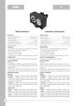
- HIDDEN COMMAND = Positioned under
the 6 commands, to the centre between
Advance and Volume/Clock, it allows to
start a regeneration test (1 min. phases).
When pressed for a few moments of the
programming, resets the flashing figure
on the display.
3 - GENERALITY
Below-mentioned are some indications
that must be respected during the use
and the maintainance of the controller
in order to guarantee its long operational
life.
3.1 – Packaging and storage
The packaging is composed of a box
with a label which identifies the product.
The storage of the device must be in
environments with the following
characteristics: - inclusive temperature
between +4°C and +40°C; - relative
damp between 30% and 95%.
3.2 – Installation
The installation of the controller must be
effected by qualified personal; the
procedures of installation must be
per formed with the controller
disconnected from power supply. The
controller is composed of a box in ABS,
closed frontally from a plate fixed with 4
screws and protected with a transparent
cover. The controller is powered with a
transformer 230 / 12 Vac. Other type of
transformers are available on demand.
(Es. 115 / 12 Vac – 60 Hz). If the Aqua
Timer is in the Chronometric version, the
right side of the box is opened in
correspondence of the plug DIN 180º (Fig.
16). If the Aqua Timer is in the Volumetric
version, on the back side of the box there
is the cable of the the water meter cable
that must be inserted in the special
lodging on the valve or on the SIATA
turbine (Fig. 17).
Fig. 3
compatibility). For the installation of the
timer on the valve, when it has the pilots
connected to the controller (valve 132)
as shown in the following photos, proceed
as follows:
Fig. 5 – The valve in the package has the
piston inserted into the pilot piston, and
the screw is inserted in its lodging.
Fig. 5
Fig. 6 – Unscrew the screw and pull both
pistons up to the suit position.
Fig. 6
Fig. 7 – On the extreme part of the pilot
piston there is a flat part with two arrows.
Insert the edge of the cam on the inclusive
space between such arrows. Make sure
that the pilot pistons are moved outwards
in order to position the edge of the cam
in the better way.
Fig. 7
Fig. 4
In case you desire to supply the external
pilots of the controller (Fig. 3 and 4) with
compressed air, you have to verify that:
• the pressure of the air of command is
between 1 and 6 atm, and, in any case
it can’t be superior to the pressure of the
inlet water;
• the line of the air of command is fitted
with an humidifier of the air (with water
or suitable lubricating), in order not to
cause the desiccation of the pilot gaskets;
If the pilots are supplied with water, a
filter in the inlet side is needed against
the impurities.
It is advised to set
particular attention in the installation of
the controller in environments that are
not conforming to the limits listed in the
norm EN 50082-1 (electromagnetic
Fig. 8 – Push the timer toward the valve
so that the pistons enter inside the pilot
pistons and the two teeth of fixing points
shown in Fig. 7 go to insert in the
dedicated lodgings.
Fig. 8
341