1
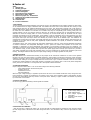
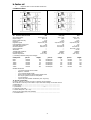
K-FACTOR SRL
Stabilizzatori di tensione trifase
elettromeccanici
Serie RTC – RTC/220 - RTI
Istruzioni per l’uso e la manutenzione
Three phase electromechanical
voltage stabiliser
RTC – RTC/220 - RTI range
Directions for use and maintenance
Nota: Questo manuale si riferisce al modello per tensione di rete 400V+N. Per altri paesi, con le medesime
caratteristiche, gli stabilizzatori sono fornibili con tensione di rete 380V o 415V o altre a richiesta. Controllate
che la tensione nominale dell’apparecchio corrisponda a quella del paese dove viene installato.
Warning: this handbook refers to the model for network voltage of 400V+N. For other countries, under the same
characteristic, stabilisers are supplied with rated voltage 380V or 415V. Check that the rated voltage on the
plate of the apparatus is conforming to the country network one and to the installation of the stabiliser.
k-factor srl
INDICE
1. Generalità
2. Principio di funzionamento
3. Caratteristiche elettriche
4. Comandi e strumentazione
5. Istruzioni per l'installazione
6. Norme particolari per serie RT "triangolo" 230V
7. Norme per un corretto utilizzo - Manutenzione
8. Intervento di pulizia dei variatori
9. Schema di principio
10. Dati tecnici
11. In caso di assistenza
RTC
RTI
RTC
RTI
RTC
RTI
RTC
RTI
1. GENERALITÀ
Gli stabilizzatori trifase elettromeccanici della serie RTC sono del tipo elettromeccanico a controllo elettronico con regolazione
indipendente della tensione di uscita su ogni fase, caratteristica assolutamente necessaria in presenza di carichi fortemente
squilibrati: utilizzano, infatti, tre circuiti di comando e tre servomotori, in modo da poter stabilizzare ciascuna fase
indipendentemente dalle altre. Questa peculiare caratteristica e l'elevata affidabilità rendono gli stabilizzatori della serie RTC
adatti ad operare in qualsiasi condizione in cui sia necessaria una tensione rigorosamente vicina al valore nominale. Gli
stabilizzatori trifase della serie RTC sono montati in armadio metallico, sono particolarmente silenziosi e assolutamente privi di
dispersione magnetica, non introducono distorsioni armoniche. Per un corretto collegamento è bene ricordare che il neutro deve
essere accessibile ed il collegamento in uscita avviene sempre a stella. Se lo stabilizzatore è abbinato in ingresso ad un
trasformatore, il collegamento in entrata può essere effettuato a stella o a triangolo, anche senza neutro.
Gli stabilizzatori della serie RTI accomunano a tutte le caratteristiche della serie RTC i vantaggi dell’abbinamento con un
trasformatore trifase di isolamento, posto a monte dello stabilizzatore stesso. Gli indiscussi vantaggi di tale abbinamento si
riassumono in alcune garanzie essenziali: la separazione totale della rete con l’eliminazione o l’attenuazione dei disturbi sulla
stessa e la protezione di tutte le apparecchiature a valle dello stabilizzatore, la possibilità di collegare a terra il neutro in uscita
supplisce infine alla mancanza del neutro in entrata, indispensabile per il funzionamento di uno stabilizzatore della serie RT. Per
ultimo, nelle zone dotate solo di tensione 230V trifase senza neutro, permette di ottenere una tensione a 400V trifase
stabilizzata con neutro accessibile. Gli stabilizzatori della serie RTI sono dotati di un interruttore automatico quadripolare, tre
voltmetri digitali in grado di fornire il valore della tensione in entrata ed in uscita, di una morsettiera per il collegamento alla rete
ed al carico che facilità notevolmente l’installazione.
2. PRINCIPIO DI FUNZIONAMENTO
Le serie RTC-RTI utilizzano, per la regolazione di ogni fase, il principio del trasformatore "serie". Un variatore, regolato tramite
un circuito di comando in base alla tensione di uscita risultante, alimenta un trasformatore il cui secondario è posto in serie sulla
fase. La tensione che scaturisce dal secondario del trasformatore va a sommarsi o a sottrarsi alla tensione di ingresso. La lettura
continua della tensione di uscita permette al circuito di comando di fornire un impulso di rotazione al motore in c.c. che regola
la tensione di uscita del variatore. Ogni modulo di fase è collegato agli altri due con una configurazione circuitale a "stella" che
comporta l'utilizzo del neutro in ingresso e la disponibilità dello stesso sull'uscita, come riportato nello schema 1. La serie RTI è
composta da uno stabilizzatore della serie RT e da un trasformatore di isolamento di potenza adeguata.
3. CARATTERISTICHE ELETTRICHE
Di seguito sono citate le caratteristiche elettriche degli apparecchi stabilizzatori.
La tensione di uscita è mantenuta costante entro il ±1% del valore nominale nelle seguenti condizioni:
- tensione compresa tra 340V e 460V trifase
- frequenza 50-60Hz
- carico compreso tra 0 e 100%
Quando varia la tensione di ingresso, un impulso di regolazione muove la spazzola del variatore che, attraverso il trasformatore
serie, aggiunge o sottrae diversi valori di tensione per rientrare nell'errore stabilito. La velocità di regolazione è stimata in ca.
20msec. per ogni Volt da regolare. Gli stabilizzatori della serie RTC-RTI non risentono delle variazioni del fattore di potenza
(cos-phi) del carico. Il rendimento a pieno carico è ca. il 94%-98% secondo i modelli. Lo stabilizzatore è protetto da un
interruttore magnetotermico quadripolare di portata adeguata.
4.
COMANDI E STRUMENTAZIONE
Sul pannello superiore sono presenti:
a.
b.
c.
d.
e.
f.
2
Voltmetro digitale
Commutatore
lettura
voltmetro
ingresso-uscita
Commutatore lettura voltmetro su ogni
fase e lettura tensione concatenata
Trimmer regolazione fine della tensione
in uscita per ogni fase
Interruttore automatico di protezione
Lampada spia di funzionamento
k-factor srl
RTC
RTI
RT
RTI
RT I
230V
RTI
RT
RTI
5.
ISTRUZIONI PER L'INSTALLAZIONE
Aprire il portello frontale utilizzando la chiave fornita, assicurandosi che l’interruttore sia abbassato.
Sul lato destro sono posti due pressacavi per il passaggio dei cavi di entrata e uscita (per la serie RTI l’ingresso cavi è dal basso
o dai lati aprendo i lati dello zoccolo). Inserire il cavo di entrata in un pressacavo.
Lo stabilizzatore è provvisto di una morsettiera di collegamento così composta:
nr. 4 morsetti denominati R,S,T,N per ingresso
nr. 4 morsetti denominati R,S,T,N per uscita
nr. 1 o 2 morsetti di terra
Collegare la tensione di rete ai morsetti denominati "ingresso" rispettando la successione delle tre fasi (R,S,T) e neutro (N).
ATTENZIONE: IL COLLEGAMENTO DEL NEUTRO IN INGRESSO ALLO STABILIZZATORE È ASSOLUTAMENTE NECESSARIO, ANCHE SE NON
RICHIESTO DAL CARICO.
Attenzione: il collegamento del NEUTRO in ingresso dipende dalla configurazione richiesta per il trasformatore di isolamento
posto a monte dello stabilizzatore trifase. Il trasformatore è fornito di serie con collegamento triangolo-stella (gruppo vettoriale
Dyn) come riportato nello schema 2 allegato. In questo caso collegare soltanto le fasi R.S.T. Non sarà presente in ingresso il
morsetto N (neutro) perché non necessario.
Nel caso il Vs. apparecchio appartenga alla serie RTI stabilizzatore trifase con trasformatore d’isolamento con ingresso 230V
trifase senza neutro e uscita 400V, collegare le tre fasi R, S, T ai morsetti denominati “ingresso”. Anche in questo caso non è
presente in ingresso il morsetto N (neutro).
Attenzione: non intervenire mai sui morsetti di collegamento del trasformatore di isolamento. I collegamenti relativi al
trasformatore sono già effettuati e non devono essere modificati. I morsetti utilizzati non devono essere utilizzati per i
collegamenti in entrata o uscita.
Dopo avere inserito il cavo di alimentazione del carico nel secondo passacavo, collegare le fasi ai morsetti denominati “uscita”
rispettando la successione delle tre fasi (R, S, T) e neutro (N). Collegare la terra in ingresso e uscita ai morsetti di terra
dell’apparecchio.
SE SONO COLLEGATI CARICHI MONOFASE E’ SEMPRE CONVENIENTE DISTRIBUIRLI EQUAMENTE SULLE TRE FASI. AD OGNI FASE (R, S,
T) POSSONO ESSERE COLLEGATI CARICHI MONOFASE NEI LIMITI DI UN TERZO DELLA POTENZA RESIDUA, UNA VOLTA COLLEGATE LE
UTENZE TRIFASE.
Es. Stabilizzatore trifase RT22K – 22KVA
Potenza massima disponibile:
Utenza 1- Trifase 400V 10KVA
Potenza residua
Disponibili su ogni fase (R, S o T)
RT
RTI
22.000VA –
10.000VA =
-------------------12.000VA
12.000VA : 3 = 4.000VA
Bloccare i cavi di ingresso-uscita con i pressacavi. Richiudete il portello frontale e sollevate l’interruttore magnetotermico.
L’accensione dello stabilizzatore deve sempre avvenire con le utenze spente. Accendete il carico, e verificate, tramite
una pinza amperometrica, che la potenza assorbita sia inferiore alla potenza di targa dello stabilizzatore. Effettuando una misura
per ogni fase, la potenza assorbita non deve superare un terzo della potenza di targa dello stabilizzatore. Un eventuale squilibrio
del carico anche del 100% è perfettamente tollerato dallo stabilizzatore purché la potenza assorbita su ogni fase non superi un
terzo della potenza di targa.
Verificate per ogni fase, agendo sui commutatore voltmetrico IN-OUT e sul commutatore di fase posti sul pannello frontale, che
la tensione d’ingresso sia entro i limiti di targa dell’apparecchio. Ricordate che il voltmetro indica la tensione di fase, prelevata
tra fase e neutro, in altre parole la tensione di targa diviso 1,73. Se la tensione trifase è 400V, i voltmetri indicheranno in
ingresso e uscita una tensione (nominale) di 230V. Quando il commutatore è posto in posizione IN, il voltmetro indica la
tensione di ingresso. Tale tensione non deve superare i limiti -15%+15% della tensione nominale. Nel caso di tensione trifase
400V, i limiti sono da 195V a 264V. Quando il commutatore è in posizione OUT, il voltmetro indica la tensione di uscita. Tale
tensione non deve eccedere l’errore del ±1%, non deve variare quindi oltre le tensioni 228/232V. Lo stabilizzatore RT-RTI è
dotato di tre viti di regolazione “OUT CONTROL” che consente di effettuare la taratura precisa dell’apparecchio per ogni fase.
Tale taratura deve essere effettuata soltanto la prima volta, dopodiché resta fissa fino ad una nuova regolazione. Si può
decidere di prelevare una tensione diversa da quella nominale entro i limiti del ±5%, regolando la vite “OUT CONTROL” anche
per una singola fase. Ricordate tuttavia che, tarando l’apparecchio su una tensione inferiore, la potenza disponibile diminuisce
della stessa percentuale. Lo stabilizzatore è pronto ad entrare in esercizio.
6.
NORME PARTICOLARI PER SERIE RT TRIANGOLO – 220 O 230V
Nel caso abbiate acquistato uno stabilizzatore trifase in configurazione "/220" o “/230” per reti non dotate di neutro, il
collegamento in entrata e uscita e tutte le regolazioni vanno effettuate allo stesso modo, ricordando le seguenti avvertenze:
I
I morsetti di ingresso e uscita sono privi del morsetto N (neutro). Il collegamento del neutro non è previsto né è
necessario per il funzionamento dell'apparecchio.
II
I voltmetri in entrata e uscita leggono le tensioni tra fase e fase: RS-ST-RT. Dovranno pertanto indicare, in caso di
corretto funzionamento, 230V ±15% in ingresso, 230V ±1% in uscita.
7.
NORME PER UN CORRETTO UTILIZZO - MANUTENZIONE
1.
Lo stabilizzatore non deve operare in ambienti polverosi o in presenza di agenti chimici corrosivi.
2.
Non pulire mai la superficie dell'apparecchio con prodotti aggressivi. Non usare olio o solventi chimici.
3.
Non utilizzare mai l'interruttore magnetotermico dello stabilizzatore come interruttore generale dell'apparecchio
utilizzatore. Tale operazione, se ripetuta nel tempo, può a lungo andare danneggiare l'apparecchio.
4.
Alcuni modelli sono dotati di ventole di raffreddamento. Prestate attenzione a non coprire tali ventole per evitare
l'eccessivo riscaldamento dell'apparecchio. Non appoggiare oggetti, libri o altro sul coperchio dello stabilizzatore, evitando
inoltre di collocarlo vicino a fonti di calore.
5.
Se vengono rispettate con cura le norme precedenti, lo stabilizzatore non richiederà interventi di manutenzione per
diversi anni. E' bene, saltuariamente, verificare che su ogni fase la tensione venga regolata correttamente, controllando le
tensioni in entrata e uscita.
8.
INTERVENTO DI PULIZIA DEI VARIATORI
Può essere necessario, con una periodicità di 30-36 mesi, effettuare una pulizia dei variatori. Per effettuare tale operazione
seguire le seguenti indicazioni:
1.
Scollegare lo stabilizzatore dalla rete
3
k-factor srl
2.
Svitare le viti dei tre pannelli frontali di fase e staccare il connettore degli strumenti
3.
Portare lentamente a fine corsa il braccetto con la spazzola del variatore spostandolo con la mano
4.
Utilizzando carta vetrata molto fine pulire la superficie di contatto con la spazzola, fino a quando la grafite e la polvere
depositate non siano eliminate
5.
Spostare leggermente il braccetto delle spazzole per pulire anche nel punto di fine corsa. Verificare, ruotando
lentamente il braccetto con la mano, che il percorso della spazzola sia regolare e privo di asperità.
6.
Effettuare la stessa operazione per le altre fasi e richiudere l'apparecchio.
9.
SCHEMA DI PRINCIPIO
Modelli RTC/RTI con neutro
10. DATI TECNICI
Tensione nominale entrata
Tensione di uscita
Precisione della tensione di uscita
Frequenza
Tempo di risposta
Fattore di potenza del carico
Variazione accettabile del carico
Distorsione armonica introdotta
Soppressione picchi di tensione
Attenuazione disturbi
Squilibrio ammesso dal carico
Rendimento a pieno carico
Temperatura
(* a seconda delle potenze)
Modelli RTC senza neutro (serie “RTC/220”)
serie RTC
400V ±15% + N
400V + N
±1%
50-60Hz
20 millisec. per Volt
qualsiasi
da 0 a 100%
inferiore all'1%
------qualsiasi
94-98%*
-10°C +40°C
serie RTC/220
220V ±15%
220V
±1%
50-60Hz
20 millisec. per Volt
qualsiasi
da 0 a 100%
inferiore all'1%
------qualsiasi
94-98%*
-10°C +40°C
Potenza nom.
Codice ord.
Peso Kg.
Codice ord.
Peso Kg.
6KVA
RTC06K
85
RTC06K/220
90
9KVA
RTC09K
88
RTC09K/220
95
12KVA
RTC12K
94
RTC12K/220
120
15KVA
RTC15K
96
RTC15K/220
135
22KVA
RTC22K
120
RTC22K/220
190
30KVA
RTC30K
126
RTC30K/220
250
Dotazione:
interruttore automatico quadripolare
voltmetro digitale
commutatore per l'indicazione in-out del voltmetro
commutatore per la lettura della tensione su ogni fase e della tensione concatenata
regolazione fine della tensione per ogni fase
morsettiere per il collegamento alla rete e al carico
trasformatore d’isolamento ( solo per la serie RTI )
serie RTI
400V± 15%
400V + N
±1%
50-60Hz
20 millisec. per Volt
qualsiasi
da 0 a 100%
inferiore all'1%
fino a 6kV a 100J
> 40 dB
qualsiasi
94-98%*
-10°C +40°C
Codice ord.
RTI06K
RTI09K
RTI12K
RTI15K
RTI22K
RTI30K
Peso Kg.
102
116
134
156
198
216
11. IN CASO DI ASSISTENZA
La ditta confida in una completa collaborazione della Clientela al fine di migliorare il proprio servizio. Pertanto ricordiamo alcuni
dati da riconoscere prima di interpellare il ns. servizio tecnico:
a. Modello della macchina ....................................................................................................................................
b. Numero di matricola ........................................................................................................................................
c. Acquistato da.......................................................... il ....................................................................................
d. Tipo di carico...................................................................................................................................................
e. Assorbimento inserito.......................................................................................................................................
( rilevabile sulle targhe di caratteristiche degli apparecchi)
f. Difetto riscontrato ............................................................................................................................................
In caso di restituzione per riparazione, allegare sempre alla macchina una lettera citando i dati richiesti, insieme all'imballo
originale ed in PORTO FRANCO.
4
k-factor srl
Index
1. General data
2. Working principle
3. Technical specification
4. Controls and signals
5. Instructions for the installation
6. Rules for RTC "delta" 230V
7. Rules for a proper use - maintenance
8. Cleaning of the variable transformers
9. General scheme
10. Technical data
11. In case of assistance
1. General data
The RTC series electromechanical stabilisers with electronic control, with independent output voltage regulation for each phase,
are an essential feature for highly unbalanced loads. The stabilsers use three control circuits and three servo-motors, so that
each individual phase may be stabilised independently from the others. This special feature together with a high degree of
reliability make the RTC series ideal for use in any applications requiring that the voltage is maintained rigorously constant near
the rated value. RTC stabilisers are mounted on a moveable rack; they are exceptionally quiet runninng, totally free from
magnetic leakage, and do not introduce harmonic distorsion. All models are equipped with an anti-disturbance device to
attenuate line noise and voltage peaks. For correct connections, the neutral should always be accessible and the output
connection must always be in star configuration. If the stabiliser is used in combination with an input transformer, the input
connection may be made in either star or delta configuration, also without the neutral. On request, a stabiliser is available with
three phase 230V input and output without the necessity to provide a neutral at the stabiliser input. RTC stabilisers are
equipped with an automatic 4-pole switch, three digital voltmeters for input and output voltage readings, and terminal strip for
connection to the mains and the load, which significantly simplifies installation. On request, all models are available with
insulation transformer.
The stabilisers of the "RTI" range combine the performance characteristic of the "RT" range with the advantages provided by
an isolation transformer. The indisputable advantages of such a system are evident: total separation of the mains with
elimination or attenuation of mains disturbances and protection of all equipment protected by the line conditioner. The
possibility to connect the output neutral to earth compensates the absence of input neutral, indispensable for the functioning of
"RT" stabilisers. Finally, in areas provided with only 220V three phase supply without neutral, upon request "RTI" provides a
400V (380V) regulated power supply with accessible neutral. "RTI" line conditioners are equipped with automatic 4-pole circuit
breaker, three digital voltmeters with input and output voltage reading, fine voltage regulation for each phase.
2. Working principle
RTC-RTI stabilisers are manufactured according to the principle of the “buck-boost” transformer. A control circuit regulates
through a DC motor the output voltage of a variable transformer, which supplies a “buck-boost” transformer whose secondary
winding is connected in series to the line voltage. The output voltage of the transformer increases or decreases the line voltage.
The continuous reading of the output voltage allows the control circuit to give a rotation command to the DC motor which
regulates the variable transformer. Each phase module is connected to the following with a “star” three phase configuration
circuit, as shown on scheme No.1. RTI range has also a three phase isolation transformer.
3. Technical specification
Output voltage is constant within a ±1% on the rated voltage in the following conditions:
Input voltage between 340-460V three phase
Frequency 50-60 Hz
Load between 0:100%
Any load unbalancce
When the input voltage changes, a regulation impulse move the brush of the variable transformer which, through the buckboost transformer, increases or decreases the line voltage of the correct value. Regulation speed is approximately 20/1000
Sec./Volt. RTC-RTI stabilisers allow any variation of the power factor. Efficiency is approx. 94-98%. The stabiliser is protected
by an automatic circuit breaker.
4. Controls and signals
On the front (up) panel the following controls-signals are available:
a.
b.
c.
d.
e.
f.
Digital voltmeter
In-Out voltage reading switch
Phase reading switch
Fine voltage regulation for
each phase
Automatic circuit breaker
Mains lamp
5. Instruction for installation
- Open the front door, checking the switch is off. On the right side two cable glands are provided for input and output cables
(for RTG range access is allowed from the sides through the base or from the bottom side). Insert the input cable in a cable
gland.
5
k-factor srl
- The stabiliser is provided with a terminal board consisting in:
a) four terminals marked R,S,T,N for input
b) four terminals marked R.S.T.N, for output
c) one or two earth terminals
- Connect the line voltage to the terminals marked "INPUT" respecting the succession of the three phases (R,S,T) and neutral
(N)
Warning: the connection of the neutral on the input of the stabiliser is necessary even if not requested by the
load
Warning: in the RTI range the connection of the neutral on the input side depends from the required connection
of the Isolation transformers connected to the stabiliser. The isolation transformer is usually supplied with a
delta-wye configuration (Dyn11 vector group) –in this case input “N” terminal will not be present- but a
different connection may be required. Please check the label of the Isolation transfomer in your stabiliser for
more information
If you purchased the “RTI” stabiliser with input isolation transformer 230Vac/400Vac, connect the input cables to the R-S-T to
the input connectors. In this case connection of the neutral is still not necessary.
Warning: in the RTI range never change the connections of the isolation transformer. Isolation transformer is
already connected to the stabiliser. Input-output connectors of the transformer must not be used for inputoutput connections of the stabiliser
If single phase equipments are connected, it is always advisable to connect the loads equally on the three lines.
Single phase loads up to 1/3 of the residual available power of the stabiliser can be connected to each phase,
once considered the three phase loads
Eg. Three phase stabiliser RTC22K
Max power available:
Load # 1- Three phase 400Va.c. 10KVA
Residual power
Available power on each phase (R, S or T)
22.000VA –
10.000VA =
-------------------12.000VA
12.000VA : 3 = 4.000VA
- Connect the feeding line of the load/s to the terminals marked "OUTPUT" respecting the succession of the three phases
(R,S,T) and neutral (N)
- Close the fron door and turn on the circuit breaker (always with loads OFF)
After the stabiliser is on, turn the loads on, check that the power requested by the loads is lower than the rated power of the
stabiliser. For this operation use an A-meter to meausre the current on each phase. The current on each phase must not
exceed one third of the rated current of the stabiliser.
- The voltmeter shows for each phase the input or the output voltage according to the position of the below switch "IN" or
"OUT" and the “R-S-T phase” switch.
- The "OUT CONTROL" screws allow to obtain a fine regulation of the voltage of each phase.
For each phase verify that the input voltage is in the acceptable range. Input voltage can be displaied using the IN-OUT switch
and the R-S-T- phase switch. Remember that the Voltmeter shows the phase voltage between phase and neutral; it means
that, for a rated voltage of 400Va.c. three phase, the voltage will display 230V for each phase (approx. 400/1,73). The standard
acceptable input range is ±15% of the rated voltage. If the voltage is 400V, acceptable range is (for each phase) from 195V up
to 264V. When the swith is in OUT position, the voltmeter shows the output voltage. The output voltage must nox exceed the
limit of ±1% of the rated voltage (please also consider that each voltmeter can measure with a tolerance of ±0.5% ± 1 digit).
The voltage must not exceed the renge between 228V and 232V in the 400V models. RTC and RTI stabilisers are provided with
three fine voltage regulation screw, which allow an acurate regulation of the output voltage. This regulation is normally made
by the factory, but it can be done also by the user if any factor changes this regulation. It is advisable to do this regulation only
at the first use. User cna decide to regulate the stabilised voltage to a voltage different from the rated one. Through the
regulation screws it is possible to regulate the output stabilised voltage up to a ±5% of the rated voltage. Please note that
regulating the output voltage to a lower level, output total power decreases proportionally.
Now the stabiliser is ready for the use
6. RULES FOR RTC DELTA-230V OR 220V (T-MODELS)
If you purchased a three phase stabilisers in “Delta” (T) configuration for networks without the neutral please remember that:
I
In-Out connectors do not have a “Neutral” connector. “Neutral” is not provided and is not necessary for the use of the
stabiliser
II
In-Out voltmeters will read the “Phase to phase” voltage. In the case of the 230V rated voltage, the voltmeter will
read 230V
7. RULES FOR A PROPER USE - MAINTENANCE
1.
The stabiliser must not operate in dusty areas
2.
Never clean the surface of the equipment with strong claning products, do not use oil.
3.
Never use the automatic circuit breaker as a main circuit breaker. On the long term this may damage the
stabiliser
4.
Some models are fitted with cooling fans. Do not cover the fans. Do not place anything on the cover of the
stabiliser, do not place it close to any heating source
5.
If these rules are respected, the stabiliser will not require maintenance interventions for many years of
operation. It is useful to chack regularly input and output voltage to prevent any damage to your equipmaent in
case of a failure of the stabiliser.
8. CLEANING OF THE VARIABLE TRANSFORMERS
Every 30-36 months a cleaning of the variable transformers could be necessary.
1.
Turn off the stabiliser.
2.
Open the front door of the stabiliser
3.
Rotate the brush to an end manually
4.
Carefully clean the surface with abrasive paper, until graphite and dust are removed.
5.
Rotate the brush on reverse to the second end and clean the part previously covered by the brush. Verify,
rotating the brush, that the surface is clean and flat.
6
k-factor srl
6.
Repat the same on all the variable transformers
9. GENERAL SCHEME
RTC/RTI TYPE WITH NEUTRAL
RTC/RTI TYPE WITHOUT NEUTRAL (T-MODELS)
10. TECHNICAL SPECIFICATION
RTC
Input rated voltage
400V ±15% + N
Output voltage
400V + N
Output voltage accuracy
±1%
Frequency
50-60Hz
Regulation speed
20/1000 sec/ Volt
Load acceptable power factor
any
Acceptable load variation
da 0 a 100%
Harmonic distortion
less than 1%
Surge suppression
---Attenuation
---Tolerable load unbalance
qualsiasi
Full load efficiency
94-98%*
Ambient temperature
-10°C +40°C
(* according to different ratings and voltages)
rated power
6KVA
9KVA
12KVA
15KVA
22KVA
30KVA
part no.
RTC06K
RTC09K
RTC12K
RTC15K
RTC22K
RTC30K
weight
85
88
94
96
120
126
part no.
RTC06K/220
RTC09K/220
RTC12K/220
RTC15K/220
RTC22K/220
RTC30K/220
RTC/220
220V ±15%
220V
±1%
50-60Hz
20/1000 sec/ Volt
any
da 0 a 100%
less than 1%
------qualsiasi
94-98%*
-10°C +40°C
weight
90
95
120
135
190
250
Standard accessories
(3) 4 poles automatic circuit breaker
digital a.c. voltmeter
in-out voltmeter display switch
phase to N and phase to phase voltage display switch
fine output regulation screws on each phase
In-out connectors
Input three phase isolation transformer (RTI range only)
11. IN CASE OF ASSISTANCE
In order to improve our service we trust in customers’ full co-operation.
We would like to remind you some data to report herein before calling our technical service:
A- Model/Part No. ......................................................................................................
B- work number ........................................................................................................
C- purchased by ............................................................on........................................
D- computer or load type ............................................................................................
E- inserted absorption (W or VA) ...............................................................................
(shown on the rating plate of the stabiliser)
F- remarked defect .....................................................................................................
7
RTI
400V± 15%
400V + N
±1%
50-60Hz
20/1000 sec/ Volt
any
0 : 100%
less than 1%
fino a 6kV a 100J
> 40 dB
qualsiasi
94-98%*
-10°C +40°C
part no.
RTI06K
RTI09K
RTI12K
RTI15K
RTI22K
RTI30K
weight
102
116
134
156
198
216
k-factor srl
“RT” Range Stabilisers : TROUBLE-SHOOTING PROCEDURE
PROBLEM NO. 1
The output voltage is unstable compared with the fixed value or, rotating the fine regulation knob, the output
voltage does not change accordingly.
SOLUTION:
Check if the variable transformer’s brushings are worned out or are sticked.
If positive:
Clean the road on that the brushings run
Check their wear’s state and eventually replace them
Check the correct working of the micro-motor to avoid slidind between shaft and join
If negative:
Replace the control electronic card
PROBLEM NO. 2
The voltmeter marks “000” or it is turned off
SOLUTION:
Check the 3 supply wires are strictly solded and that the voltage supply is +5V
Replace the electronic card
PROBLEM NO. 3
The output voltage is “0V” in one or more phases
SOLUTION:
Check the input voltage of each phase. The voltage must be between the nominal limits of the stabiliser.
Check the proper connection of the series transformers
Check the efficency of the circuit breaker
Note:
Even in presence of failure of the board, provided that the above points are properly checked, an output voltage can be
measured.
8
k-factor srl
GARANZIA
L'apparecchio come ogni suo componente è stato sottoposto ad accurati collaudi ed è garantito per un periodo di 12 mesi dalla
data di acquisto o non oltre 13 mesi dalla data di spedizione. Per data di acquisto si intende quella indicata sulla fattura o
ricevuta fiscale rilasciata dal venditore. La garanzia sulle parti elettroniche si intende prolungata a mesi 24. Per garanzia si
intende la sostituzione o riparazione gratuita dei componenti riconosciuti dalla ditta produttrice inefficienti o difettosi di
fabbricazione. Per l'intervento in garanzia, l'apparecchio deve essere consegnato o inviato franco di porto al servizio di
assistenza più vicino, allegando lettera con dati apparecchiatura descritti nel paragrafo precedente. Il trasporto avverrà a rischio
e pericolo dell'acquirente. L'apparecchio riparato in garanzia verrà restituito all'acquirente appena possibile e a sue spese e
rischio. Sono escluse dalla garanzia le rotture accidentali, distruzioni o folgorazioni da eventi naturali, i danni provocati da
incuria, uso ed installazione errati, impropri o non conformi alle avvertenze riportate. La garanzia decade qualora l'apparecchio
sia stato manomesso o riparato da personale non autorizzato o abbia subito interventi per vizi o verifiche di comodo. E' esclusa
la sostituzione dell'apparecchio o il prolungamento della garanzia in caso di intervento. E' escluso altresì il risarcimento di danni
diretti o indiretti di qualsiasi natura a persone, cose o animali per l'uso e la sospensione d'uso dell'apparecchio.
GUARANTEE
This guarantee is offered as an extra benefit and does not affect your legal rights.
All the voltage stabilisers and line conditioners are guaranteed by the Company for one year against faulty material or
workmanship. If any part is found to be defective in this way within the first twelve months from the purchase date, we or our
authorised service agents, we will replace or at our option repair that part without any charge for materials or labour, provided
that the appliance has been used only in accordance with the instruction provided with each stabiliser and that it has not been
connected to an unsuitable electricity supply, or subjected to misuse, neglect or damage or modified or repaired by any person
not authorised by us.
The correct electricity supply voltage and frequency is shown on the rating plate on the appliance. This guarantee is normally
available only to the original purchaser of the appliance, but the company will consider written applications for transfer.
Should any defect arise in any voltage stabilisers or line conditioners a claim under guarantee become necessary, the appliance
should be carefully packed and returned to your local service agent. This copy of the guarantee should be attached to the
appliance. Guarantee is applied only if the equipment is returned F.O.T. our factory. No technical intervention may be claimed
for any reason at the place of installation under guarantee.
Cut and send to our address for the validity of the guarantee
Model/type
Tagliare e inviare in busta chiusa per la validità della garanzia
Modello
Work no.
No. Matricola
Manuf. Year
Anno fabbricazione
Tested by
Firma collaudo
Data di acquisto/Purchase date: _______________
Nome e indirizzo dell’acquirente/Name and address of the owner:
(Inviare entro 15 gg. dalla data di acquisto/to be sent within 15 days from the purchase date)
9