1
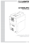
HALUSTRIP
5
1.3 OPERATING ELEMENTS AND CONNECTIONS
2
4
10
FUSE
POWER IN
11
6
DMX IN
1
7
8
MENU
UP
ENTER
DOWN
DMX IN
DMX OUT
9
DMX OUT
5
POWER OUT
3
Rear panel
Fig.1
1. MOUNTING BRACKET
2. LOCKING KNOB for the mounting bracket
3. CONTROL PANEL with display and 4 button
used to access the control panel functions
and manage them
4. POWER IN (PowerCON IN): for connection to a
socket (100-240V~/50-60Hz) via the supplied
mains cable.
5. POWER OUT (PowerCON OUT): connect to
supply power to the next unit
6. DMX IN (3-pole XLR):
1 = ground, 2 = DMX -, 3 = DMX +
7. DMX IN (5-pole XLR):
1 = ground, 2 = DMX-, 3 = DMX+, 4 N/C, 5 N/C
8. DMX OUT (3-pole XLR):
1= ground, 2 = DMX -, 3 = DMX +
9. DMX OUT (5-pole XLR):
1 = ground, 2 = DMX-, 3 = DMX+, 4 N/C, 5 N/C
10. FUSE OLDER in the event of breakage, always
replace the fuse with the same type and
rating (T2A/250V).
11. GND POINT grounding the fixture to the earth