1
CHAPTER 3: Installation
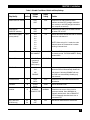
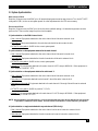
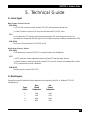
Table 1. Printed Circuit-Board Switch and Strap Settings
Possible
Settings
Factory
Setting
MAIN DCE/DTE switch
DTE
DCE
DTE
Determines the PSD’s Main Channel
interface as either DTE (straight connection
to a modem) or as DCE (straight connection
to a computer or terminal).
Sub-channel
DCE/DTE switches
DTE
DCE
DTE
Determines the PSD’s sub-channel interface
as either DTE or DCE.
19.2
14.4
9.6
7.2
4.8
2.4
1.2
CLK 1
9.6
Stap Identity
DATA RATE (kbps)
(rotary switch)
Location
BR1
Function
Selects the PSD’s internal data rate or external
clock from sub-channel 1.
NOTE: When using CLK 1 mode, the main
channel cannot be connected to a modem
working in internal clock.
Chas. GND
J1
CONNECT
DISCONNECT The CONNECT setting connects signal ground
DISCONNECT
to chassis ground. The DISCONNECT setting
isolates them.
PIN 24 DIS
J1A
ENABLE
(jumpered)
DISABLE
(NO jumper)
ENABLE
Exits main channel when PIN 24 is disabled.
TIME OUT
J2
1.7
13.5
108
DISABLE
108
Selects the time-out period (in seconds) after
which the PSD will automatically disable the
sub-channel. Selecting DISABLE will stop
the PSD from automatically disabling any
sub-channels.
CONTENTION
J5
RTS
DATA
RTS
Determines the sub-channel selection and
deselection.
FORMAT
J6
ASYNC
SYNC
SYNC
CLOCK
J7
NORMAL
FROM EXT DTE
NORMAL
EXT. BUFFER
(PSD-8 only)
S1
S2
ON
OFF
OFF
Selects the data format.
Determines the source of the clock for
synchronous data. Set to NORMAL for
internally derived clock. Set to FROM EXT
DTE for externally dermined clock from a
connected DTE.
Activates or deactivates the extra buffer.
7