1
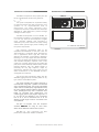
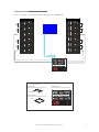
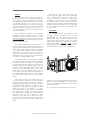
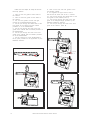
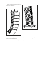
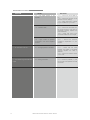
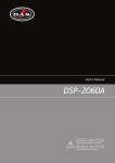
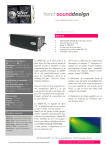
User's Manual
aero 12
Antes de utilizar el equipo, lea la sección
“Precauciones de seguridad” de este
manual. Conserve este manual para
futuras consultas.
Before operating the device, please read
the “Safety precautions” section of this
manual. Retain this manual for future
reference.
CONTENTS
SAFETY PRECAUTIONS
3
WARRANTY
4
DECLARATION OF CONFORMITY
5
SYSTEM DESCRIPTION
6
LINE DRAWINGS
6
CONNECTION
7
SPECIFICATIONS
8
CONFIGURATION
9
RIGGING SYSTEM
10 to 13
14
TROUBLESHOOTING
Manual del Usuario / aero 12 / User’s Manual
æro 12
Precauciones de Seguridad
Safety Precautions
Caja acústica pasiva / Passive loudspeaker enclosure
El signo de exclamación dentro de un triángulo indica la
existencia de importantes instrucciones de operación y
mantenimiento en la documentación que acompaña al producto.
Conserve y lea todas estas instrucciones.
Siga las advertencias.
The exclamation point inside an equilateral triangle is intend to
alert the users to the presence of important operating and
maintenance (servicing) instructions in the literature
accompanying the product.
Heed all warnings. Follow all instructions.
Keep these instructions.
El doble cuadrado indica equipo de Clase II.
The double square indicates Class II device.
Las especificaciones se encuentran en la etiqueta de la parte
posterior del producto.
The specifications can be found on the rear label of the product.
Equipo IP-33 según la norma IEC 60529:1989 + M1 @ 1999
IP-33 equipment (IEC 60529:1989 + M1 @ 1999)
Este símbolo indica que el presente producto no puede ser
tratado como residuo doméstico normal, sino que debe
entregarse en el correspondiente punto de recogida de equipos
eléctricos y electrónicos.
This symbol on the product indicates that this product should
not be treated as household waste. Instead it shall be handed
over to the appicable collection point for the recycling of
electrical and electronic equipment.
Equipo diseñado para funcionar entre -25ºC y 70ºC. La
humedad relativa máxima es del 95% con 40ºC de temperatura
ambiente.
Working temperature ranges from -25ºC to 70ºC. The maximum
relative humidity of 95% with ambient temperature 40ºC.
El cableado exterior conectado al equipo requiere de su
instalación por una persona instruida o el uso de cables flexibles
ya preparados.
The outer wiring connected to the device requires installation by
an instructed person or the use of a flexible cable already
prepared.
El equipo cuenta con un conector de entrada preparado para
facilitar la conexión de varias cajas en paralelo.
Note that the an input connector is prepared to provide easy
parallel connection of several enclosures.
No emplace altavoces en proximidad a equipos sensibles a
campos magnéticos, tales como monitores de televisión o
material magnético de almacenamiento de datos.
Do not place loudspeakers in proximity to devices sensitive to
magnetic fields such as television monitors or data storage
magnetic material.
El colgado del equipo sólo debe realizarse utilizando los herrajes
de colgado recomendados y por personal cualificado. No
cuelgue la caja de las asas.
The appliance should be flown only from the rigging points and
by qualified personnel. Do not suspend the box from the
handles.
No existen partes ajustables por el usuario en el interior de este
equipo. Cualquier operación de mantenimiento o reparación
debe ser realizada por personal cualificado. Es necesario el
servicio técnico cuando el equipo se haya dañado de alguna
forma, como que haya caído líquido o algún objeto en el interior
del aparato, haya sido expuesto a lluvia o humedad, no funcione
correctamente, haya recibido un golpe o su cable de red esté
dañado.
No user serviceable parts inside. Refer all servicing to qualified
service personnel. Servicing is required when the apparatus has
been damaged in any way, such as power-supply cord or plug is
damaged, liquid has been spilled or objects have fallen into the
apparatus, the apparatus has been exposed to rain or moisture,
does not operate normally or has been dropped.
Limpie con un paño seco. No use limpiadores con disolventes.
Clean only with a dry cloth. Do not use any solvent based
cleaners.
Manual del Usuario / aero 12 / User’s Manual
3
GARANTÍA
Todos nuestros productos están garantizados por un periodo de 24
meses desde la fecha de compra.
Las garantías sólo serán válidas si son por un defecto de
fabricación y en ningún caso por un uso incorrecto del producto.
Las reparaciones en garantía pueden ser realizadas,
exclusivamente, por el fabricante o el servicio de asistencia técnica
autorizado.
Otros cargos como portes y seguros, son a cargo del comprador
en todos los casos.
Para solicitar reparación en garantía es imprescindible que el
producto no haya sido previamente manipulado e incluir una
fotocopia de la factura de compra.
WARRANTY
All D.A.S. products are warrantied against any manufacturing defect
for a period of 2 years from date of purchase.
The warranty excludes damage from incorrect use of the product.
All warranty repairs must be exclusively undertaken by the factory
or any of its authorised service centers.
To claim a warranty repair, do not open or intend to repair the
product.
Return the damaged unit, at shippers risk and freight prepaid, to
the nearest service center with a copy of the purchase invoice.
4
Manual del Usuario / aero 12 / User’s Manual
DECLARACIÓN DE CONFORMIDAD
DECLARATION OF CONFORMITY
D.A.S. Audio, S.A.
C/ Islas Baleares, 24 - 46988 - Pol. Fuente del Jarro - Valencia. España
(Spain).
Declara que aero 12:
Declares that aero 12:
Cumple con los objetivos esenciales de las Directivas:
Abide by essential objectives relating Directives:
l
Low Voltage Directive 2006/95/EC
l
Regulation (EU) No 305/2011 - Constrution Products
Y es conforme a las siguientes Normas Armonizadas Europeas:
In accordance with Harmonized European Norms:
EN 60065:2002
Audio, video and similar electronic
apparatus. Safety requirements.
l
l
EN 54-24:2008
Fire detection and fire alarm sytems. Part 24:
Components of voice alarm systems.
Loudspeakers.
Manual del Usuario / aero 12 / User’s Manual
5
SYSTEM DESCRIPTION
LINE DRAWINGS
The system incorporates an impressive battery
of high tech features that take compact line array
systems to an unprecedented level of
performance. The latest optimized D.A.S.
components have been combined with enclosures
designed for rapid deployment, precise coverage
and high acoustic output.
The æro 12 incorporates a D.A.S. 12LN4C, 12”
low frequency transducer. The transducer employs
a 75 mm (3”) voice coil and neodymium magnet
motor assembly. Effective heat evacuation is
achieved by way of the Total Air Flux (TAF) cooling
scheme which permits high power handling and
low power compression.
High frequency reproduction relies on the
exceptional characteristics of the new D.A.S. M75N neodymium comprssion driver designed for
use in applications where high SPL and low
distortion are required. A pure titanium diaphragm
featuring a 75 mm (3”) copper-clad, aluminium flatwire voice coil yields high sensitivity, low distortion
and extended frequency response. Each motor
system has a copper shorting ring surrounding the
pole piece which effectively reduces eddy current
induced distortion with the added benefit of
increasing the very high frequency output by
reducing the inductive rise of the voice coil. The
driver is attached to a new BPS-9010 aluminium
waveguide-horn assembly.
The PL-12S (steel transporting dolly) and AXaero12S2 (rigging bumper) accessory allow for any
type of flown of the æro 12 system.
The easily portable and rugged enclosure is
manufactured using Birch plywood and finished
with a durable black paint. The æro12’s trapezoidal
shape and rear located splay angle adjusters keep
the front spacing between adjacent elements the
same, providing the array with a “seamless” front
baffle, for improved array performance. The
captive rigging system splay angles range from 0º
to 10º and can be adjusted in 0.5º increments
from 0º to 3º, and 1º increments from 3º to 10º
allowing a wide range of column curvatures to be
accomplished.
The æro 12 complies with the european
standard EN54-24 for using as voice alarm
device for fire detection and fire alarm systems.
The æro 12 also guaranties the best
performance under harsh weather conditions.
6
Manual del Usuario / aero 12 / User’s Manual
316
688
385
The æro 12 compact line array system joins the
family of professional sound touring products
ALL DIMENSIONS IN MILIMETERS
CONNECTION
The aero 12 can be used as a full range cabinet in voice applications or any application requiring high
SPL.
The amplifier unit is not in the cabinet so the connection has to be made. The user needs to
connect the amplifier's output to the input connector of the aero 12 cabinet. The connection has to
be made with the amplifier unplugged.
The DSP-2060 Digital Signal Processor is recommended for setup. This processor includes a
specific factory preset for the aero 12 optimizing the system´s performance.
The connection is made on the rear panel of the cabinet by way of a barrier strip connector.
The system includes 5m of connection wire
ready to use.
+INPUT
-INPUT
The color code is:
.- Blue --> +
.- Brown --> -
+OUTPUT
-OUTPUT
After installation, do not remove any safety panels while the system is in use. Service and/or technical
operations should be performed only by authorized personnel.
Follow the amplifier's user manual for the amplifier connection.
Manual del Usuario / aero 12 / User’s Manual
7
SPECIFICATIONS
Technical specifications
Model
RMS Power HandlingR
Program Power HandlingP
Peak Power HandlingK
On-axis frequency Range
Nominal Impedance
Minimum Impedance
On-axis Sensitivity 1W/1m
Peak SPL at Full Power
Nominal -6dB Beamwidths
Enclosure Material
Color/Finish
Transducers/Spare Parts
Connector
Dimensions (H x W x D)
Net Weight
Accesories
DSP2060A EQ
R
EN54-24 based Technical specifications
aero 12
400 W
800 W
1600 W
62 Hz - 22 Hz
8 Ohms
7,4 Ohms @ 140 Hz
100 dB SPL
132 dB SPL
90º Horizontal x 10º Vertical
Birch Plywood
Black / Polyurea
LF: 1 x 12LNC/GM 12P
HF: 1 x M75N/GM M-75N
Barrier strip
31,6 x 140 x 60 cm
12,4 x 55 x 23,6 in
27 kg (59,4 lbs)
AX-aero12 Rigging Grid
AX-Combo12 Rigging Adapter
KITGS-AX-aero12
PL-12S Steel Stacking Dolly
Frequency
Q
Gain
6k11
0,5
-5
2k52
4,3
-2,9
6k47
4
-3
14k3
6,7
-5
Based on a 2 hour test using a 6dB crest factor pink noise signal.
Conventionally, 3dB higher than RMS measure, although this already,
utilizes a program signal.
K
Corresponds to the signal crests for the test described in R.
P
8
Nominal Power T:
On-axis Freq Range (-10dB):
Nominal Impedance:
Minimum Impedance:
On-axis Sensitivity 1w/4mF,S:
Measured Max SPL at 4m M:
Horizontal Coverage (-6dB)C:
Vertical Coverage (-6dB)C:
Enclosure Material:
Colour/Finish:
Transducers/Spare Parts:
Weather Resistant Level:
Environmental Type:
Connector:
Dimensions (H x W x D):
Net weight:
Optional Accessories:
DSP2060A EQ:
[Included processing for
1box flat response]
T
250 W
62 Hz - 22 kHz
8 Ohms
7,4 Ohms @ 140 Hz
81,4 dB
107 dB
500Hz, 132º. 1kHz, 91º.
2kHz, 95º. 4kHz, 91º.
500Hz, 144º. 1kHz, 84º.
2kHz, 40º. 4kHz, 20º.
Birch Plywood
Black / Polyurea
LF: 1x 12LNC/GM 12P
HF: 1x M75N/GM M-75N
Direct Exposure (DX)
Type B
Barrier strip
31,6 x 68,8 x 38,5 cm
12,4 x 27 x 15,2 in
27 kg (59,5 lb)
AX-aero12 Rigging Grid,
AX-Combo12 Rigging Adapter,
PL-12S Steel Transporting Dolly
Frequency
Q
Gain
6k11
0,5
-5
2k52
4,3
-2,9
6k47
4
-3
14k3
6,7
-5
Nominal Power based on a 100h test using a 6dB crest factor pink
noise signal filtered according to the IEC 60268-1:1985 norm and
band-pass filtered with Butterworth 24dB/Oct filters from 89Hz to
11,2kHz.
S
Sensitivity and Max SPL measured using a 6dB crest factor pink
noise, averaged from 100Hz to 10kHz in 1/3 Octave bands.
C
Coverage measured from 500Hz to 4kHz in Octave bands.
M
Obtained by integration over a period of at least 30s.
F
Correction Flat.
Manual del Usuario / aero 12 / User’s Manual
CONFIGURATION
12 x aero 12
LINK
LINK
LINK
LINK
LINK
LINK
LINK
LINK
This is an example of one of the possible configurations:
Bridge A-B
Power
A/P
PRC A
-24 -12 -6 -3 Limit
OCM
Bridge A-B
PRC A
PRC D
-24 -12 -6 -3 Limit
OCM
-24 -12 -6 -3 Limit
OCM
Atten. dB
-6
Atten. dB
-6
-4
-4
-12
-12
-2
-2
0
Ch. B
-2
0
Link
PROFESSIONAL
POWER
AMPLIFIER
OCM
Atten. dB
-6
-4
-12
-2
Link
Bridge C-D
PRC C
PRC B
-24 -12 -6 -3 Limit
-4
0
-2
0
Ch. D
Link
Power
OCM
Atten. dB
-6
-4
-12
-2
0
Ch. C
Link
A/P
-24 -12 -6 -3 Limit
Ch. A
Atten. dB
-6
-4
-12
-2
0
Ch. B
PROFESSIONAL
POWER
AMPLIFIER
OCM
Atten. dB
-6
-4
-12
-2
Link
-12
-24 -12 -6 -3 Limit
OCM
Atten. dB
-6
-4
0
Ch. A
PRC D
-24 -12 -6 -3 Limit
OCM
Atten. dB
-6
Bridge C-D
PRC C
PRC B
-24 -12 -6 -3 Limit
OCM
Bridge A-B
-2
0
Ch. D
Link
Power
A/P
PRC A
-4
-12
-2
0
Ch. C
Link
PROFESSIONAL
POWER
AMPLIFIER
Atten. dB
-6
-4
-12
-2
0
Ch. B
-24 -12 -6 -3 Limit
OCM
Atten. dB
-6
-4
-12
-2
Link
-12
-24 -12 -6 -3 Limit
OCM
Atten. dB
-6
-4
0
Ch. A
PRC D
-24 -12 -6 -3 Limit
OCM
Atten. dB
-6
Bridge C-D
PRC C
PRC B
-24 -12 -6 -3 Limit
-12
0
Ch. C
Ch. D
Link
power distro
FI-Schalter
FI40 30mA 4pol.
L1
L2
L3
I
o
Aero 12 Accessories
Rigging frames
Amplifier Racks
AX-Aero12S2 x 2
Bridge A-B
Power
A/P
PRC A
-24 -12 -6 -3 Limit
OCM
Bridge A-B
PRC A
-24 -12 -6 -3 Limit
OCM
Bridge A-B
Power
Bridge C-D
PRC D
-24 -12 -6 -3 Limit
OCM
-24 -12 -6 -3 Limit
OCM
Atten. dB
-6
Atten. dB
-6
-4
-4
-12
-4
-12
-2
-12
-2
-2
0
-2
0
Link
PROFESSIONAL
POWER
AMPLIFIER
OCM
Atten. dB
-6
-4
Ch. B
-2
0
Ch. D
Link
PRC C
PRC B
-24 -12 -6 -3 Limit
OCM
0
Link
-4
-12
-2
0
Ch. C
Link
A/P
PRC A
Atten. dB
-6
-12
Ch. A
Atten. dB
-6
-4
-12
-2
0
Ch. B
PROFESSIONAL
POWER
AMPLIFIER
OCM
Atten. dB
-6
-4
-12
-2
Link
-24 -12 -6 -3 Limit
2 x PL-12S
-24 -12 -6 -3 Limit
OCM
Atten. dB
-6
-4
0
Ch. A
PRC D
-24 -12 -6 -3 Limit
OCM
Atten. dB
-6
Bridge C-D
PRC C
PRC B
-24 -12 -6 -3 Limit
-2
0
Ch. D
Link
Power
A/P
-12
-4
-12
-2
0
Ch. C
Link
PROFESSIONAL
POWER
AMPLIFIER
Atten. dB
-6
-4
-12
-2
0
Ch. B
Link
OCM
Atten. dB
-6
-4
-12
-2
Dollies (optional)
-24 -12 -6 -3 Limit
OCM
Atten. dB
-6
-4
0
Ch. A
PRC D
-24 -12 -6 -3 Limit
OCM
Atten. dB
-6
Bridge C-D
PRC C
PRC B
-24 -12 -6 -3 Limit
-12
Ch. C
0
Link
Ch. D
power distro
FI-Schalter
FI40 30mA 4pol.
L1
L2
L3
I
o
A12_Rack: 10U rack with 1x DSP-2060A + 3xD100
Manual del Usuario / aero 12 / User’s Manual
9
RIGGING SYSTEM
Warning
This manual contains needed information for
flying D.A.S. Audio line array systems, description
of the elements and safety precautions. To perform
any operations related to flying the system, read
the present document first, and act on the
warnings and advice given. The goal is to the allow
the user to become familiar with the mechanical
elements required to fly the acoustic system, as
well as the safety measures to be taken during
set-up and teardown.
Only experienced installers with adequate
knowledge of the equipment and local safety
regulations should fly speaker boxes. It is the
user's responsibility to ensure that the systems to
be flown (including flying accessories) comply with
state and local regulations.
The working load limits in this manual are the
results of tests by independent laboratories. It is
the user's responsibility to stay within safe limits. It
is the user's responsibility to follow and comply
with safety factors, resistance values, periodical
supervisions and warnings given in this manual.
Product improvement by means of research and
development is on going at D.A.S. Specifications
are subject to change without notice.
Absolutely no risks should be taken with
regards to public safety. When flying enclosures
from
ceiling support structures, extreme care
should be taken to assure the load bearing
capabilities of the structures so that the installation
is absolutely safe. Do not fly enclosures from
unsafe structures. Consult a certified professional if
needed. All flying accessories that are not supplied
by D.A.S. Audio are the user's responsibility. Use
at your own risk.
Description
D.A.S. Audio æro 12 line array systems, include
2 rigging structures on each side of the box.
Manufactured from zinc plated steel they are
painted black and are affixed to an internal plate
with special crop resistant screws. Two special
stainless steel guides are assembled to each of
the structures, allow for stacking or flying of boxes.
Splay angles can be changed from 0º to 3º in 0.5º
increments and from 3º to 10º in 1º increments.
To this date, there is no international standard
regarding the flying of acoustic systems. However,
it is common practice to apply 5:1 safety factors
for enclosures and static elements. For slings and
elements exposed to material fatigue due to
friction and load variation the following ratios must
be met; 5:1 for steel cable slings, 4:1 for steel
chain slings and 7:1 polyester slings. Thus, an
element with a breaking load limit of 1000 kg may
be statically loaded with 200 kg (5:1 safety factor)
and dynamically loaded with 142 Kg (7:1 safety
factor).
When flying a system, the working load must
be lower than the resistance of each individual
flying point in the enclosure, as well as each box.
Hanging hardware should be regularly inspected
and suspect units replaced if in doubt. This is
important to avoid injury and absolutely no risks
should be taken in this respect. It is highly
recommended that you implement an inspection
and maintenance program on flying elements,
including reports to be filled out by the personnel
that will carry out the inspections. Local
regulations may exist that, in case of accident,
may require you to present evidence of inspection
reports and corrective actions after defects were
found.
10
Shown in the next picture, detail of the mechanical
parts (rear and front guides) for fly the aero12 as
well an explanation of the different holes and the
performance of them.
In a grey colour the used holes for fly the system.
Manual del Usuario / aero 12 / User’s Manual
Rear guide
Stacked hole
Front guide
Fly slotted hole
Hole
Next illustration show the accessory AXaero12S2 and detail of the silk screen of the
accessory indicating numbered flying points
depending on the desidered angle of the system
and indicating the max number of the cabinets that
can be fly to the accessory on each position.
AX hole
Slotted hole
Kit S-AX Aero12 hole
Kit S-AX Aero12 hole
Next illustration shows a detail of the silk
screen on the aero 12 rigging hardware each
indicating what angle is obtained. To set the
guides, 6mm quick release safety pins should be
used.
14
13
12
11
10
9
8
7
6
5
4
3
2
1
Refer to the user manual for more
information of this accessory, on our website.
WA
R
L I MN I N G:
IT 1 WE
6 U IGH
NIT T
S
9º
8º
7º
6º
10º
5º
3º
The final angle and the fly point are provide by
the simulation of the system done with the Ease
Focus software.
4º
2.5º
2º
1.5º
1º
0.5º
The EASEFocus is a free download software.
0º
Using it, it is possible to make the simulations
of DAS audio line array systems and applications.
As a result the software will provide the right
angles bettwen the cabinets and the fly point of
the accessory to obtain the best uniformity in the
vertical coverage of the system in the audience
area.
5º
3º
Refer to the next link for more information
about the software:
WA
R
L IMN IN G:
IT 16 W E
10º
U N IG H T
IT S
9º
8º
7º
6º
http://focus.afmg.eu/
4º
2.5º
2º
1.5º
1º
0.5º
0º
The aero 12 includes 6 6mm safety pins which
allow coupling the upper aero 12 with the lower as
well with the fly accesory AX-aero12S2.
Manual del Usuario / aero 12 / User’s Manual
11
Follow the next steps to setup the aero 12
line array system:
1.- Take out the rear guide of both sides of
the cabinet.
2.- Take out the front guide of both sides of
the cabinet.
3.- Put, over the guides, the left and right
pannels of the AX Aero12 S2 accessory.
4.- Put the pin through the slotted hole of the
front guide of the cabinet and the FRONT
possition n1 of the AX-Aero12S2.
5.- Put the pin through the hole of the rear
guide of the cabinet and the REAR possition of
the AX-Aero12S2.
6.- Put the pin through the hole of the front
guide of the cabinet and the FRONT possition
n2 of the AX-Aero12S2.
7.- Put the central bar of the AX-Aero12S2 in
the fly point provides for the application by the
EaseFocus software.
8.- Take out the rear and front guides of the
next aero12 cabinet.
9.- Put together the upper side of the 2º
aero 12 and the lower side of the 1º cabinet.
10.- Put the pin through the slotted hole of the
front guide of the cabinet (Point A).
11.- Put the pin through the hole of the rear
guide in the designed angle provides by the
EaseFocus prediction software.
12.- Put the pin through the hole of the front
guide of the cabinet (Point B).
Selected angle
Point B
n2
n1
12
Manual del Usuario / aero 12 / User’s Manual
Point A
Repeat the previous steps as many times as
cabinets make up the system.
The result should be similar to the next one:
In case of require transport the aero12 in stacked possition, DAS Audio offers the PL-12S accessory which
allows, using the rear and front guides of the aero12, place one cabinet over the other. The angle bettwen the
cabinets for transporting should be 0º.
For more information about PL-12S, see your user’s manual, on our website.
Manual del Usuario / aero 12 / User’s Manual
13
TROUBLESHOOTING
PROBLEM
1 - No sound from any units.
14
CAUSE
SOLUTION
1.1 – No signal present in the
amplifier
1.1.1 – Check that the amplifier is
on.
1.1.2 – Check that the gain is set
above its minimum setting.
1.1.3 – Check that there is a signal
to your amplifier from your mixer.
1.2 – Defective cable.
1.2.1 – Check that the cable from
the sound source to the UNIT is
connected correctly. Replace the
cable if defective.
1.2.2 – Check that none of the
connected cables are cut or frayed.
1,3 – High number of speakers
connected in the same amplifier’s
channel.
1,3,1 – Check the minimum
impedance requirements of your
amplifier.
2 – NO sound from one unit.
2.1 – No signal present in the UNIT..
2.1.1 – Check that the cable
between the UNITS is connected
correctly. Replace the cable if
defective.
2.1.2 – Check the balance control
on the mixer.
3 – Poor stereo image or weak bass
output
3.1 – Wrong connection
3.1.1 – Check the polarities (+/-) and
be sure that all the speakers are well
connected.
Manual del Usuario / aero 12 / User’s Manual
D.A.S. AUDIO, S.A.
C/. Islas Baleares, 24
46988 Fuente del Jarro
Valencia, SPAIN
Tel. 96 134 0525
Tel. Intl. +34 96 134 0860
Fax 96 134 0607
Fax Intl. +34 96 134 0607
D.A.S. AUDIO OF AMERICA, INC.
Sunset Palmetto Park
6816 NW 77th Court.
Miami, FL. 33166 - U.S.A.
TOLL FREE: 1-888DAS4USA
Tel. +1 305 436 0521
Fax +1 305 436 0528
UM_AERO12_02_EN
www.dasaudio.com
D.A.S. AUDIO ASIA PTE. LTD.
25 Kaki Bukit Crescent #01-00/02-00
Kaki Bukit Techpark 1
Singapore 416256
Tel. +65 6742 0151
Fax +65 6742 0157