Transcript
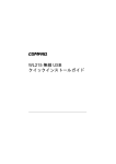
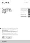
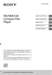
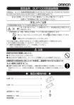
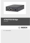
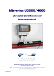
Installation of the AP-4000
1
Installazione dell'Unità AP-4000
Installation de l’unité AP-4000
NOTE:
NOTE:
NOTA:
Before installing and using this product, see the “Regulatory
Compliance” section of the AP-4000 User Guide for important
Regulatory Compliance information.
Avant l’installation et l’utilisation de ce produit, veuillez vous référer
à la partie « Regulatory Compliance » (conformité aux
réglementations) du « AP-4000 User Guide » (Manuel d’utilisation
AP-4000) pour obtenir toutes les informations concernant la
conformité aux réglementations.
Prima di installare ed utilizzare questo prodotto, fare riferimento alla
sezione relativa alla “Regulatory Compliance” (conformità alle
norme) della “AP-4000 User Guide” (Guida per l'utente del software
AP-4000), dove sono contenute importanti informazioni su tale
conformità.
Verify Kit Contents
•
•
•
•
•
AP-4000 unit with integrated 802.11b/g and 802.11a radios, and Active
Ethernet
Mounting plate for wall or ceiling mounting
Security cover
Power adapter
CD-ROM containing software and documentation
Additional Items Required
•
•
•
Windows® 95 or higher PC with CD-ROM drive
A cross-over Ethernet cable to initialize the unit
Microsoft® IE 6 with Service Pack 1 or later and patch Q323308 or
Netscape® 7.1 or higher web browser
2 Install Software and Documentation
Insert the CD into your computer CD-ROM drive and install the software and
documentation.
— User Guide in PDF format is located in:
C:\Program Files\ORiNOCO\AP4000\PDF
— The ScanTool icon is installed on your desktop and added to the Start
> ORiNOCO menu.
3 Cable the AP-4000
1.
2.
3.
4.
5.
6.
Plug the power cord into the power jack and connect the unit to an AC
power outlet (100~240V, 50~60Hz).
If using active Ethernet, connect power to the unit from a DC injector device,
such as the 1-Port Active Ethernet DC Injector hub.
Optionally, connect an RS-232 cable to the RS-232 console port.
Wait for the power LED to turn green before proceeding.
Connect the AP-4000 LAN port to a stand-alone PC using a cross-over
Ethernet cable, or to a network hub or switch.
When the RS-232 cable is not connected, you may optionally install a
security cover to prevent access to the power and LAN ports, and the reset
and reload buttons:
— Slide the hinging end of the security cover into the hole on the rear
panel of the AP-4000 to the left of the connectors.
— Use two screws to attach the right side of the security cover to the RS232 screw holes on the rear panel of the AP-4000.
1
Vérifier le contenu de la trousse
•
•
•
•
•
Autres articles requis
•
•
•
5 Initialize the AP-4000
There are two ways to connect the AP-4000 unit to your computer:
A. Connect the AP-4000 unit to a stand-alone PC using the cross-over
Ethernet cable, and determine the IP address of your computer (e.g.
169.x.x.x).
B. Connect the AP-4000 device to a DHCP server on the same subnet as
your computer.
If you choose path “A”, follow these steps:
1. Double-click on the ScanTool icon on your desktop.
ScanTool is a Windows® -based program that displays the AP-4000
devices and their IP addresses and allows for limited initial configuration of
the unit.
2. Click on the Change button.
3. Select Static under IP Address Assignment Type.
4. Enter an IP address for the AP-4000 unit within the same subnet as your
computer. The default IP address is 169.254.128.132.
5. You will need to enter a Read/Write Password before clicking OK. The
default password is public.
If you choose path “B”, double-click on the ScanTool icon on your desktop to
find the IP address of your AP-4000, and continue with the next step.
6 Basic Configuration
1.
2.
3.
4.
5.
Open your browser and enter the IP Address configured in Step 5. Press
Enter. Result: The AP-4000 Login screen appears.
Leave the user name field empty, enter your password (default is public),
and click OK. Result: The System Status screen appears.
Click the Configure button. Result: The System Configuration screen
appears. Each tab contains information for specific configuration categories.
Select the Interfaces tab.
Enter a primary Network Name (SSID). You can later configure multiple
SSID/VLAN pairs (up to 16 for each wireless interface) and define security
profiles for each pair. Refer to the “Advanced Configuration” section in the
user guide.
Insérez le CD dans le lecteur de CD-ROM de l’ordinateur et installez le logiciel
et la documentation.
— Le manuel d’utilisation en format PDF est situé dans :
C:\Programmes\ORiNOCO\AP4000\PDF
— L’icône ScanTool est installée sur le Bureau et ajoutée au menu Démarrer
> ORiNOCO.
3 Câbler l’AP-4000
1.
2.
3.
4.
5.
6.
1.
2.
3.
Install a wireless card in a laptop or other computer, including the drivers
and the management software.
Configure the card to match the network name and encryption key of one of
the wireless interfaces on the AP-4000 unit.
Verify that your Client Manager application shows association with the AP4000 device.
8 Network Configuration
Refer to “Advanced Configuration” in the AP-4000 User Guide to setup the
following features.
— DHCP server
— RADIUS server
— SSID and VLAN pairs and security profiles
— Wireless interface settings
PN 70868
© 2005 Proxim Corporation
Branchez le cordon d’alimentation dans le connecteur et reliez l’unité à une
prise d’alimentation secteur (100~240V, 50~60Hz).
Si la connexion Ethernet active est utilisée, alimentez l’unité à partir d’un
injecteur de puissance CC, tel que l’injecteur CC Wireless LAN Active
Ethernet à un port.
Reliez éventuellement un câble RS-232 au port de la console RS-232.
Attendez que le voyant devienne vert avant de poursuivre.
Branchez le port d’accès LAN AP-4000 à un PC autonome utilisant un câble
croisé Ethernet ou à un commutateur ou concentrateur de réseau.
Lorsque le câble RS-232 n’est pas branché, vous pouvez éventuellement
installer un capot de protection pour interdire l’accès à l’alimentation et aux
ports d’accès LAN, et aux boutons de réinitialisation et de recharge :
— Faites glisser la partie articulée du capot de protection dans l’orifice sur
le panneau arrière de l’AP-4000 à gauche des connecteurs.
— Utilisez deux vis pour visser le côté droit du capot de protection dans
les trous prévus pour RS-232 sur le panneau arrière de l’AP-4000.
Effectuez une enquête sur le site pour déterminer le meilleur emplacement pour
le dispositif. Après avoir choisi le lieu d’emplacement final de l’unité, fixez l’AP4000 à un mur ou à un plafond en « T » de la façon suivante :
Pour monter l’AP-4000 à un plafond :
1. Montez la plaque de montage sur la base de l’AP-4000 en alignant les
mortaises et en fixant la plaque à l'aide des deux vis.
2. Refermez les pattes sur la barre en « T ». Faire pivoter l’unité AP-4000
jusqu’à ce qu’elle se ferme sur la barre en « T ».
Pour monter l’AP-4000 contre un mur :
1. Placez la plaque de montage contre le mur. Les boutons qui s’adaptent
dans les mortaises de l’AP-4000 doivent être d’aplomb.
2. Vissez la plaque.
3. Placez l’AP contre la plaque de montage. Orientez l’AP avec l’accès long à
la verticale, et les connecteurs vers la droite.
Vous pouvez éventuellement installer l’une des quatre antennes d’extension de
portée double bande sur l’AP-4000. Reportez-vous au Manuel d’utilisation de
l’AP-4000 pour plus de détails sur l’installation.
5 Initialiser l’AP-4000
Il y a deux manières de brancher l’unité AP-4000 à un ordinateur :
A. Branchez l’unité AP-4000 à un PC autonome en utilisant le câble
croisé Ethernet, et déterminez l’adresse IP de l’ordinateur (p. ex.
169.x.x.x).
B. Branchez le dispositif AP-4000 à un serveur DHCP sur le même sousréseau que l’ordinateur.
Si vous choisissez la voie « A », effectuez ces étapes :
1. Cliquez deux fois l’icône ScanTool sur le Bureau.
ScanTool est un programme Windows® qui affiche les dispositifs AP-4000
et leurs adresses IP et permet une configuration initiale limitée de l’unité.
2. Cliquez sur le bouton Change.
3. Sélectionnez Static devant l’option IP Address Assignment Type.
4. Saisissez l’adresse IP pour l’unité AP-4000 sur le même sous-réseau que
l’ordinateur. L'adresse IP par défaut est 169.254.128.132.
5. Vous devez entrer un mot de passe de lecture/d'écriture avant de cliquer sur
OK. Le mot de passe par défaut est public.
Si vous choisissez la voie « B », cliquez deux fois l’icône ScanTool sur le
Bureau pour déterminer l’adresse IP de l’AP-4000, et passez à l’étape suivante.
6 Configuration de base
1.
2.
3.
Ouvrez votre navigateur et saisissez l’adresse IP configurée dans l’étape 5.
Appuyez sur Enter. Résultat : L’écran de connexion Login de l’AP-4000
apparaît.
N’ajoutez rien dans le champ User name, entrez votre mot de passe (par
défaut public) et cliquez OK. Résultat : L’écran System Status apparaît.
Cliquez sur le bouton Configure. Résultat : L’écran System Configuration
apparaît. Chaque onglet contient des informations sur les différentes
catégories de configuration.
Sélectionnez l’onglet Interfaces.
Entrez le nom du réseau primaire devant Network Name (SSID). Vous
pouvez par la suite configurer plusieurs paires SSID/VLAN (au total, 16 par
interface sans fil) et définir les profils de sécurité pour chaque paire. Se
reporter à « Advanced Configuration » (Configuration avancée) dans le
manuel d’utilisation.
7 Test d'association
1.
2.
3.
Installez une carte PC sans fil dans un ordinateur portable ou autre, ainsi
que les pilotes et l’application Client Manager.
Configurez le carte en tenant compte du nom du réseau et de la clé de
chiffrement de l’une des interfaces sans fil de l’unité AP-4000.
Vérifiez que Client Manager montre l’association avec le dispositif AP-4000.
8 Configuration réseau
Reportez-vous à « Advanced Configuration » (Configuration avancées) dans le
manuel d’utilisation de l’AP-4000 pour configurer les fonctions suivantes.
— Serveur DHCP
— Serveur RADIUS
— Profils de sécurité et paires SSID et VLAN
— Paramètres de l’interface sans fil
2
1
Verifica del contenuto del kit
•
•
•
•
•
Unità AP-4000 con i componenti 802.11b/g e 802.11a integrati e una
scheda Active Ethernet
Piastra per montaggio a parete o a soffitto
Pannello di protezione
Adattatore di alimentazione
CD-ROM contenente il software e la documentazione
Altri elementi necessari
•
•
•
2.
3.
4.
5.
6.
4
•
1.
2.
FRONT
3.
4.
5
5.
1
6.
2
3
4
3.
4.
5.
7 Verifica dell'associazione
1.
2.
3.
Installare una scheda per PC wireless in un laptop o un altro computer,
nonché i driver e l'applicazione Client Manager.
Configurare la scheda in base al nome della rete e alla chiave di codifica di
una delle due interfacce wireless sull'unità AP-4000.
Verificare che l'applicazione Client Manager mostri l'associazione con l'unità
AP-4000.
8 Configurazione della rete
Per impostare le seguenti funzioni consultare la sezione “Advanced
Configuration” nell'AP-4000 User Guide.
— Server DHCP
— Server RADIUS
— Coppie SSID e VLAN e profili di protezione
— Impostazioni delle interfacce wireless
Das Benutzerhandbuch im PDF-Format befindet sich in:
C:\Programme\ORiNOCO\AP4000\PDF
Das ScanTool-Symbol wird auf dem Desktop installiert und zum Menü
Start > ORiNOCO hinzugefügt.
Stecken Sie das Netzkabel in die Strombuchse ein, und schließen Sie die
Einheit an eine Wechselstromsteckdose (100~240 V, 50~60 Hz) an.
Wenn Active Ethernet verwendet wird, benötigen Sie zur Stromversorgung der
Einheit einen DC-Injector, zum Beispiel das Wireless LAN 1-Port Active Ethernet
DC Injector-Hub.
Optional können Sie ein RS-232-Kabel an den RS-232-Konsole-Port
anschließen.
Warten Sie, bis die LED-Anzeige der Stromversorgung auf grün schaltet, bevor
Sie fortfahren.
Schließen Sie den AP-4000-LAN-Port unter Verwendung eines CrossoverEthernet-Kabels an einen Standalone-PC oder an einen Netzwerk-Hub oder
Switch an.
Wenn das RS-232-Kabel nicht angeschlossen ist, können Sie auf Wunsch eine
Sicherheitsabdeckung installieren, um den Zugang zu den Strom- und LANAnschlüssen und den Reset- und Reload-Tasten zu verhindern:
— Das Scharnierende der Sicherheitsabdeckung auf der Rückseite des AP4000 in die Öffnung links neben den Anschlüssen einschieben.
— Verwenden Sie zwei Schrauben, um auf der Rückseite des AP-4000 die
rechte Seite der Sicherheitsabdeckung an den RS-232-Schraubenlöchern
festzuschrauben.
Führen Sie eine Standortprüfung durch, um den besten Aufstellort für das Gerät zu
bestimmen. Nachdem Sie einen endgültigen Aufstellort gewählt haben, montieren
Sie den AP-4000 wie folgt an eine Wand oder eine Aufhängevorrichtung an der
Decke:
Montieren des AP-4000 an eine Decke:
1. Montieren Sie die Befestigungsplatte an die Unterseite des AP-4000, indem Sie
die Schlüssellöcher ausrichten und die Platte mit zwei Schrauben
festschrauben.
2. Rasten Sie die Laschen an der Aufhängevorrichtung an der Decke ein. Drehen
Sie den AP-4000, bis er an der Aufhängevorrichtung an der Decke einrastet.
Montieren des AP-4000 an eine Wand:
1. Halten Sie die Befestigungsplatte an die Wand. Die Knöpfe, die in die
Schlüssellöcher am AP-4000 passen, sollen eine vertikale Linie bilden.
2. Schrauben Sie die Befestigungsplatte an.
3. Halten Sie den AP gegen die Befestigungsplatte. Richten Sie den AP so aus,
dass die lange Seite vertikal und die Anschlüsse rechts zu liegen kommen.
Als Option können Sie auf dem AP-4000 eine bis vier Dual-Band-ReichweitenErweiterungsantennen installieren. Installationsanweisungen finden Sie in der AP4000-Benutzeranleitung.
5 Initialisieren des AP-4000
5
6
1
2
Zum Anschließen der AP-4000-Einheit an den Computer gibt es zwei Möglichkeiten:
A. Schließen Sie die AP-4000-Einheit unter Verwendung des CrossoverEthernet-Kabels an einen Standalone-PC an, und ermitteln Sie die IPAdresse des Computers (z. B. 169.x.x.x).
B. Schließen Sie das AP-4000-Gerät an einen DHCP-Server im gleichen
Subnetz wie der Computer an.
Wenn Sie Pfad “A” wählen, befolgen Sie diese Schritte:
1. Doppelklicken Sie auf das ScanTool-Symbol auf dem Desktop.
ScanTool ist ein Windows®-basiertes Programm, das die AP-4000-Geräte und
deren IP-Adressen anzeigt und eine begrenzte Erstkonfiguration der Einheit
ermöglicht.
2. Klicken Sie auf die Schaltfläche Change (Ändern).
3. Wählen Sie unter "IP Address Assignment Type" (IP-Adresszuweisungstyp) die
Option Static (Statisch).
4. Geben Sie für die AP-4000-Einheit eine IP-Adresse im gleichen Subnetz wie der
Computer ein. Die standardadresse ist 169.254.128.132.
5. Sie müssen ein Lese-/Schreibkennwort eingeben, bevor Sie auf OK klicken. Das
Standardkennwort lautet public.
Wenn Sie Pfad “B” wählen, doppelklicken Sie auf das ScanTool-Symbol auf dem
Desktop, um die IP-Adresse des AP-4000 zu bestimmen, und fahren Sie mit dem
nächsten Schritt fort.
6 Basiskonfiguration
1.
6 Configurazione di base
2.
PC mit CD-ROM-Laufwerk und Windows® 95 oder höher
Ein Crossover-Ethernet-Kabel zum Initialisieren der Einheit
Webbrowser Microsoft® IE 6 mit Service Pack 1 oder höher und Patch
Q323308 oder Netscape® 7.1 oder höher
4 Montieren des AP-4000
5 Inizializzazione dell'AP-4000
Aprire il browser e inserire l'indirizzo IP configurato nel punto 5. Premere
Invio. Risultato: appare la schermata Login dell'unità AP-4000.
Lasciare vuoto il campo del nome utente, inserire la password (quella
predefinita è public) e fare clic su OK. Risultato: appare la schermata
System Status.
Fare clic sul pulsante Configure. Risultato: appare la schermata System
Configuration. Ciascuna scheda contiene le informazioni per le categorie di
configurazione specifiche.
Selezionare la scheda Interfaces.
Inserire un Network Name (SSID) primario. Successivamente è possibile
configurare più coppie SSID/VLAN (fino a 16 per ciascuna interfaccia
wireless) e definire le profili di protezione per ciascuna coppia. Consultare la
sezione “Advanced Configuration” nel manuale d'uso.
AP-4000-Einheit mit integrierten 802.11b/g- und 802.11a-Funkmodulen und
Active Ethernet
Befestigungsplatte für Wand- oder Deckenmontage
Sicherheitsabdeckung
Stromadapter
CD-ROM mit Software und Dokumentation
3 Verkabeln des AP-4000
Esaminare il sito per determinare la posizione migliore per il dispositivo. Dopo
aver scelto una posizione definitiva per l'unità, montare l'AP-4000 su una parete
o sul soffitto con barra a T procedendo come segue.
Montaggio dell'AP-4000 a soffitto
1. Fissare la piastra di montaggio alla base dell'AP-4000 allineando le
scanalature e serrando le due viti.
2. Fissare le linguette sulla barra a T del soffitto; uno scatto indica l'avvenuto
fissaggio. Ruotare l'unità AP-4000 in modo da fissarla alla barra a T finché
non si avverte uno scatto.
Montaggio dell'AP-4000 a parete
1. Sistemare la piastra di montaggio sulla parete. I pomelli che vanno nelle
scanalature sull'AP-4000 devono essere allineati verticalmente
2. Fissare la piastra di montaggio con le viti.
3. Posizionare l'AP contro la piastra di montaggio. Orientare l'AP con il
pannello di accesso lungo in posizione verticale e i connettori rivolti a destra.
Volendo, sull'AP-4000 è possibile installare da una a quattro antenne Dual
Band Range Extender. Per le istruzioni sull'installazione consultare l'AP-4000
User Guide.
1.
Prüfen des Kit-Inhalts
•
4 Montaggio dell'AP-4000
Sono disponibili due modi per collegare l'unità AP-4000 al computer.
A. Collegare l'unità AP-4000 a un PC autonomo usando il cavo Ethernet
di crossover e determinare l'indirizzo IP del computer (del tipo
169.x.x.x).
B. Collegare l'unità AP-4000 a un server DHCP sulla stessa subnet del
computer.
Se si sceglie il percorso “A”, eseguire la procedura seguente.
1. Fare doppio clic sull'icona ScanTool sul desktop.
ScanTool è un programma basato su Windows® che visualizza i dispositivi
AP-4000 e i loro indirizzi IP e consente una configurazione iniziale limitata
dell'unità.
2. Fare clic sul pulsante Change.
3. Selezionare Static sotto IP Address Assignment Type.
4. Inserire un indirizzo IP per l'unità AP-4000 all'interno della stessa subnet del
computer. Il indirizzo IP predefinita è 169.254.128.132.
5. Prima di fare clic su OK occorre inserire una password di lettura/scrittura. La
password predefinita è public.
Se si sceglie il percorso “B”, fare doppio clic sull'icona ScanTool sul desktop
per trovare l'indirizzo IP dell'unità AP-4000 in questione, e passare al punto
successivo.
製品をインストールしてご使用になる前に、『AP-4000 User Guide (AP4000 ユーザー ガイド )』の「Regulatory Compliance」セクションを参
照し、使用許諾に関する重要な事項を確認してください .
Legen Sie die CD in das CD-ROM-Laufwerk des Computers ein und installieren Sie
die Software und die Dokumentation.
BACK
Inserire il cavo di alimentazione nell'apposito connettore e collegare l'unita
a una presa di alimentazione in c.a. (100~240 V, 50~60 Hz).
Se si usa Active Ethernet, alimentare l'unità mediante un dispositivo di
iniezione in c.c., come l'hub Wireless LAN 1-Port Active Ethernet DC
Injector.
Volendo, è possibile collegare un cavo RS-232 alla porta della consolle RS232.
Attendere che il LED di alimentazione diventi verde prima di continuare.
Collegare la porta LAN dell'AP-4000 a un PC autonomo, usando un cavo
Ethernet di crossover, o a un hub o switch di rete.
Quando non si adopera il cavo RS-232, vi è la possibilità di installare un
pannello di protezione che impedisce l'accesso al connettore di
alimentazione, alla porta LAN e ai pulsanti Reset e Reload.
— Far scorrere l'estremità a cerniera del pannello di protezione nel foro
sul pannello posteriore dell'AP-4000, a sinistra dei connettori.
— Fissare il lato destro del pannello di protezione inserendo due viti RS232 negli appositi fori sul pannello posteriore dell'AP-4000.
Antes de instalar y usar este producto, consulte la sección
"Regulatory Compliance” (Cumplimiento de la normativa) de la “AP4000 User Guide” (Guía del usuario del AP-4000) para conocer
información importante relacionada con el cumplimiento de las
normas.
2 Software und Dokumentation installieren
3 Collegamento dell'AP-4000
1.
Bitte lesen Sie vor der Installation und Verwendung dieses Produkts
im „AP-4000 User Guide” (AP-4000 Benutzerhandbuch) den
Abschnitt „Regulatory Compliance" (Einhaltung von Gesetzen und
Richtlinien) mit wichtigen Informationen zur Einhaltung der
gesetzlichen Vorschriften.
•
•
•
documentazione
Inserire il CD nell'unità per CD-ROM del computer e installare il software e la
documentazione.
— La guida per l'utente in formato PDF si trova in:
C:\Programmi\ORiNOCO\AP4000\PDF
— L'icona ScanTool viene installata sul desktop e aggiunta al menu Avvio >
ORiNOCO.
注記 :
Weitere Anforderungen
PC con Windows® 95 o superiore e unità per CD-ROM
Un cavo Ethernet di crossover (incrociato) per inizializzare l'unità
Microsoft® IE 6 con Service Pack 1 o successivo e patch Q323308 o
browser Web Netscape® 7.1 o superiore
AP-4000 ユニットのインストール
NOTA:
•
•
•
•
3
Instalación de la Unidad AP-4000
ANMERKUNG:
•
2 Installazione del software e della
4 Monter l’AP-4000
4.
5.
7 Association Test
PC fonctionnant sous Windows® 95 ou mieux avec lecteur CD-ROM
Un câble croisé Ethernet pour initialiser l’unité
Navigateur Web Microsoft® IE 6 avec Service Pack 1 ou plus récent, et un
correctif Q323308, ou Netscape® 7.1 ou plus récent
2 Installer le logiciel et la documentation
4 Mount the AP-4000
Conduct a site survey to determine the best location for your device. Once you
have chosen a final location for your unit, mount the AP-4000 to a wall or a Tbar ceiling as follows:
To mount the AP-4000 to a ceiling:
1. Attach the mounting plate to the bottom of the AP-4000 by lining up the
keyholes and attaching it with two screws.
2. Snap the tabs onto the ceiling T-bar. Rotate the AP-4000 until it snaps on to
the T-bar.
To mount the AP-4000 to a wall:
1. Put the mounting plate up to the wall. The knobs that fit into the keyholes
on the AP-4000 should be in a vertical line.
2. Screw through the mounting plate.
3. Place the AP up against the mounting plate. Orient the AP with the long
access vertical, with the connectors facing right.
You can optionally install one to four Dual Band Range Extender Antennas on
the AP-4000. Refer to the AP-4000 User Guide for installation instructions.
Unité AP-4000 avec radios 802.11b/g et 802.11a intégrées et Active
Ethernet
Plaque de montage mural ou plafond
Capot de protection
Adaptateur d’alimentation
CD-ROM contenant le logiciel et la documentation
1
Installation des AP-4000
2.
3.
4.
5.
3
Öffnen Sie Ihren Browser und geben Sie die in Schritt 5 konfigurierte IPAdresse ein. Drücken Sie die Eingabetaste. Ergebnis: Der AP-4000-Bildschirm
Login (Anmeldung) wird eingeblendet.
Lassen Sie das Benutzernamenfeld leer, geben Sie Ihr Kennwort ein (Standard
ist public) und klicken Sie auf OK. Ergebnis: Der Bildschirm System Status
(Systemstatus) wird eingeblendet.
Klicken Sie auf die Schaltfläche Configure (Konfigurieren). Ergebnis: Der
Bildschirm System Configuration (Systemkonfiguration) wird eingeblendet.
Jede Registerkarte enthält Informationen für bestimmte
Konfigurationskategorien.
Wählen Sie die Registerkarte Interfaces (Schnittstellen) aus.
Geben Sie einen primären Network Name (SSID) (Netzwerknamen) ein. Sie
können später mehrere SSID/VLAN-Paare (bis zu 16 pro Wireless-Schnittstelle)
konfigurieren und für jedes Paar Sicherheitsmodi definieren. Siehe Abschnitt
“Advanced Configuration” in dieser Benutzeranleitung.
7 Beziehungstest
1.
2.
3.
Installieren Sie eine Wireless-PC-Karte in einen Laptop oder anderen Computer
sowie die Treiber und die Client Manager-Anwendung.
Konfigurieren Sie die Karte, sodass der Netzwerkname und der
Verschlüsselungsschlüssel mit einer Wireless-Schnittstelle in der AP-4000Einheit übereinstimmen.
Prüfen Sie, ob die Client Manager-Anwendung die Beziehung mit dem AP-4000Gerät anzeigt.
8 Netzwerkkonfiguration
Informationen zum Einrichten der folgenden Funktionen finden Sie in der AP-4000Benutzeranleitung unter “Advanced Configuration”.
— DHCP-Server
— RADIUS-Server
— SSID- und VLAN-Paare und Sicherheitsmodi
— Wireless-Schnittstelleneinstellungen
1
Verifique el contenido de la caja
•
•
•
•
•
Unidad AP-4000 con radios 802.11b/g y 802.11a integradas y un hub
Ethernet activo
Placa de montaje para instalación en techo o pared
Tapa de seguridad
Adaptador eléctrico
CD-ROM con el software y la documentación
Elementos adicionales necesarios
•
•
•
PC con Windows® 95 o mejor y lectora de CD-ROM
Un cable Ethernet con cruce de enlaces para inicializar la unidad
Microsoft® IE 6 con Service Pack 1 o mejor, e instalador Q323308 o
explorador de Internet Netscape® 7.1 o mejor
2 Instalar el software y la documentación
Inserte el CD en la lectora de CD-ROM e instale el software y la
documentación.
— La guía del usuario en formato PDF está en:
C:\Archivos de programas\ORiNOCO\AP4000\PDF
— El icono ScanTool (Buscar herramientas) se instala en su escritorio en el
menú Inicio > ORiNOCO.
3 Conectar el AP-4000
1.
2.
3.
4.
5.
6.
Conecte el cable de alimentación en el enchufe y conecte la unidad a un
tomacorriente de CA (100~240 V, 50~60 Hz).
Si utiliza Ethernet activo, conecte la electricidad a la unidad desde un
dispositivo inyector de CC tal como el hub Ethernet activo del inyector de
CC de Ethernet activo de un puerto de LAN inalámbrica.
Si lo desea, conecte un cable RS-232 al puerto de la consola RS-232.
Antes de proceder, espere que el LED verde de la energía se encienda.
Conecte el puerto LAN del AP-4000 a una PC independiente utilizando un
cable Ethernet con cruce de enlaces, o a un hub o conmutador de red.
Cuando el cable RS-232 no está conectado, usted puede instalar, si lo
desea, una tapa de seguridad para evitar el acceso a la electricidad y a los
puertos LAN, y a los botones de reinicialización y recarga:
— Deslice el extremo con bisagras de la tapa de seguridad en el orificio
del panel posterior del AP-4000 que se encuentra a la izquierda de los
conectores.
— Utilice dos tornillos para asegurar la parte derecha de la tapa de
seguridad a los orificios para tornillos del RS-232 del panel posterior
del AP-4000.
4 Instalar el AP-4000
Realice una inspección del lugar para determinar la mejor ubicación para el
dispositivo. Cuando haya elegido la ubicación definitiva para la unidad, instale
el AP-4000 en una pared o en techo de barras en T, como se indica a
continuación:
Para instalar el AP-4000 en el techo:
1. Adose la placa de montaje a la base del AP-4000 alineando los orificios de
referencia y fijándolo con dos tornillos.
2. Encaje a presión las aletas en la barra en T del techo. Gire el AP-4000 hasta
que encaje a presión en la barra en T.
Para instalar el AP-4000 en la pared:
1. Coloque la placa de montaje en la pared. Las perillas que encajan en los
orificios de referencia del AP-4000 deben estar en línea vertical.
2. Coloque un tornillo a través de la placa de montaje.
3. Coloque el AP arriba y contra la placa de montaje. Oriente el AP con el
acceso largo vertical, con los conectores mirando hacia la derecha.
Si lo desea, puede instalar hasta cuatro antenas de rango extenso y banda
doble en el AP-4000. Remítase a la Guía del usuario del AP-4000 para conocer
las instrucciones de instalación.
5 Inicializar el AP-4000
Existen dos formas de conectar la unidad AP-4000 a su computadora:
A. Conecte la unidad AP-4000 a una PC independiente utilizando el
cable Ethernet con cruce de enlaces, y determine la dirección IP de su
computadora (por ejemplo, 169.x.x.x).
B. Conecte el dispositivo AP-4000 a un servidor DHCP en la misma
subred de su computadora.
Si elige la vía “A”, siga los siguientes pasos:
1. Haga doble clic en el icono ScanTool de su escritorio.
ScanTool es un programa basado en Windows® que muestra los
dispositivos AP-4000 y sus direcciones IP y permite la configuración inicial
limitada de la unidad.
2. Haga clic en el botón Change.
3. Seleccione Static en Tipo de asignación de la dirección IP.
4. Ingrese una dirección IP para la unidad AP-4000 dentro de la misma subred
de su computadora. La dirección IP predeterminada es 169.254.128.132.
5. Deberá ingresar una contraseña de lectura/escritura antes de hacer clic en
OK. La contraseña predeterminada es public.
Si elige la vía “B”, haga doble clic en el icono ScanTool de su escritorio para
encontrar la dirección IP de su AP-4000, y continúe con el paso siguiente.
6 Configuración básica
1. Abra el explorador e ingrese la dirección IP que se configuró en el Paso 5.
Presione Enter. Resultado: Aparece la pantalla Login del AP-4000.
2. Deje el campo del nombre de usuario vacío, ingrese su contraseña (la
predeterminada es public), y haga clic en OK. Resultado: Aparece la pantalla
System Status.
3. Haga clic en el botón Configure. Resultado: Aparece la pantalla System
Configuration. Cada ficha contiene información sobre las categorías
específicas de configuración.
4. Seleccione la ficha Interfaces.
5. Ingrese un Network Name primario (SSID). Luego podrá configurar otros
pares de SSID/VLAN (hasta 16 por cada interfaz inalámbrica) y definir los
perfiles de seguridad para cada par. Remítase a la sección “Configuración
avanzada” de la Guía del usuario.
7 Prueba de asociación
1.
2.
3.
Instale una tarjeta PC inalámbrica en una laptop u otra computadora, junto
con los controladores y la aplicación Client Manager.
Configure la tarjeta para que coincida con el nombre de la red y la clave de
encriptación de una de las interfaces inalámbricas de la unidad AP-4000.
Verifique que la aplicación Client Manager muestre la asociación con el
dispositivo AP-4000.
8 Configuración de la red
Remítase a “Configuración avanzadas” de la Guía del usuario del AP-4000
para configurar las siguientes características.
— Servidor DHCP
— Servidor RADIUS
— Pares SSID y VLAN y perfiles de seguridad
— Configuraciones de la interfaz inalámbrica
1
キットの内容の確認
Q
Q
Q
Q
Q
AP-4000 ユニット(統合 802.11b/g、802.11a ラジオ、アクティブ Ethernet
を内蔵)
壁および天井に設置するための取り付けプレート
セキュリティカバー
電源アダプタ
ソフトウェアおよびマニュアルを収録した CD-ROM
上記に挙げたものの他に以下の品目が必要です。
Q
Q
Q
CD-ROM ドライブを搭載した Windows® 95 またはそれ以降の PC
ユニットを初期化するためのクロスオーバー Ethernet ケーブル
Microsoft® IE 6(Service Pack 1 以降とパッチ Q323308 を適用したバー
ジョン)または Netscape® 7.1 以降のウェブブラウザ
2 ソフトウェアとマニュアルのインストール
コンピュータの CD-ROM ドライブに製品 CD-ROM を挿入し、ソフトウェアとマニュ
アルをインストールします。
Q
PDF 形式のユーザー ガイドは次の場所に保存されます。
C:\Program Files\ORINOCO\AP4000\PDF
Q
デスクトップと [ スタート ] - > [ORiNOCO] メニューに ScanTool のアイコン
が追加されます。
3 AP-4000 の接続
1.
2.
3.
4.
5.
6.
電源コードを電源ジャックに差し込み、ユニットを AC 電源コンセント(100
~ 240V、50 ~ 60Hz)に接続します。
アクティブ Ethernet を使用する場合は、Wireless LAN 1-Port Active
Ethernet DC Injector ハブなどの DC 電源供給デバイスから電源をユニット
に接続します。
必要な場合は、RS-232 ケーブルを RS-232 コンソールポートに接続します。
電源 LED が緑色に点灯したことを確認してください。
クロスオーバー Ethernet ケーブルを使って AP-4000 の LAN ポートをネット
ワークに接続していない PC に接続します。または、AP-4000 の LAN ポートを
ネットワークハブまたはスイッチに接続します。
RS-232 ケーブルを接続しない場合は、電源ジャックや LAN ポート、リセット
とリロードボタンを保護するセキュリティカバーを、以下の手順に従って取り
付けることができます。
セキュリティカバーのちょうつがいが付いた端を AP-4000 の背面パネルの穴
に合わせ、コネクタの左側に向かってスライドさせます。
セキュリティカバーの右側と AP-4000 の背面パネルにある RS-232 のネジ穴
に、ネジ 2 個を取り付けます。
4 AP-4000 の設置
デバイスを設置する場所を決めます。デバイスを設置する場所が決まったら、次の
手順に従って AP-4000 を壁または吊り天井に設置します。
AP-4000 を天井に設置するには
1. 穴を合わせて取り付けプレートを AP-4000 の底部に 2 つのネジで固定し、取
り付けます。
2. 吊り天井にタブを取り付けます。AP-4000 ユニットをカチッという音がするま
でするまで回転させます。
AP-4000 を壁に設置するには
1. 壁に取り付けプレートを配置します。AP-4000 の穴に入れたノブが垂直になる
はずです。
2. ネジで取り付けプレートを固定します。
3. AP-4000 を取り付けプレートに合うように配置します。AP-4000 の長い辺が垂
直、コネクタが右側になるようにユニットの方向を合わせます。
AP-4000 には、オプションで 4 つまでのデュアルバンドレンジ拡張アンテナを設
置できます。設置手順については、
AP-4000 のユーザーガイドを参照してください。
5 AP-4000 の初期化
AP-4000 ユニットをコンピュータに接続するには、次の 2 つの方法があります。
キA. クロスオーバー Ethernet ケーブルを使って AP-4000 をネットワークに
接続していない PC に接続し、コンピュータの IP アドレスを指定します(例
: 169.x.x.x)
。
キ B. AP-4000 デバイスをコンピュータと同じサブネット内にある DHCP サー
バーに接続します。
上記の手順 5A を選択した場合は、次の手順に従います。
1. デスクトップにある ScanTool のアイコンをダブルクリックします。
ScanTool は、AP-4000 デバイスとその IP アドレスを表示し、ユニットの簡単
な初期設定を行う Windows® 用プログラムです。
2. [Change] ボタンをクリックします。
3. [IP Address Assignment Type] で [Static] を選択します。
4. コンピュータと同じサブネット内にある AP-4000 ユニットの IP アドレスを
入力します。
169.254.128.132.
5. [Read/Write Password] を入力してから [OK] をクリックしてください。デ
フォルトのパスワードは、
「public」です。
上記の手順 5B を選択した場合は、デスクトップにある ScanTool のアイコンをダ
ブルクリックして、AP-4000 の IP アドレスを見つけ、次の手順に進みます。
6 基本構成
1.
2.
3.
4.
5.
ブラウザを開き、手順 5 で設定した IP アドレスを入力し、Enter キーを押
します。これで、AP-4000 の [Login] 画面が表示されます。
ユーザー名は空白のままにしておき、パスワード(デフォルトは public)だ
けを入力して、[OK] をクリックします。これで、[System Status] 画面が表
示されます。
[Configure] ボタンをクリックします。これで、[System Configuration] 画
面が表示されます。各タブには、それぞれのカテゴリに関する情報が表示され
ます。
[Interfaces] タブを選択します。
プライマリ [Network Name](SSID)を入力します。後で、複数の SSID/VLAN
ペア(各ワイヤレスインターフェースにつき最高で 16 まで)を設定し、各ペ
アでセキュリティモードを定義できます。詳しくは、ユーザーガイドの「詳細
設定」を参照してください。
7 接続の確認
1.
2.
3.
ワイヤレス PC カードをノートブックコンピュータまたはその他のコンピュー
タに取り付けます。ドライバと Client Manager アプリケーションもインス
トールします。
ネットワーク名と AP-4000 ユニットのワイヤレスインターフェースのいずれ
かの暗号化キーが一致するように各カードを設定します。
Client Manager アプリケーションに AP-4000 デバイスとの接続が表示されて
いることを確認します。
8 ネットワークの構成
次の機能を設定するには、AP-4000 のユーザーガイドにある「詳細設定」を参照し
てください。
—
—
—
—
DHCP サーバー
RADIUS サーバー
SSID および VLAN ペアおよびセキュリティモード
ワイヤレスインターフェースの設定