1
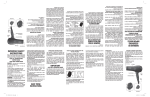
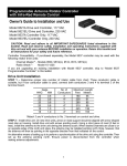
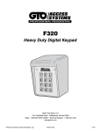
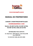
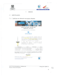
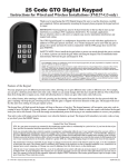
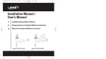
GTO Digital Keypad
Instructions
For Wireless or Wired Applications
The GTO Digital Keypad is a multipurpose keypad that can work with other applications, in addition
to GTO gate openers and locks.
As a wired keypad it can operate garage door openers as well as gate openers that use accessories
with normally open contacts and require 24 volts or less.
As a wireless keypad it can be used with any gate or garage door opener that receives a 318 MHz FM
signal. It must be used in conjunction with the GTO garage door receiver kit on any other garage
door.
NOTE: Due to unknown interferences, some installations may not be able to be used as a wireless
application.
You may program up to fifteen different personal entry codes, allowing you to give different entry codes to different users.
For example, you can give a delivery person their own entry code, which you can change after they have made the delivery.
This will prevent them from being able to regain access, while still allowing those to whom you gave other entry codes full
access.
Thank you for purchasing the GTO Digital Keypad. Please read the directions, program the keypad and test its range before
permanently mounting the keypad.
Teclado numérico digital GTO
Instrucciones en español, página 6
Para instalaciones con y sin cables
Además de funcionar con abridores y seguros de puertas corredizas GTO, el teclado numérico
GTO se puede usar con otras aplicaciones.
Cuando se instala con cables, el teclado puede controlar abridores de puertas de garaje y otros
tipos de abridores de puertas corredizas que utilicen accesorios con contactos normalmente
abiertos que requieran 24 voltios o menos.
Cuando se instala sin cables, el teclado se puede utilizar con cualquier tipo de abridor de puertas
corredizas o de puertas de garaje que reciba una señal de FM de 318 MHz, y también se puede
usar en conjunto con el juego de receptor para puerta de garaje GTO o con cualquier otro tipo de
puerta de garaje.
Se pueden programar hasta quince códigos personales de entrada, lo cual permite asignar diferentes códigos de entrada a
diferentes personas. Por ejemplo, se le puede dar un código de entrada específico a alguien que venga a hacerle una entrega y
luego cambiarlo una vez hecha la entrega. Esto impide que la persona vuelva a entrar usando el mismo código, en tanto que
sigue permitiendo completo acceso a aquellas personas a quienes se hayan dado otros códigos de entrada.
Le agradecemos que haya adquirido uno de nuestros teclados numéricos digitales GTO. Por favor lea las instrucciones,
programe el teclado y compruebe su alcance antes de instalarlo permanentemente.
GTO, Inc. • 3121 Hartsfield Road • Tallahassee, Florida 32303
Phone (850) 575-0176 • Fax (850) 575-8912 • www.gtoinc.com
RB927
Rev. 04/19/01
©2000 GTO, Inc.
Features of the Keypad
The keypad requires an entry code to activate the gate opener. This entry code can
either be the factory code or your own personal code. After the last key in your entry
code is pressed, the keypad will send a signal to activate your gate opener. Press any
key while the gate is opening and the gate will stop; press any key while the gate is
stopped and the gate will reverse direction. The keypad will not affect the auto-close
setting of your gate opener system.
The keypad face will light up at the press of any key. The key does not have to be one
of your entry code numbers. The keypad memory will recognize your entry code in a
string of up to 18 digits; if it finds the correct sequence it will activate the gate opener.
As a security feature, the keypad will shut down for 40 seconds if it does not find the
correct code sequence within an 18 digit string. This will discourage an unauthorized
person from trying to use random numbers to access your property.
The RED light above the number keys will (1) light up and blink dimly when any key
is pressed; (2) flash brightly and rapidly when transmitting signal; and (3) blink slowly
and brightly when the batteries are low.
Your entry codes will remain stored in memory even when the batteries go dead. The
keypad will remember your entry codes as long as you don’t simultaneously press
keys 3, 6, and 9 while replacing the batteries.
Red light
1
2
3
4
5
6
7
8
9
0
Programming Button
(use pen or small screwdriver
to depress button)
FCC Regulation
This device complies with FCC rules Part 15.
Operation is subject to the following two conditions:
1 – This device may not cause harmful interference. 2 – This device must accept an interference that may cause undesired operation.
Transmitter distance may vary due to circumstances beyond our control.
Installing Batteries
2
3
4
5
6
7
8
9
1
Step 1: Remove the two screws from the bottom of the keypad and separate the keypad from its
housing. This will give you access to the battery holder and the terminal.
0
Step 2: Install 3 AA batteries (not included). These are required to provide
power to the LED light and key lights.
Batteries
Entry Transmitter
If you have not changed your Entry Transmitter’s DIP switch code
(i.e., it is still set to the factory setting), test the operation of the
keypad and its range using the keypad factory code “1234”. This
should activate your opener.
If you have changed your Entry Transmitter’s DIP switch code from the factory
settings, you will need to program the keypad to match the Entry Transmitter’s DIP
switch code. See page 2 for programming instructions.
If you plan to use the keypad as a wireless application, follow the instructions below. If you are going to use the keypad as a
wired application, please turn to page 3 for instructions.
SAFETY NOTE:
Never install the keypad where a person can reach through the gate to activate it, or where a person can touch the gate
while activating the keypad. The recommended minimum distance between the gate and keypad is 10 ft.
1
Wireless Installation of Keypad
For most wireless applications, the distance from the keypad to the receiver(s) should not exceed 50 ft. Always test the
keypad range before permanently mounting it. If interference causes undesirable range, the keypad must be installed as a
“Wired Keypad” (see page 3).
Programming Keypad to match the Entry Transmitter internal DIP switch code.
NOTE: This is not necessary if you have not changed the Entry Transmitter’s DIP switch code from the factory setting.
To program your keypad to match your entry transmitter's internal code press:
‘P’,
‘1’ ‘2’ ‘3’ ‘4’
Programming
Button
‘P’,
‘0’,
Programming
Button
Factory
Master Code
‘P’,
Transmitter's Internal ,
Dip Switch Code
Programming
Button
Designates
Transmitter Code
‘P’
Programming
Button
Match Dip Switch
Code in Transmitter
Open transmitter to find
internal dip switches.
Example:
, Inc
.
, Inc
.
Keypad number: 4 7 1 4 7 4 1 4 1
Equivalent to dip switch setting: (0) (–) (+) (0) (–) (0) (+) (0) (+)
1 2 3 4 5 6 7 8 9
Numbers (1, 4, 7) on keypad
are used to match the (+, 0, –)
dip switch settings in the
Entry Transmitter.
+
0
AMP
Dip switch found in Entry Transmitter
+=
1
2
3
0=
4
5
6
–=
7
8
9
0
Programming Button
After you have programmed the keypad to match the Entry Transmitter’s internal DIP switch code, test the operation of your
keypad by using the factory code “1234”.
2
Wireless Installation of Keypad, continued
Step 1: Mount the keypad cover using
the large screws provided. Slide the
keypad face into the cover and secure
with the small screws at the bottom of
the keypad face.
2
3
4
5
6
7
8
9
1
0
Step 2: Program your master code and
additional entry codes. See page 5.
Mount the Keypad Cover
Secure Keypad with screws
Wired Installation of the Keypad
Step 1:
Always turn the control box OFF before you connect an accessory to the operator
control board!
Use 16 gauge, stranded, direct burial low voltage wire (see GTO Accessory
Catalog) to connect the keypad to the opener control box (NOTE: use the same gauge
wire for the jumper wire). Run wire through PVC pipe from the ground to keypad
and from the ground to the opener control box to protect the wire from lawn mowers
or grazing animals.
Determine how the wire will enter the keypad (i.e. from the back through a hole
drilled in the mounting post or running the wire on the surface of the post).
Pull the wire through the plastic grommet in the back of the keypad cover. Then
mount the keypad cover to the post using the large screws provided.
Illustration A
connect to WHT terminal on
the operator control board
connect to GRN terminal on
the operator control board
JUMP
WHT (Common)
GRN (Normally Open)
To wire keypad directly to operator – use 16 gauge,
stranded, low voltage, direct burial wire.
Step 2: Strip 3/16” of insulation from the wires and attach them to the
terminal block on the keypad control board as shown in Illustration A. The
wire from the terminal marked GRN on the keypad control board connects to
the ACCESSORY terminal marked GRN on the operator control board. The
wire from the terminal marked WHT on the keypad control board connects
to the ACCESSORY terminal marked WHT on the operator control board.
Connect a short jumper wire from the JUMP terminal to the GRN terminal
on the keypad control board. See illustrations on page 4 for instructions on
wiring the keypad to the control board.
connect jumper wire to
GRN terminal on this
board (do not use if
keypad is wireless).
2
3
4
5
6
7
8
9
1
0
Step 3: Place keypad into keypad
cover and secure using the small
screws provided.
Jumper Wire
To WHT Terminal on
Operator Control Board
To GRN Terminal on
Operator Control Board
3
Wired Installation of the Keypad, continued
Illustration B
POWER IN
STATUS
PWR. SW.
–
BATT
BLU
WHT
ORG
GRN
OPN EDG
CLS EDG
ORG
BLU
GRN
RED
BLK
OPN EDG
CLS EDG
ORG
BLU
GRN
BLK
RED
M
ALAR
Y
SSOR
ACCE
B
R G
RCVR
ATOR
ND OPER
SECO
FIRST
R IN
WHT
BLU
ORG
GRN
ALARM ACCESSORY
Connect wire from the
GRN terminal on the
keypad to the
ACCESSORY terminal
marked GRN on the
control board.
ON
OPN EDG
CLS EDG
GRN
BLU
ORG
BLK
OPN EDG
CLS EDG
GRN
BLU
RED
SECOND OPERATOR
LEARN
R
G
B
RCVR
Connect wire from the
WHT terminal on the
keypad to the
ACCESSORY terminal
marked WHT on the
control board.
.
LEARN
POWE
SEQ1
SEQ2
INERTIA
OBSTR
SENS.
SOLAR
18VAC – +
~ ~
FIRST OPERATOR
Generation 2000 Control
Board for:
AUTO
CLOSE
+
ORG
18VAC SOLAR
~ ~ –
+
BLK
Step 4: Unscrew and remove control
box cover. Feed the wires through the
strain relief on the lower left of the
control box (Illustration B) and attach
them to the ACCESSORY terminal
block of the 2000 Generation board
shown in Illustration C, or the 1996
Generation, shown in Illustration D.
RED
NOTE: If you have an early model GTO gate operator and your control board does not resemble any of these, please call GTO
Technical Support at 1-800-543-GATE [4283] for wiring instructions.
ATOR
OPER
Mighty Mule®, GTO/PRO
1000, 2000, and SL-1000
series operators.
Low Voltage
Wire from Keypad
Illustration C
Illustration D
Generation 1996 Control Boards
With Terminal Blocks
®
AUTOMATIC GATE OPENERS
®
AUTOMATIC GATE OPENER
S1
S2
SOLAR
WHT
BLU
ORG
GRN
S5
BLK
TRANSFORMER
S4
RED
BLK
RED
SOLAR
Receiver
Terminal Block
BLK
RED
BLK
RED
TRANSFORMER
S3
Accessory
Terminal Block
Power
Terminal Block
Connect wire from
the WHT terminal
on the keypad here.
Connect wire from
the WHT terminal
on the keypad here.
Connect wire from
the GRN terminal
on the keypad here.
Connect wire from
the GRN terminal
on the keypad here.
From Keypad
Wire
rom Keypad
Wire F
Step 5: Tighten the strain relief screw, replace and fasten the cover and turn the control box ON. Test the keypad by entering
1-2-3-4.
Step 6: Program your master code and additional entry codes (see page 5).
4
Programming your personal entry codes.
The factory master code is 1234. Pressing these four keys in sequence will send a signal to your gate opener. For enhanced
security, we strongly recommend changing the factory code to your own personal code. To reset the keypad to the factory
master code you must disconnect a battery and simultaneously press the 3, 6, and 9 keys while you replace it. Remember
that this will erase any codes previously entered.
NOTE: The more digits in your code, the more secure it will be.
Before you begin programming, the keypad must be in the inactive mode (keys must be unlit).
To change the Factory Master Code to your Personal Master Code press:
‘P’,
‘1’,
‘2’,
‘3’,
‘4’,
‘P’,
‘1’,
‘P’,
Programming
Button
Programming
Button
Factory
Master Code
your Personal Master Code (3 to 6 digits),
Programming
Button
'P’
Programming
Button
Your Personal Master Code
(example: '1', '5', '7', '9')
Designates
First (Master)
Entry Code
To enter a second entry code press:
‘P’,
your Personal Master Code,
Programming
Button
‘P’,
‘2’,
Programming
Button
Your Personal Master Code
(example: '1', '5', '7', '9')
‘P’,
second code (1 to 6 digits),
Programming
Button
Designates Second
Entry Code
‘P’
Programming
Button
Second Entry Code
(example: '2', '5', '7', '9')
To enter a third entry code press:
‘P’,
your Personal Master Code,
Programming
Button
‘P’,
‘3’,
Programming
Button
Your Personal Master Code
(example: '1', '5', '7', '9')
‘P’,
third code (1 to 6 digits),
Programming
Button
Designates Third
Entry Code
‘P’
Programming
Button
Third Entry Code
(example: '3', '5', '7', '9')
… and so on up to 15 different codes.
If you have any questions or concerns, please contact the GTO Service Department at 1-800-543-GATE
[4283] or (850) 575-0176.
Limited One Year Warranty
GTO, Inc. gate opener accessories are warranted by the manufacturer against defects in workmanship for a period of one (1) year from the date of purchase, provided
recommended installation procedures have been followed.
In the case of product failure due to defective material or manufacturer workmanship within the one (1) year warranty period, the accessory will be repaired or replaced
(at the manufacturer’s option) at no charge to the customer, if returned freight prepaid to GTO, Inc., 3121 Hartsfield Rd., Tallahassee, Florida, USA 32303.
IMPORTANT: Call (850) 575-0176 or Fax (850) 575-8950 for a Return Goods Authorization (RGA) number before returning goods to factory. Products received at the
factory without an RGA will not be accepted. Replacement or repaired parts are covered by this warranty for the remainder of the one (1) year warranty period or six (6)
months, whichever is greater. GTO, Inc. will pay the shipping costs (equal to United Parcel Service ground rate) for return to the owner of items repaired.
The manufacturer will not be responsible for any charges or damages incurred in the removal of the defective parts for repair, or for the reinstallation of those parts after
repair. This warranty shall be considered void if damage to the product(s) was due to improper installation or use, connection to an improper power source, or if damage
was caused by lightning, wind, fire, flood, insects, or other natural agent.
After the one (1) year warranty period, GTO Inc. or one of its authorized service centers will make any necessary repairs for a nominal fee. Call GTO at (850) 575-0176
for more information. This warranty gives you specific legal rights, and you may also have other rights which may vary from state to state. This warranty is in lieu of all
other warranties, expressed or implied. NOTE: Verification of the warranty period requires copies of receipts or other proof of purchase. Please retain those
records.
5
Funciones del teclado numérico
El teclado necesita un código de entrada para activar el abridor de la puerta. Este
código puede ser el que se fija en la fábrica o uno personal que defina el usuario (vea
las instrucciones para la programación de códigos). Después de oprimir el último
número del código de entrada, el teclado envía una señal para activar el abridor de la
puerta. Para detener la puerta mientras se está abriendo, oprima un botón cualquiera; la
puerta empieza a moverse en la dirección opuesta si se oprime otro botón mientras está
inmóvil. El teclado no afecta la configuración de cerrado automático del sistema
abridor de la puerta corrediza.
El teclado se ilumina cada vez que se oprime un botón. No es necesario que el botón
sea uno de los botones del código de entrada. La memoria del teclado reconoce el
código de entrada en una secuencia de hasta 18 dígitos; si encuentra la secuencia
correcta, activa el abridor. Para su seguridad, el teclado se apaga por 40 segundos si no
encuentra el código correcto dentro de la secuencia de 18 dígitos. Esto contribuye a
disuadir a personas no autorizadas para que no intenten combinaciones aleatorias de
números para entrar a su propiedad.
Luz roja
1
2
3
4
5
6
7
8
9
0
Botón de programación
(utilice un desatornillador pequeño
o un bolígrafo para oprimirlo)
La luz ROJA que está encima de los botones numéricos (1) se ilumina y parpadea
menos intensamente cuando se oprime un botón cualquiera; (2) parpadea con
intensidad y rapidez cuando transmite la señal; y (3) parpadea con intensidad y lentitud
cuando las baterías se están agotando. Los códigos de entrada permanecerán en la memoria aunque las baterías se hayan
agotado completamente. El teclado recuerda los códigos de entrada siempre y cuando no se hayan oprimido simultáneamente
los números "3", "6" y "9" al reemplazar las baterías.
Reglamento de la FCC
Este dispositivo cumple con la Parte 15 del Reglamento de la FCC.
Su funcionamiento está sujeto a las siguientes dos condiciones:
1 – Este dispositivo no debe causar interferencias perjudiciales
2 – Este dispositivo debe aceptar interferencias que puedan dar como resultado un funcionamiento no deseado.
El alcance del transmisor puede variar por circunstancias fuera de nuestro control.
Instalación de las baterías
2
3
4
5
6
7
8
9
1
Paso 1: Quítele los dos tornillos de la parte inferior al teclado y sepárelo de su alojamiento. De esta
forma tendrá acceso al portador de baterías y al terminal.
Paso 2: Instale 3 baterías AA (no incluidas). Son necesarias para que se
encienda el indicador luminoso y las luces de los botones para
instalaciones con o sin cables.
0
Baterías
Si no ha cambiado el código del interruptor DIP interno de su
transmisor de entrada (es decir que todavía está configurado con el
código de fábrica) compruebe el funcionamiento del teclado y su
alcance. Use el código de fábrica "1234". Esto debería activar el
abridor.
Transmisor GTO
Si se ha cambiado el código del interruptor DIP interno de su transmisor de entrada,
es necesario que programe el teclado numérico para que coincida con el código del
interruptor. En la página 7 hay instrucciones de programación.
Si planea utilizar el teclado numérico para aplicaciones sin cables, siga las instrucciones que se dan a continuación. Pase a la
página 8 si lo va a utilizar en aplicaciones con cables.
NOTA DE SEGURIDAD:
Nunca instale el teclado numérico en lugares en que una persona pueda activarlo a través de la puerta corrediza, o en que una persona pueda
tocar la puerta mientras lo activa. Se recomíenda dejar una distancia minima de 3 metros entre la puerta y la caja de teclado.
6
Instalación sin cables del teclado numérico
Para la mayoría de las aplicaciones sin cables, la distancia entre el teclado y el receptor (o los receptores) no debe exceder 17
metros. Compruebe siempre el alcance del teclado antes de instalarlo permanentemente.
Programación del teclado numérico para que coincida con el código del interruptor DIP interno
del transmisor de entrada
NOTA: Esto no es necesario si el teclado está conectado al tablero de control o si no se ha cambiado el código de fábrica con
que viene configurado.
Para aumentar la seguridad de su sistema, cambie el código de fábrica con que viene configurado el interruptor
DIP interno del transmisor de entrada. (Vea la sección titulada "Configuración del código personal del transmisor"
en el manual de instalación del abridor de la puerta corrediza.)
Para programar el teclado de modo que coincida con el código interno del transmisor de entrada oprima:
‘P’,
‘1’ ‘2’ ‘3’ ‘4’
‘P’,
‘0’,
‘P’,
Código para el interruptor ‘P’
DIP interno del transmisor
Botón de
Botón de
programación programación
Botón de
programación
Código maestro
de fábrica
Designa el
código del transmisor
Botón de
programación
Hágalo coincidir con el código para
el interruptor DIP interno del transmisor
Abra el transmisor para encontrar
los interruptores DIP
internos.
Ejemplo:
, Inc.
, Inc
.
Números del teclado : 4 7 1 4 7 4 1 4 1
Equivalente a la posición del interruptor DIP: (0) (–) (+) (0) (–) (0) (+) (0) (+)
1 2 3 4 5 6 7 8 9
Los números (1, 4 y 7) del
teclado numérico se usan como
equivalentes de las posiciones
(+, 0 y -) de la configuración del
interruptor DIP en el transmisor
de entrada.
AMP
Interruptor DIP en el transmisor de entrada
+
0
+=
1
2
3
0=
4
5
6
–=
7
8
9
0
Botón de programación
Una vez haya programado el teclado numérico para que coincida con el código del interruptor DIP del transmisor
de entrada compruebe el funcionamiento del teclado. Use el código de fábrica "1234".
7
Instalación sin cables del teclado numérico, continuación
Paso 1: Monte la cubierta del teclado
numérico con los tornillos largos que se
incluyen. Deslice el teclado en la
cubierta y sujételo con los tornillos
pequeños que se encuentran en su parte
inferior.
2
3
4
5
6
7
8
9
1
0
Paso 2: Programe su código maestro
personal de entrada y los códigos de
entrada adicionales. Vea la página 10.
Monte la cubierta del
teclado numérico
Sujete el teclado numérico
con los tornillos
Instalación con cables del teclado numérico
Paso 1:
¡Síempre asegurece que el interruptor de la caja de control esté apagado en la posicion
OFF antes de conectar cualquíer accesorio al circuito del tablero!
Use un cable trenzado de enterrado directo calibre 16 de bajo voltaje (vea el Catálogo de
accesorios de GTO) para conectar el teclado numérico a la caja de control del abridor
(NOTA: use este mismo cable para la conexión de puente). Haga pasar el cable por el tubo
de PVC desde el suelo al teclado y desde el suelo a la caja de control del abridor para
proteger el cable contra cortadoras de césped o animales que pastan.
Determine la forma en que el cable va a entrar en el teclado (por detrás a través de un
agujero taladrado en el poste de montaje o colocando el cable por la superficie del poste).
Saque el cable por la arandela plástica que hay en la parte posterior de la cubierta del
teclado. Luego, monte la cubierta del teclado numérico en el poste con los tornillos
grandes que se incluyen.
Paso 2: Remueva 3/16” pulgadas del aislante plastico de los cables para
conectarlos en el tablero del teclado como muestra la Ilustración A. El
Ilustración A
terminal marcado GRN en el teclado, va conéctado a la seccion de
ACCESSORY del tablero marcado GRN en la caja de control. El terminal
marcado WHT en el teclado va conéctado a la seccion de ACCESSORY del
tablero marcado WHT en la caja de control. Conécte un cable entre el
conéctor marcado GRN y JUMP haciendo un puente, en el tablero del
teclado. Vea las illustraciones en la página 9 que tiene informacíon de como
hacer las conécciones del teclado a la caja de control.
connect to WHT terminal on
the operator control board
connect to GRN terminal on
the operator control board
JUMP
GRN (Normally Open)
WHT (Common)
To wire keypad directly to operator – use 16 gauge,
stranded, low voltage, direct burial wire.
connect jumper wire to
GRN terminal on this
board (do not use if
keypad is wireless).
2
3
4
5
6
7
8
9
1
Paso 3: Coloque el teclado
numérico dentro de su cubierta y
sujételo con los tornillos pequeños
que se incluyen.
Hilo de puente
Al terminal WHT en el panel
de control del operador
Al terminal GRN en el panel
de control del operador
8
0
Instalación con cables del teclado numérico, continuación
POWER IN
FIRST OPERATOR
Tablero de control 2000
Generación para:
Ilustración B
Mighty Mule®, GTO/PRO
1000, 2000 y SL-1000
Abridores de Puertas
SECOND OPERATOR
ON
WHT
BLU
GRN
ORG
SEQ1
SEQ2
OPN EDG
CLS EDG
GRN
BLU
ORG
BLK
RED
OPN EDG
CLS EDG
GRN
BLU
ORG
18VAC SOLAR
~ ~ –
+
BLK
Paso 4: Destape la caja de control.
Por la abertura localizada en la parte
izquierda de la caja de control, afloje
los tornillos e introdusca los cables a
travez del orificío, (Ilustración B),
conécte los cables en la seccion de
ACCESSORY del tablero 2000
Generación como lo indica la
ilustración C o la para la 1996
Generación como lo indica la
ilustración D.
RED
NOTA: Si usted tiene uno de los primeros modelos de abridor de puertas GTO, y el cicuito no es sémejante al ilustrado, por
favor llame al departamento de Soporte Tecnico GTO al 1-800-543-GATE o (850) 575-0176 para obtener instructiones para la
instalacíon.
LEARN
R
ALARM ACCESSORY
G
B
RCVR
Conécte el terminal
marcado GRN (verde)
en el teclado a la
seccion de
ACCESSORY del
tablero de control
marcado GRN.
Conécte el terminal
marcado WHT
(blanco) en el teclado
a la seccion de
ACCESSORY del
tablero de control
marcado WHT.
Cable de bajo voltaje
que viene del teclado numérico
Ilustración C
Reductor
de tensión
PVC
Tableros de Control 1996 Generación
con Bloques Terminales.
®
®
AUTOMATIC GATE OPENER
AUTOMATIC GATE OPENERS
S1
S2
Bloque de
terminales de
alimentación
SOLAR
WHT
BLU
ORG
GRN
TRANSFORMER
S5
BLK
RED
BLK
RED
SOLAR
S4
BLK
RED
BLK
RED
TRANSFORMER
S3
Bloque de
terminales
receptor
Conecte aquí el cable
del terminal WHT del
teclado numérico
Bloque de
terminales para
accesorios
Conecte aquí el cable
del terminal GRN del
teclado numérico
Conecte aquí el cable
del terminal WHT del
teclado numérico
Conecte aquí el cable
del terminal GRN del
teclado numérico
Cable del teclado numérico
Cable del teclado numéri c o
Paso 5: Apriete los tornillos de la abertura por donde introdujo las cables, despues instale de regreso la tapa de la caja. Mueva
el interruptor de la caja de control a la posicion ON y pruebe el teclado presionando el codigo 1-2-3-4.
Paso 6: Programe su código maestro personal de entrada y los códigos de entrada adicionales. Vea la página 10.
9
Programación del código maestro principal y de los
códigos de entrada adicionales
Paso 6: El código maestro de fábrica es “1234”. Cuando se oprimen estos números seguidos, se envía una señal al abridor
de la puerta. Para reforzar la seguridad, le recomendamos enfáticamente que cambie este código a uno exclusivamente
suyo. Si se necesita que el teclado numérico recupere el código maestro de fábrica hay que desconectar una de las baterías y
oprimir simultáneamente las teclas “3”, “6” y “9” mientras la reemplaza. Recuerde que este procedimiento borrará todos los
códigos que se haya introducido.
NOTA: Mientras más dígitos tenga el código maestro, más seguro será.
Antes de comenzar la programación, el teclado numérico debe estar en modalidad inactiva
(los botones deben estar apagados).
Para cambiar el código maestro de fábrica a su código personal oprima:
‘P’,
‘1’,
‘2’,
‘3’,
‘4’,
‘P’,
‘1’,
Botón de
programación
Botón de
programación
Código maestro
de fábrica
‘P’, Su
your
Personal
Master
Code(de
(3 to
código
maestro
personal
3 a66digits),
dígitos) 'P’
Botón de
programación
Botón de
programación
Su código maestro personal
(ejemplo: “1”, “5”, “7”, “9”)
Designa el primer
código de entrada
(maestro)
Para programar un segundo código de entrada oprima:
‘P’,
your
Su código
Personal
maestro
Master
personal
Code,
Botón de
programación
‘P’,
‘2’,
Botón de
programación
Su código maestro personal
(ejemplo: “1”, “5”, “7”, “9”)
‘P’, Segundo
secondcódigo
code(de
(1 to
1 a66 digits),
dígitos)
Botón de
programación
Designa el segundo
código de entrada
‘P’
Botón de
programación
Segundo código de entrada
(ejemplo: “2”, “5”, “7”, “9”)
Para programar un tercer código de entrada oprima:
‘P’,
your
Personal
Master
Code,
Su código
maestro
personal
Programming
Button
‘P’,
‘3’,
Programming
Button
Su código maestro personal
(ejemplo: “1”, “5”, “7”, “9”)
‘P’, Tercer
third código
code (1
(deto1 6a 6digits),
dígitos) ‘P’
Botón de
programación
Designa el tercer
código de entrada
Botón de
programación
Tercer código de entrada
(ejemplo: “3”, “5”, “7”, “9”)
De esta manera se pueden programar hasta 15 códigos diferentes.
Si usted tiene alguna pregunta, por favor llame al Departamento de Servico de GTO al 1-800-543-GATE (4283)
o (850) 575-0176.
Garantía Limitada por Un Año para Accesorios para Controlador de Puertas
Los accesorios para la operación de puertas GTO están garantizados por el fabricante contra defectos en materiales y mano de obra por un periodo de un (1) año a partir de la fecha
de su compra, siempre que los procedimientos de instalación hayan sido seguidos.
En caso de que este producto fallase debido a materiales o mano de obra defectuosos dentro del periodo de garantía de un (1) año, los accesorios serán reparados o remplazados (a
opción del fabricante) sin costo al cliente, siempre que este producto sea regresado con flete pagado a GTO, Inc. 3121 Hartsfield Road, Tallahassee, Florida, USA 32303.
IMPORTANTE: llame al número (850) 575-0176 o envíe un fax al número (850) 575-8950 para pedir un número de Autorización para Regresar Productos (o número
RGA) antes de regresar cualquier accesorio o parte a la fabrica. Productos que sean enviados a la fabrica sin número RGA no serán aceptados. Cambio o reparacion de partes
estan cubiertos por esta garantía por el restante del año de la garantía original del producto o un periodo de seis (6) meses, cualquíera que sea mayor. GTO, Inc. pagara el costo del
fléte por tierra que sea equivalente a United Parcel Service, para regresa los productos reparados a sus clientes.
El fabricante no será responsable por cargos o daños que ocurriesen al remover las partes defectuosas para ser reparadas, o por la instalación de esas partes después de haber sido
reparadas. Esta garantía deberá considerarse nula si daños a este producto fueron causados debido a la instalación o uso inapropiado, conexión a una toma de corriente eléctrica no
propia para este producto, o si los daños fueron causados por relámpagos, viento, fuego, inundaciones, insectos u otras causas naturales.
Después de la expiración de esta garantía, GTO, Inc. o uno de sus centros de servicio autorizados realizará las reparaciones que fueran necesarias por un precio nominal. Llame a
GTO al número (904) 575-0176 para obtener más información. Esta garantía le da derechos legales específicos, usted además pudiera tener algunos otros derechos los cuales varían
de estado a estado. Esta garantía reemplaza a cualquier otra garantía explícita o implícita. Nota: Para verificar que la garantía del producto está vigente requerimos nos
proporcione copias de los recibos de compra o de algún otro documento prueba de compra. Por favor guarde estos documentos.
10